Article

Monte Carlo Simulation of Electron Interactions in an MeV-STEM for Thick Frozen Biological Sample Imaging

1
Laboratory for BioMolecular Structure, Brookhaven National Laboratory, Upton, NY 11973, USA
2
National Synchrotron Light Source II, Brookhaven National Laboratory, Upton, NY 11973, USA
*
Authors to whom correspondence should be addressed.
Appl. Sci. 2024, 14(5), 1888; https://doi.org/10.3390/app14051888
Submission received: 19 January 2024 / Revised: 20 February 2024 / Accepted: 23 February 2024 / Published: 25 February 2024
(This article belongs to the Special Issue Advances in Molecular Imaging and Its Biomedical Application)

Abstract

:
A variety of volume electron microscopy techniques have been developed to visualize thick biological samples. However, the resolution is limited by the sliced section thickness (>30–60 nm). To preserve biological samples in a hydrated state, cryo-focused ion beam scanning electron microscopy has been developed, providing nm resolutions. However, this method is time-consuming, requiring 15–20 h to image a 10 μm thick sample with an 8 nm slice thickness. There is a pressing need for a method that allows the rapid and efficient study of thick biological samples while maintaining nanoscale resolution. The remarkable ability of mega-electron-volt (MeV) electrons to penetrate thick biological samples, even exceeding 10 μm in thickness, while maintaining nanoscale resolution, positions MeV-STEM as a suitable microscopy tool for such applications. Our research delves into understanding the interactions between MeV electrons and frozen biological specimens through Monte Carlo simulations. Single elastic scattering, plural elastic scattering, single inelastic scattering, and plural inelastic scattering events have been simulated. The electron trajectories, the beam profile, and the intensity change of electrons in each category have been investigated. Additionally, the effects of the detector collection angle and the focal position of the electron beam were investigated. As electrons penetrated deeper into the specimen, single and plural elastic scattered electrons diminished, and plural inelastic scattered electrons became dominant, and the beam profile became wider. Even after 10 μm of the specimen, 42% of the MeV electrons were collected within 10 mrad. This confirms that MeV-STEM can be employed to study thick biological samples.

1. Introduction

In biology and medicine, many essential processes unfold at the nanoscale. Visualizing cellular structures, organelles, and biomolecules in three dimensions allows researchers to understand the complexities of biological systems, including how cells function, communicate, and respond to stimuli. This is vital for advancing our knowledge of health and disease. It is also critical for advancements in energy storage, catalysis, and environmental science.
To visualize large/thick biological samples (e.g., cells and tissues), various volume electron microscopy (EM) techniques have been developed [1,2]. In Array Tomography, sections prepared by microtome, cryo-microtome, or ultramicrotome are imaged using scanning electron microscopes (SEMs) or TEMs with a resolution larger than 60 nm (i.e., the section thickness). In serial block face SEM (SBF-SEM) or Focused Ion Beam Scanning Electron Microscopy (FIB-SEM), the top surface is imaged with repeated material removal from the top surface, and the resolution is limited by the slice thickness ( ~ 30 100   nm ). To ensure that biological samples are as close as possible to their native state, cryo-FIB-SEM has been developed [3,4,5,6,7] with a resolution as high as a few nanometers. However, depending on the imaging parameters, it takes 15–20 h to image a 10 mm thick sample with a slice thickness of 8 nm and an area of 3 × 2 mm2 (8 nm pixel size) [7]. In addition, there are charging artifacts, curtaining artifacts, and linear artifacts [3,5].
As shown [8,9,10,11], STEM has been employed to study biological samples up to 1000 nm thick, which is much thicker than that can be imaged by cryo-Electron Microscopy (cryo-EM) or cryo-Electron Tomography (cryo-ET) [12,13,14,15]. In STEM, the electron beam is focused on the specimen plane, and there is no image-magnifying lens behind it. The image is formed by mapping detector counts point-by-point to scan positions. The bright-field (BF), annular dark-field (ADF), and high-angle annular DF (HAADF) images are formed by collecting electrons within small (e.g., < 10   mrad ), medium (e.g., 10 50   mrad ), and high (e.g., > 50   mrad ) angles, respectively [16,17,18]. For cryo-samples, objects with higher concentrations of heavy atoms will be preferentially detected by ADF imaging, forming the so-called “Z-contrast” (Z is the atomic number). The mass density variations in different parts of the sample are detected by BF imaging.
As the allowable sample thickness depends on the electron energy and image formation mechanism, a mega-electron-volt Scanning Transmission Electron microscope (MeV-STEM) has been proposed [19]. The high penetration of inelastic scattering signals of MeV electrons could make the MeV-STEM an appropriate microscope for imaging biological samples as thick as 10 μm or more with nanoscale resolution. The best resolution is inversely related to the sample thickness and changes from 6 nm to 24 nm when the sample thickness increases from 1 μm to 10 μm. As discussed, the resolution is mainly limited by beam broadening and low-dose limit on resolution. The broadening of the probe due to electron scattering can be estimated based on a wave optical multislice algorithm [20,21]. The plural elastic scattering of electrons at 200 keV in vacuum and amorphous ice has been estimated by Wolf et al. [10]. When multiple scattering is included, the broadening of the probe is expected to be worse and needs further investigation.
The Monte Carlo (MC) method is a statistical random sampling technique for solving complex multi-dimensional integral equations that are difficult to solve analytically. The general method was developed by Metropolis and Ulam in 1949 [22]. It is commonly used to estimate the probability of different outcomes in a process [23,24,25]. In radiation therapy to cure cancers, MC simulation-based methods have been employed to study the degradation of biomolecules by direct damage from inelastic scattering processes (most primary particles have initial energies in the MeV range) [26]. The track structure and properties of energy deposition and dose distributions have been estimated. For example, an MC simulation was performed to study the transport and energy loss of low-energy electrons (<10 keV) in liquid water [27].
Here, MC simulation is employed to study the interaction between MeV electrons and amorphous ice. The effect of plural scattering on the electron beam broadending is investigated. Also, different imaging modes have been examined, and the optimal imaging mode, which results in the smallest beam size at the existing surface of specimens, has been identified. This result further demonstrates that MeV-STEM is a novel imaging technique to visualize thick samples rapidly and efficiently while maintaining nanoscale resolution; it will significantly increase the rate of scientific discoveries.

2. Methods

2.1. Model Electron Cross-Section Formulae

When an imaging electron interacts with the specimen, it will be scattered elastically without losing energy or inelastically with energy loss. The chance of an electron undergoing event i (e.g., elastic scattering, inelastic scattering) within a sample thickness dt is given by
P = σ i ρ d t = K i d t ,            
where σ i is the cross-section for event i, and ρ is the sample density, K i is the scattering coefficient. The density of amorphous ice is 0.92 g/cm3, as used by Langmore and Smith [28] and Jacobsen et al. [29].
The angular distribution of scattering from a target atom can be described by the differential scattering cross-section. For elastic scattering, the differential cross-section follows the Rutherford formula for the screened Coulomb potential of the nuclear charge. In the Wentzel approximation, the differential cross-section for elastic scattering in first-order Born approximation becomes [10,17]:
d σ e l d Ω = 2 Z R 2 1 + E E 0 a H 1 + θ θ 0 2 2 , θ 0 = λ 2 π R , R = a H Z 1 3
where σel is the elastic scattering cross-section, Ω is the solid angle, Z is the atomic number, E is the electron energy, E0 is the rest energy of the electron, aH is the Bohr radius (0.0529 nm), θ is the scattering angle, θ 0 is the characteristic scattering angle below which 50% of the electrons are scattered into, λ is the electron wavelength. The characteristic scattering angle for oxygen is 15 mrad for 200 keV electrons. Integrating Equation (2) yields the total cross-section [10,28,30]:
σ e l 1.4 × 10 6 Z 3 2 β 2 1 0.26 Z 137 β   , β 2 = 1 E 0 E + E 0 2
The angular dependence and the cross-section of inelastic scattering can be approximated with a Bethe-model [10,18]:
d σ i n e l d Ω Z λ 4 1 + E E 0 2 4 π 2 a H 2 1 1 + θ 2 + θ 0 2 θ 0 2 2 θ 2 + θ E 2 2   , θ E = Δ E E E + E 0 E + 2 E 0
where σinel is the inelastic scattering cross-section, θ E is the characteristic angle that is responsible for the decay of the inelastic scattering, ∆ E is the mean energy loss from a single inelastic scattering event (e.g., 39.3 eV for amorphous ice [30]). An inelastic scattering is concentrated within much smaller angles than elastic scattering. The characteristic angle θ E is typically of the order of 0.1 mrad for 200 keV electrons. The cross-sections of Oxygen in amorphous ice (i.e., Oxygen-only H2O: the density of amorphous ice and atomic number of Oxygen were considered) are calculated using Equations (2) and (4), listed in Table 1 and graphed in Figure 1. The total cross-section for inelastic scattering is approximated by [28,30]
σ i n e l 1.5 × 10 6 Z 1 2 β 2 ln 2 θ c   , θ c = Δ E β 2 E + E 0
The total cross-section for scattering from amorphous ice is [31]
σ i c e = σ O _ a t o m + 2 σ H _ a t o m
where σ O _ a t o m and σ H _ a t o m are the scattering cross-sections of Oxygen and Hydrogen atoms in amorphous ice. As pointed out by Jacobsen et al. [29], the inelastic scattering of hydrogen was not accurate. Thus, the approximation proposed by Jacobsen et al. was followed. They used the empirical inelastic scattering cross-section of 8.8 pm2 at 80 keV for hydrogen to scale that at other voltages. The total inelastic cross-section of H2O is about 110% of the total inelastic cross-section for Oxygen-only ice.
After interacting with the sample, the electron would fall into the following five categories [29,30]:
  • Inoscat designates electrons undergoing no scattering;
  • I1el designates electrons being elastically scattered once, remaining within the detector collection angles;
  • Iel,plural designates electrons undergoing multiple elastic scatterings without any inelastic scatterings and remaining within the detector collection angles;
  • Iinel designates electrons undergoing at least one inelastic scattering and remaining within the detector collection angles;
  • Iout designates electrons being scattered outside the detector collection angles.
The sum of these five types of electrons is equal to the incident electron beam intensity I0:
Inoscat + I1el + Iel,plural + Iinel + Iout = I0

2.2. MC Simulation

The beam broadening in thick biological samples is governed by two effects: the geometrical beam divergence and the broadening due to plural scattering in the specimen. As discussed by Yang et al. [19], the beam divergence angle was designed to be as small as 1 mrad. The corresponding beam profile was generated based on the recently demonstrated state-of-the-art 2 pm geometrical emittance, 3 × 10 5 energy spread, and optimized chromatic (1.8 cm) and spherical (16 cm) aberrations of the STEM column [19]. An initial distribution with a total number of 10,000 electrons and the minimum root-mean-square (RMS) beam size of 1 nm and semi-convergence angle of 1 mrad at the focal position has been applied as the input file to MC simulations.
In MC simulations, an electron was chosen from the electron profile randomly, then an event (elastically scattering, inelastic scattering, or no-scattering) was chosen based on the probability of each event in thickness dt as defined by Equations (3) and (5). However, the calculated ratio between σ i n e l and σ e l ( σ i n e l / σ e l )   is about 1.4, much lower than the theoretical ratio (~26/Z) [17]. As pointed out by Dr. Henderson [32], the ratio is about 3 for 80–500 KeV electrons. Recently, Drs. Peet, Henderson, and Russo [33] showed that σ i n e l / σ e l are 4.1 and 5.3 for carbon at 300 KeV and 3 MeV, respectively. Thus, the total inelastic scattering cross-section is scaled to be three times that of the total elastic scattering cross-section, σ i n e l = 3 σ e l without considering the effect of high voltage on the ratio. The sample thickness dt was chosen to be 0.5 nm. Then, the scattering angle for elastic and inelastic scattering events was chosen based on the differential scattering cross-section for each angle interval based on Equations (2) and (4). For elastic scattering, the cross-section for each angle interval is the sum of the oxygen cross-section and two times the hydrogen cross-section. For inelastic scattering, the cross-section is 110% of the oxygen cross-section. The angle interval was set to 0.001 mrad for θ smaller than 0.6 mrad, 0.01 mrad for θ smaller than 6.3 mrad, 0.1 mrad for θ smaller than 67 mrad, 1 mrad for θ smaller than 600 mrad, and 10 mrad for other θ angles. The position of the electron was updated based on the scattering angle and the distance dt along the scattering direction. Also, the event type was recorded. The procedure was repeated for 15 mm/dt = 30,000 times. As the scattering is circularly symmetric perpendicular to the incoming electrons, only a cross-section parallel to the incoming electrons was studied in the MC simulation.
The beam size at depth t was calculated as the diameter of a disc containing 68% of the electrons reaching depth t. Each electron at depth t was classified into the five groups discussed at the end of the previous section based on the events it experienced before reaching depth t.

3. Results

3.1. Electron Beam Propagation in Vacuum

The trajectories of 10,000 electrons in vacuum are shown in Figure 2A. All the electrons landed within 42 nm of the center at a depth of 10 μm. The majority were within 10 nm of the center at a sample depth of 10 μm and 3 nm of the center at a sample depth of 1 μm (Figure 2B,C). The beam slowly broadened to 1.4 nm at a sample depth of 1 μm, and the broadening speed was slower than the geometric broadening. After that, the beam broadened at the same speed as the geometric broadening and reached 9.1 nm at a depth of 10 μm, narrower than the geometric broadening of 11 nm, as shown in Figure 2D.

3.2. Electron Intensity in Amorphous Ice at 300 keV

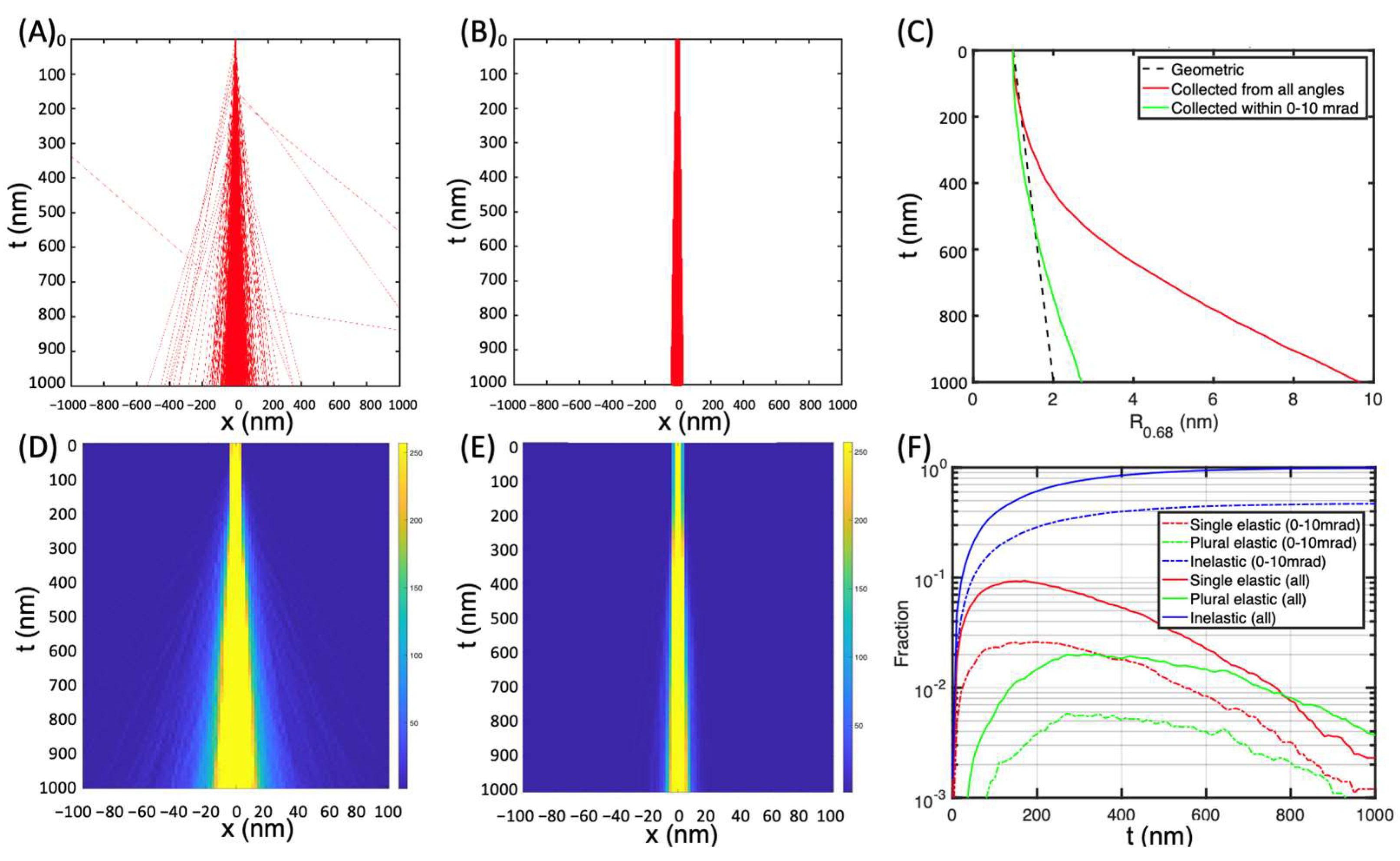
Compared with vacuum, electrons were scattered in all directions in amorphous ice. One electron was even scattered back (Figure 3A,D). As there is a limited range of collection angles of a camera, only 0–10 mrad collection angles were considered for imaging, the same as Yang et al. [19]. As expected, fewer electrons (4722) were collected within 0–10 mrad (Figure 3B,E). Correspondingly, the beam width at a depth of 1 μm was 9.7 nm, much larger than 1.4 nm in vacuum. However, if only the electrons collected within 0–10 mrad were considered, the beam radius was only 2.7 nm, which is close to that of the beam size at an incident energy of 200 keV with a semi-convergence angle of 2.9 mrad [10].
The fractions of single and plural elastically scattered electrons were 0.23% and 0.37%, respectively (Figure 3F), in good agreement with the predictions by Yang et al. [19]. The rest of the electrons were inelastically scattered. When only electrons collected within 0–10 mrad were considered, the fractions of single and plural elastically scattered electrons were 0.12% and 0.08% at a depth of 1 μm, respectively. About 47% of all incoming imaging electrons were inelastically scattered and collected on the camera within 0–10 mrad. This confirms that STEM could be used to image thicker frozen biological samples compared with conventional TEMs, which rely on elastically scattered electrons [10,11,19].

3.3. Electron Intensity in Amorphous Ice at 3 MeV

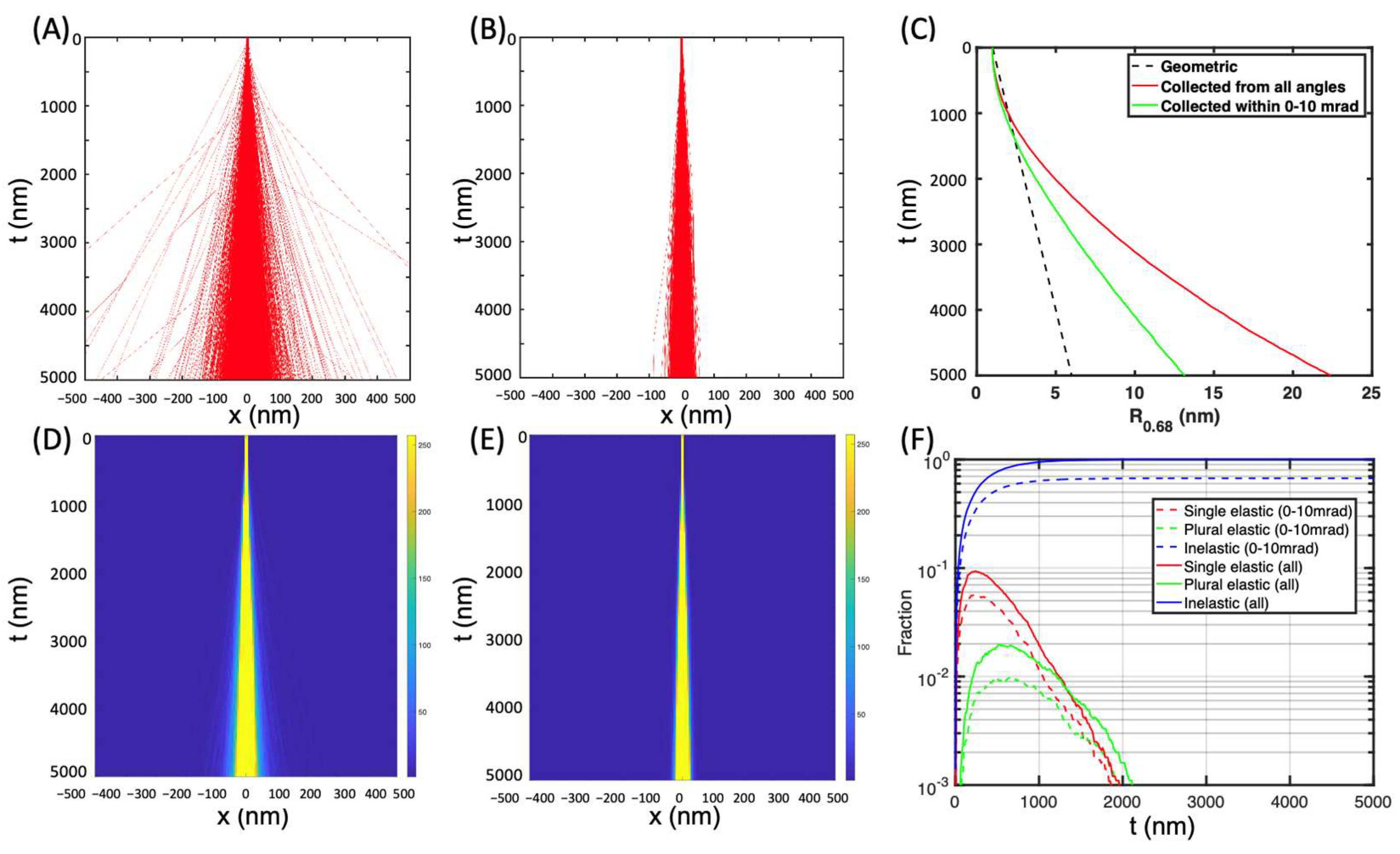
Compared with 300 keV electrons in amorphous ice, electrons traveled to a much deeper sample depth. At the sample depth of 5 μm, the trajectories of most electrons were retained within 50 nm of the center (Figure 4A,D). The beam radius was 22.2 nm. The electrons collected within 0–10 mrad were retained within 25 nm of the center (Figure 4B,E), and the radius was 12.7 nm (Figure 4C). The fractions of single and plural elastically scattered electrons were below 0.1% at the sample depth of 2 μm, while the fraction of electrons collected within 0–10 mrad was still at 67.1% (Figure 4F).
When the sample depth was doubled from 5 μm to 10 μm, electrons were scattered wider (Figure 5A,B,D,E). The trajectories of most electrons were retained within 100 nm of the center, and the beam radius was 70.9 nm. The electrons collected within 0–10 mrad were retained within 50 nm of the center (Figure 5B,E), and the radius was 27.9 nm (Figure 5C), about doubled compared with that at a depth of 5 μm. The fraction of electrons collected within 0–10 mrad was still at 41.9% (Figure 5F), decreased only by 30% compared with that at the depth of 5 μm.

3.4. Effect of Collection Angle on Electron Intensity in Amorphous Ice at 3 MeV

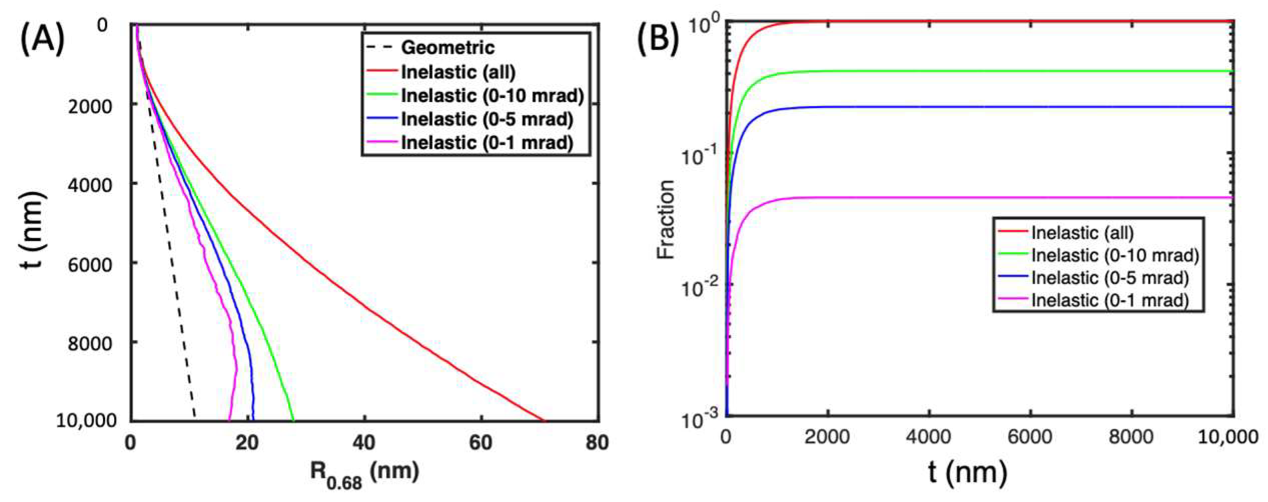
As shown in Figure 2, Figure 3 and Figure 4, the electrons collected within 0–10 mrad were retained closer to the center of the electron trajectories. Therefore, smaller collection angles were investigated. As the collection angle decreased from 0–10 mrad to 0–5 mrad and 0–1 mrad, the beam width decreased from 27.9 nm to 21.0 nm and 16.8 nm (Figure 6A). Meanwhile, the intensity of collected electrons decreased from 41.9% to 22.4% and 4.6%, respectively (Figure 6B). To reduce the beam size while maintaining a certain signal, 0–5 mrad might be better than 0–15 mrad and 0–1 mrad.

3.5. Effect of Imaging Modes on Electron Intensity in Amorphous Ice at 3 MeV

As proposed by Wolf et al. [10] and Yang et al. [19], when focusing the beam in the middle of the specimen, the geometric broadening was only 50% of that when electrons were focused on the top surface of the specimen. Here, the electrons were focused at a depth of 5 μm (i.e., defocused at 5000 nm). The beam radius at the top surface was enlarged from 1 nm to 6 nm but stays almost constant up to a depth of 2.5 μm, then follows the trend of electrons focused on the top surface of the specimen (Figure 7). As for the intensity of electrons collected within 0–10 mrad, it was the same as that when electrons were focused on the top surface of the specimen (4187 vs. 4095 electrons collected within 0–10 mrad at a depth of 10 μm).

4. Discussion

One important factor in the simulation of electron scattering in specimens is the total and differential scattering cross-section. The ratio between σ i n e l and σ e l varied in the literature. It was predicted to be ~26/Z [17] or ~20/Z [10,28], which is about 3.25 or 2.5 for oxygen in amorphous ice. Based on the theoretical calculation and the data from ICRU Report 90 published in 2016, Drs. Peet, Henderson, and Russo [33] estimated the ratio was 4.1 and 5.3 for carbon at 300 KeV and 3 MeV, respectively. The higher the ratio, the more electrons experienced inelastic scattering and the narrower the electron trajectories and the beam radius. As a starting point, the ratio of 3 was chosen in this simulation.
As proposed by Wolf et al. [10] and Yang et al. [19], when focusing the electrons in the middle of the specimen, the geometric broadening was only 50% of that when electrons were focused on the top surface of the specimen. However, in the simulation, focusing on the middle of the specimen does not help to reduce the beam radius. This may be due to the fact that as soon as electrons enter the specimen, scattering starts, and electrons cannot be focused as in a vacuum. Thus, the beam radius in this simulation was 27.9 nm, about four times larger than that proposed by Yang et al. [19] (a factor of two due to that focusing at the middle of the specimen does not reduce beam size, and another factor of two due to that multiple scattering effect becomes more significant for a 10-μm-thick specimen).
However, focusing on the middle of the specimen may benefit the STEM images, as the STEM images are formed by scanning the specimen from one spot to another spot. When electrons are focused on the top surface of the specimen, the beam profile is cone-shaped (i.e., beam radius increases as the depth increases). The formed STEM image does not cover the entire 3D slab (with void space between scanning spots in the top portion of the specimen). When electrons are focused on the middle or even the bottom of the specimen, the beam profile is cylinder-shaped, and the formed STEM image includes information from the entire 3D slab. Thus, it provides more complete and accurate information of the specimen.

Author Contributions

L.W. designed and coded the MC simulation program in Matlab and carried out the MC simulations. X.Y. generated the electron profile and carried out the MC simulations. All authors collectively contributed to the writing of the manuscript. All authors have read and agreed to the published version of the manuscript.

Funding

This research was partially funded by the DOE Office of Biological and Environmental Research grant number KP1607011, and the BNL LDRD grant number 22-029.

Data Availability Statement

The data presented in this study are available on request from the corresponding author.

Acknowledgments

We would like to thank Sharon Wolf for her valuable insights and discussions on using STEM for imaging biological samples and Lothar Houben, Andrew M. Thron, and Ming Du for their enlightening discussions on electron scattering in specimens.

Conflicts of Interest

The authors declare no competing financial and non-financial interests in relation to the work described in the paper.

References

  1. Cooper, C.; Thompson, R.C.A.; Clode, P.L. Investigating parasites in three dimensions: Trends in volume microscopy. Trends Parasitol. 2023, 39, 668–681. [Google Scholar] [CrossRef]
  2. Collinson, L.M.; Bosch, C.; Bullen, A.; Burden, J.J.; Carzaniga, R.; Cheng, C.; Darrow, M.C.; Fletcher, G.; Johnson, E.; Narayan, K.; et al. Volume EM: A quiet revolution takes shape. Nat. Methods 2023, 20, 777–782. [Google Scholar] [CrossRef]
  3. Capua-Shenkar, J.; Varsano, N.; Itzhak, N.R.; Kaplan-Ashiri, I.; Rechav, K.; Jin, X.; Niimi, M.; Fan, J.; Kruth, H.S.; Addadi, L. Examining atherosclerotic lesions in three dimensions at the nanometer scale with cryo-FIB-SEM. Proc. Natl. Acad. Sci. USA 2022, 119, e2205475119. [Google Scholar] [CrossRef]
  4. Schertel, A.; Snaidero, N.; Han, H.M.; Ruhwedel, T.; Laue, M.; Grabenbauer, M.; Möbius, W. Cryo FIB-SEM: Volume imaging of cellular ultrastructure in native frozen specimens. J. Struct. Biol. 2013, 184, 355–360. [Google Scholar] [CrossRef]
  5. Spehner, D.; Steyer, A.M.; Bertinetti, L.; Orlov, I.; Benoit, L.; Pernet-Gallay, K.; Schertel, A.; Schultz, P. Cryo-FIB-SEM as a promising tool for localizing proteins in 3D. J. Struct. Biol. 2020, 211, 107528. [Google Scholar] [CrossRef]
  6. Vidavsky, N.; Akiva, A.; Kaplan-Ashiri, I.; Rechav, K.; Addadi, L.; Weiner, S.; Schertel, A. Cryo-FIB-SEM serial milling and block face imaging: Large volume structural analysis of biological tissues preserved close to their native state. J. Struct. Biol. 2016, 196, 487–495. [Google Scholar] [CrossRef]
  7. Raguin, E.; Weinkamer, R.; Schmitt, C.; Curcuraci, L.; Fratzl, P. Logistics of Bone Mineralization in the Chick Embryo Studied by 3D Cryo FIB-SEM Imaging. Adv. Sci. 2023, 10, e2301231. [Google Scholar] [CrossRef] [PubMed]
  8. Wolf, S.G.; Elbaum, M. CryoSTEM tomography in biology. Methods Cell Biol. 2019, 152, 197–215. [Google Scholar] [CrossRef] [PubMed]
  9. Hohmann-Marriott, M.F.; Sousa, A.A.; Azari, A.A.; Glushakova, S.; Zhang, G.; Zimmerberg, J.; Leapman, R.D. Nanoscale 3D cellular imaging by axial scanning transmission electron tomography. Nat. Methods 2009, 6, 729–731. [Google Scholar] [CrossRef] [PubMed]
  10. Wolf, S.G.; Shimoni, E.; Elbaum, M.; Houben, L. Cellular Imaging: Electron Tomography and Related Techniques; Hanssen, E., Ed.; Springer International Publishing: Cham, Switzerland, 2018; pp. 33–60. [Google Scholar]
  11. Wolf, S.G.; Houben, L.; Elbaum, M. Cryo-scanning transmission electron tomography of vitrified cells. Nat. Methods 2014, 11, 423–428. [Google Scholar] [CrossRef] [PubMed]
  12. Weiner, E.; Pinskey, J.M.; Nicastro, D.; Otegui, M.S. Electron microscopy for imaging organelles in plants and algae. Plant Physiol. 2022, 188, 713–725. [Google Scholar] [CrossRef]
  13. Böhning, J.; Bharat, T.A.M. Towards high-throughput in situ structural biology using electron cryotomography. Prog. Biophys. Mol. Biol. 2021, 160, 97–103. [Google Scholar] [CrossRef] [PubMed]
  14. Oikonomou, C.M.; Jensen, G.J. Cellular Electron Cryotomography: Toward Structural Biology In Situ. Annu. Rev. Biochem. 2017, 86, 873–896. [Google Scholar] [CrossRef] [PubMed]
  15. Otegui, M.S.; Pennington, J.G. Electron tomography in plant cell biology. Microscopy 2019, 68, 69–79. [Google Scholar] [CrossRef] [PubMed]
  16. Hawkes, P.W. Advances in Imaging and Electron Physics; Elsevier: Pheladelphia, PA, USA, 2009; Volume 159. [Google Scholar]
  17. Reimer, L.; Kohl, H. Transmission Electron Microscopy: Physics of Image Formation, 5th ed.; Springer: New York, NY, USA, 2008. [Google Scholar]
  18. Tanaka, N. Electron Nano-Imaging Basics of Imaging and Diffraction for TEM and STEM, 1st ed.; Springer: Tokyo, Japan, 2017. [Google Scholar]
  19. Yang, X.; Wang, L.; Maxson, J.; Bartnik, A.; Kaemingk, M.; Wan, W.; Cultrera, L.; Wu, L.; Smaluk, V.; Shaftan, T.; et al. Towards construction of a novel nm resolution MeV-STEM for imaging of thick biological samples. arXiv 2023. [Google Scholar] [CrossRef]
  20. Wu, L.; Zhu, Y.; Vogt, T.; Su, H.; Davenport, J.W.; Tafto, J. Valence-electron distribution inMgB2by accurate diffraction measurements and first-principles calculations. Phys. Rev. B Condens. Matter Mater. Phys. 2004, 69, 064501. [Google Scholar] [CrossRef]
  21. Li, J.; Yin, W.G.; Wu, L.; Zhu, P.; Konstantinova, T.; Tao, J.; Yang, J.; Cheong, S.W.; Carbone, F.; Misewich, J.A.; et al. Dichotomy in ultrafast atomic dynamics as direct evidence of polaron formation in manganites. npj Quantum Mater. 2016, 1, 16026. [Google Scholar] [CrossRef]
  22. Metropolis, N.; Ulam, S. The Monte Carlo method. J. Am. Stat. Assoc. 1949, 44, 335–341. [Google Scholar] [CrossRef]
  23. Newman, M.E.J.; Barkema, G.T. Monte Carlo Methods in Statistical Physic; Clarendon Press: Oxford, UK, 1999. [Google Scholar]
  24. Rubinstein, R.Y. Simulation and the Monte Carlo Method; Wiley: Hoboken, NJ, USA, 1981. [Google Scholar]
  25. Fielding, A.L. Monte-Carlo techniques for radiotherapy applications I: Introduction and overview of the different Monte-Carlo codes. J. Radiother. Pract. 2023, 22, e80. [Google Scholar] [CrossRef]
  26. Hahn, M.B. Accessing radiation damage to biomolecules on the nanoscale by particle-scattering simulations. J. Phys. Commun. 2023, 7, 042001. [Google Scholar] [CrossRef]
  27. Emfietzoglou, D.; Karava, K.; Papamichael, G.; Moscovitch, M. Monte Carlo simulation of the energy loss of low-energy electrons in liquid water. Phys. Med. Biol. 2003, 48, 2355. [Google Scholar] [CrossRef]
  28. Langmore, J.P.; Smith, M.F. Quantitative energy-filtered electron-microscopy of biological molecules in ice. Ultramicroscopy 1992, 46, 349–373. [Google Scholar] [CrossRef] [PubMed]
  29. Jacobsen, C.; Medenwaldt, R.; Williams, S. X-ray Microscopy and Spectromicroscopy: Status Report from the Fifth International Conference, Würzburg, August 19–23, 1996; Thieme, J., Schmahl, G., Rudolph, D., Umbach, E., Eds.; Springer: Berlin/Heidelberg, Germany, 1998; pp. 197–206. [Google Scholar]
  30. Du, M.; Jacobsen, C. Relative merits and limiting factors for x-ray and electron microscopy of thick, hydrated organic materials. Ultramicroscopy 2018, 184, 293–309. [Google Scholar] [CrossRef] [PubMed]
  31. Williams, D.B.; Carter, C.B. Transmission Electron Microscopy; Springer: New York, NY, USA, 2009. [Google Scholar]
  32. Henderson, R. The potential and limitations of neutrons, electrons and X-rays for atomic resolution microscopy of unstained biological molecules. Q. Rev. Biophys. 1995, 28, 171–193. [Google Scholar] [CrossRef] [PubMed]
  33. Peet, M.J.; Henderson, R.; Russo, C.J. The energy dependence of contrast and damage in electron cryomicroscopy of biological molecules. Ultramicroscopy 2019, 203, 125–131. [Google Scholar] [CrossRef]
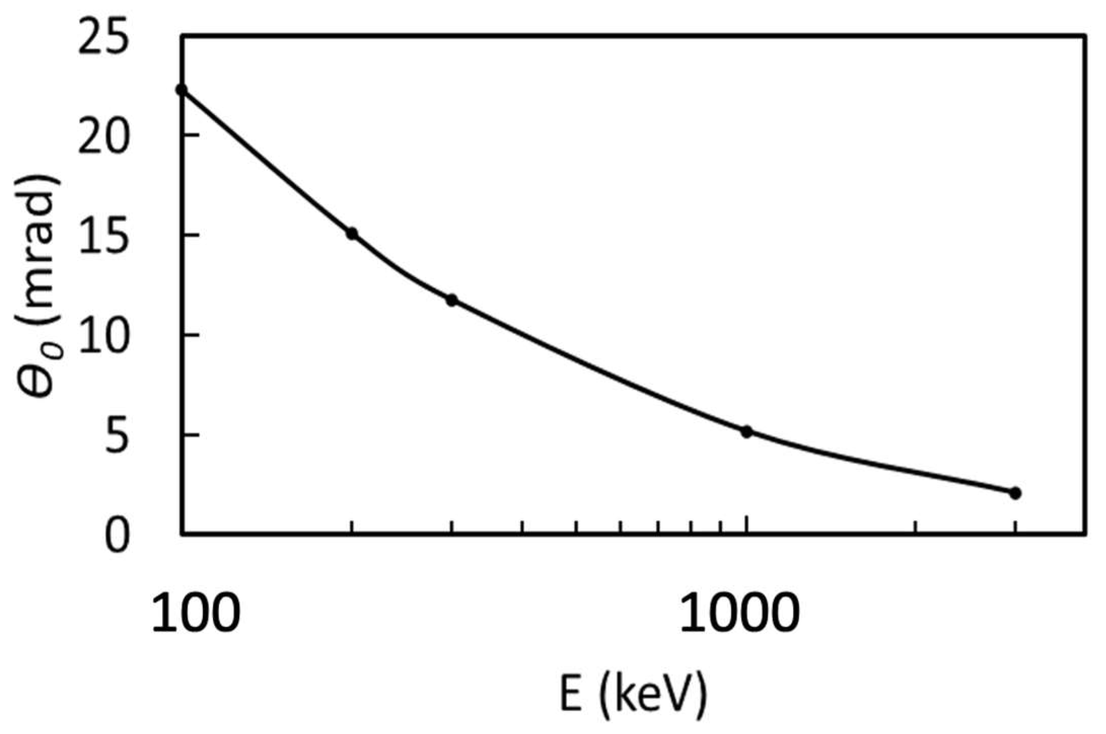
Figure 1. Characteristic angle of elastic scattering (q0) as a function of the beam energy.
Applsci 14 01888 g001
Figure 2. Electron beam profile in vacuum. (A) Trajectories of 10,000 electrons with a 1 nm radius and 1 mrad semi-convergence angle. (B,C) The calculated transverse beam profiles for depths up to 10 μm and 1 μm. (D) Beam radius R0.68, containing 68% of the electrons, as a function of sample depth. As a reference, the geometric beam broadening is shown in a black dashed line. The dimensional values in (AC) are in nm.
Applsci 14 01888 g002
Figure 3. Electron beam profile in amorphous ice at incident electron energies of 300 keV. (A) Trajectories of 10,000 electrons for depths up to 1 μm. (B) Trajectories of 4722 electrons collected within 0–10 mrad. (C) Beam radius R0.68 as a function of sample depth. As a reference, the geometric beam broadening is shown in a black dashed line. (D,E) The calculated transverse beam profiles of 10,000 electrons and 4722 electrons collected within 0–10 mrad for depths up to 1 μm. (F) Electrons scattered in ice as a function of depth, including single elastic, plural elastic, and inelastic scattering. The dimensional values in (A,B) and (D,E) are in nm.
Applsci 14 01888 g003
Figure 4. Electron beam profile in amorphous ice at incident electron energies of 3 MeV at a depth of 5 μm. (A) Trajectories of 10,000 electrons for depths up to 5 μm. (B) Trajectories of 6708 electrons collected within 0–10 mrad. (C) Beam radius R0.68 as a function of sample depth. (D,E) The calculated transverse beam profiles of 10,000 electrons and 6708 electrons collected within 0–10 mrad for depths up to 5 μm. (F) Electrons scattered in ice as a function of depth, including single elastic, plural elastic, and inelastic scattering. The dimensional values in (A,B) and (D,E) are in nm.
Applsci 14 01888 g004
Figure 5. Electron beam profile in amorphous ice at incident electron energies of 3 MeV at a depth of 10 μm. (A) Trajectories of 10,000 electrons for depths up to 10 μm. (B) Trajectories of 4187 electrons collected within 0–10 mrad. (C) Beam radius R0.68 as a function of sample depth. (D,E) The calculated transverse beam profiles of 10,000 electrons and 4187 electrons collected within 0–10 mrad for depths up to 10 μm. (F) Electrons scattered in ice as a function of depth, including single elastic, plural elastic, and inelastic scattering. The dimensional values in (A,B) and (D,E) are in nm.
Applsci 14 01888 g005
Figure 6. Effect of collection angle on beam width (A) and electron intensity (B).
Applsci 14 01888 g006
Figure 7. Effect of imaging modes on beam width at a depth of 5 μm (A) and 10 μm (B).
Applsci 14 01888 g007
Table 1. Electron scattering cross-section for Oxygen-only H2O from 100 keV to 3 MeV. θ 0 and θ E are the characteristic scattering angles for elastic and inelastic scattering.
Elastic Cross-Section (nm2) Inelastic Cross-Section (nm2)
Detector Collection Angle Detector Collection Angle
Electron Energy (eV)θ0 (mrad)0–10 mrad10–50 mrad50–100 mradTotalθE (mrad)0–10 mrad10–50 mrad50–100 mradTotal
100,00022.31.7 × 10−56.7 × 10−51.6 × 10−51.0 × 10−40.2141.6 × 10−43.1 × 10−52.4 × 10−61.9 × 10⁻⁴
200,00015.11.9 × 10−53.8 × 10−55.1 × 10−66.2 × 10−50.1141.1 × 10−41.2 × 10−56.9 × 10−71.3 × 10⁻⁴
300,00011.82.1 × 10−52.6 × 10−52.6 × 10−65.0 × 10−50.0809.4 × 10−56.8 × 10−63.4 × 10−71.0 × 10⁻⁴
1,000,0005.22.7 × 10−56.8 × 10−63.6 × 10−73.4 × 10−50.0295.9 × 10−51.1 × 10−64.6 × 10−86.0 × 10⁻⁵
3,000,0002.12.9 × 10−51.3 × 10−65.5 × 10−83.1 × 10−50.0114.1 × 10−51.7 × 10−76.9 × 10−94.1 × 10⁻⁵
Disclaimer/Publisher’s Note: The statements, opinions and data contained in all publications are solely those of the individual author(s) and contributor(s) and not of MDPI and/or the editor(s). MDPI and/or the editor(s) disclaim responsibility for any injury to people or property resulting from any ideas, methods, instructions or products referred to in the content.