
Operation Optimization of a Bucket Conveyor Transporting Wastes in the Processing Plant of a Hard Coal Mine


Abstract
1. Introduction
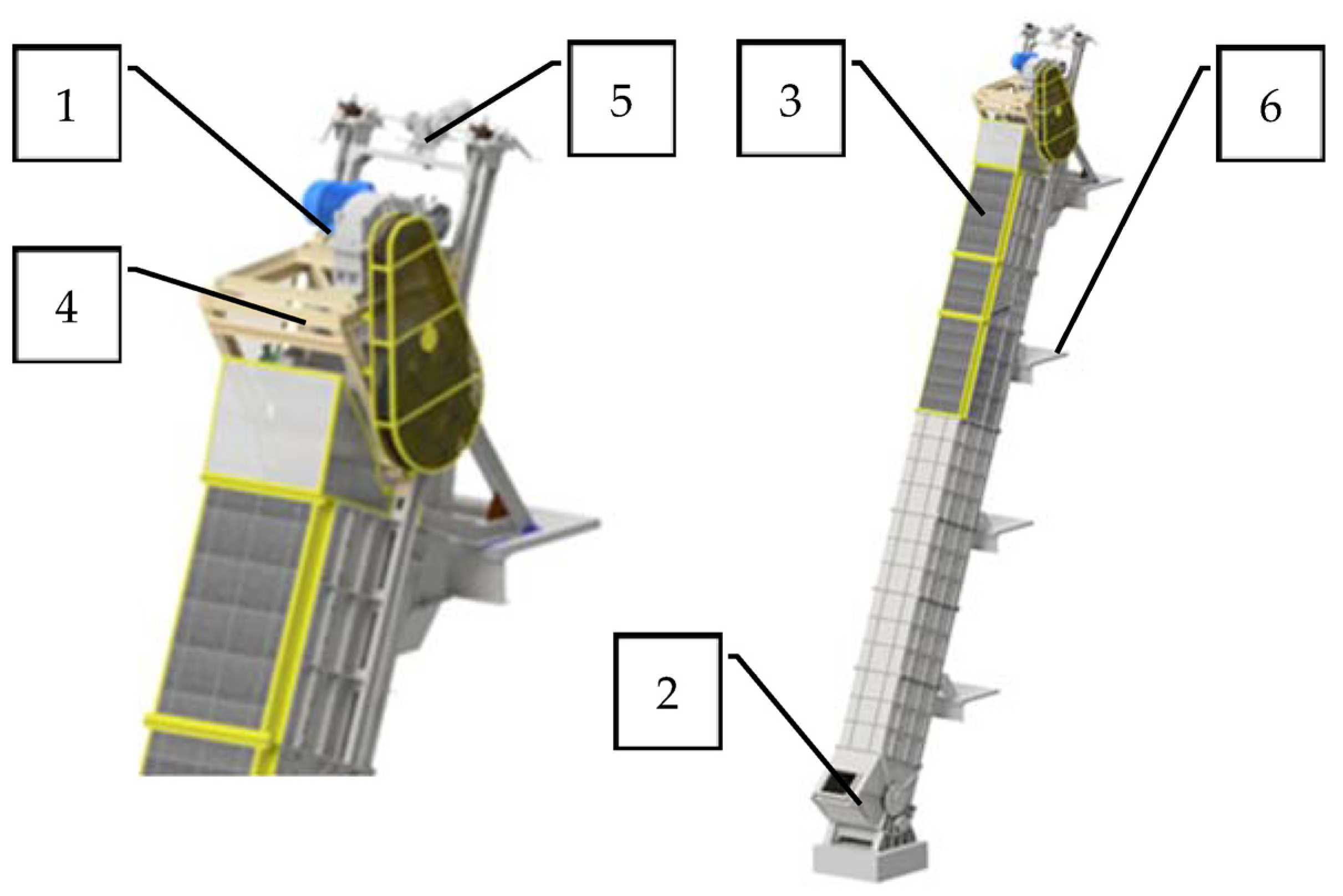
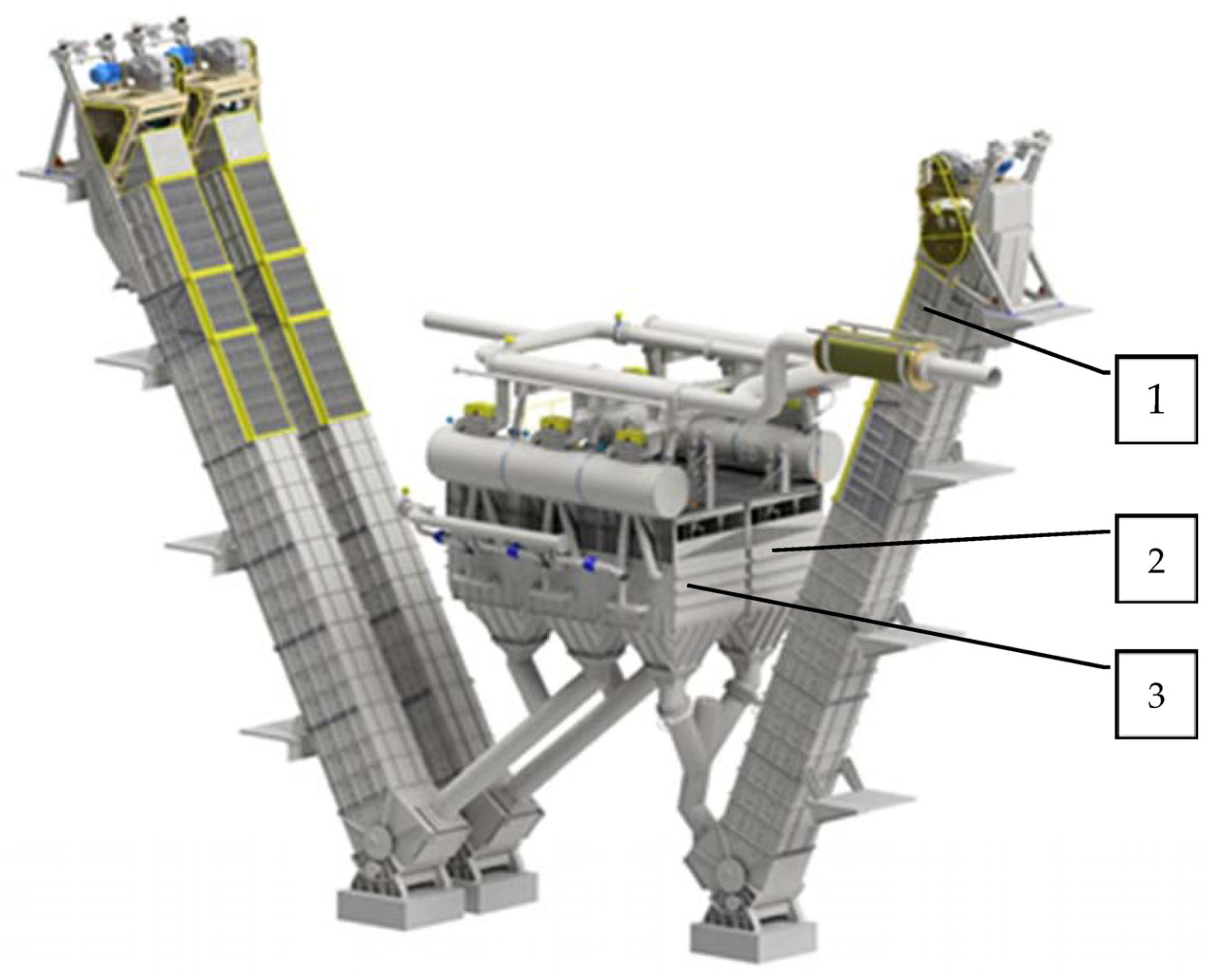
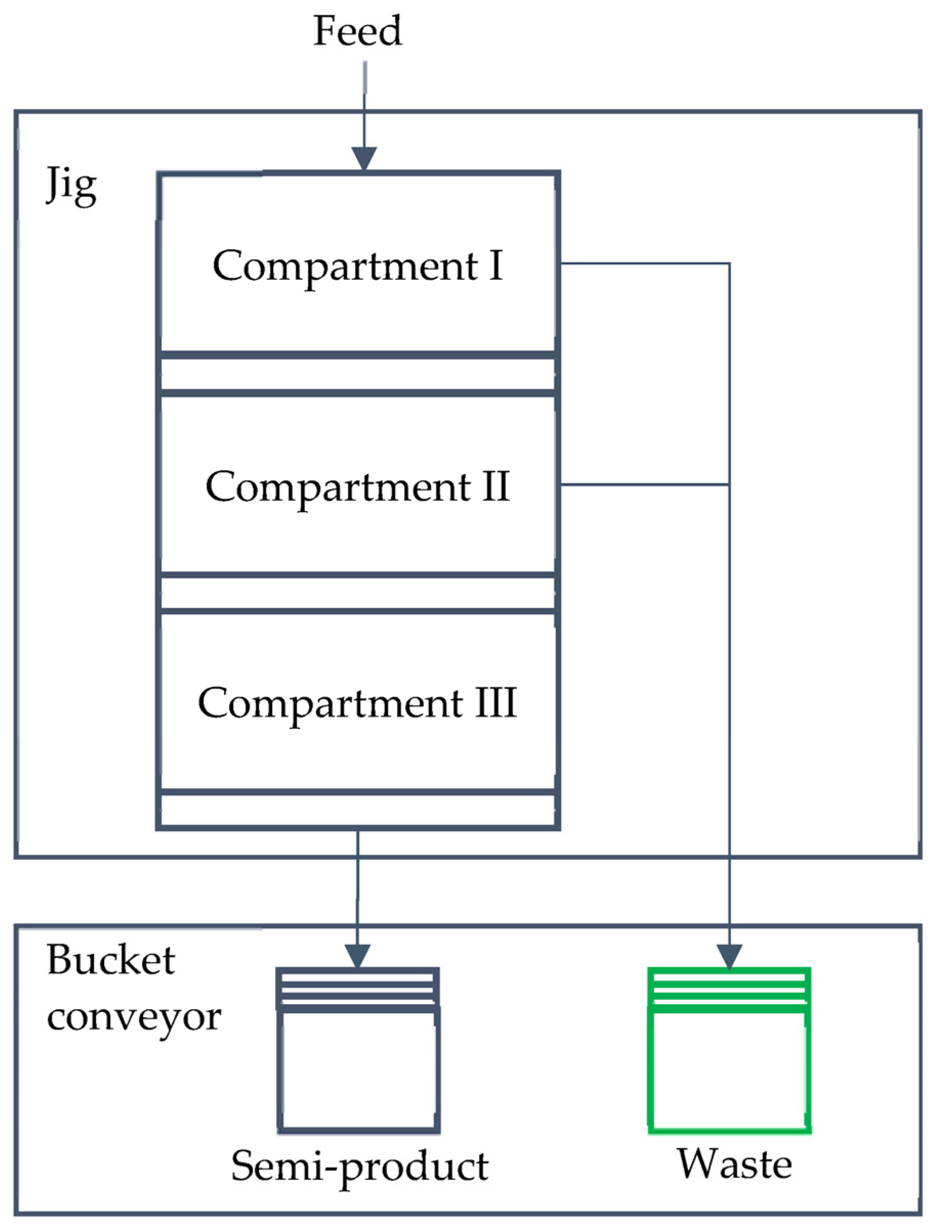
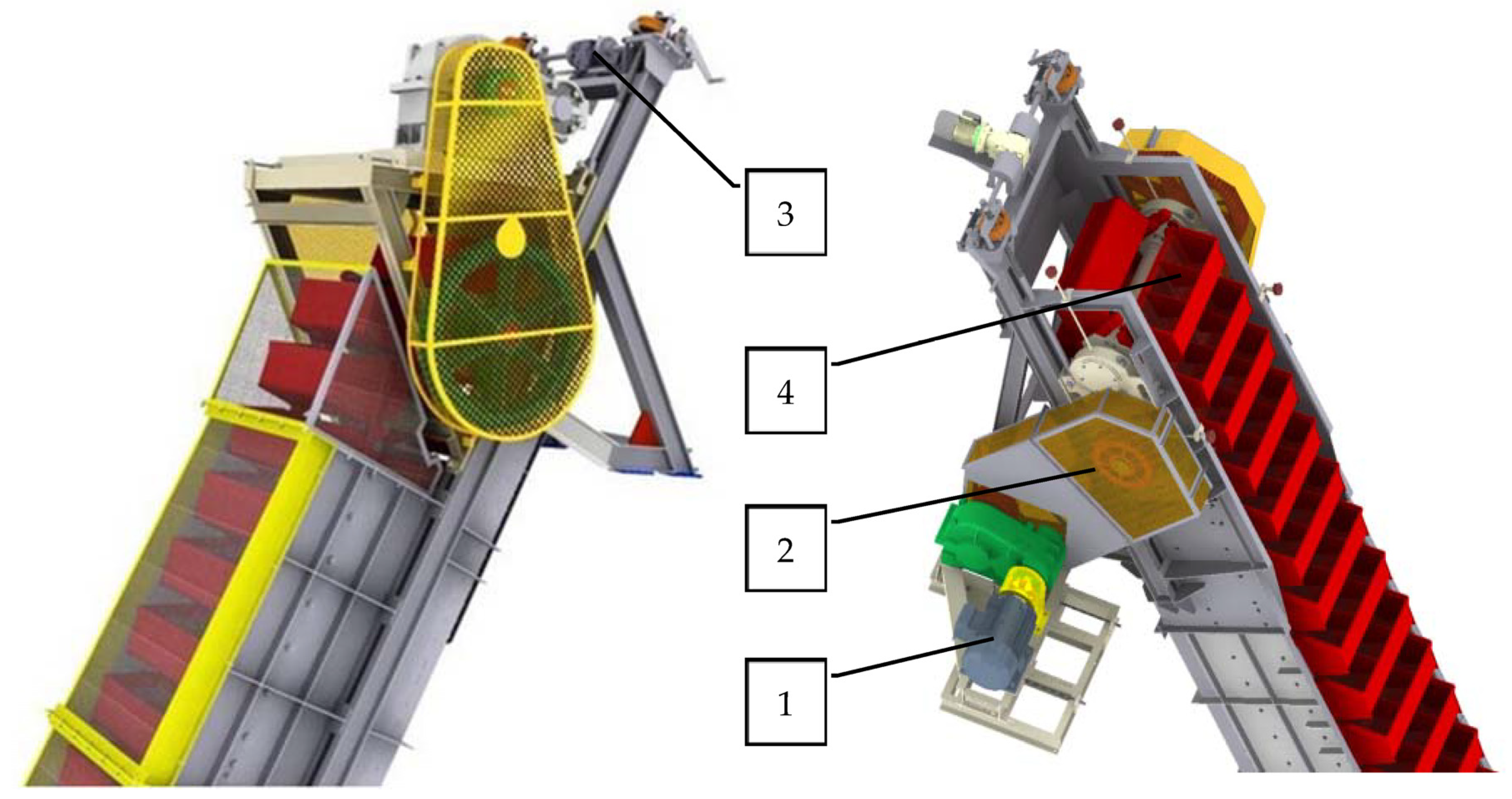
2. Design and Characteristics of Bucket Conveyor Operation
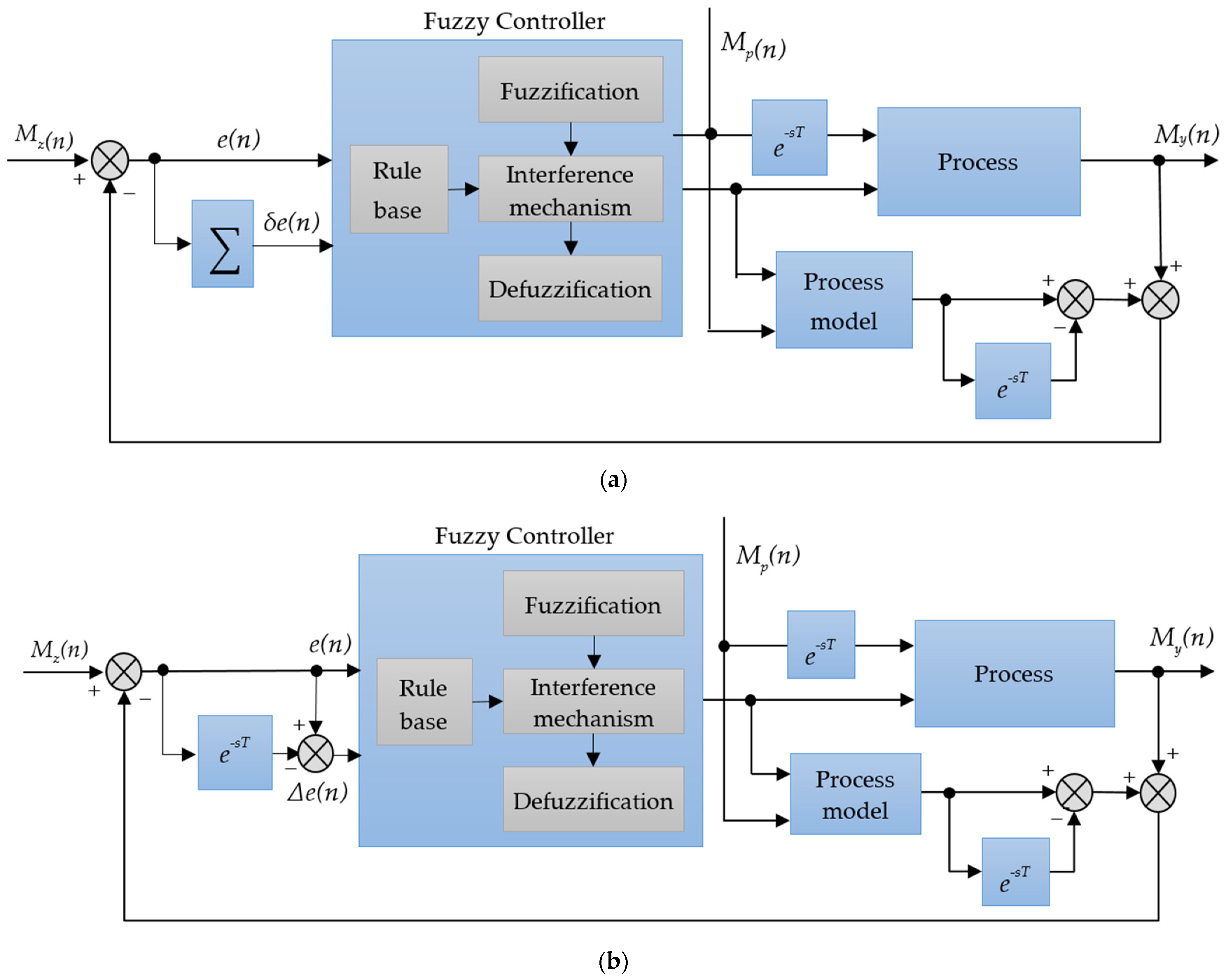
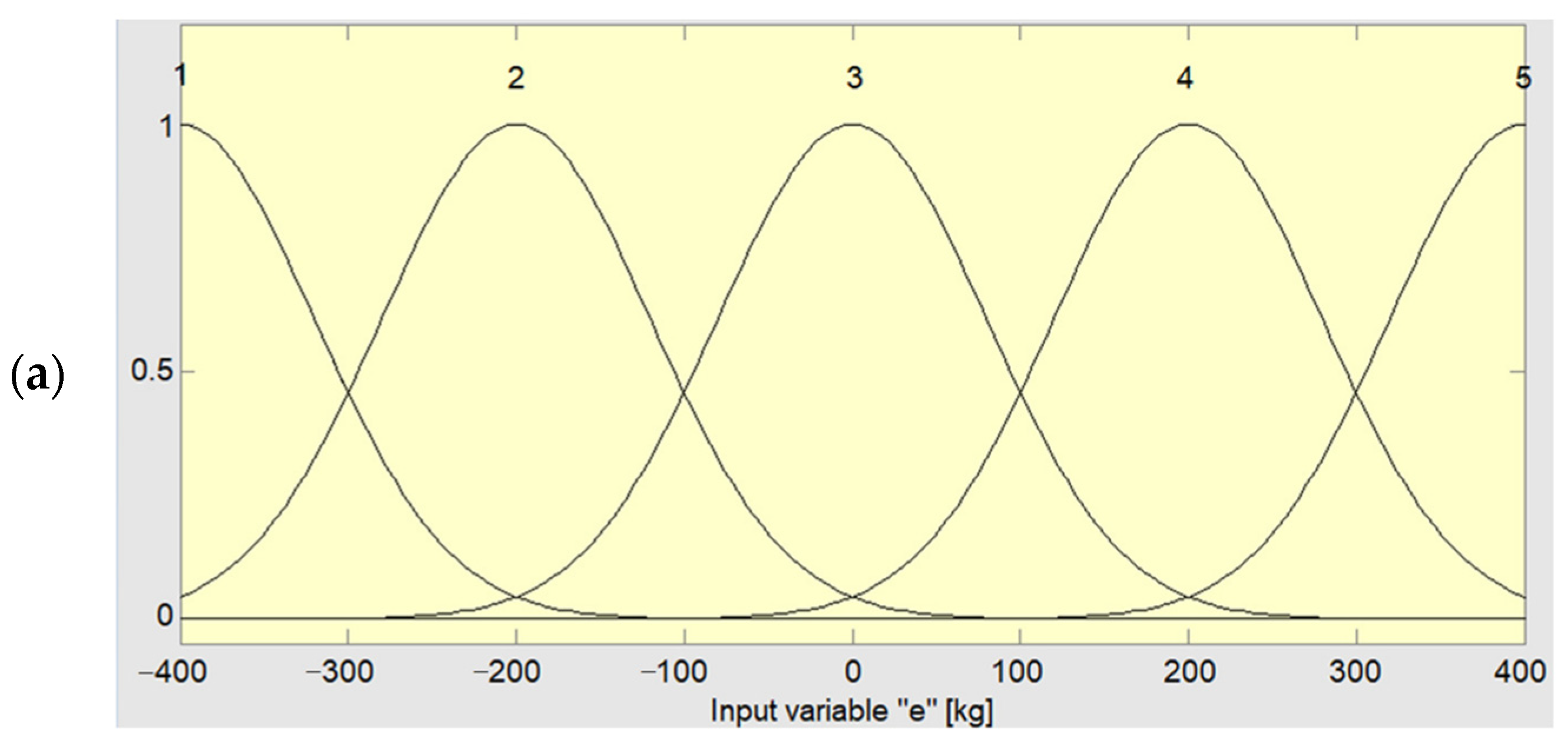
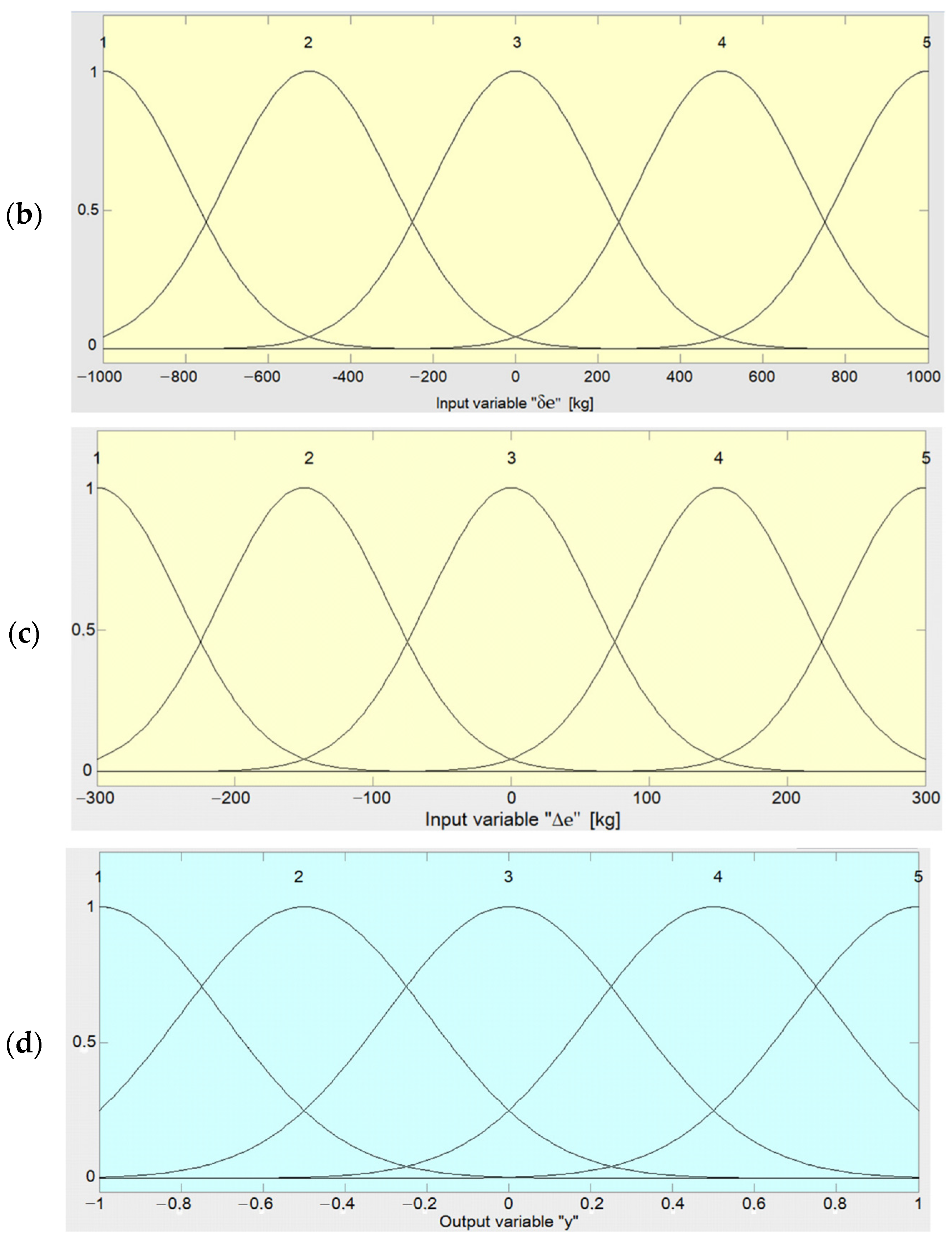
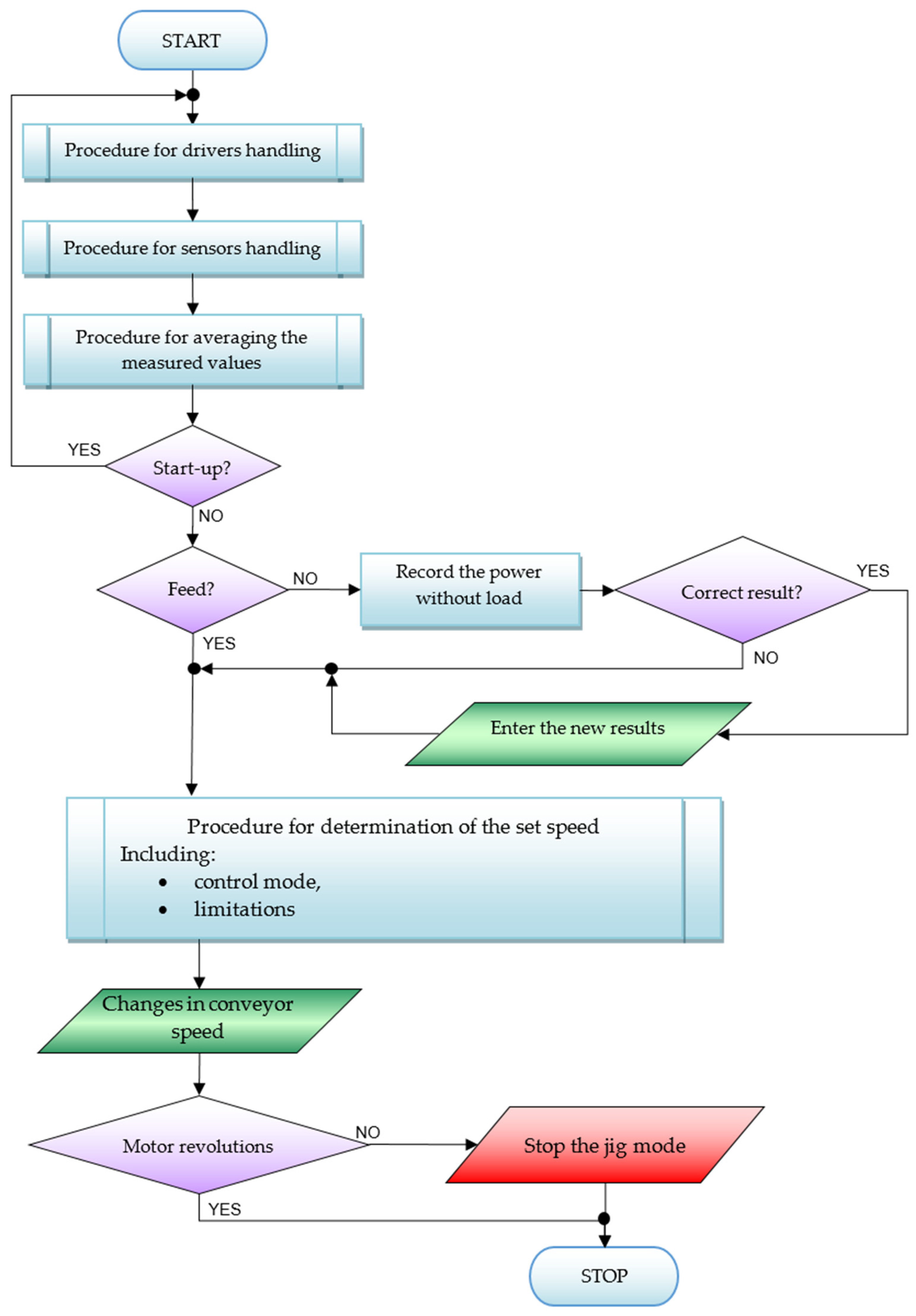
3. The Conveyor Speed Control System with Fuzzy Controller
- m—mass of transported material [kg],
- ∆P—difference in power drawn from the power grid when operating with load and
- without load [W],
- v—linear speed of buckets [m/s],
- α—angle of inclination of the bucket conveyor (α = 60°),
- g—acceleration due to gravity (g = 9.81m/s),
- µ—resistance of movement (µ = 0.2),
- η—motor efficiency (η = 0.81).
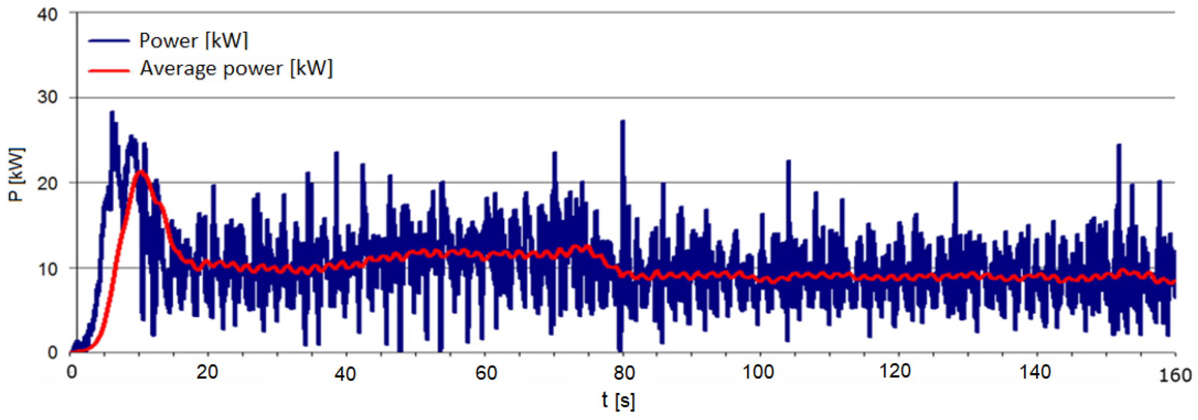
- pel—electric power [W],
- n0—the last recorded value,
- N—number of samples to be averaged (averaging period).
- u1(i)—discrete sequence of opening values of the discharge flaps,
- u2(i)—discrete sequence of conveyor speeds,
- y1(i)—discrete sequence of values of the average material weight on the conveyor,
- e(i)—white noise.
4. Simulation Tests of the Fuzzy Control System with Smith’s Predictor
- —mean value of a control error,
- e(i)—discrete sequence of values constituting the control signal error.
- e(i)—control signal error.
5. Industrial Tests of Fuzzy Logic Control System
- y(i)—the conveyor motor power supply frequency [Hz] (conveyor speed),
- u1(i)—the sum of the degrees of opening of discharge flaps in the jig compartments I and II [%],
- u11(i)—the degree of opening of the discharge flap in the jig compartment I [%],
- u12(i)—the opening degree of the discharge flap of the jig compartment II [%],
- A—a set of relationships meeting that result in setting the maximum conveyor speed,
- B—a set of relationships meeting that result in setting the minimum conveyor speed.
6. Conclusions
- The linear model in the form of an operator transfer function was suggested to describe the dynamics of the conveyor load as a response to a change in the intensity of the bottom product stream leaving the jig. The tests showed that the adopted structure of the control system with such a model reflects the dynamics of the facility well.
- Since the modeled process is in fact non-linear, and its output (mass of the transported material on the conveyor) is affected by a number of other parameters, a significant decrease in model compliance can be expected as we move away from the operating point that was established when determining the model parameters. However, this does not limit the usefulness of the presented object control model, which was confirmed by the test results.
- In the control system with a fuzzy controller, a smaller control error was observed than in the case of a PID controller. This proves the correct operation of the system in steady states, in which the material flow rate is stable.
- The integral time square error determined in the system with a fuzzy controller is smaller, which proves that this controller has better dynamics compared to the PID controller, resulting in the transient waveform disappearing faster.
- In the case of large disturbances in feeding the material into the conveyor, the control signal becomes saturated, which causes overshoots and worsens the control effects. This was seen when using both the fuzzy controller and the PID controller.
- Further analysis is justified for the effects of using the algorithms with various methods of compensating unfavorable phenomena accompanying the control of non-linear processes.
- Further tests will include a more detailed analysis of the system with a fuzzy controller, taking into account such disturbances as changes in the feed flow rate. Successful tests will allow implementation of a fuzzy controller to control bucket conveyor operation. Using other structures for testing the control systems is planned, e.g., the Reswick controller or MFC robust control systems. Another possibility is to use a non-linear model. However, this may require the use of a PLC controller with greater computing power, or the use of an independent controller in relation to the controller that manages jig node operations. This approach may turn out to be economically unprofitable.
Author Contributions
Funding
Institutional Review Board Statement
Informed Consent Statement
Data Availability Statement
Conflicts of Interest
Appendix A

References
- Blaschke, W. Przeróbka Węgla Kamiennego—Wzbogacanie Grawitacyjne; Wydawnictwo Instytutu Gospodarki Surowcami Mineralnymi i Energią PAN: Kraków, Poland, 2009. [Google Scholar]
- Ma, F.; Xiong, F.; Li, G. Key Structure Innovation and Optimization Design of Bucket Elevator. In Advanced Manufacturing and Automation VIII; Wang, K., Wang, Y., Strandhagen, J., Yu, T., Eds.; IWAMA 2018; Lecture Notes in Electrical Engineering (2019); Springer: Singapore, 2019; Volume 484. [Google Scholar]
- Wójcicki, M.; Wieczorek, A.N.; Głuszek, G. Concept of the facility for testing the wear of chain links in the aspect of synergism of environmental factors. Min. Mach. 2021, 39, 71–81. [Google Scholar]
- Dolipski, M.; Remiorz, E.; Sobota, P. Determination of dynamic loads of sprocket drum teeth and seats using mathematical model of a scraper conveyor. Arch. Min. Sci. 2012, 57, 1101–1119. [Google Scholar]
- Jeftenić, B.; Ristić, L.; Bebić, M.; Štatkić, S.; Mihailović, I.; Jevtić, D. Optimal Utilization of the Bulk Material Transportation System based on Speed Controlled Drives. In Proceedings of the XIX International Conference on Electrical Machines ICEM 2010, Rome, Italy, 6–8 September 2010; pp. 1–6. [Google Scholar]
- Beldzik, J.; Głowiak, S.; Głowiak, Ł.; Grabowski, M.; Svach, J. The Method of Adjusting the Bucket Filling. Patent Description PL217351B1, 12 November 2013. (In Polish). [Google Scholar]
- Kost, G.; Jendrysik, S.; Sękała, A. Identification of the Mathematical Model of the Bucket Conveyor. In Modelling in Engineering 2020: Applied Mechanics, SMWM 2020, Advances in Intelligent Systems and Computing; Springer: Cham, Switzerland, 2021; Volume 1336, pp. 155–167. ISBN 978-3-030-68454-9. [Google Scholar] [CrossRef]
- Li, H.-X.; Gatland, H.B. A new methodology for designing a fuzzy logic controller. IEEE Trans. Syst. Man Cybern. 1995, 35, 505–512. [Google Scholar]
- Malec, M.; Stańczak, L. Innovative Mining Techniques and Technologies Review of Selected KOMTECH-IMTech 2019 Conference Proceedings Part 2. Min. Mach. 2020, 2, 13–25. [Google Scholar]
- Stankiewicz, K. Mechatronic systems developed at the KOMAG. Min. Mach. 2020, 2020, 58–68. [Google Scholar]
- Fan, X.; Zhang, N.; Li, N. Structure analysis of typical fuzzy controllers with unequally spaced fuzzy sets for input and output variables. Chin. J. Electron. 2001, 10, 326–331. [Google Scholar]
- Hubert, W.; Gutorski, Z.; Badura, A.; Lipka, B. Bucket Conveyor Catalog; ITG KOMAG: Gliwice, Poland, 1982; (unpublished materials). [Google Scholar]
- Korupu, V.L.; Muthukumarasamy, M. A comparative study of various Smith predictor configurations for industrial delay processes. Chem. Prod. Process Model. 2021, 17, 701–732. [Google Scholar] [CrossRef]
- Zheng, M.; Huang, T.; Zhang, G. A New Design Method for PI-PD Control of Unstable Fractional-Order System with Time Delay. Complexity 2019, 2019, 3253497. [Google Scholar] [CrossRef]
- Tu, K.Y.; Lee, T.T.; Wang, W.J. Design of a multi-layer fuzzy logic controller for multi-input multi-output systems. Fuzzy Sets Syst. 2000, 111, 199–214. [Google Scholar] [CrossRef]
- de Almeida Souza, D.; de Aragao Filho, W.C.; Sousa, G.C.D. Adaptive fuzzy controller for efficiency optimization of induction motors. IEEE Trans. Ind. Electron. 2007, 54, 2157–2164. [Google Scholar] [CrossRef]
- Optimization Toolbox User’s Guide for Use with MATLAB, Version 2. Available online: www.mathworks.com (accessed on 7 November 2023).


| Δy | E | |||||
|---|---|---|---|---|---|---|
| 1 | 2 | 3 | 4 | 5 | ||
| E’ | 1 | 1 | 1 | 2 | 3 | 3 |
| 2 | 1 | 1 | 3 | 3 | 3 | |
| 3 | 1 | 2 | 3 | 4 | 4 | |
| 4 | 1 | 3 | 3 | 5 | 5 | |
| 5 | 2 | 2 | 4 | 5 | 5 | |
| FUZZY PI | 130.66 | 356375893 |
| FUZZY PD | 131.79 | 369961286 |
| Variant | PID | Fuzzy |
|---|---|---|
| [kg] | [kg] | |
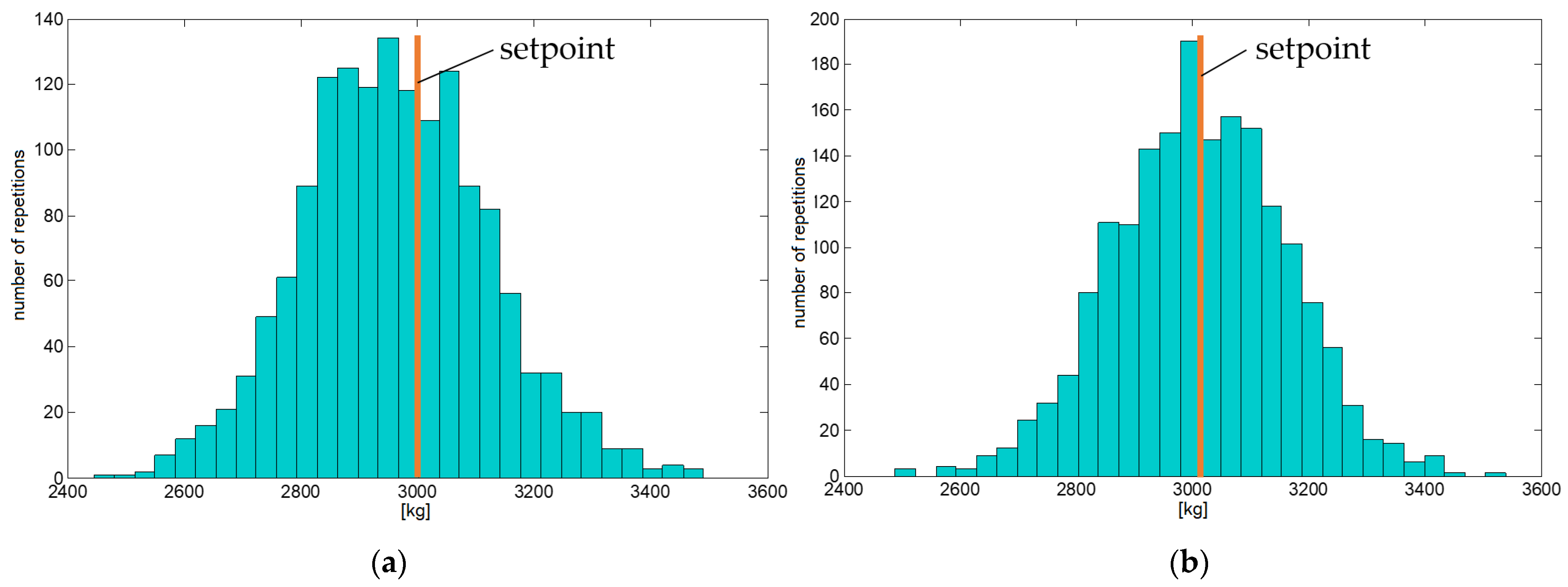
| Mean value | 2934 | 3023 |
| Standard deviation | 159.8 | 148.3 |
Disclaimer/Publisher’s Note: The statements, opinions and data contained in all publications are solely those of the individual author(s) and contributor(s) and not of MDPI and/or the editor(s). MDPI and/or the editor(s) disclaim responsibility for any injury to people or property resulting from any ideas, methods, instructions or products referred to in the content. |
© 2024 by the authors. Licensee MDPI, Basel, Switzerland. This article is an open access article distributed under the terms and conditions of the Creative Commons Attribution (CC BY) license (https://creativecommons.org/licenses/by/4.0/).
Share and Cite
Jendrysik, S.; Rogala-Rojek, J.; Kowol, D.; Wieczorek, A.N. Operation Optimization of a Bucket Conveyor Transporting Wastes in the Processing Plant of a Hard Coal Mine. Appl. Sci. 2024, 14, 1764. https://doi.org/10.3390/app14051764
Jendrysik S, Rogala-Rojek J, Kowol D, Wieczorek AN. Operation Optimization of a Bucket Conveyor Transporting Wastes in the Processing Plant of a Hard Coal Mine. Applied Sciences. 2024; 14(5):1764. https://doi.org/10.3390/app14051764
Chicago/Turabian StyleJendrysik, Sebastian, Joanna Rogala-Rojek, Daniel Kowol, and Andrzej N. Wieczorek. 2024. "Operation Optimization of a Bucket Conveyor Transporting Wastes in the Processing Plant of a Hard Coal Mine" Applied Sciences 14, no. 5: 1764. https://doi.org/10.3390/app14051764
APA StyleJendrysik, S., Rogala-Rojek, J., Kowol, D., & Wieczorek, A. N. (2024). Operation Optimization of a Bucket Conveyor Transporting Wastes in the Processing Plant of a Hard Coal Mine. Applied Sciences, 14(5), 1764. https://doi.org/10.3390/app14051764