Abstract
To clarify the mechanics of tooth movement produced by a unique distalizer, Class II Carriere Motion appliance (CMA), in which the maxillary canine is connected to the maxillary first molar with a stiff bar, long-term tooth movement was simulated by the finite element method (FEM). The FEM models of the maxillary canine, premolars, and first molar were made based on a dental study model. The periodontal ligament (PDL) was constructed on the root and assumed to be a nonlinear elastic material. The teeth and the alveolar bone were assumed to be rigid bodies. The tooth moved by accumulating the initial movement produced by the elastic deformation of the PDL. When retraction force was applied to the canine from the mandibular dentition, the canine tipped or rotated clockwise and extruded due to the vertical component of the retraction force. The molar and premolars also tipped and moved distally, but hardly extruded because the vertical force did not act on them. As a result of these tooth movements, the canine protruded from the dentition. An interproximal space was created between the canine and the lateral incisor. These movement patterns were similar to those in other clinical studies using the CMA.
1. Introduction
Distal movement of the molars has often been used to improve the occlusal relationship of the molars or to create the space required for tooth alignment [1]. To move the molar distally, various methods, including headgear, have been used until now [2]. At present, orthodontic anchor screws are frequently used as absolute anchorage. However, the placement of the anchor screw is a surgical treatment and has a burden for the patient [3].
Class II Carriere Motion appliance (CMA) is a maxillary molar distalizing device developed by Dr. Carriere [4,5], which consists of distal and mesial bracket pads connected by a rigid bar. The distal bracket pad is connected to the maxillary first molar with a ball-and-socket joint, allowing three-dimensional rotation of the molar. The mesial pad is bonded on the maxillary canine in the standard CMA, and on the maxillary first premolar in the shorty CMA. To move the posterior maxillary segment, distal force is applied to the mesial bracket with Class II elastics from the mandibular dentition.
Because the CMA is bonded to only two posterior teeth, its placement is more convenient than that in conventional Class II intermaxillary elastics, in which all maxillary teeth are connected to an archwire through brackets. Further, the CMA does not cover the incisors and therefore has an aesthetic advantage over the Class II intermaxillary elastics. A transparent retainer or aligner is often placed on the mandibular dentition, which is used as anchorage.
Previous clinical studies have shown that CMA was effective in improving Class II malocclusions [6,7]. In addition, tooth movement patterns were measured precisely using cone beam computed tomography (CBCT) [8,9].
However, few studies have examined CMA from a mechanical point of view. The mechanics of CMA has not been clarified. In the present study, distalization of the maxillary molar with the standard CMA was simulated using the finite element method (FEM), and their results were compared with the tooth movement observed in other clinical studies.
2. Materials and Methods
2.1. FEM Model
Figure 1 shows the FEM model for simulating orthodontic tooth movements. To construct this model, the same method employed in previous articles was used [10,11,12]. Only the right side was modeled due to the bilateral symmetry of the dentition. The standard CMA was connected to the maxillary right canine and first molar. The FEM models of the teeth were made based on a dental study model (i21D-400C, Nisshin Dental Products Inc., Kyoto, Japan) [11]. The teeth were assumed to be rigid bodies, and their surfaces were meshed into shell elements [11].
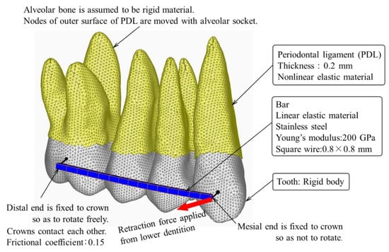
Figure 1.
Finite element model for simulating tooth movement by CMA.
The periodontal ligament (PDL) of 0.2 mm thickness was constructed on the root and meshed into three-dimensional solid elements. The PDL was assumed to be a nonlinear elastic material whose stress–strain curve was approximated by multiple connected lines. By using this elastic property of the PDL, the mobility of the maxillary first premolar could be simulated by the FEM [11]. The alveolar bone was assumed to be a rigid body because Young’s modulus (about 10 GPa) was extremely larger than that of the PDL [13]. This assumption allows us to exclude the alveolar bone from the FEM model.
The bar was 0.8 mm square in cross-section and made of stainless steel whose Young’s modulus was 200 GPa. The bar was meshed into beam elements. A mesial end of the CMA was fixed to the canine crown so as not to rotate. A distal end of the CMA was connected to the molar crown with a pin joint, on which the molar rotated freely. This connection simulated a ball-and-socket joint.
Contact elements were overlaid on the crown surfaces to prevent penetrations into each other. The frictional coefficient of the crown surface was 0.15.
A distal retraction force of 1.8 N was applied to the canine from the mandibular first molar.
2.2. Simulation for Long-Term Tooth Movement
To simulate orthodontic tooth movement, we used the same method as in previous articles [10,11,12], in which the tooth was assumed to move in the same direction as that in the initial movement produced by elastic deformation of the PDL.
The alveolar socket, which coincided with the external surface of the PDL, was moved in the same direction and the same amount as those in the initial movement. The simulation method was constructed of the following three steps. Firstly, a force was applied to the CMA. Second, the initial movement of each tooth was calculated. Third, the alveolar socket of each tooth was moved in the same direction and the same amount as the initial movement. Repeating the second and third steps, the teeth moved step by step. At each step, the forces and moments acting on the teeth were updated. The number of repeating calculations, n, corresponded to an elapsed time after the force application. However, the n could not be converted into an actual time. A FEM software ANSYS 16.2 (ANSYS Inc., Canonsburg, PA, USA) was used for the simulations.
3. Results
In the FEM simulation, the molar moved distally 1.86 mm at the number of repetitions n = 120. This amount of movement is about the same as those in clinical studies [8,9]. The movement pattern of the teeth at n = 120 is shown in Figure 2, in which the initial position of the teeth is depicted in a light gray color. The mean stress in the PDL is shown with color contours, in which compressive and tensile stresses are indicated in red and blue colors, respectively. The incisors, which were not included in the FEM model, are drawn to indicate their locations in the maxillary dentition.
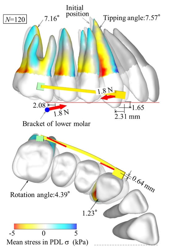
Figure 2.
Tooth movement pattern when canine moves distally about 2 mm (n = 120).
The first molar tipped, rotated, and moved distally. The canine tipped, moved distally, and protruded from the maxillary dentition. An interproximal space was created between the canine and the lateral incisor. The premolars, which were not connected to the CMA, were tipped distally in contact with the adjacent tooth. All the teeth were tipped, which gave rise to compressive stress near the cervical region and tensile stress near the root apex on the distal side of the roots.
4. Discussion
4.1. Mechanics of Tooth Movement
The mesial end of the CMA was fixed to the canine so as not to rotate, but the distal end was connected to the molar with a rotatable ball-and-socket joint. When retraction force was applied to the canine from the mandibular dentition, the CMA and the canine tipped or rotated clockwise in a body around the distal end (Figure 2). In addition, the canine extruded due to the vertical component of the retraction force. The molar and premolars also tipped and moved distally, but hardly extruded because the vertical force did not act on them. As a result of these tooth movements, the canine protruded from the dentition.
In clinical settings, the protrusion of the canine from the dentition is an undesirable movement except in cases where the canine is depressed before treatment. On the other hand, in the case where the maxillary dentition is distalized with conventional Class II intermaxillary elastics, the anterior teeth are extruded, but the canine protrusion does not occur [14]. The CMA is not the best device to use in all cases and should be selected depending on the individual patient.
In the occlusal plane, the rotation of the canine was small due to constraints by the CMA. On the other hand, since the molar was connected to the CMA with the rotatable joint, the rotational angle of the molar was greater than that of the canine. This rotation resulted in some distal movement of the buccal cusp of the molar, which would contribute to the improvement of Class II malocclusion [6,7]. It has also been reported that the buccal cusp of the molar is often rotated mesially in malocclusions [15]. In such cases, the distal rotation of the molar will be effective in correcting the malocclusion.
The mandibular dentition, which is placed in an aligner or fixed to a lingual arch, moves mesially and rotates clockwise by the mesial retraction force applied to the mandibular first molar from the maxillary canine [16]. This movement corrects the Class II occlusal relationship between the upper and lower molars. The mandibular incisors are intruded by the rotation of the mandibular dentition, while the maxillary incisors do not move, as shown in Figure 2, which may cause an open bite.
4.2. Comparison with Clinical Study
In clinical studies, CMA is used to improve molar occlusion, followed by treatment with a wire-bracket appliance. The time required to correct Class II malocclusion was measured to be 5.2 [6] or 6.3 months [7]; that is, the CMA was effective in reducing treatment time. One reason may be caused by the tipping movement of the teeth. However, in the study by Yin et al. [7], the total treatment time including wire-bracket appliance was prolonged probably due to various side effects of CMA, such as extrusion of canines and extra space distal to the lateral incisors. The mechanism of these side effects was clarified by the present FEM simulation.
Tooth movements produced by CMA have been measured precisely using CBCT [8,9]. The present FEM model corresponds to the standard CMA in the study by Wilson et al. [9]. Their measured values are cited in Table 1 and compared with those in the present FEM simulation, in which distal movement, distal tipping angle, extrusion, and rotational angle in the occlusal plane of the maxillary canines (U3), first premolar (U4), and molar (U6) were measured before and after wearing the CMA for Class II malocclusion. The distal movement and extrusion were measured at the canine cusp, the first premolar buccal cusp, and the molar mesiobuccal cusp. In the clinical study, all values of axial rotation angles were statistically insignificant [9].

Table 1.
Comparison between FEM simulation and a clinical study.
The clinical study showed that the maxillary canines moved with distal tipping, rotation, and extrusion (Table 1). The molars also moved with distal tipping. Such movement types could be simulated by the FEM (Figure 2). The amounts of tooth movements in the FEM simulation were within the range of those in the clinical study (Table 1). However, in the canine, the amount of distal movement and rotation was smaller than those measured in the clinical study. The reason for this difference could not be clarified, but it is probably due to the FEM model of the teeth, which affected the quantitative results in the simulation.
5. Conclusions
The FEM simulation visually clarified the features of tooth movement produced by the CMA; that is, the maxillary canine, premolar, and molar were tipped and moved distally. The canine protruded from the dentition. These movement patterns, which occurred according to the laws of mechanics, were similar to those in other clinical studies using the CMA.
Author Contributions
Conceptualization: Y.Y.; methodology: Y.Y.; validation: T.T., J.K.K., and N.O.; investigation: J.K.K.; data curation: T.T.; writing—original draft preparation: Y.Y.; writing—review and editing: Y.Y.; supervision: N.O.; project administration: Y.Y. All authors have read and agreed to the published version of the manuscript.
Funding
This research received no external funding.
Institutional Review Board Statement
Not applicable.
Informed Consent Statement
Not applicable.
Data Availability Statement
Data are contained within the article.
Acknowledgments
The authors thank Yukio Kojima for valuable advice and support with the finite element analysis.
Conflicts of Interest
An author, John K. Kaku has received honoraria for speaking at the seminar on CMA. The other authors declare no conflict of interest.
References
- Yamada, K.; Kuroda, S.; Deguchi, T.; Takano-Yamamoto, T.; Yamashiro, T. Distal movement of maxillary molars using miniscrew anchorage in the buccal interradicular region. Angle Orthod. 2009, 79, 78–84. [Google Scholar] [CrossRef] [PubMed]
- Miyano, J.; Kawanabe, N.; Fujishiro, A.; Kanomi, R.; Kamioka, H. Simultaneous distal movement of the maxillary first and second premolars can be achieved by distal movement of the maxillary first molar using a headgear. Orthod. Waves 2020, 79, 171–178. [Google Scholar] [CrossRef]
- Miyazawa, K.; Shibata, M.; Tabuchi, M.; Kawaguchi, M.; Shimura, N.; Goto, S. Optimal sites for orthodontic anchor screw placement using panoramic images: Risk of maxillary sinus perforation and contact with adjacent tooth roots during screw placement. Prog. Orthod. 2021, 22, 46. [Google Scholar] [CrossRef] [PubMed]
- Carriere, L.A. New Class II Distalizer. J. Clin. Orthod. 2014, 38, 224–231. [Google Scholar]
- The CarriereⓇ Motion™ Workbook. Henry Schein Orthodontics. 2015. Available online: https://www.orthodent.de/images/pdf/motion/motion2workbooken.pdf (accessed on 6 February 2024).
- Kim-Berman, H.; McNamara, J.A., Jr.; Lints, J.P.; McMullen, C.; Franchi, L. Treatment effects of the Carriere Motion 3D appliance for the correction of Class II malocclusion in adolescents. Angle Orthod. 2019, 89, 839–846. [Google Scholar] [CrossRef] [PubMed]
- Yin, K.; Han, E.; Guo, J.; Yasumura, T.; Grauer, D.; Sameshima, G. Evaluating the treatment effectiveness and efficiency of Carriere Distalizer: A cephalometric and study model comparison of Class II appliances. Prog. Orthod. 2019, 20, 24. [Google Scholar] [CrossRef] [PubMed]
- Areepong, D.; Kim, K.B.; Oliber, D.R.; Ueno, H. The Class II Carriere Motion appliance: A 3D CBCT evaluation of the effects on the dentition. Angle Orthod. 2020, 90, 491–499. [Google Scholar] [CrossRef] [PubMed]
- Wilson, B.; Konstanton, N.; Kim, K.B.; Foley, P.; Ueno, H. Three-dimensional cone-beam computed tomography comparison of shorty and standard Class II Carriere Motion appliance. Angle Orthod. 2021, 91, 423–432. [Google Scholar] [CrossRef] [PubMed]
- Kojima, Y.; Fukui, H. Numerical simulation of canine retraction with T-loop spring based on the updated moment-to-force ratio. Eur. J. Orthod. 2012, 34, 10–18. [Google Scholar] [CrossRef] [PubMed]
- Park, J.H.; Kook, Y.A.; Kojima, Y.; Yun, S.; Chae, J.M. Palatal en-masse retraction of segmented maxillary anterior teeth: A finite element study. Korean J. Orthod. 2019, 49, 188–193. [Google Scholar] [CrossRef] [PubMed]
- Yokoi, Y.; Arai, A.; Kawamura, J.; Uozumi, T.; Usui, Y.; Okafuji, N. Effects of attachment of plastic aligner in closing of diastema of maxillary dentition by finite element method. J. Healthcare Eng. 2019, 2019, 1075097. [Google Scholar] [CrossRef] [PubMed]
- Chang, M.C.; Ko, C.C.; Liu, C.C.; Douglas, W.H.; DeLong, R.; Seong, W.J.; Hodges, J.; An, K.N. Elasticity of alveolar bone near dental implant-bone interfaces after one month’s healing. J Biomech. 2003, 36, 1209–1214. [Google Scholar] [CrossRef] [PubMed]
- Kawamura, J.; Park, J.H.; Kojima, Y.; Tamaya, N.; Kook, Y.A.; Kyung, H.M.; Chae, J.M. Biomechanical analysis for total distalization of the maxillary dentition: A finite element study. Am. J. Orthod. Dentofac. Orthop. 2021, 160, 259–265. [Google Scholar] [CrossRef] [PubMed]
- Giuntini, V.; Baccetti, T.; Defraia, E.; Cozza, P.; Franchi, L. Mesial rotation of upper first molars in Class II division 1 malocclusion in the mixed dentition: A controlled blind study. Prog. Orthod. 2011, 12, 107–113. [Google Scholar] [CrossRef] [PubMed]
- Kawamura, J.; Park, J.H.; Kojima, Y.; Kook, Y.A.; Kyung, H.M.; Chae, J.M. Biomechanical analysis for total mesialization of the mandibular dentition A finite element study. Orthod. Craniofac. Res. 2019, 22, 329–336. [Google Scholar] [CrossRef]
Disclaimer/Publisher’s Note: The statements, opinions and data contained in all publications are solely those of the individual author(s) and contributor(s) and not of MDPI and/or the editor(s). MDPI and/or the editor(s) disclaim responsibility for any injury to people or property resulting from any ideas, methods, instructions or products referred to in the content. |
© 2024 by the authors. Licensee MDPI, Basel, Switzerland. This article is an open access article distributed under the terms and conditions of the Creative Commons Attribution (CC BY) license (https://creativecommons.org/licenses/by/4.0/).