1. Introduction
Robots that coexist and collaborate closely with humans are expected to be intrinsically safe, i.e., they should not pose a higher risk of injury than when they collaborate with other minds. A significant ongoing development in robotics is to be found in the use of soft materials inspired by biology [
1,
2], exploiting softness and body compliance through the use of structurally deformable objects. Taking this a step further, the field of soft robotics adapts and shapes compliant structures in a manner that facilitates desired variable impedance characteristics [
3] as well as allowing for more energy-efficient interactions [
4]. Traditionally, rigid-bodied robots are mainly used in production lines, where a deterministic and singular task is performed, usually in an area closed off to humans. Thus, the emphasis is not on the notion of safe interaction with people. However, in the ongoing convergence of human and machine workspaces, the need to adapt the traditional paradigm in the development of human-centric robotic systems emerges. Della Santina et al. [
5] outlined the shift driven by soft robotics as progressing from a traditional “design for accuracy, control for safety” to a “design for safety, control for performance”.
Following this way of thinking, the development of compliant robotic structures comes naturally, using elastic materials [
6] such as silicones, rubbers, polyamides, or similar. Taking a cue from slender creatures such as snakes and octopuses, tendon-driven continuum joints use cylindrical, elastic materials that are deformed to control their shape or the position of their tip, see for example
Figure 1. In the latter case, the deformation is achieved by guided tendons, which, in contrast to rigid-body joints, cannot be described by a finite number of rotational axes [
7], but are usually approximated by finite element methods, state estimates [
7], modeling approaches [
8] or, in simple cases, analytical formulas [
9].
Industrial systems based on continuum joints are often used in the medical field for laparoscopy [
10] or endoscopy [
11,
12]. The functional use of the joints is hereby restricted to the structural adaptive property as well as the enabling of minimally invasive surgical techniques. Robotic research systems like [
13] also makes use of the intrinsic compliance via the use of soft material structures which lead to increased robustness against impacts. This goes hand in hand with a passive damping behavior, for example to stabilize a mounted camera system. This idea of inherent shock resistance can also be realized with flexible fluidic actuators [
14,
15]. They consist of a flexible shell that converts the potential energy provided by the pressurized fluid into a mechanical force to generate motion.
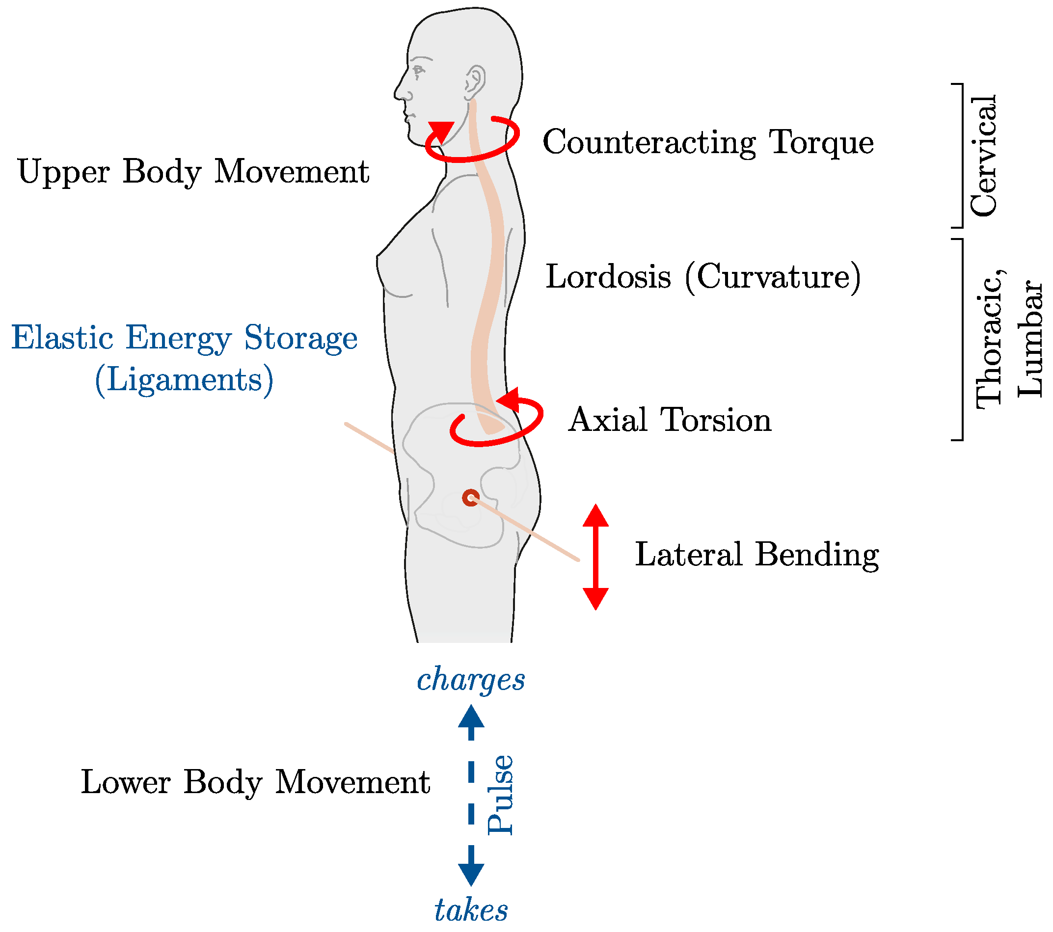
Kakehashi et al. [
16] presented a lightweight spine mechanism for humanoid robots that mimics the musculoskeletal structure of the cervical vertebra, the thoracic vertebra, and the lumbar vertebra by using a tendon-driven continuum joint. Here, a first step is taken to reproduce the versatile freedom of movement of the spine in a robotic system. The freedom of spinal motion is paramount, according to [
17], and they claim that this is a fundamental component of efficient human locomotion. A visual understanding of the coupled spinal motion can be seen in the
Figure 2. The investigation of the origin of the rotation of the pelvis (along the longitudinal axis) has led to the observation that the pelvis is not driven by an induced torque of the legs [
17]. Prima fascie, no counter-acting torque of the legs to the ground has been observed, and thus, this can only be explained by a driving torque of the spine. The latter is explained by the lordotic (curved) spine, which translates a primitive lateral bend into an axial torque, and thus, driving the pelvis.
Building on the functional use of passive compliance for the design of a robotic spine in [
13] and related control approaches for an underactuated, tendon-driven continuum joint [
7,
18], this paper aims to explore the resonance behavior of a tendon-driven continuum joint for periodic natural motions. Related works in this direction exploit periodic natural motion for stiffness parameter identification [
19] or stable open loop control [
20] a for two-segment soft robotic arm. While both works uses isolated bending directions for their oscillatory motions, the current manuscript excites torsional oscillations only. The contributions of this work are as follows:
This paper is divided into five sections. In
Section 2, the mathematical model is outlined. Then,
Section 3 follows the description of the experimental setup and materials used. The performed experiments and their results are shown in
Section 4. In the final discussion,
Section 5, these results are summarized and future experiments are discussed.
Figure 2.
Illustration of the impulse-loaded spine and coupled motion postulated by the spinal engine theory. The outline of the human was taken from [
21]. Pelvic rotation, the curvature of the spine, leads to shoulder rotation and vice versa.
Figure 2.
Illustration of the impulse-loaded spine and coupled motion postulated by the spinal engine theory. The outline of the human was taken from [
21]. Pelvic rotation, the curvature of the spine, leads to shoulder rotation and vice versa.
2. Torsional Harmonic Oscillator Model
The motion of continuum joints involve a structural deformation. To accurately describe this deformation, rigorous modeling approaches are required. In the past, different types of application cases for continuum joints and robots have produced a large amount of different modeling techniques to describe their deformation and the overall motion mathematically. The recent work of [
22] classified the available models into four categories, Continuum mechanics models, Geometric models, Discrete material models, and Surrogate models.
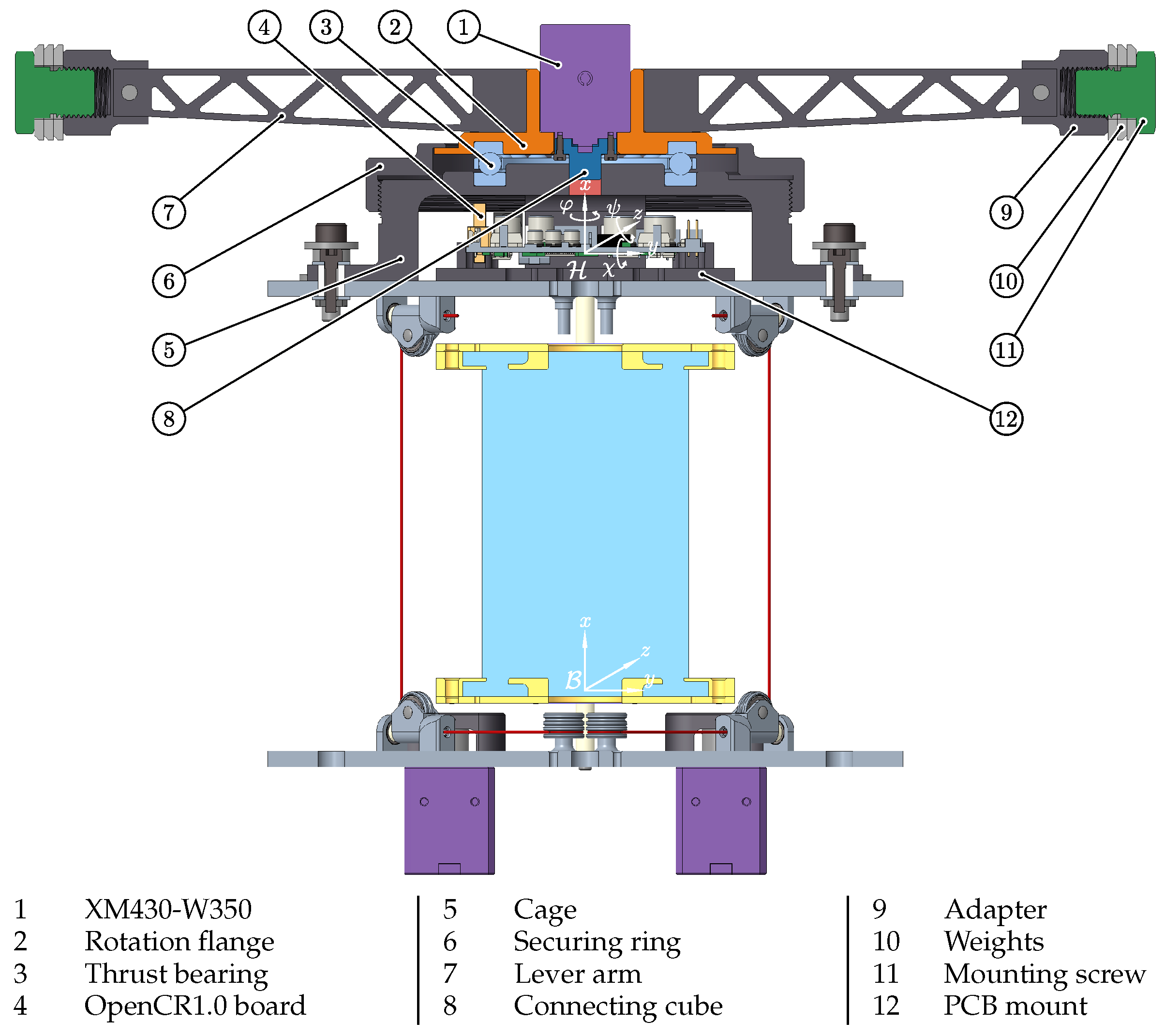
The aim of the present paper is the experimental characterization of the resonance behavior of the continuum joint depicted in
Figure 3 while torsionally excited. This characterization will be done purely on experimental data by the frequency dependent relation of input
and output
. Secondly, the damping behavior of the free torsional oscillator shall be characterized using a linear second order mechanical system. Similar to the work from [
23], the continuum joint mechanism is thereby approximated as a mass less linear spring, the continuum, with a rigid body on the top end while the bottom end is clamped to the ground. This model approach belongs to third category discrete material models defined by [
22].
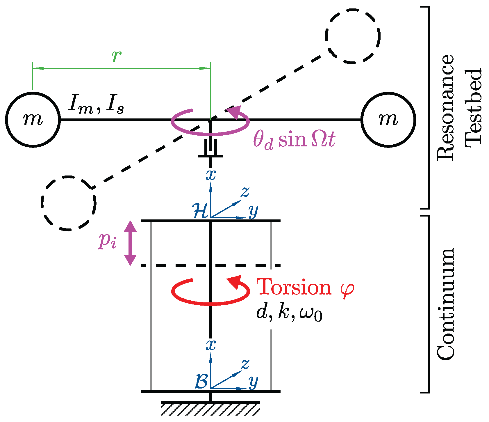
The resulting differential equation to describe the experimentally observed damping behavior is approximated as a free torsional oscillator with constant coefficients
, and
k for the resulting torsional angle
at the tip of the continuum (rotation along the
-axis, see
Figure 3):
Figure 3.
Sectional view of the test bed.
Figure 3.
Sectional view of the test bed.
Whereby in Equation (2) the following substitutions have been made:
to gain a generalized formulation. The inertia
I along the rotation axis due to the structure and additional weights
employed is:
where
r is the radial distance of the additional weights and
is the inertia of the structure, which is calculated by
Creo. The damping parameter
d in
is used to capture the viscous damping properties of the silicone material and the friction in the tendon kinematics. The stiffness parameter
k in
captures the torsional stiffness of the continuum, which can be computed straightforwardly from the shear modulus
G of the material, the second moment of area
J of the continuum cross section, and the length
L of the continuum joint:
The parameters above are taken from a similar continuum joint setup in [
24].
As depicted in
Figure 4, the driving oscillation
relative to the
frame is induced by an oscillating pendulum motion on the top of the continuum, i.e., the resonance testbed. In addition, the tendons attached to the bottom
and head
plates allow for a change in the compression state of the continuum by varying simultaneously the length of the tendons which results in a compression
of the continuum.
3. Experimental Setup
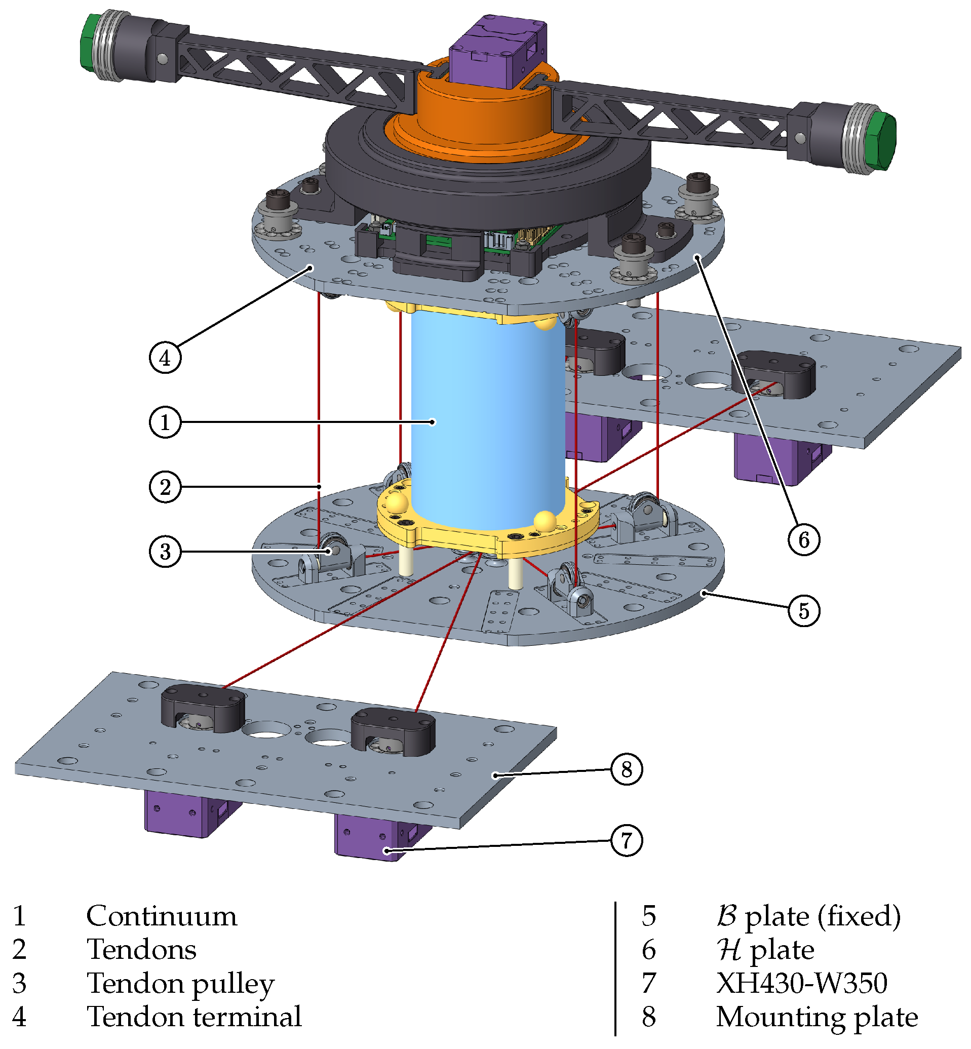
The setup shown in
Figure 1 is used as a test bed. For the cylindrically continuum material, we use a two component silicone from [
25] see
Table 1, which is casted around the connectors for the top and bottom adapter plates; for further details on the construction process we refer to [
18]. Four Dynamixel XH430-W350 motors are used in a symmetrical arrangement to ensure a uniform pretension of the continuum element. The tendons are guided under the center of the silicone and then directed to the respective outer pulley units by idler rollers. This pulley unit is also present in the upper assembly, whereby the steal tendon is then fixed with a terminal. The latter leads to our assumption for neglecting the influence of the tendon elasticities, see also
Section 5.2.
The forced oscillation is induced by another Dynamixel XM430-W350 by allowing it to rotate relative to the upper plate, supported by a thrust bearing. This rotation causes the lever arm and the weights attached to it to rotate. The rotation is captured by the integrated MPU9250 gyroscope/accelerometer of the ROBOTIS OpenCR1.0 board, whereby the filter of [
26] is used to minimize the drift of the gyroscope. The time response of the filtered orientation angles
of the
plate relative to the
plate is used for further analysis, see
Figure 3.
In order to be able to guarantee a consistent initial condition, it is necessary to apply a defined pretension to the tendons at the beginning of each test series. This is achieved using a current-controlled routine that applies a pretension to the tendons up to a defined motor current value. Afterwards, the initial motor positions are stored and a final motor position is determined by means of a linearized matrix mapping and the desired pretension position. This final motor position is controlled by a proportional-integral position controller based on the actual pose and the target pose so that the top plate is parallel to that of the
y-
z plane in the
-frame, see
Figure 3. The effects of different pretensioning control methods provided by the used Dynamixels, i.e., position-controlled with and without motor current limit, solely current-controlled, can be found in the
Supplementary Material S1.
4. Experiments
In this section, the variable resonant behavior of the continuum joint used is shown by an experimental setup. This corresponds to the main contribution of the present publication, see contribution 1. Furthermore, the damping behavior is investigated, which should provide further information with respect to a possible future modeling.
4.1. Resonance
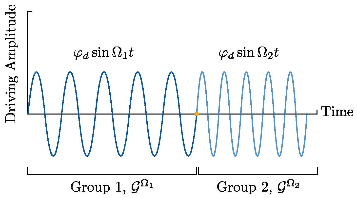
The resonance behavior is determined by applying a frequency-discretized driving oscillation
of constant amplitude
, see
Figure 5.
Each group
consists of five periods (this number was empirically chosen), each taken after a transient delay time of
, of the same frequency
, causing the system to reach a steady state oscillation. The mean value (
represents the averaging operator) of the measured forced amplitudes
over one group
corresponds to the measured forced amplitude of this driving frequency group. Finally, this value is normalised by the amplitude of the driving oscillation
, which leads to the following amplitude response [
27]:
which is used in the following figures.
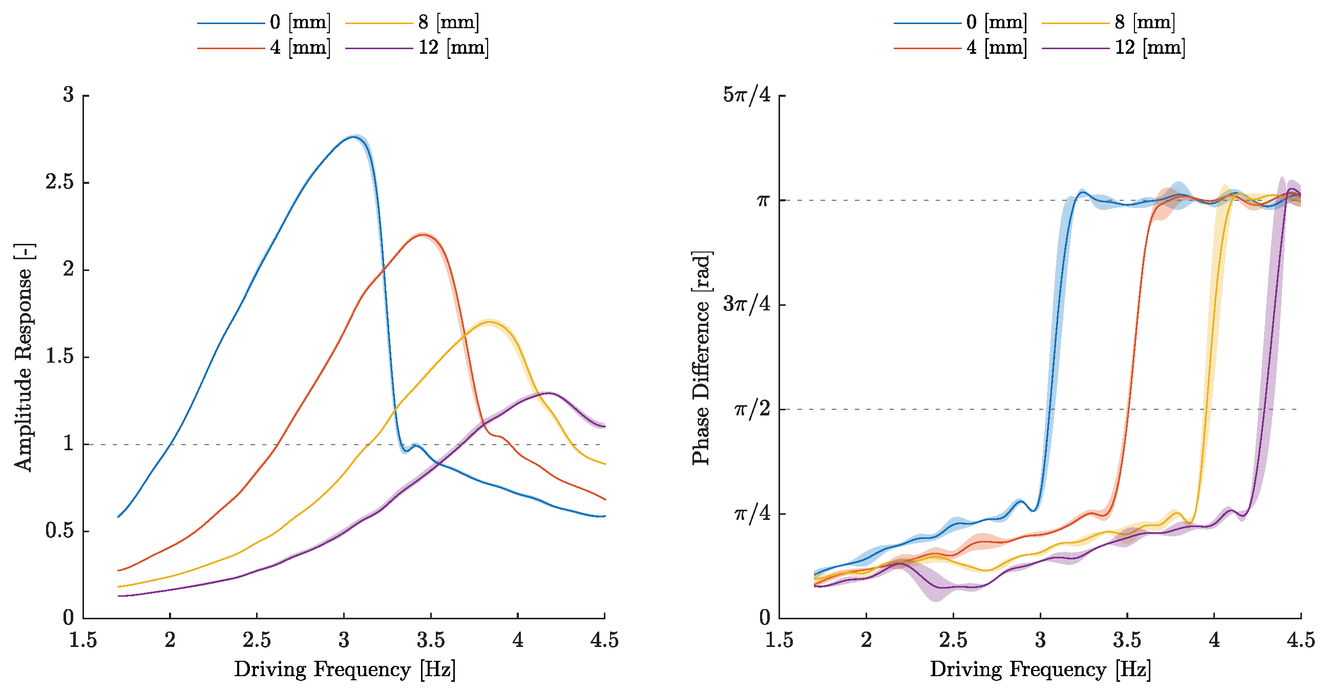
The amplitude response for different pretensions, i.e., the uniform change in length of the tendons, over the frequency (the amplitude response over time can be found in
Supplementary Video S1) is plotted in the left graph of
Figure 6. The tube shown surrounding each solid average line represents one standard deviation, where
measurements were taken for each pretension. In this, the effect can be observed that as the pretension increases, the resonance frequency
shifts to higher frequencies and the resulting amplitude response
decreases. For a system behaving like a harmonic oscillator with constant natural angular frequency
, a shift of its resonance maximum to smaller frequencies with decreasing amplitude should be observed as Lehr’s damping factor
D increases [
27]. This discrepancy will be discussed in the next section and possible explanations will be given.
The phase difference analysis, which characterises the resonance from another point of view, is shown in the right graph of
Figure 6. The resonant behavior arises from the phase shift of
, since the resulting velocity
is in phase with the external driving force, and thus, the system permanently receives power. This power increase is only limited by the dissipative friction. An alternative approach is to use the Lissajous curves, see
Figure 7, in which the phase shift can be shown in a qualitative way.
A certain shape corresponds to a certain phase shift. The advantage here is that no numerical difference has to be computed in order to obtain a time difference, from which the phase shift can be calculated. For an amplitude ratio of 1:1, an ascending line from the lower left to the upper right corresponds to a phase shift , an evolving ellipse along the former line, forms a circle and then an ellipse again towards a line but rotated to the left undergoes the phase shifts . Technical limits become apparent here, as the driving amplitude does not provide the nominal amplitude at high frequencies. Presumably, this would allow for a wider resonance range with a higher amplitude response.
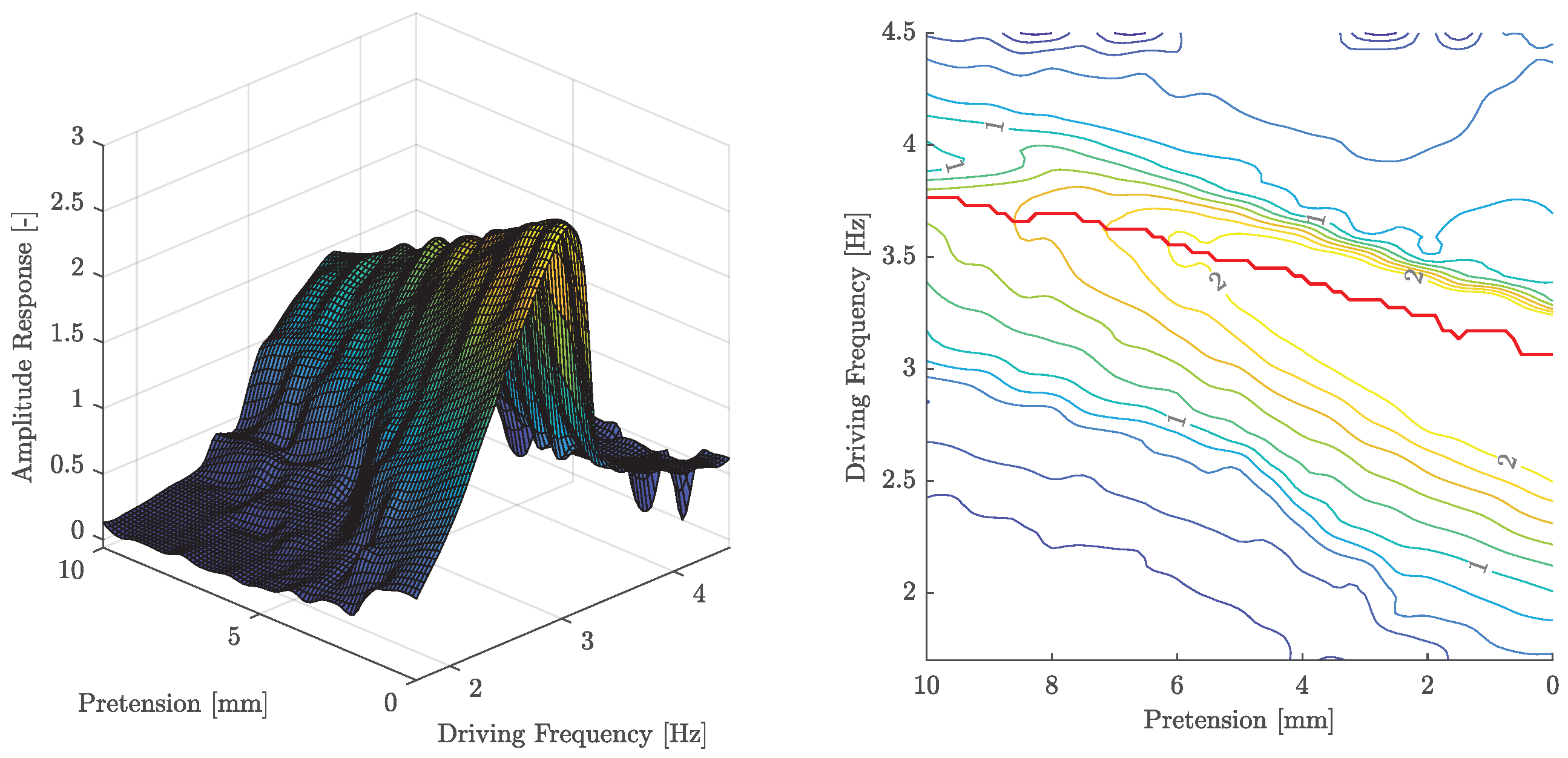
A generalised experiment on the sensitivity of the continuum’s compression state is depicted in
Figure 8. Here, the amplitude response changes over a continuous interval of tendon lengths by iteratively adjusting the length of the four tendons
simultaneously.
The point of resonance shifts to higher frequencies and the forced amplitude becomes smaller with increased pretension. An additional effect occurs after reaching a certain threshold of the pretension. Here, the normalized amplitude remains bounded to a value of one. This can be understood as a type of saturation and thus defines a usable range in which the resonant behavior of the continuum can be used. However, it cannot be ruled out that unknown disturbance effects, i.e., insufficient driving frequency or force, are the actual cause, so that further tests are necessary.
4.2. Damping
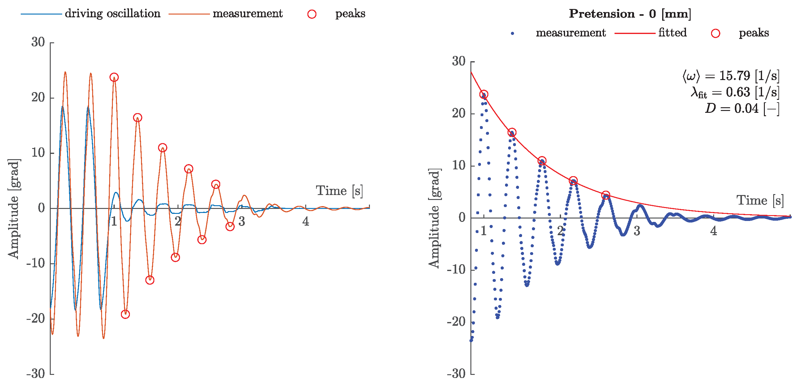
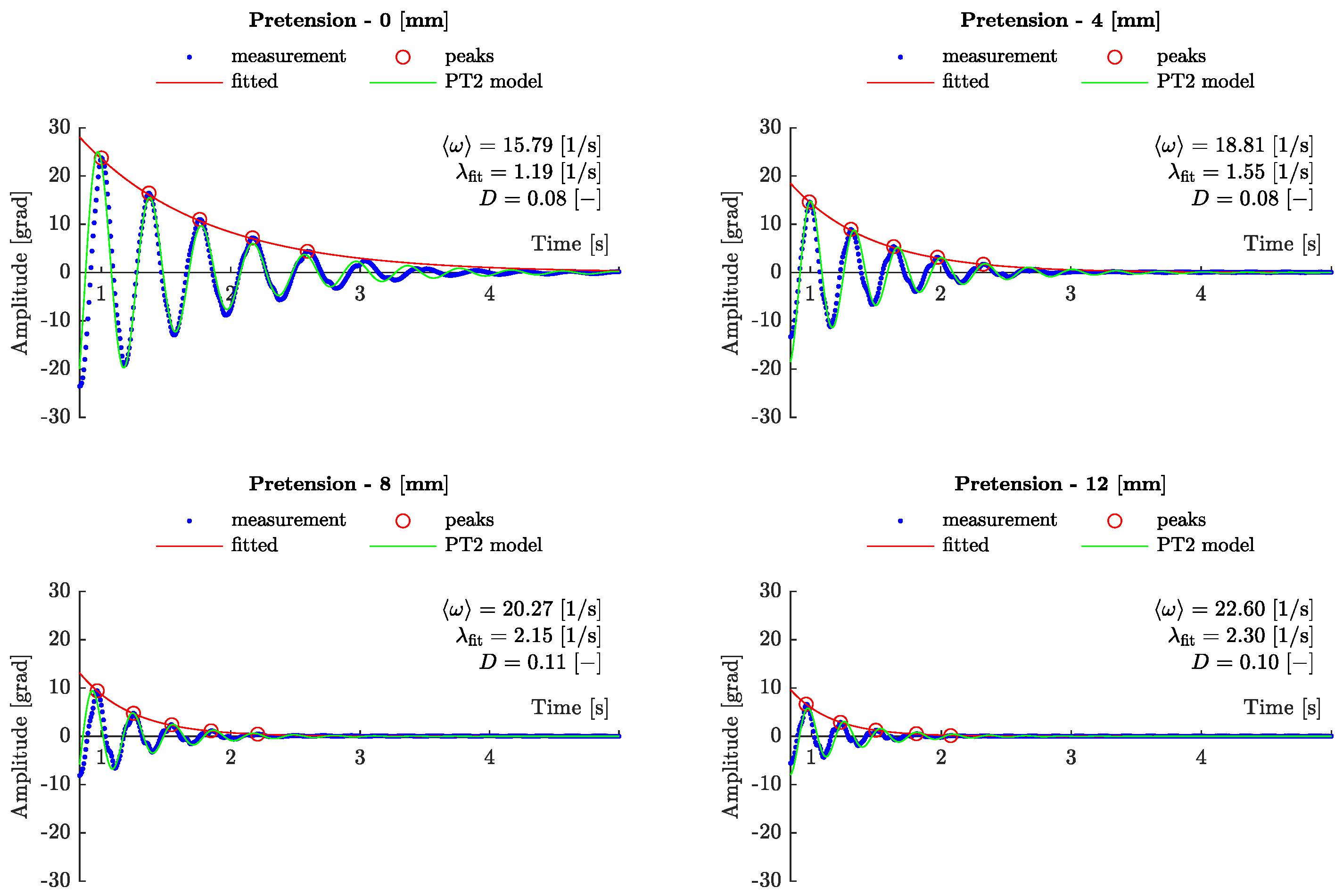
In this section, the damping property of the overall system is analyzed, which becomes relevant for modeling. For this purpose, the continuum is deflected to such an extent that the steady-state amplitude response is already greater than one. After reaching the steady-state oscillation, the driving oscillation is stopped at the zero position of the deflection and the free oscillation of the continuum is recorded. This procedure can be seen in the left graph of
Figure 9. A parasitic effect, which can be seen in the small oscillation of the stopped driven oscillation, can also be observed in the left graph. However, this is not believed to have a significant effect on the following results.
Upon this decaying oscillation, the positive and negative peaks are detected and the enveloping exponential decay curve
is derived by utilizing a non-linear least squares method [
28], see the right graph of
Figure 9. From this, the decay coefficient
is used with the averaged angular frequency
to obtain the Lehr’s damping of the system:
The reciprocal value of this attenuation is proportional to the quality factor
Q of the system:
which can be used as a central quantity to describe the energy loss of the oscillatory system [
27]. Knowing the total inertia
I, which has already been specified in
Section 2, the model-specific quantities
from Equation (2) can be determined as follows:
In
Figure 10, the measured damping behavior is shown over different pretensions while a comparison is given with the prediction of the linear second-order model, see Equation (2). With increasing pretension of the tendons, an increase in the decay coefficient
can be observed. This is accompanied by a simultaneously increasing mean angular frequency
. The quotient of these quantities, Lehr’s damping
D, remains approximately constant over the studied range. Therefore, the damping of the system
d is less sensitive towards a change of the compression state
of the continuum. At the same time, this means that the quality factor
Q, and thus, the resonance sharpness is morphologically similar. This finding merits further investigation.
5. Summary and Future Work
These observations indicate that the overall system, consisting of a cylindrical continuum material and a tendon actuation, has a variable resonant frequency range that can be modified by a suitable geometric structure, the choice of material and, in particular, by pre-tensioning. The stiffness of the continuum is linear [
24] in the range used, and therefore, cannot be the cause of this behavior. Instead, the combination with a tendon actuation creates a non-linear overall dynamics that allows the natural angular frequency
and the decay coefficient of the overall system, and thus, the onset of resonance, to be varied. The observation that Lehr’s damping measure remains nearly constant, confirming the similarity in principle with respect to the energy dissipation of the respective resonant modes, requires further analysis.
5.1. Real-World Applications
One real-world application which can make use of the functional observation described above lies in the actuation of a robotic torso. Articulated spine mechanisms using metal springs can be found in the works of [
29,
30]. Here, an additonal mechanism is used to alter the torsional stiffness of the robotic upper body. In contrast, the continuum joint design investigated in the work would combine the motion capabilities and the variation of the torsional stiffness in one element.
The joint limits for a human torso can be found by the total mobility, see also
Figure 11, of the thoracic and lumbar spine around the trochanter major (
•). This can then be deduced to the following technical terms:
Given the results of
Section 4.1, where we observed an amplitude response of up to three with a given forced amplitude
, we fulfill the desired yaw range of motion of a human torso. By combining the resonant behavior of such a joint, it is planed to have a energy-efficient rotation during locomotion along the yaw axis of a robotic torso. Additionally, the parallel stiffness induced by the continuum joint allows for weight compensation or modulating the required joint torques for pitch and roll movements. Via morphological design alternations, a curved structure can lead to motion couplings, which reassembles the spinal engine described above.
5.2. Limitations
In the following subsections, five types of limitations of the experimental investigation presented in this paper will be discussed.
5.2.1. Tendon Elasticities
The effect of the tendon elasticities is assumed to be negligible. This follows the argumentation, that for the parallel arrangement of the tendons, their spring constants sum up. Furthermore, steel tendons (CarlStahl TechnoCables, DE-73079, Süßen, Germany. Article number: SE000105) are used, which have a comparable higher tensile strength of . Combining this with the underactuated system, the authors believe that the elasticities are predominately given by the continuum material. However, the kinematic constraints of the tendons during the torsional movement, which may lead to a asymmetric stress state over the periodic motion, needs further investigation and a clear understanding for a consecutive modeling.
5.2.2. Transferability
The experiments investigates the behavior of a single joint type with a circular cross-section, limiting the exploration of other cross-sectional shapes. Additionally, specific lengths of mechanisms were not investigated, affecting stiffness and eigenfrequency. Future research will address these limitations by analyzing the transferability of findings to other joint types and exploring the effects of different cross-sections and lengths on mechanical properties. This discussion highlights avenues for further investigation in subsequent experiments, as outlined in the outlook section.
Furthermore, the experimental investigation of the torsional oscillations and their resonance behavior presented in this work is limited to a straight continuum joint configuration. Torsional oscillations with a bent continuum are not investigated. Clearly, the deformation state of the continuum will be asymmetric for large bending angles, yielding potentially coupled oscillation with the same excitation, which potentially influences the found resonance behavior. Furthermore, the resonance behavior with respect to a bending excitation is not investigated, as was performed in, e.g., [
19] for stiffness identification or [
20] for open loop control.
5.2.3. Anharmonicity
When looking at the amplitude response over different pretensions, the effect could be observed that the point of resonance shifts to higher frequencies, not to the left as expected for a harmonic oscillator with increasing Lehr’s damping
D. This behavior may be due to anharmonicity, i.e., the deviation of a system from being a harmonic oscillator [
27]. This can usually be observed by an asymmetry in the phase space, i.e., squeezing of the trajectory of position over velocity/impulse. This is usually explained by a non-linear, anharmonic force law [
27]. For the corresponding phase space analysis, please refer to
Supplementary Video S1.
5.2.4. Actuation Saturation
Above a certain pretension , an onset of saturation of the amplitude response can be observed. It is unclear whether this is due to the lack of excitation capability or whether there is a limit to the continuum with respect to the change in stiffness. However, such a limit can be specified as a parameter to restrict the usable range.
5.2.5. Observational Error
Another possible source of error that should be considered is whether there are obliterating dynamic effects so that the excitation applied to the lever arm does not actually occur in the overall system. Such a deviation could lead to a systematic error in the determination of the damping quantities, as the synchronization of the time instants of the respective signals is significant here. To date, only a decreasing driving amplitude with increasing frequency could be observed, which, however, does not negate the principal resonant behavior.
5.3. Future Work
In future experiments, one analysis that may lead to a quantitative statement about the benefits of resonant operation is the following. With increasing frequency of the constant driving amplitude, a linear increase in the necessary driving motor current should be observed. Therefore, the evaluation of the motor current in the resonant state of the overall system should show a reduced current consumption. The ratio of the linear increase to this reduction could serve as a measure of the energy saved.
In another experiment, this effect will be further investigated for different poses of the continuum joint. In addition, the influence of different shapes of the continuum material will be explored. This should serve as a demonstrator for motion couplings similar to those described by the spinal engine theory.
Future research will focus on developing a more generalized frequency response transfer function to predict the varying resonance behavior of the joint, encompassing variations in cross-sectional shapes and lengths to provide a comprehensive understanding of its mechanical behavior across different configurations. In addition to the aforementioned goals, it is important to note that while the current work focused on experimental understanding, future endeavors will incorporate a model-based approach to further refine the frequency response transfer function for the joint, enhancing its predictive capabilities and applicability across diverse scenarios.


