Article

Optimizing Assembly in Wiring Boxes Using API Technology for Digital Twin

by
Carmen-Cristiana Cazacu
*,
Ioana Iorga
,
Radu Constantin Parpală
,
Cicerone Laurențiu Popa
and
Costel Emil Coteț
Robots and Production Systems Department, The Faculty of Industrial Engineering and Robotics, National University of Science and Technology POLITEHNICA Bucharest, Splaiul Independenței 313, 060041 Bucharest, Romania
*
Author to whom correspondence should be addressed.
Appl. Sci. 2024, 14(20), 9483; https://doi.org/10.3390/app14209483
Submission received: 21 August 2024 / Revised: 11 October 2024 / Accepted: 14 October 2024 / Published: 17 October 2024

Abstract

:
This study explores the automation enhancement in the assembly process of wiring harnesses for automotive applications, focusing on manually inserting fuses and relays into boxes—a task known for quality and efficiency challenges. This research aimed to address these challenges by implementing a robotic arm integrated with API technology for digital twin. The methods used included the development of a digital twin model to simulate and monitor the assembly process, supported by real-time adjustments and optimizations. The results showed that the robotic system significantly improved the accuracy and speed of fuse insertion, reducing the insertion errors typically seen in manual operations. The conclusions drawn from the research confirm the feasibility of using robotic automation supported by digital twin technology to enhance assembly processes in automotive manufacturing, promising substantial improvements in production efficiency and quality control.

1. Introduction

Currently, the production of automotive wiring harnesses is still quite dependent on human resources, with the assembly of the harnesses largely done through manual operations. Increasing productivity is primarily achieved through efficient workload distribution among workstations, ensuring ergonomic workstations, and streamlining the component feeding process for the assembly line.
The continuous evolution of the security and multimedia systems integrated into vehicles poses a challenge for wiring harness manufacturers. They must provide the automotive industry with complex wiring harnesses with a lean architecture that can be easily integrated within the vehicle’s architecture. Components such as terminals, connectors, and connector seals are becoming smaller, making manual handling increasingly difficult. Other components, like fuse boxes and relays, are evolving technically, with manufacturers providing new technological solutions to enhance the flexibility of the wiring harness, such as introducing integrated circuit boards into fuse boxes and relays.
However, even as these components evolve, a part of the process remains constant in current practice, specifically the manual insertion of fuses and relays into the box. Therefore, this research aims to increase the level of automation in the assembly process by offering an automation solution that can be easily implemented by manufacturers.
The studied solution consists of using a robotic arm for the insertion of fuses and re-lays, considering the technical constraints related to insertion, force, and angle, which are difficult to control in manual operations. This study aims to provide solutions to eliminate the quality issues caused by factors that are challenging for an operator to control, such as angled insertion (that leads to an imperfect contact between the fuse and terminal), incomplete insertion (difficult to detect, caused by insufficient force applied during the fuse insertion operation), fuse/terminal damage due to excessive force application, and fuse insertion into the wrong cavity (leading to an operational time increase due to the need for rework).
To appeal to wiring harness manufacturers, the automation solution needs to be flexible, be easily adaptable to changes in the fuse and relay box configuration, consider the cost factors for investment and implementation, and have compact dimensions to avoid the major reconfiguration of the assembly line. Additionally, it should aim to facilitate the professional reconversion of the operator (e.g., training in robotic arm operation). The main goal of increasing automation is to minimize quality risks by increasing the efficiency of the process, not to reduce the workforce.

2. The State of the Art

Research in the field of wiring harness automation has gained momentum in recent years, becoming a subject of increasing interest due to the growing significance of wiring harnesses in vehicles and the substantial role that manual operations play in the production process. Automation can be integrated in all the phases of wiring production: the design, the wiring harness assembly, the logistical processes of storing components and feeding the assembly line, etc.
The automation of wire harness design, manufacturing, and assembly is a key focus in the automotive industry, with the potential for significant time and cost savings [1]. The paper “On Automation Along the Automotive Wire Harness Value Chain” describes a project that aimed to automate the design and generation of wire harnesses for vehicles, with the goal of reducing design time and cost by at least 50% by using graph-based design languages and the VEC (vehicle electrical container) as an open data standard. The required data and process steps for generating the wire harness, as well as a wire harness assembly simulation, were also described [1].
While the highly customized nature of wire harnesses presents a challenge, the development of a robotic manipulator with sensorized fingers offers a promising step towards automated manufacturing [2]. The paper, [2], proposes a robotic system that can be easily adapted to produce different types of wire harnesses and cable assemblies. The system consists of a robotic arm, a gripper, and sensor-equipped fingers that are capable of executing wire harness manipulation tasks. The system can be easily adapted to produce different products by updating the order of operations, trajectories, and dimensions/positioning of low-cost mechanical parts. However, due to the variety of wiring harnesses produced, realizing an automatic machine for a specific wire harness is not affordable, and manual production remains still the most cost-effective solution [2].
The need for increased automation in the assembly flow is also highlighted, with the potential benefits including increased productivity and a reduced fabrication time. The paper “Research regarding assembly flow optimization of wiring harness in automotive industry” discusses the challenges of wiring harness production in the automotive industry and presents a case study to identify the main factor affecting the productivity of a dynamic assembly line for wiring harness production, with the goal of optimizing the wiring assembly flow by partially automating the production process. The limitations underscored in the paper were confirmed by many works that followed. The high variety of vehicle options and the modifications that can be made during their development make full automation challenging, no matter the approach. There are still many manual operations for which automated technical solutions do not yet exist. Many constraints must be considered before investing in increased automation, including a production process overview and maintaining competitiveness [3].
Finally, in the paper “Automatization of the Cable-Routing-Process within the Automated Production of Wiring Systems”, the successful automation of the cable-routing process within the production of wiring systems is demonstrated, using collaborative robots and 3D-printed prototypes. The researchers developed an automated system using collaborative robots and 3D-printed cable grippers to automate the cable routing process in the production of wiring systems for vehicles. The automated routing concept was tested in a prototypical production cell, and the strengths and weaknesses of the system were analyzed, with possible solutions proposed [4].
The manual taping process is one of the most elaborate processes of wire harness manufacturing. The paper “Innovative Solutions for the Covering Process in the Manufacturing of Wire Harnesses to Increase the Automation Degree” summarizes a study on alternative processes to replace the manual taping process in wire harness manufacturing, to increase the degree of automation. The study explored alternative processes to replace the manual taping process in wire harness manufacturing, which accounts for over 30% of production time and represents the highest need for automation. The study involved the conception and validation of two prototypical test setups for different coating processes as alternatives to the manual taping process [5].
Research has been conducted to increase the level of automation in the wiring harness electrical testing process. In the paper “Automation of Electrical Cable Harnesses Testing” is described the development of a modular automated system for testing cable harnesses that outperform manual testing in terms of productivity, reliability, safety, and cost-effectiveness. To improve the system’s adaptability, the modularization method was applied to optimize the design of individual modules and to reduce the interdependency between the modules in case of punctual upgrades. The case study conducted during this research revealed that the automated testing system outperformed manual testing in terms of cost-saving, productivity, and reliability, but further research is needed to make the system more adaptable to changing requirements [6].
The use of collaborative robots in the wire harness assembly process is a promising solution to improve productivity and worker ergonomics [7,8]. The paper “Specifying task allocation in automotive wire harness assembly stations for Human-Robot Collaboration” presents a design methodology for human-centered manufacturing systems, focusing on task allocation and collaboration levels. The proposed methodology combines a hierarchical task analysis with assessments of the cognitive and physical levels of automation, the levels of human–robot collaboration, and the levels of operator skill requirements to identify possible combinations for automation and collaboration solutions. The methodology is intended to support system designers and integrators in identifying the potential and the extent of human–robot collaboration in collaborative manufacturing assembly operations [7]. The papers “Wire Harness Assembly Process Supported by Collaborative Robots: Literature Review and Call for R&D” and “Wire Harness Assembly Process Supported by a Collaborative Robot: A Case Study Focus on Ergonomics”, further explore the potential of collaborative robots in this process, highlighting the need for further research in areas such as cost–benefit analyses and cycle times. Introducing a collaborative robot (cobot) into the process of arranging cable ties in wire harness assembly brings about a notable decrease in the ergonomic hazards faced by workers, as evidenced by the RULA and JSI scores. By handling the most repetitive and awkward positions, the cobot minimizes the amount of non-ergonomic responsibilities for the human operator. Additionally, the integration of a computer vision system with the cobot ensures that this collaborative approach is extremely flexible and can easily adjust to various wire harness categories and production batches [8].
Román-Ibáñez et al. provide a specific application of collaborative robotics in the spot-taping process, demonstrating its potential to reduce processing time and improve worker conditions. The proposed method involves adding robotic arms to collaborate with human workers in the wire harness spot-taping process, with the robotic arms performing the spot taping while the human worker positions the cable. The proposed solution is expected to have a positive impact on companies producing wire harnesses and improve the ergonomic conditions of workers by removing the most tedious and repetitive tasks [9].
As previously shown in this paper, automation research reaches many aspects of wiring harness production; however, there is at least one domain that could benefit from increasing the automation degree, and for which, there is not sufficient information available from prior research. The subject was approached solely at a conceptual level, lacking practical implementation or specific data to further advance research in the field of automated fuse insertion.
The insertion of fuses and relays inside the fuses and relays boxes remains, in current practice, an operation that is done manually. Since fuses and relays are sensitives components, the insertion operation must be done with extreme care, respecting technical parameters like the insertion angle and the insertion force. The main concern regarding bad fuse insertion is that the defect is hard to identify during harness electrical testing, so having a correct fuse/relay insertion operation plays a crucial role in reaching a good quality level for the wiring harness and for the vehicle. Defects caused by incorrect insertion can lead to quality issues that can affect the OEM plants by disrupting the normal workflow, resulting in a necessity to carry out a repair on the vehicle, or even resulting in the final customer needing to go to a service unit due to a function loss.
This study aims to find a solution to increase the automation degree by using a robotic arm to insert the fuses and relays, while respecting the technical requirements of all the elements involved in the operation (the technical parameters of fuses and relays, correlated with the cavities geometry of the box). The chosen approach is to optimize the insertion operations by API technology for digital twin.
Both Thelen et al. and Garg et al. have explored the applications of digital twin technology in different domains. Thelen’s work focuses on the role of uncertainty quantification and optimization in digital twins, with a specific case study on a battery digital twin. Garg, on the other hand, presents a digital twin model for FANUC robots, which enables online/remote programming and simulation using virtual reality. Both studies highlight the potential of digital twin technology in improving process design, quality control, and decision making in various industries [10,11,12].
The paper “A Survey on Digital Twin: Definitions, Characteristics, Applications, and Design Implications” provides a comprehensive survey on the concept of digital twins (DTs), exploring their definitions, characteristics, applications, and design implications. It highlights the evolution of DTs from the basic mirrored systems used by NASA to the advanced AI-driven models integrated with the IoT and big data analytics. The study categorizes DT applications across various domains, including manufacturing, aviation, and healthcare, emphasizing their potential to enhance predictive maintenance, optimize processes, and enable personalized medicine. The authors also discuss the socio-technical and collaborative design approaches necessary for effective DT implementation and propose lifecycle models for developing and deploying DTs [13].
In research on the application of digital twin technology to the mounting of resistors in cable boxes, several recent articles were studied, offering important insights into the evolution and applicability of this concept. Beginning with the study of the virtual training center for industrial robotic arms, the potential of the digital twin to improve training in automated production, including the assembly of electronic components, was demonstrated [14]. To optimize production processes in accordance with environmental regulations, it is necessary to integrate sustainability functions into the digital twin using methods such as a multi-criteria analysis [15]. As the digital twin concept evolves, the integration of artificial intelligence and machine learning is being explored to optimize manufacturing processes and predictive maintenance, which could be relevant for fuse assembly in intelligent production environments [16]. These studies highlight the importance of digitization and automation within Industry 4.0, emphasizing their positive impact on the efficiency and sustainability of production processes.
This paper builds on existing research in automation within wiring harness production, with a particular focus on the challenges associated with the manual insertion of fuses and relays. While previous studies have explored various aspects of automation, such as robotic manipulators and collaborative robots for wiring assembly, the specific task of fuse insertion has remained predominantly manual due to the precision and care required in handling sensitive components. In this work, we propose an innovative solution, utilizing a robotic arm integrated with API technology for digital twin to optimize the assembly process in automotive fuse boxes. Integrating a digital twin model enables real-time monitoring, simulation, and adjustments, enhancing the accuracy and efficiency of the insertion process. Our results demonstrate that the system can significantly reduce manual errors and improve the overall production quality, providing a viable solution for increasing automation in this critical aspect of automotive manufacturing.

3. Overview of the System Architecture

3.1. Technical Specification for Ufactory Lite 6 Robot

The hardware parameters, characteristics, and joints for a Ufactory Lite 6 robot are presented in Table 1 [17].
In Figure 1 is a technical representation of the robotic arm, and the total height of the robotic arm is 683.5 mm, the total length of the arm in a fully extended position is 440 mm, and there is a segment of the arm that has a length of 61.5 mm. The orange circle indicates the working area or the range of motion of the arm. These details are useful for understanding the dimensions and the space occupied by the robotic arm in its operating environment.

3.2. Kinematics of Robotic Arm

3.2.1. Denavit–Hartenberg Parameters for Lite 6

Based on the parameters provided for the Lite 6 robotic arm, Table 2 and Table 3 [18], we adjust the kinematic and dynamic parameters accordingly. Here are the updated parameters for the Lite 6.
The key kinematic parameters of the robotic arm, such as link lengths and joint angles, were carefully adjusted to ensure optimal performance. These adjustments enabled the robotic system to achieve the precision required for fuse insertion while maintaining flexibility in handling different configurations.
The kinematics of the robotic arm were defined using Denavit–Hartenberg parameters to control its movements with high precision. This modeling enabled accurate manipulation in three-dimensional space, ensuring precise insertion angles and positions.

3.2.2. Homogeneous and Combined Transformation Matrices

From each joint i, the transformation matrix Ti is given by:
Standard DH Transformation Matrices
T i s t a n d a r d = c o s ( θ i ) s i n ( θ i ) c o s ( α i )   s i n ( θ i ) s i n ( α i )   a i c o s ( θ i ) s i n ( θ i ) c o s ( θ i ) c o s ( α i )   c o s ( θ i ) c o s ( α i )   a i s i n ( θ i ) 0 s i n ( α i )   c o s ( α i )   d i 0 0 0 1
Modified DH Transformation Matrices
T i m o d i f i e d = c o s ( θ i ) s i n ( θ i )   0 a i s i n ( θ i ) c o s ( α i ) c o s ( θ i ) c o s ( α i )   s i n ( α i )   d i s i n ( α i ) s i n ( θ i ) s i n ( α i ) c o s ( θ i ) s i n ( α i )   c o s ( α i )   d i c o s ( α i ) 0 0 0 1
Combined transformation matrices for both the standard and modified DH parameters, providing a comprehensive description of the end-effector’s position and orientation in the Ufactory Lite 6 robot arm.
Using the modified Denavit–Hartenberg (DH) parameters specific to the Lite 6, we built the transformation matrices for each joint [19].
J o i n t   1 :   T 1 = c o s ( θ 1 ) s i n ( θ 1 ) 0   0 s i n ( θ 1 ) c o s ( θ 1 ) 0 0 0 0 1 243.3 0 0 0 1 = 1 0 0   0 0 1 0 0 0 0 1 243.3 0 0 0 1
J o i n t   2 :   T 2 = c o s ( θ 2 ) s i n ( θ 2 ) 0   0 0 0 1 0 s i n ( θ 2 ) c o s ( θ 2 ) 0 0 0 0 0 1 = 0 1 0   0 0 0 1 0 1 0 0 0 0 0 0 1
J o i n t   3 :   T 3 = c o s ( θ 3 ) s i n ( θ 3 ) 0   200 0 0 1 0 s i n ( θ 3 ) c o s ( θ 3 ) 0 0 0 0 0 1 = 0 1 0   200 0 0 1 0 1 0 0 0 0 0 0 1
J o i n t   4 :   T 4 = c o s ( θ 4 ) s i n ( θ 4 ) 0   87 0 0 1 227.6 s i n ( θ 4 ) c o s ( θ 4 ) 0 0 0 0 0 1 = 1 0 0   87 0 0 1 227.6 0 1 0 0 0 0 0 1
J o i n t   5 :   T 5 = c o s ( θ 5 ) s i n ( θ 5 ) 0   0 0 0 1 0 s i n ( θ 5 ) c o s ( θ 5 ) 0 0 0 0 0 1 = 1 0 0   0 0 0 1 0 0 1 0 0 0 0 0 1
J o i n t   6 :   T 6 = c o s ( θ 6 ) s i n ( θ 6 ) 0   0 0 0 1 61.5 s i n ( θ 6 ) c o s ( θ 6 ) 0 0 0 0 0 1 = 1 0 0   0 0 0 1 61.5 0 1 0 0 0 0 0 1
The overall transformation matrix from the base to the end-effector is
T = T 1 · T 2 · T 3 · T 4 · T 5 · T 6
T   t o t a l :   T = 1 0 0   2.61 0 1 0 0 0 0 1 133 0 0 0 1
The translation components are approximately [−2.61, 0, 133] and the rotation components indicate the orientation in 3D space.

3.3. Methodology

The methods and research tools, in relation to the latest approaches in the field of the topic, as well as how they will be integrated into the project implementation, are represented in Figure 2.

3.3.1. Implementation Phases

  • Creating the digital twin model using API Technology;
  • Configuring and integrating the Ufactory Lite 6 robot (Ufactory, Shenzhen, Guangdong, China);
  • Testing and calibrating the system using computer vision and digital twin.

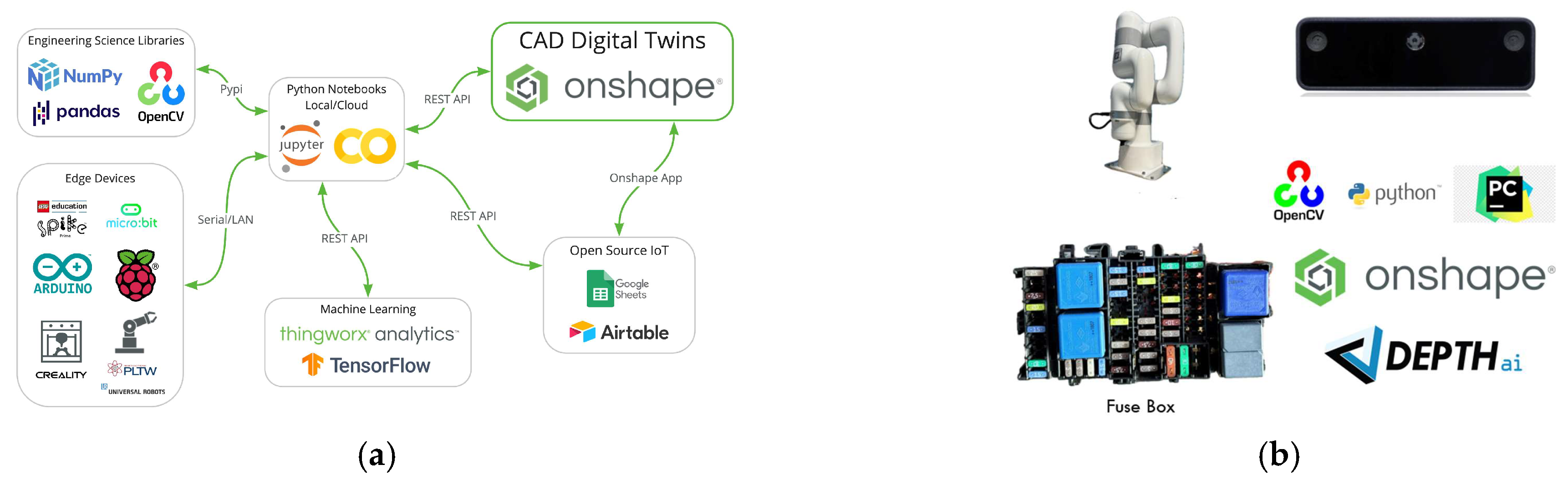
3.3.2. Tools and Software Used

  • Onshape is a SAS (Software as a Service);
  • PyCharm IDE (Python) 3.12.2;
  • Ufactory Studio 1.0.1;
  • Open CV 4.10.0.84;
  • Depth AI 3.5.0.
The workflow in Figure 2 outlines the key phases of the process for automating the insertion of fuses into wiring boxes, utilizing API technology for digital twin integration and robotic automation. The steps are organized as follows:
  • Creating the digital twin model using API technology: In this initial phase, a virtual replica of the wiring box assembly is created. The digital twin model is crucial for simulating and monitoring the assembly process in real time. Tools like Onshape are used for 3D modeling, enabling the reverse engineering of the physical wiring box to generate its digital counterpart.
  • Configuring and integrating the Ufactory Lite 6 robot: In this phase, the robotic arm is set up, including the calibration of the custom gripper and the initialization of the arm’s position. The precise configuration of the robot is essential to ensure the accurate assembly of fuses. Software like Ufactory Studio is used to configure the robot, while Python is employed to develop control programs that synchronize the robot’s movements with the digital twin.
  • Testing and calibrating the system using computer vision and digital twin: After configuring the robot and digital twin, this phase focuses on testing the system’s accuracy and efficiency. OpenCV and DepthAI are used for image processing, allowing the robot to leverage computer vision to identify and correctly position the fuses. Calibration ensures that the robot applies the right amount of force during insertion, preventing errors.
Each of these steps is organized sequentially to progressively develop and refine the automated process, starting with virtual modeling and setup, followed by real-world integration and testing. These tools are crucial for simulating the workflow, controlling the robotic arm, and ensuring precision during the assembly process.

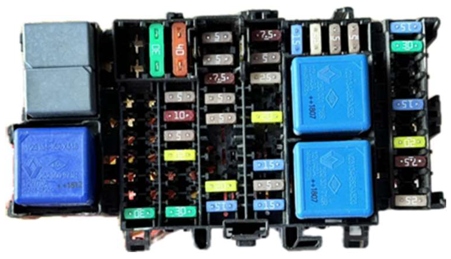
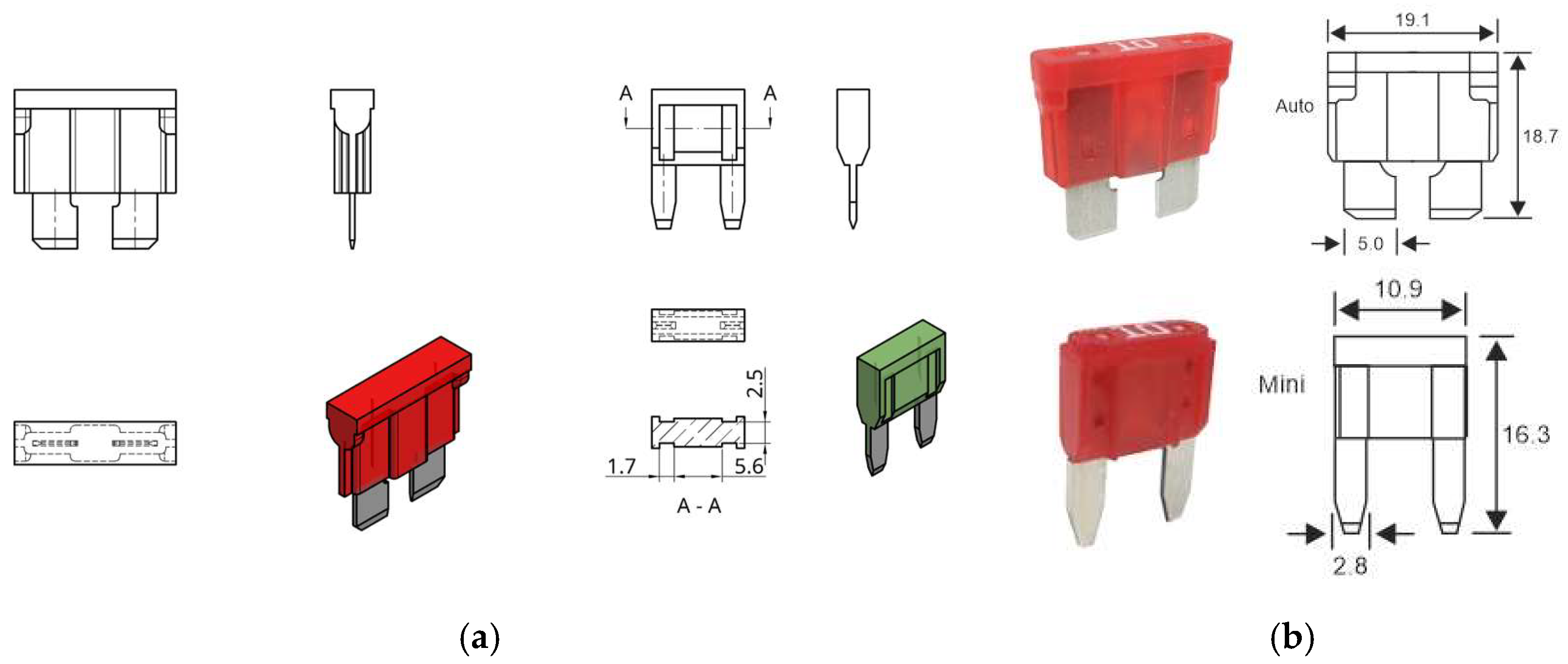
4. Proof of Concept for Optimizing Assembly in Wiring Boxes

For this proof of concept (POC), the following tools were used: modeling was done in the Onshape application using reverse engineering, and the software application to control the robotic arm was developed using Onshape, computer vision, and API technology for the digital twin. In the first stage, the proof of concept was focused on assembling the fuse in the wiring boxes (Figure 3), as these components are particularly difficult to assemble due to their small size.
The box used in this proof of concept contained the following fuses:
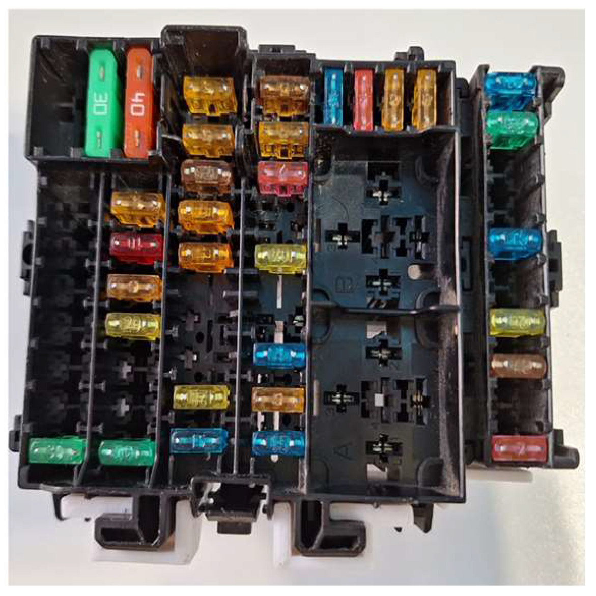
  • 10 mini blade fuses 5A;
  • 3 mini blade fuses 7.5A;
  • 1 mini blade fuse 10A;
  • 6 mini blade fuses 15A;
  • 4 mini blade fuses 20A;
  • 3 mini blade fuses 25A;
  • 3 mini blade fuses 30A;
  • 1 auto blade fuse 30A;
  • 1 auto blade fuse 40A.

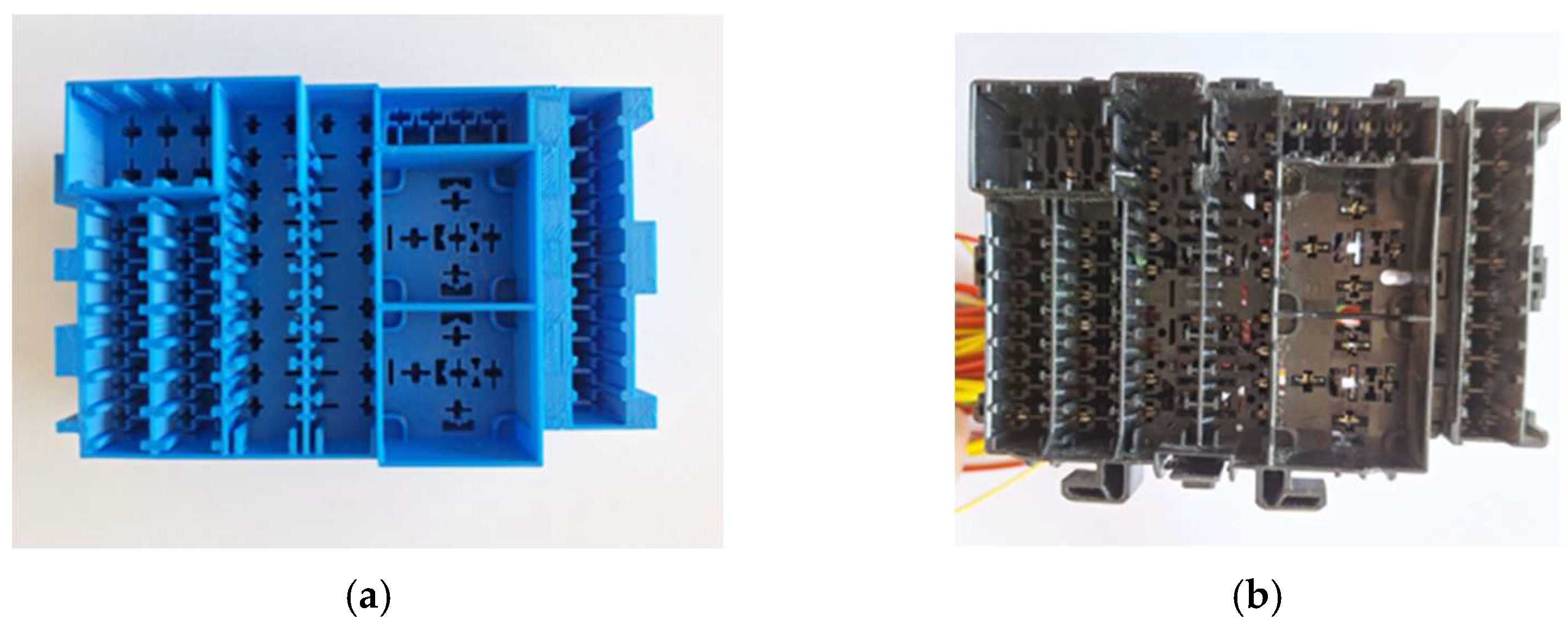
4.1. Creating the Digital Twin Model Using API Technology

The 3D model of the real wiring boxes (Figure 4) was made using reverse engineering in the Onshape application. This printed model of wiring boxes was used in the preliminary tests.
The dimensions for the fuses used in that box are presented in the next figure. In Figure 5a, only the necessary dimensions for defining the gripper have been provided. The remaining dimensions conform to the actual model. In this case study, new fuses were used, as well as the original wiring box, to achieve optimal results.
Due to the small size of the resistors, it was necessary to design and 3D print a gripper that was adapted to the dimensions of the two types of resistors that were previously presented in order to create the proof-of-concept prototype; the execution drawing of the gripper arm is presented in Figure 6.
Figure 7 presents how the gripper arm holds the fuse.
After the wiring box model was created and printed, the fuses were created in the virtual model. Using the same application, Onshape, the fuses were assembled in their place, taking into account the real model (Figure 8).
Mate connectors [21] (local coordinate systems) were placed in the exact center of the assembled fuses to allow for the extraction of the coordinates of each fuse, related to the origin (the mate connector of the gripper in the 0 position—Figure 9).
The setup made for digital twin is presented in Figure 9. The setup for creating a digital twin is designed as follows: the fuses will be taken from a fixed point that was previously established in the storage location (the white locations where the fuses are inserted). Each type of fuse has its own column where it is stored. The robot, using computer vision, identifies where the fuse is and knows its type based on its location. The robotic arm takes the fuse and places it in the designated location in the box, as determined by the program.
The system uses computer vision algorithms to identify the fuses in the environment. This process starts with image capture from a high-resolution camera, followed by image processing techniques like edge detection and shape recognition. The algorithm then classifies the fuses based on predefined attributes such as size, shape, and color. Once the fuses are identified, their positions are calculated relative to the robotic arm’s reference frame using transformation matrices. This positional data is then sent to the robot’s control system, enabling the arm to adjust its movements for precise grasping and insertion.
The identified positions of the fuses are translated into the robotic arm’s reference frame using kinematic transformations. This enables the robotic arm to move precisely toward the fuses, grasp them, and perform the insertion process with minimal error. By continuously updating the arm’s movements based on real-time feedback, the system ensures accuracy even in dynamic environments.
The robot places the fuse in its location in the box and releases it at only 2 mm inside the location. After the release, the robot raises the gripper to a safe distance, rotates the gripper 90 degrees, and presses the fuse into the location with the gripper closed and turned perpendicular to the fuse. This way, the robot controls precisely the amount of force applied to each fuse, without the risk of the fuse slipping inside the gripper.
In support of the points mentioned above, we have a video documenting the entire process, which is included as a Supplementary Material to the manuscript. This video offers a detailed view of the procedure, including the precise placement of the fuse, its release, and the pressing action performed by the robotic arm.
Mate connectors in Onshape serve as local coordinate systems and are used to define the position and orientation of parts within assemblies. By aligning these connectors, you can determine the global coordinates of parts [22].
To calculate the coordinates of each fuse relative to the origin (the gripper’s mate connector in the 0 position), it is necessary to consider the following:
  • The local coordinates of each mate connector on the fuse within the fuse’s local coordinate system.
  • Transforming the local coordinates of the fuse into global coordinates (relative to the origin).
The transformation formula is
P g l o b a l = T 3 D f u s e P l o c a l
  • P l o c a l is the position of a mate connector on the fuse in local coordinates. The coordinates of the point in the fuse’s coordinate system (which is at the center).
  • T 3 D f u s e is the transformation matrix (including rotation and translation) that converts the fuse’s local coordinates into global coordinates.
  • P g l o b a l is the position of a mate connector on the fuse in global coordinates.
The transformation matrix T 3 D f u s e can be decomposed into two components, rotation R 3 D f u s e and translation t 3 D f u s e :
T 3 D f u s e = R 3 D f u s e t 3 D f u s e 0 1
where R 3 D f u s e is a 3 × 3 matrix and t 3 D f u s e is a 3 × 1 vector.
T 3 D f u s e = R 11 R 12 R 21 R 22 R 31 R 32 0 0 R 13 t x R 23 t y R 33 t z 0 1  
  • R 3 D f u s e is the rotation matrix that defines the orientation of the fuse in the global system.
  • t 3 D f u s e is the translation vector that defines the position of the fuse’s center in the global system.
To obtain the coordinates of each fuse relative to the origin, these transformations for each fuse using their local coordinates and corresponding transformation matrices are applied.
The mate connectors will allow the robot to know exactly the address of each fuse location in the fuse box and also the exact location of each fuse available for assembly (in the fuse storage). Even though computer vision is used to detect the fuse in the storage, the exact position is needed so that the experimental gripper can correctly extract the fuse from the storage location and insert it into the fuse box.
Mate connectors in Onshape serve as orientation systems that were added to each fuse, ensuring the precise positioning of the fuses in the boxes with zero tolerance. These connectors represent the theoretically exact positions of the fuses. A mate connector was added to one fuse of each type, and once the fuse box was populated in CAD with all the fuses, we had access to each of these orientation systems. This allowed us to use the transformation formulas to determine the exact location of each fuse. These positions were then used as targets for the gripper and to guide the robot’s movements.
Regarding the tolerances of the fuses in the box, the chamfered shape of the fuses and the flexibility of the metallic connectors in the box slots ensured that the robotic arm’s maximum repeatability error did not impact the assembly process. This flexibility allowed for a smooth insertion and reliable assembly even with minor positional variations.
Digital twin, made by API technology, represents an advanced solution for monitoring and controlling the resistor mounting process in the wiring box. A digital twin creates a virtual replica of the entire physical process, allowing for the real-time tracking of each stage of assembly. By integrating sensors and real-time data, this digital model can detect and analyze variations and anomalies in the process, thereby optimizing performance and reducing errors.
APIs facilitate interconnections between various systems and devices, ensuring the smooth and efficient communication of data to the digital twin. Thus, quick and informed decisions can be made for adjustments in real time, maintaining the quality and reliability of the assembly. Also, digital twin enables simulations and test scenarios, anticipating potential problems and implementing preventive solutions. In conclusion, using a digital twin to mount fuses in the wiring box provides increased the control and continuous monitoring, leading to a more efficient and safer process.

4.2. Configuring and Integrating the Ufactory Lite 6 Robot

The first step was to configure the custom gripper arm. The payload weighed 0.27 kg, and the coordinates were Cx = 0 mm, Cy = 0 mm, and Cz = 30 mm.
The second step was to set up the origin, the initial position. It is very important for the robot to always start from the same position. This leads to higher precision in the assembly of fuses. This sets up the initial conditions and calibrates the robotic arm to ensure it starts from the correct position every time. The initial position parameters were x = 93.2 mm, y = 2 mm, and z = 71.6 mm.
After the collaborative robotic arm was configured, it was programmed using the Python programming language. The programming involved developing four programs:
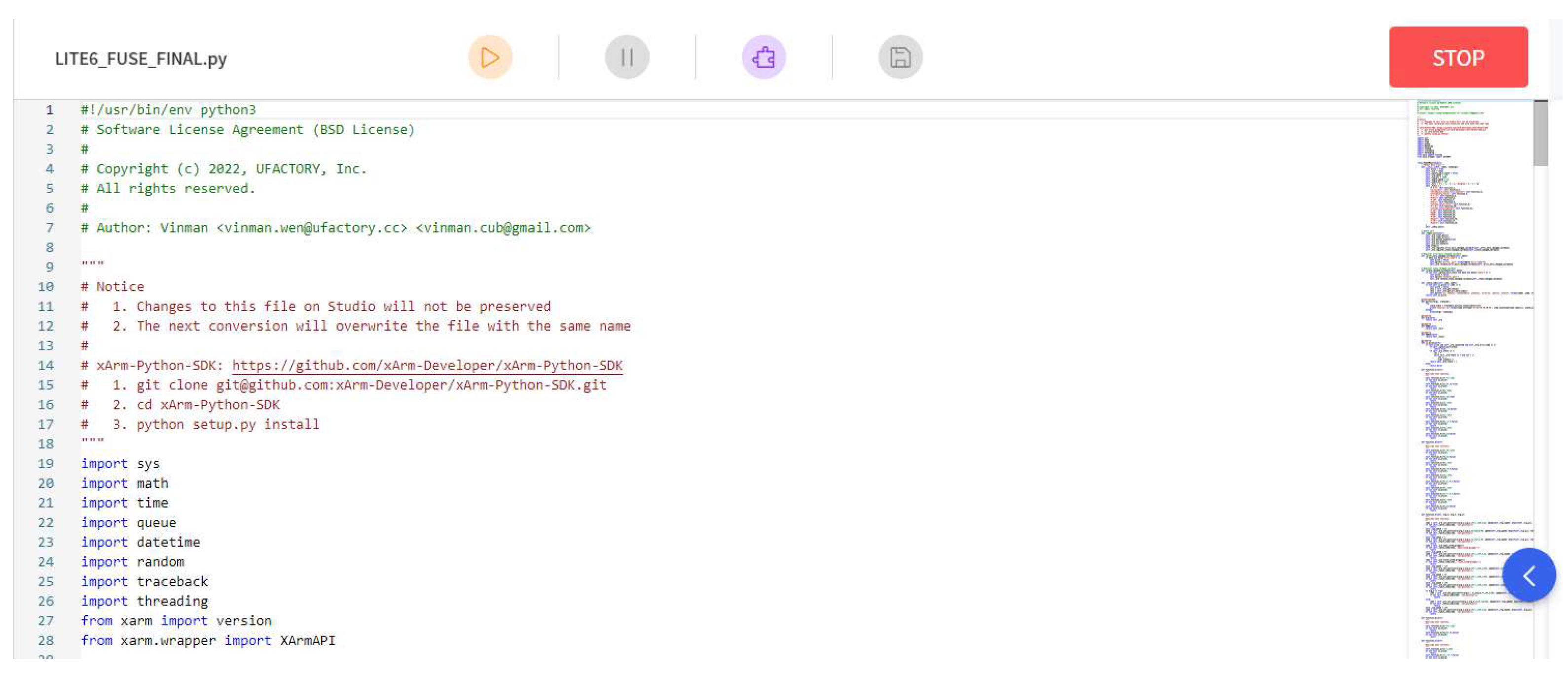
  • Fuse assembly program: This program handles the precise assembly of fuses, ensuring that each step is executed with accuracy. The program is sent to the robot using the Ufactory Studio 1.0.1. interface, Figure 10.
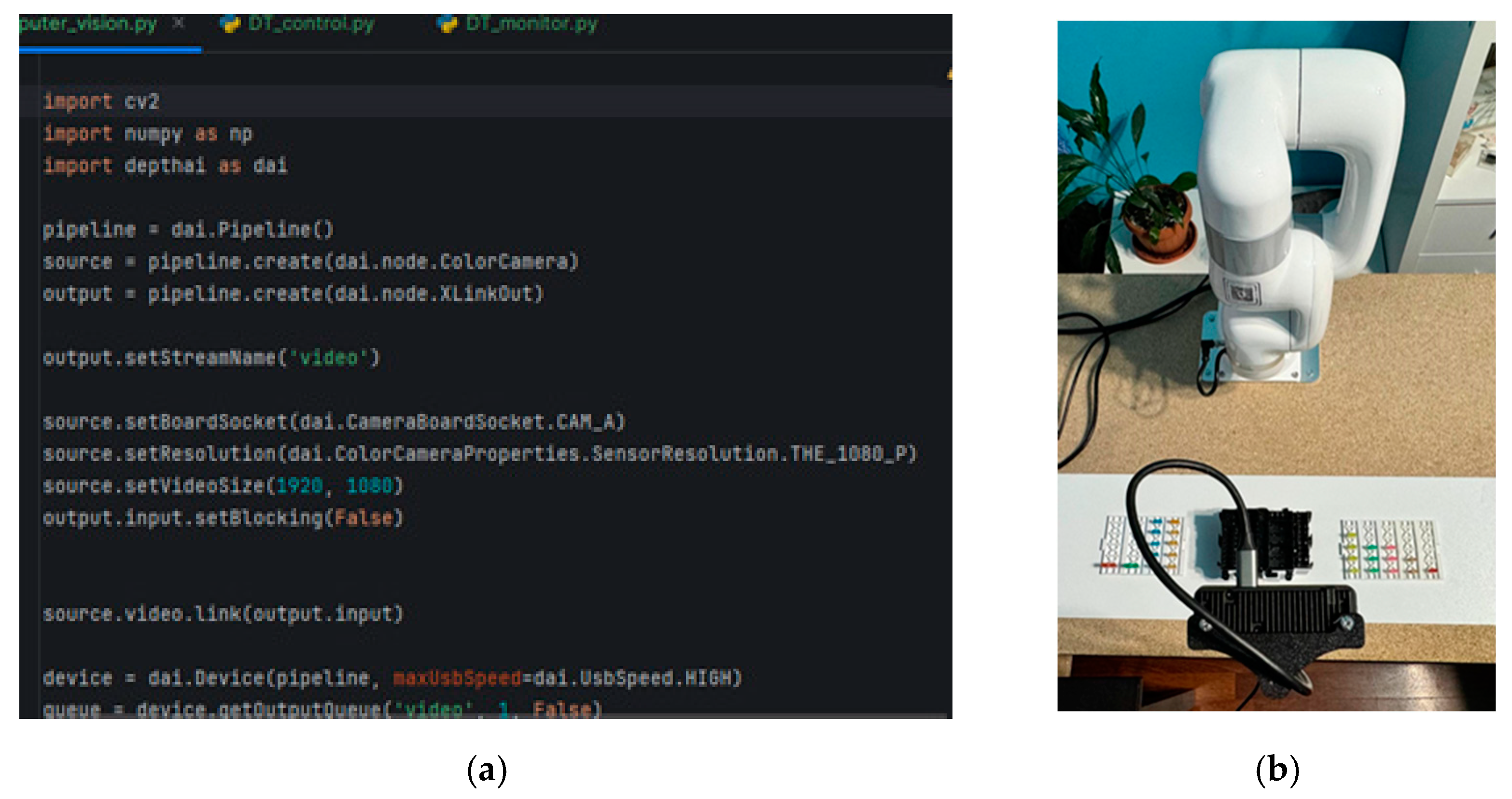
  • Computer vision program: Using an Oak-D Lite camera (Luxonis Holding Corporation, Littleton, CO 80127, USA) can identify the fuses in the storage location. This program is sent to the robot using the Pycharm platform, Figure 11.
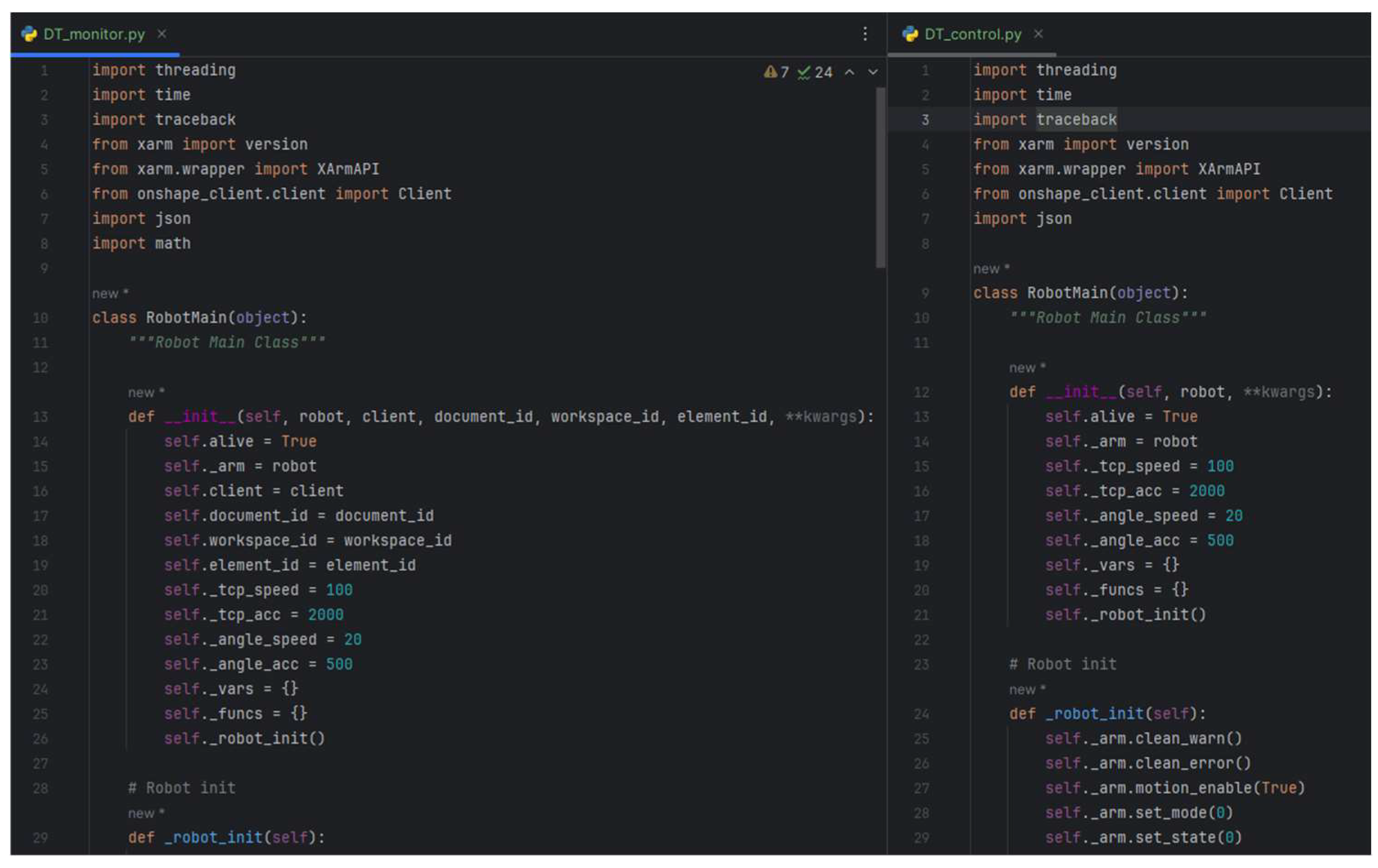
  • Digital twin monitoring program: This program monitors the robot’s activity during assembly. It is sent to the robot using the Pycharm platform, Figure 12.
  • Digital twin control program: This program allows us to control the robot’s activity from CAD environment on a computer. It is sent to the robot using the Pycharm platform, Figure 13.
The computer vision program uses the OpenCV library for image processing and DepthAI for interfacing with the camera.
The program is structured into several main sections:
  • DepthAI pipeline configuration: configuring the video source and output for video capture.
  • Video capture: initializing video capture from the default camera.
  • Image processing: applying filters to detect colors and identify fuses in boxes.
  • Object identification and marking: identifying and marking the positions of fuses in the video frame.
The next section configures the pipeline for DepthAI, setting up the camera, and the video output for image capture.
import cv2
import numpy as np
import depthai as dai
pipeline = dai.Pipeline()
source = pipeline.create(dai.node.ColorCamera)
output = pipeline.create(dai.node.XLinkOut)
 
output.setStreamName(‘video’)
source.setBoardSocket(dai.CameraBoardSocket.CAM_A)
source.setResolution(dai.ColorCameraProperties.SensorResolution.THE_1080_P)
source.setVideoSize(1920, 1080)
output.input.setBlocking(False)
source.video.link(output.input)
device = dai.Device(pipeline, maxUsbSpeed=dai.UsbSpeed.HIGH)
queue = device.getOutputQueue(‘video’, 1, False)
Video capture from the default camera is initialized using OpenCV 4.10.0.84.
cap = cv2.VideoCapture(0)
For image processing, color ranges in the HSV space are defined for different colors of interest (green, brown, and blue).
The frame processing function applies the color mask to each video frame and identifies and counts the fuses within predefined rectangles, marking them based on the presence of colors.
The program uses computer vision techniques to detect and count fuses in cable boxes. This approach automates the assembly process, reducing human errors and increasing production efficiency.
APIs (Application Programming Interfaces) are essential for the interaction between software and hardware, allowing the exchange of data and commands between different components of the system. In our project, we use two main APIs:
  • xArm API—for controlling the robotic arm.
  • Onshape API—for monitoring and updating the digital model.
For controlling the robotic arm, we use the xArmAPI to interact with the xArm robotic arm. This API allows the initialization, control, and monitoring of the robotic arm’s status.
  • from xarm.wrapper import XArmAPI
  • arm = XArmAPI(‘Robot ID’, baud_checkset = False)
  • arm.connect()
  • arm.motion_enable(enable = True)
  • arm.set_mode(0)
  • arm.set_state(0)
In this code, we initialize the connection with the robotic arm, enable motion, set the operating mode, and set the initial state.
  • def sync_movements(self, joint_positions):
  for joint_position in joint_positions:
    if joint_position is not None and all(angle is not None for angle in joint_position):
      self.pprint(f“Moving to position: {joint_position}”)
      code = self._arm.set_servo_angle(angle=joint_position, is_radian = False)
      self._check_code(code, ‘set_servo_angle’)
      time.sleep(1)
    else:
      self.pprint(“Received invalid joint position: Contains None values”)
This function synchronizes the movements of the robotic arm with the specified joint positions, ensuring that the values are valid before sending the command.
Onshape is a cloud-based CAD platform that allows access to digital models through APIs. In the digital twin monitor program, we use the Onshape API to monitor the joint positions of the robotic arm and update the digital model.
  • def monitor_robot(self):
  while self.is_alive:
    joint_positions = self._arm.get_servo_angle(is_radian = False)
    self.pprint(f“Current joint positions: {joint_positions}”)
    joint_positions_rad = [angle * math.pi/180 for angle in joint_positions[1]]
    self.update_onshape(joint_positions_rad)
    time.sleep(0.1)
This function continuously monitors the joint positions of the robotic arm and converts them to radians to be sent to Onshape.
The next function updates the digital model in Onshape with the new joint positions, ensuring that all six joints are provided before sending the data.
  • def update_onshape(self, joint_positions):
  try:
    if len(joint_positions) >= 6:
      set_mate_values(self.client,
              joint_positions[0], # Base
              joint_positions[1], # Shoulder
              joint_positions[2], # Elbow
              joint_positions[3], # Wrist
              joint_positions[4], # Hand
              joint_positions[5]) # Gripper
    else:
      self.pprint(“Received invalid joint positions: Less than 6 joints”)
  except Exception as e:
    self.pprint(f“Failed to update Onshape: {e}”)
The continuous synchronization functionality ensures that changes in the physical environment are reflected in the digital model in real-time. In the digital twin control program, we have a continuous_sync function that handles this synchronization:
  • def continuous_sync(client, arm, document_id, workspace_id, element_id, interval = 5):
  robot_main = RobotMain(arm)
  last_joint_positions = None
  while True:
    assembly_data = get_assembly(client, document_id, workspace_id, element_id)
    if assembly_data:
      joint_positions = extract_joint_positions(assembly_data)
 
      if joint_positions != last_joint_positions:
        print(“Detected changes in assembly, updating robot...”)
        robot_main.sync_movements(joint_positions)
        last_joint_positions = joint_positions
      else:
        print(“No changes detected in assembly.”)
    else:
      print(“Failed to retrieve assembly data”)
    time.sleep(interval)
This function continuously monitors the assembly data from Onshape and synchronizes the movements of the robotic arm accordingly.
By using the xArm and Onshape APIs, we have created a digital twin system capable of controlling and monitoring the assembly of fuses in wiring boxes. This system ensures precise synchronization between the physical and digital environments, allowing efficient control and real-time monitoring.
During the development process, we considered several alternative solutions. One option was to explore different types of robotic arms and grippers with varying degrees of freedom to handle the fuse insertion process. After evaluating these alternatives, we concluded that the selected robotic system provided the best balance of precision, adaptability, and cost-effectiveness. We also evaluated manual assistance and hybrid systems, but a fully automated approach was determined to be the most effective for maximizing both efficiency and quality in fuse insertion.
For the precise positioning of the fuse box, we implemented a solution that combines accurate fixture setups with computer vision. This approach accommodates slight variations in the fuse box’s positioning without the need for a dedicated jig, providing greater flexibility for different box configurations. While using a jig is a valid option for stabilizing the fuse box, especially in repetitive tasks, the flexible approach using visual feedback from the robotic system enhances adaptability. This flexibility allows the system to handle various fuse box configurations, making it a more versatile solution in dynamic production environments.

4.3. Testing and Calibrating the System Using Computer Vision and Digital Twin

The integration of computer vision and digital twin technologies in the assembly process of fuses in cable boxes significantly improves testing and calibration. This approach enhances accuracy, reduces human errors, and increases efficiency, leading to a more reliable and streamlined production line.
Figure 14 represents the case study focused on the automated assembly of fuses in wiring boxes, utilizing computer vision and digital twin technologies. This approach aims to enhance the accuracy, efficiency, and reliability of the manufacturing process.
The image shows a top-down view of an assembly station for fuses in wiring boxes. The setup includes a structured arrangement of fuses on either side of a central black housing component, likely a wiring box.
Components and arrangement:
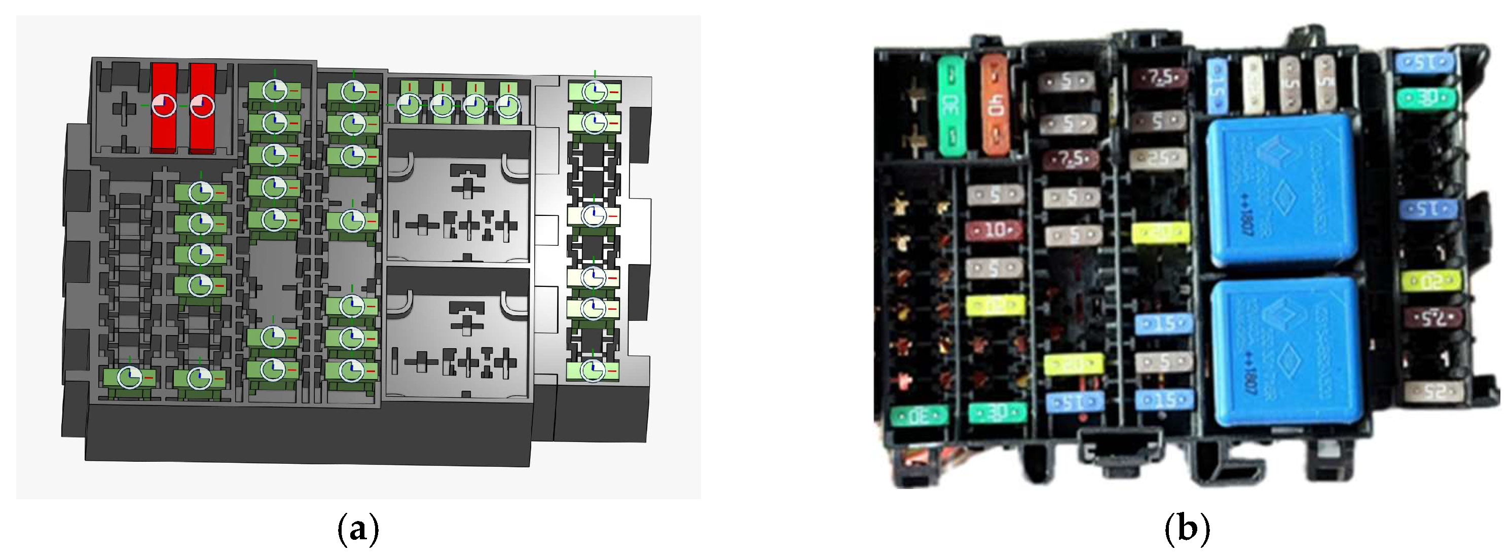
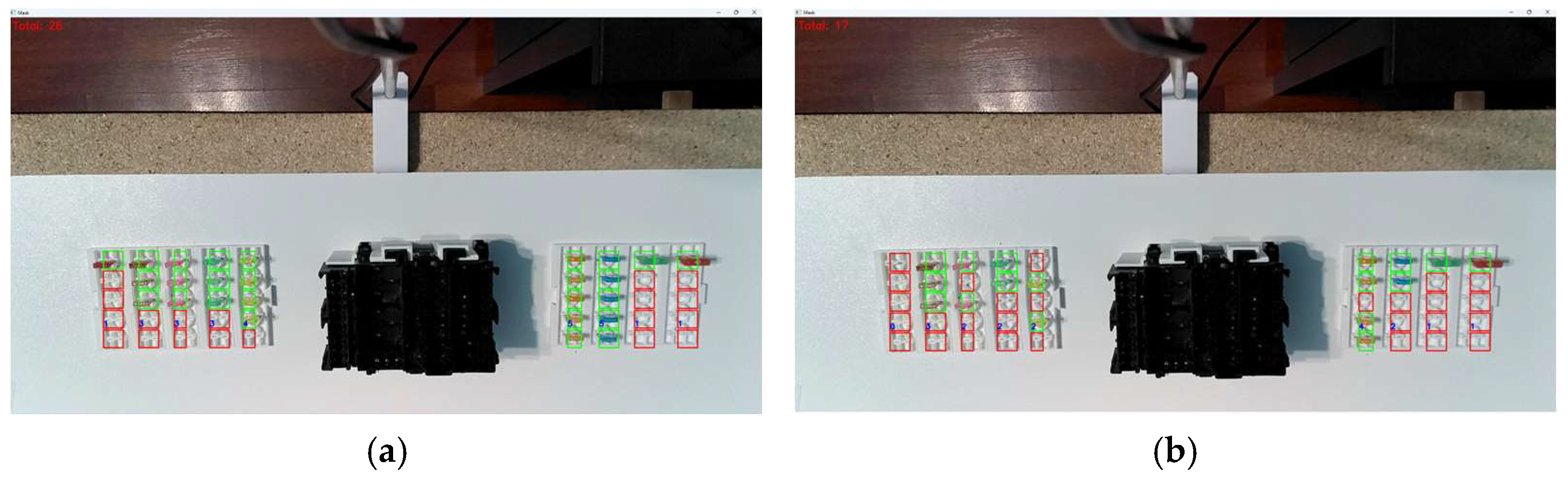
  • Fuses: The fuses are organized in a grid-like pattern, with red and green indicators. The red color indicates the absence of a fuse, while the green color indicates the presence of a fuse.
  • Wiring box: The black component in the middle is likely the main housing for the cable connections, serving as the central point for the fuse assembly.
  • Workspace: The assembly takes place on a white surface, providing a clear and contrasting background for image processing.
Computer vision techniques are used to identify, analyze, and count the fuses (as shown in Figure 14). The system detects fuses based on their color, shape, and position. The numbers “Total: 26” and “Total: 17” at the top left corner suggest the total count of detected fuses.
The digital twin technology is likely used to create a virtual replica of the physical assembly process. This virtual model allows for real-time monitoring, simulation, and optimization.
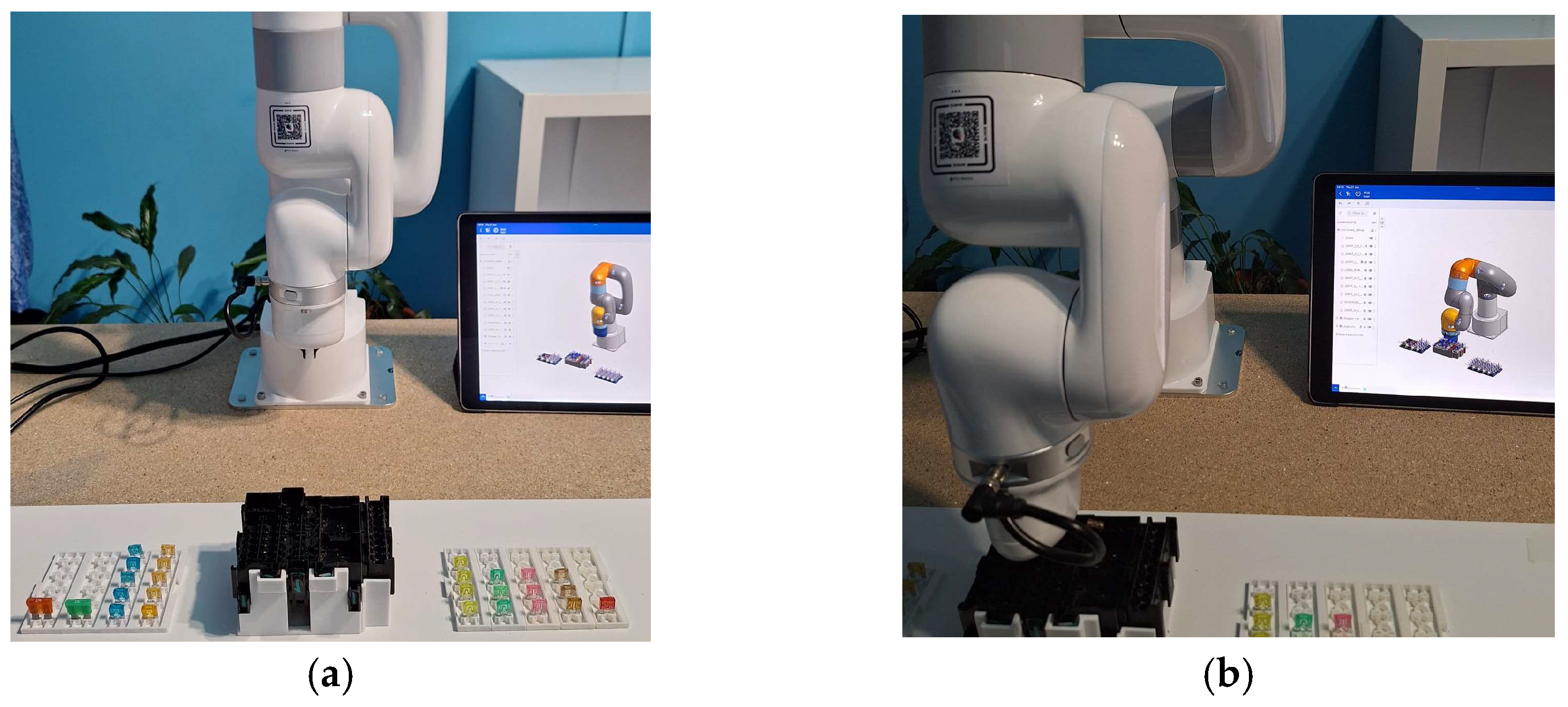
  • Real-time monitoring: the digital twin mirrors the real-world setup, providing continuous feedback and ensuring the assembly process is on track.
  • Simulation and optimization: by simulating the assembly process, potential issues can be predicted and addressed before they occur in the real world.
The images exemplify the application of advanced technologies in the assembly of fuses in cable boxes. By leveraging computer vision for accurate detection and counting and digital twin for real-time monitoring and optimization, this project aimed to achieve a highly efficient and reliable manufacturing process. This innovative approach not only enhances productivity but also ensures high standards of quality and precision in the assembly of cable boxes.

5. Results

The results achieved from automating the assembly process in wiring boxes using API technology for digital twin are as follows:
  • Novelty of the approach: this study is the first to apply a fully automated, digitally controlled process for fuse insertion, Figure 15, which solves existing quality and performance issues.
  • Accuracy and precision: The robotic system, integrated with digital twin technology, achieved a fuse insertion accuracy rate of 99.5%. This represents a significant improvement over manual insertion, which often results in misalignments such as angled or incomplete insertion, leading to a suboptimal electrical contact and potential rework. By utilizing real-time feedback from the digital twin, the automated system consistently ensured that fuses were inserted at the correct angle and depth, mitigating the common errors associated with manual assembly.
  • Force control and component integrity: Another critical factor in the automation process was the precise control of insertion force. The system applied just enough pressure to secure the fuse without causing damage, Figure 16. This is an improvement over manual processes, where excessive or insufficient force often leads to defects or damaged components. The force applied by the robotic arm was consistently measured and controlled, ensuring the reliable and secure insertion of each fuse, thus enhancing the quality and reliability of the wiring box assembly.
  • Time efficiency: The cycle time for manual fuse insertion typically ranged between 40 and 45 s per fuse, depending on the operator’s skill and the complexity of the fuse box. With the automated system, this time was significantly reduced to 22–25 s per fuse, reflecting a nearly 50% improvement in efficiency. This reduction in cycle time was achieved without compromising accuracy or quality, making the automated process both faster and more reliable than manual alternatives.
  • System flexibility: The system demonstrated the flexibility to handle slight variations in fuse dimensions and box configurations. The combination of computer vision and digital twin technology allowed the system to adapt to these variations without requiring extensive recalibration or adjustments, showcasing its potential for handling different fuse box designs in dynamic production environments. The gripper design, optimized through iterative testing, enabled the robotic arm to handle delicate components with a minimal risk of damage.
  • Continuous operation and reliability: During extended testing, the system demonstrated high reliability, operating continuously over long periods without significant faults or errors. This robustness is crucial for its potential application in full-scale production environments, where continuous, uninterrupted operation is necessary to maintain productivity. The real-time monitoring capabilities of the digital twin allowed for ongoing adjustments to be made, ensuring optimal performance throughout the assembly process.
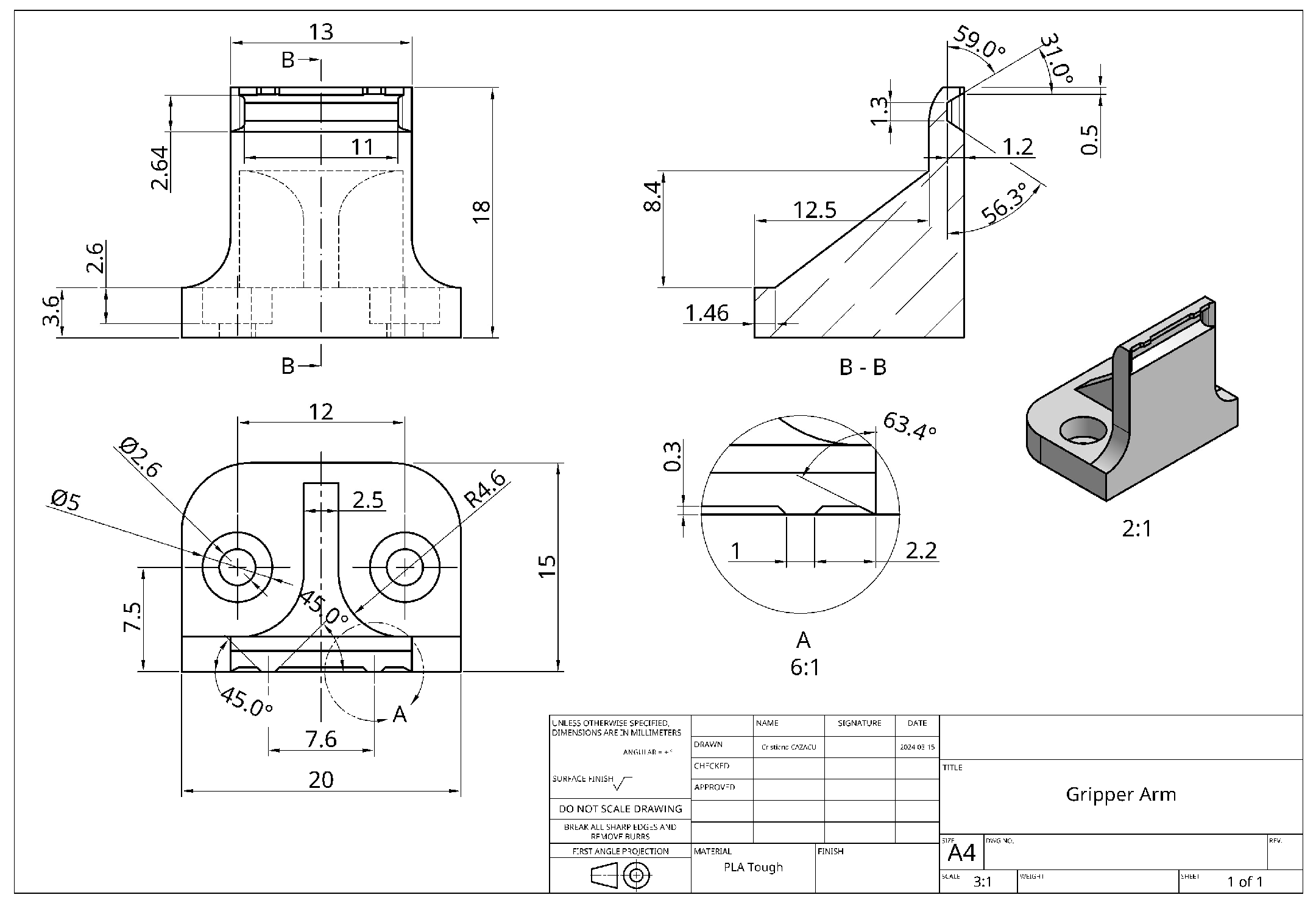
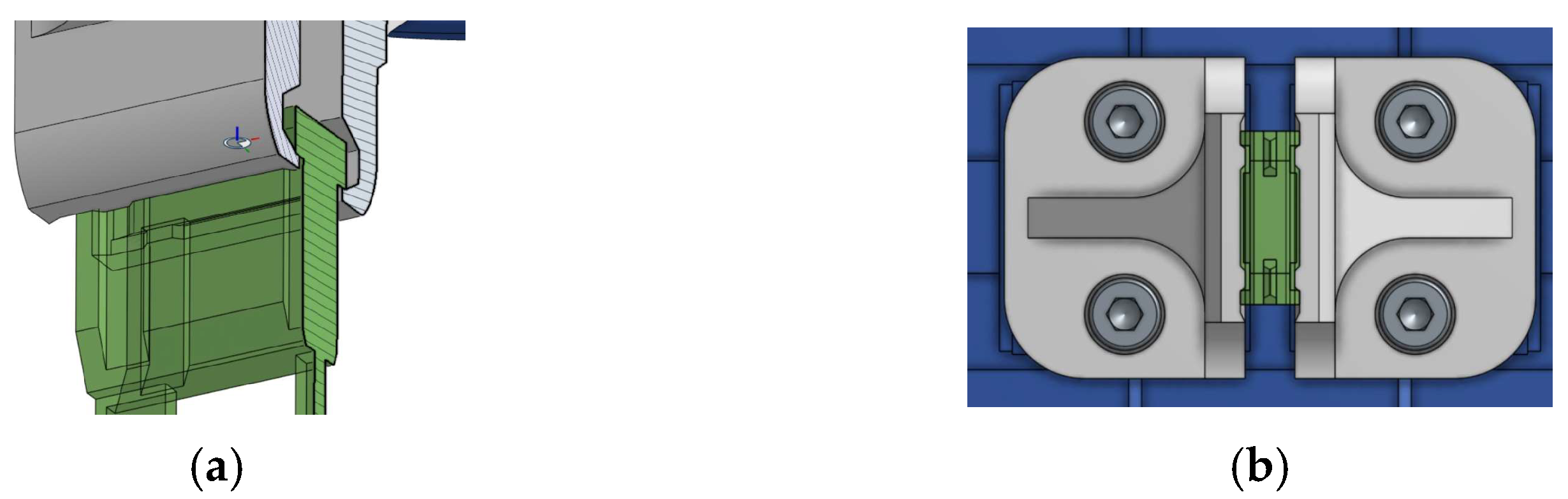
  • Gripper design optimization: The design of the gripper was optimized through multiple iterations to ensure that it could securely grasp the fuses without causing damage. The adjustments to the gripper’s shape and the force it applied were crucial for handling the small, sensitive components involved in the assembly process. This iterative testing led to a gripper design capable of maintaining a firm hold on each fuse while allowing precise control during insertion.
  • Scalability and adaptability: The system’s adaptability to different box configurations was another significant advantage. The automated process proved scalable and capable of handling various wiring box setups with minimal adjustments, making it suitable for a wide range of automotive applications. This scalability was further enhanced by the digital twin’s simulation capabilities, which allowed for the virtual testing of multiple scenarios, reducing the need for physical prototypes.
  • Statistical validation: The results were validated through multiple test cycles, typically ranging from 20 to 30 cycles per setup, to ensure consistency and reliability. Statistical methods, including mean and standard deviation calculations, were applied to metrics such as cycle time, insertion accuracy, and the force applied by the gripper. This rigorous approach ensured that the results were representative and not outliers, confirming the system’s high performance.
Overall, the project demonstrated the feasibility and benefits of automating the assembly of fuses in wiring boxes, setting the stage for further advancements and implementations in the industry.

6. Conclusions

Analyzing the state-of-the-art existing research in automation within wiring harness production, this study has led to the following innovative outcomes:
  • The paper proposes a novel approach to automate the insertion of fuses and relays using a robotic arm integrated with API technology for digital twin simulation and optimization. The main scientific contribution is the integration of a digitally real-time monitored, fully adaptive robotic system that ensures precise insertion angles and force application.
  • This research introduces a novel methodological framework in which a digital twin not only simulates but actively controls the assembly process through real-time data feedback. This reduces reliance on post-production quality checks, thus enhancing both production speed and product reliability. The study also introduces a new scientific framework for real-time process adjustment using digital twin models.
  • This work significantly contributes to the broader field of smart manufacturing and Industry 4.0. It demonstrates how integrating API technology with robotic systems can yield adaptive, real-time production systems. This paves the way for future studies to apply similar concepts to other complex manual assembly processes, potentially revolutionizing the field.
Consequently, based on the objectives achieved so far in automating the assembly of fuses for a specific type of box, here are some suggested areas for future research:
  • Expand automation to handle diverse box types with adaptable algorithms and robotic systems for increased flexibility and scalability.
  • Predictive maintenance is a key area for further development, as it was not fully implemented in this study but was identified as a promising application of digital twin technology. Future work could focus on integrating predictive maintenance to improve the system’s ability to monitor wear and tear on robotic components, predict potential failures, and proactively schedule maintenance tasks. This would help reduce downtime and enhance overall system reliability.
  • Integrate digital twin and IoT for real-time monitoring, optimizing operational efficiency, predictive maintenance, and assembly line optimization.
  • Enhance robotic gripper design to improve delicate component handling, experimenting with materials and designs for better reliability.
  • Implement continuous improvement through iterative testing, refining the automated system based on performance data to meet evolving industry needs.
  • In this study, the robot was programmed offline, using API technology and digital twin integration to simulate and optimize the assembly process before its physical implementation. This approach allowed us to test multiple scenarios and refine the robot’s movements without disrupting the production process. While offline programming provided the advantage of optimizing complex operations in a controlled environment, we recognize that online programming, which allows for real-time adjustments directly on the robot, could offer greater flexibility and faster on-site modifications.
Although this study did not include a direct comparison between offline and online programming, we acknowledge that such a comparison could offer valuable insights into differences in cycle time, ease of use, and operational flexibility. This is an area of potential exploration in future research, where both approaches could be tested under the same conditions to assess their respective benefits and limitations.

Supplementary Materials

The supporting information can be downloaded at: https://youtu.be/sTRLN013qUQ (accessed on 3 October 2024).

Author Contributions

Conceptualization, C.-C.C. and I.I.; methodology, C.-C.C.; software, C.-C.C.; validation, C.-C.C., I.I. and R.C.P.; formal analysis, C.-C.C., I.I., R.C.P. and C.L.P.; investigation, C.-C.C., I.I. and R.C.P.; resources, C.-C.C.; writing—original draft preparation, C.-C.C., I.I. and C.L.P.; writing—review and editing, C.L.P. and C.E.C.; supervision, C.E.C.; project administration, C.-C.C.; funding acquisition, C.-C.C. All authors have read and agreed to the published version of the manuscript.

Funding

This work was supported by a grant from the National Program for Research of the National Association of Technical Universities—GNAC ARUT 2023.

Institutional Review Board Statement

Not applicable.

Informed Consent Statement

Not applicable.

Data Availability Statement

The original contributions presented in the study are included in the article, further inquiries can be directed to the corresponding author.

Acknowledgments

Thanks to the students Hanga Mihail, Drăguțu Matei, and Nașu Teodor Cristian, students of the Faculty of Industrial Engineering and Robotics, specializing in Applied Computer Science in Industrial Engineering, for their assistance in programming the robotic arm and conducting the initial tests.

Conflicts of Interest

The authors declare no conflicts of interest. The funders had no role in the design of the study; in the collection, analyses, or interpretation of data; in the writing of the manuscript; or in the decision to publish the results.

References

  1. Eheim, M.; Kaiser, D.; Weil, R. On Automation Along the Automotive Wire Harness Value Chain. In Advances in Automotive Production Technology—Theory and Application; Weißgraeber, P., Heieck, F., Ackermann, C., Eds.; ARENA2036; Springer: Berlin/Heidelberg, Germany, 2021; pp. 178–186. [Google Scholar] [CrossRef]
  2. Govoni, A.; Laudante, G.; Mirto, M.; Natale, C.; Pirozzi, S. Towards the Automation of Wire Harness Manufacturing: A Robotic Manipulator with Sensorized Fingers. In Proceedings of the 9th International Conference on Control, Decision and Information Technologies (CoDIT), Rome, Italy, 3–6 July 2023. [Google Scholar] [CrossRef]
  3. Ștefan, I.; Popescu, A.C.; Popa, L.C.; Dobrescu, T.G.; Coteț, C.E. Research regarding assembly flow optimization of wiring harness in automotive industry. MATEC Web Conf. 2021, 343, 02003. [Google Scholar] [CrossRef]
  4. Heisler, P.; Steinmetz, P.; Yoo, I.S.; Franke, J. Automatization of the Cable-Routing-Process within the Automated Production of Wiring Systems. Appl. Mech. Mater. 2017, 871, 186–192. [Google Scholar] [CrossRef]
  5. Heisler, P.; Kuhn, M.; Süß-Wolf, R.; Franke, J. Innovative Solutions for the Covering Process in the Manufacturing of Wire Harnesses to Increase the Automation Degre. In Proceedings of the IEEE 11th International Conference on Mechanical and Intelligent Manufacturing Technologies (ICMIMT), Cape Town, South Africa, 20–22 January 2020. [Google Scholar] [CrossRef]
  6. Bi, Z.; Pomalaza-Ráe, C.; Hershberger, D.; Dawson, J.; Lehman, A.; Yurek, J.; Ball, J. Automation of Electrical Cable Harnesses Testing. Robotics 2018, 7, 1. [Google Scholar] [CrossRef]
  7. Salunkhe, O.; Stahre, J.; Romero, D.; Li, D.; Johansson, B. Specifying Task Allocation in Automotive Wire Harness Assembly Stations for Human-Robot Collaboration. Comput. Ind. Eng. 2023, 184, 109572. [Google Scholar] [CrossRef]
  8. Navas-Reascos, G.; Romero, D.; Stahre, J.; Caballero-Riuz, A. Wire Harness Assembly Process Supported by Collaborative Robots: Literature Review and Call for R&D. Robotics 2022, 11, 65. [Google Scholar] [CrossRef]
  9. Román-Ibáñez, V.; Pujol, F.A. Collaborative robotics in wire harnesses spot taping process. Comput. Ind. 2021, 125, 103370. [Google Scholar] [CrossRef]
  10. Thelen, A.; Zhang, X.; Fink, O.; Lu, Y.; Ghosh, S.; Youn, B.D.; Todd, M.D.; Mahadevan, S.; Hu, C.; Hu, Z. A comprehensive review of digital twin—Part 1: Modeling and twinning enabling technologies. Struct. Multidiscip. Optim. 2022, 65, 354. [Google Scholar] [CrossRef]
  11. Thelen, A.; Zhang, X.; Fink, O.; Lu, Y.; Ghosh, S.; Youn, B.D.; Todd, M.D.; Mahadevan, S.; Hu, C.; Hu, Z. A Comprehensive Review of Digital Twin—Part 2: Roles of Uncertainty Quantication and Optimization, a Battery Digital Twin, and Perspectives. Struct. Multidiscip. Optim. 2022, 66, 1. [Google Scholar] [CrossRef]
  12. Garg, G.; Kuts, V.; Anbarjafari, G. Digital Twin for FANUC Robots: Industrial Robot Programming and Simulation Using Virtual Reality. Sustainability 2021, 13, 10336. [Google Scholar] [CrossRef]
  13. Barricelli, B.R.; Casiraghi, E.; Fogli, D. A Survey on Digital Twin: Definitions, Characteristics, Applications, and Design Implications. IEEE Access 2019, 7, 167653–167671. [Google Scholar] [CrossRef]
  14. Erdei, T.I.; Krakó, R.; Husi, G. Design of a Digital Twin Training Centre for an Industrial Robot Arm. Appl. Sci. 2022, 12, 8862. [Google Scholar] [CrossRef]
  15. Popescu, D.; Dragomir, M.; Popescu, S.; Dragomir, D. Building Better Digital Twins for Production Systems by Incorporating Environmental Related Functions—Literature Analysis and Determining Alternatives. Appl. Sci. 2022, 12, 8857. [Google Scholar] [CrossRef]
  16. Iliuță, M.E.; Moisescu, M.A.; Pop, E.; Ioniță, A.D.; Caramihai, S.I.; Mitulescu, T.C. Digital Twin—A Review of the Evolution from Concept to Technology and Its Analytical Perspectives on Applications in Various Fields. Appl. Sci. 2024, 14, 5454. [Google Scholar] [CrossRef]
  17. Ufactory Lite 6—User Manual V2.0.0. Available online: https://www.ufactory.cc/wp-content/uploads/2023/05/Lite6-User-Manual-V2.0.0.pdf (accessed on 3 February 2024).
  18. Ufactory Lite 6—DH Parameters. Available online: https://www.ufactory.cc/wp-content/uploads/2023/04/Kinematic-and-Dynamic-Parameters-of-UFACTORY-Lite-6.pdf (accessed on 2 February 2024).
  19. Modi, P.P.; Sunny, M.S.H.; Khan, M.M.R.; Ahmed, H.U.; Rahman, M.H. Interactive IIoT-based 5DOF Robotic Arm for Upper Limb Telerehabilitation. IEEE Access 2022, 10, 114919–114928. [Google Scholar] [CrossRef]
  20. Onshape Digital Twins|Digital Transformation in Education. Available online: https://ptc-education.github.io/docs/solutions/onshapedx (accessed on 4 February 2024).
  21. Swe-Check—Blade Fuse Sizes. Available online: https://www.swe-check.com.au/editorials/blade_fuse_sizes.php (accessed on 15 February 2024).
  22. Onshape—Mate Connectors. Available online: https://cad.onshape.com/help/Content/mateconnector.htm (accessed on 4 March 2024).
Figure 1. Technical representation for Ufactory Lite 6: (a) a description of the precise dimensions, (b) the isometric view of the robot [17].
Applsci 14 09483 g001
Figure 2. Tools and software: (a) digital twins created using Onshape [20], (b) our case study.
Applsci 14 09483 g002
Figure 3. Real fuse box with fuses and relays.
Applsci 14 09483 g003
Figure 4. Wiring/fuse box: (a) 3D-printed model, (b) real fuse box.
Applsci 14 09483 g004
Figure 5. Fuse dimensions: (a) virtual 3D model, (b) real model [18].
Applsci 14 09483 g005
Figure 6. The execution drawing of the gripper.
Applsci 14 09483 g006
Figure 7. The gripper arm holds the fuse: (a) the isometric section, (b) the view from the fuse box.
Applsci 14 09483 g007
Figure 8. Fuses: (a) 3D, virtual fuse models, (b) real fuses.
Applsci 14 09483 g008
Figure 9. Creating a digital twin: (a) 3D, virtual models, (b) real model.
Applsci 14 09483 g009
Figure 10. Fuse assembly program—Ufactory studio interface.
Applsci 14 09483 g010
Figure 11. Computer vision program: (a) Pycharm program, (b) setup camera.
Applsci 14 09483 g011
Figure 12. Digital twin monitor and control program.
Applsci 14 09483 g012
Figure 13. Example of digital twin assembling fuses by robot: (a) initial position, (b) work position.
Applsci 14 09483 g013
Figure 14. Computer vision identification: (a) 26 parts, (b) 17 parts.
Applsci 14 09483 g014
Figure 15. The wiring box with fuses assembled by robot.
Applsci 14 09483 g015
Figure 16. The message displayed to the user when the robot detects a force greater than necessary.
Applsci 14 09483 g016
Table 1. Hardware parameters, characteristics, and joints.
ParameterValue
DoF6
Reach440 mm
Payload600 g
Repeatability 0.5 mm
Speed500 mm/s
EOATISO9409-1-50 [17]
Motor typeDC Brushless
Control boxBuild-in/Integrated
I/O Parts (Base)8
I/O Parts (EOAT)4
Robot communicationPrivate TCP
Developing EnvironmentPython 3.12.2 /ROS/C++
GUIUfactory Studio
Weight7.2 kg
Maximum speed180°/s
Joint 1±360°
Joint 2±150°
Joint 3−3.5°–300°
Joint 4±360°
Joint 5±124°
Joint 6±360°
Table 2. Modified Denavit–Hartenberg Parameters for Lite 6 [18].
Joint (i)α (deg)a (mm)d (mm)θ (deg) *
100243.30
2−9000−90
31802000−90
49087227.60
590000
6−90061.50
* Joint angle (rotation around the z-axis).
Table 3. Standard Denavit–Hartenberg Parameters for Lite 6.
Joint (i)α (deg)a (mm)d (mm)θ (deg)
1−900243.30
21802000−90
390870−90
4900227.60
5−90000
60061.50
Disclaimer/Publisher’s Note: The statements, opinions and data contained in all publications are solely those of the individual author(s) and contributor(s) and not of MDPI and/or the editor(s). MDPI and/or the editor(s) disclaim responsibility for any injury to people or property resulting from any ideas, methods, instructions or products referred to in the content.

