Article

Structural Design and Study of an Integrated Cutter System Based on Machine Operation

1
China Railway 14th Bureau Group Corporation Limited, Jinan 250101, China
2
School of Mechanical Engineering, Dalian University of Technology, Dalian 116024, China
3
China Railway Construction Underwater Shield Tunnel Engineering Laboratory, Jinan 250101, China
*
Author to whom correspondence should be addressed.
Appl. Sci. 2024, 14(20), 9449; https://doi.org/10.3390/app14209449
Submission received: 28 August 2024 / Revised: 9 October 2024 / Accepted: 14 October 2024 / Published: 16 October 2024
(This article belongs to the Section Mechanical Engineering)

Abstract

:
In the process of shield tunneling, the cutter will inevitably be worn and damaged and will need to be replaced frequently. The low efficiency and high safety risk of traditional manual cutter change have prompted robotic cutter change to become the mainstream trend of current research. However, it is difficult to realize mechanical automation disassembly due to the existence of many fragmented parts and complex disassembly steps in the traditional cutter system. Therefore, this paper proposes an eccentric integrated cutter system, which greatly simplifies the disassembly process while retaining the excellent fastening structure of the traditional cutter system. The evaluation system of the cutter system was established through the analytic hierarchy process, and it was verified that the eccentric integrated cutter system has obvious superiority in realizing automated disassembly and assembly and, at the same time, that it has good structural strength. Finally, vibration experiments were carried out based on shield construction conditions. The experimental results show that after 14 h of continuous vibration, the residual preload ratio of the integrated cutter sample stabilized at more than 90%, which indicates good anti-loosening performance.

1. Introduction

In the construction of subway transportation, water pipelines and other urban tunneling projects, shield machines play a crucial role [1]. Shield machines mainly rely on the dense cutter system in a cutter plate to realize the cutting of rock and soil in front and complete the rock-breaking function. However, in the process of shield tunneling, machines need to face a variety of harsh service conditions, such as vibration impact, heavy load, sediment blockage, etc., and the cutter inevitably undergoes wear and damage and therefore needs to be regularly inspected and parts have to be replaced [2]. At present, manual cutter-change technology is mainly divided into atmospheric-pressure cutter-change technology and pressure cutter-change technology [3,4], such as compressed-air pressure cutter change, saturated submersible pressure cutter change, saturated gas pressure cutter change, atmospheric-pressure cutter change, frozen cutter-plate cutter change, and so on. Although the above technical solutions provide technical support for manual cutter change, reducing the difficulty and risk factor of cutter change, cutter changers still operate in a complicated environment with high pressure and high humidity, air pollution, etc., and may even face risky accidents, such as drilling-face collapse and mud backflow [5]. As the domestic and foreign research on unmanned and intelligent tunnel boring equipment continues to deepen, so the automation of cutter-change operations has become an inevitable trend to promote the development of tunnel boring technology. However, it is difficult to realize mechanical automation disassembly and assembly due to the existence of many fragmented parts and complicated disassembly steps in the traditional cutter system (TCS) [6]. Therefore, the design of a machine-friendly integrated cutter system (ICS) has an indispensable role in realizing automated cutter change in tunnel boring.
For the research on integrated cutter systems, many universities and companies have carried out research and development work. The early research of the French company BOUYGUES [7] and the German Research Center for Artificial Intelligence (DFKI) [8] is most prominent. BOUYGUES proposes a linkage-type integrated cutter system, which is used in conjunction with the cutter-changing robot TELEMACH. It works by rotating the screw at the top of the cutter system, which drives the linkage mechanism downward to realize cutter installation. This linkage-type integrated cutter system has the advantage of simple installation, but it is prone to jamming in the harsh environment of the shield machine [9]. The DFKI designed a slider-type integrated cutter system for use with the robot HECTOR. This also has the advantage of fewer disassembly processes, but the slider structure results in higher machining requirements and lower forces [10]. In recent research work, Hongrun Construction, in conjunction with Shanghai University [11,12], proposed an eccentric locking cutter system, which can realize the locking of the eccentric circular mechanism with the cutter box by grasping the cutter by the end-effector and rotating it at a certain angle. The Dalian University of Technology [13] designed a wedge swing-type cutter system, which is based on the action of the continuous ammunition supply mechanism of automatic firearms and transforms the lifting action into a wedge swing. The rotation of the bolt drives the fork to lift and move, realizing the retraction and unfolding of the locking wedge. Based on the contradiction solution theory of invention problem solving (TRIZ), Central South University [14] proposed a slide-groove-type cutter system. It consists of only four components and has a simple disassembly action.
In addition, during the service of a shield machine, the cutter system will be constantly affected by external environmental factors, such as impact load and vibration. The reaction force of the cutter breaking the rock is firstly transmitted to the cutter body through the cutter ring, then to the cutter shaft by the bearings in the cutter body and finally to the cutter holder, which is responsible for fastening the cutter shaft. Prolonged exposure of the cutter system to vibration can cause the fasteners in the system to loosen, which in turn can cause the cutter to disengage. This increases construction costs and may even lead to risky accidents. Therefore, when evaluating the reliability of a new cutter system, the fastening performance of the cutter holder structure is an important evaluation index.
At present, in the field of anti-loosening performance testing, universal test standards and testing methods applicable to complex fasteners, such as the integrated cutter system, have not been established. In the structural program of the EICS, since the fastening of the structure relies on the connection between the screw and the locking wedge, the anti-loosening performance of the screw is directly related to the fastening performance of the structure. The main forms of failure of the bolt connection are loosening, fatigue fracture, corrosion, etc., loosening occurring with the highest probability. The essential reason for bolt loosening is that with the growth of service time, the bolt preload gradually decreases to the thread self-locking limit, and relative displacement between the bolt and the nut begins to occur, resulting in a significant decrease in the fastening capacity [15].
In summary, the structural design of integrated cutter systems is still in the exploratory stage. In the face of the harsh working environment of shield tunneling machines, the reliability of the structural design of most cutter systems needs to be tested in actual engineering applications. In addition, most of the design schemes do not establish evaluation systems for cutter systems, such that the advantages of integrated cutter systems over traditional cutter systems cannot be visually compared. Therefore, this paper proposes an eccentric integrated cutter system and objectively evaluates the three cutter schemes based on the analytic hierarchy process (AHP) [16]. Finally, a vibration test is designed to verify the anti-loosening performance of the integrated cutter system. The main contents of this paper are as follows. The second part concerns the design of the integrated cutter system, which mainly includes the structural design and working principle of the three cutter systems. The third part describes the establishment of the analytic hierarchy process and the evaluation process for the three cutter solutions. The fourth part tests the anti-loosening performance of the integrated cutter system by vibration testing. The fifth part provides a summary and future prospects.

2. Integrated Cutter System Design

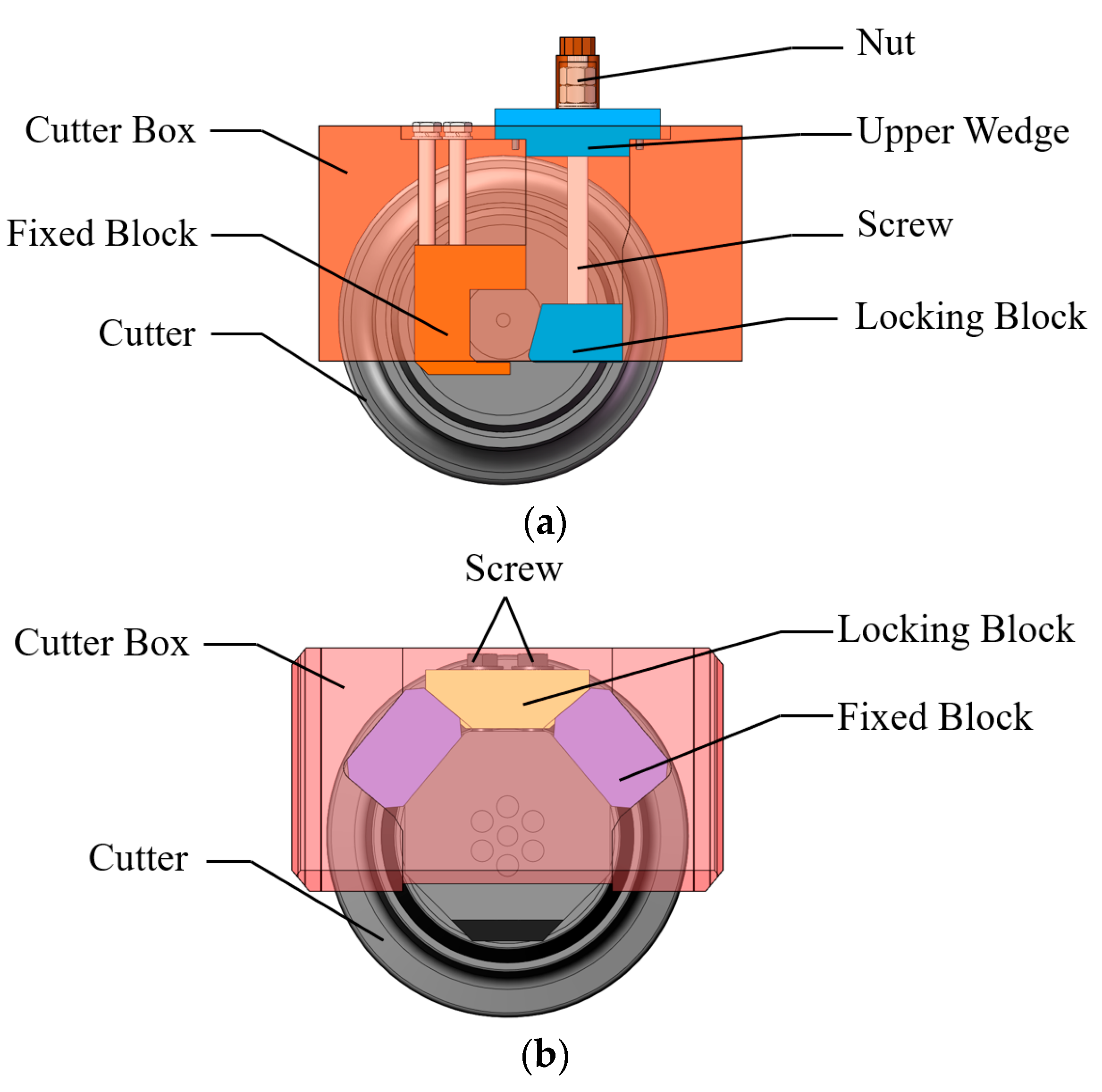
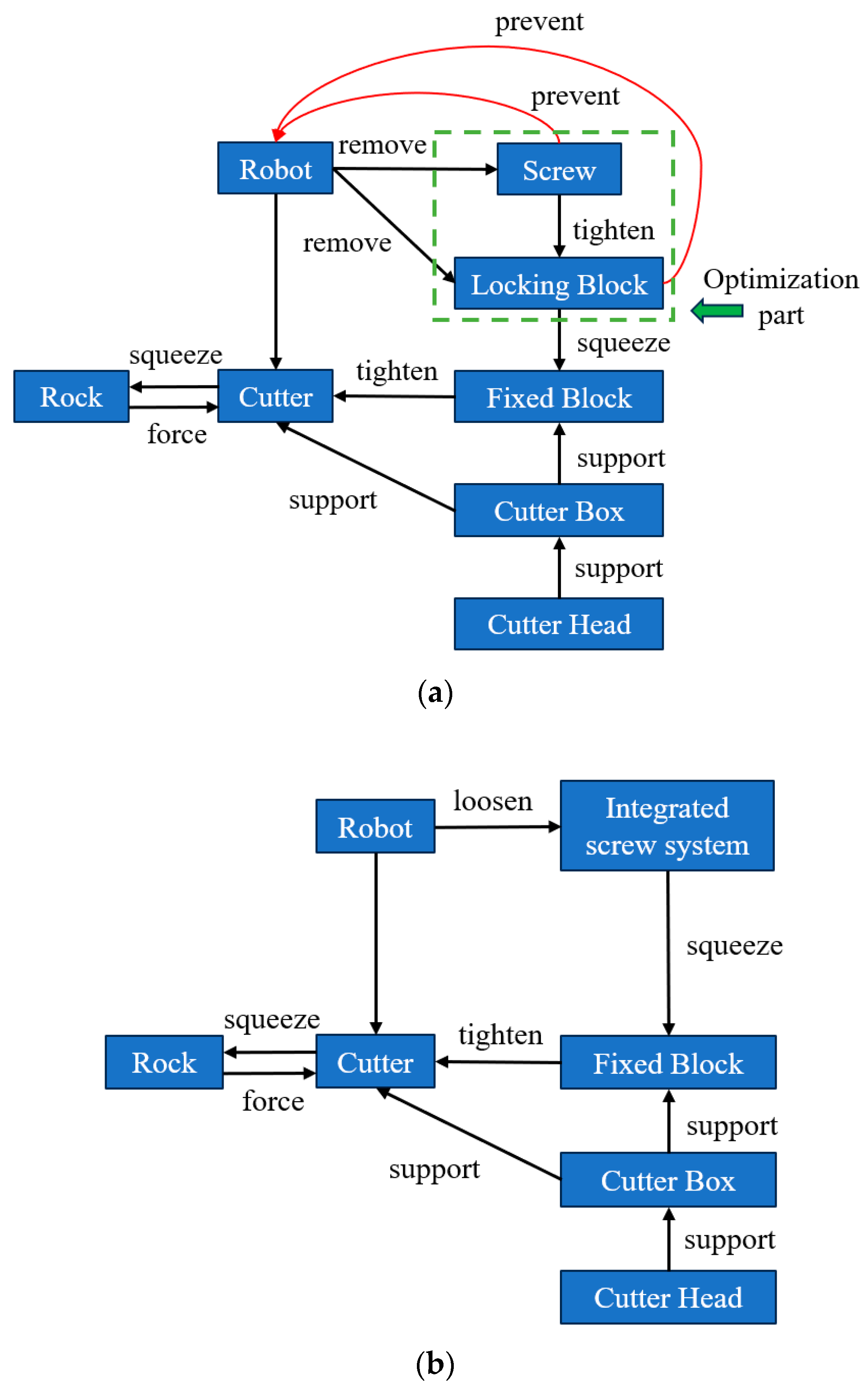
2.1. Structural Analysis of the Traditional Cutter System

The structural form of the traditional cutter system can usually be divided into double-wedge-type cutter systems, back-mounted cutter systems, and upper-and-lower- wedge-type cutter systems. As shown in Figure 1a, this paper takes the common upper-and-lower-wedge-type cutter system as an example, which usually consists of double nuts, screws, an upper wedge, a locking block, a fixed block, a cutter box and other parts. The disassembly process is as follows: firstly, unscrew the nut set and the double nut, then remove the upper wedge, and finally use a tool to eject the locking block to remove the cutter. This TCS has the advantages of small size and good fastening performance, but the cutter-change process is cumbersome, and it is difficult to design an automated disassembly tool for the existing cutter structure. Figure 1b is a double-wedge block-type cutter system, which usually consists of bolts, locking blocks, fixed blocks, a cutter box and other parts. The disassembly process is as follows: firstly, take out the four bolts, then disassemble the two locking blocks on both sides, then disassemble the four fixing blocks for fixing the cutter shaft and finally pull the cutter out of the cutter box to complete the disassembly. This cutter system also has excellent fastening performance, but the larger cutter shaft of the cutter results in a larger cutter weight, less space to change the cutter and less interchangeability with other cutter systems. Therefore, this type of cutter is not common and has been phased out. In the following, only the most common upper-and-lower-wedge-type cutter systems are evaluated.

2.2. TRIZ-Based Trimming Method for Design of the Cutter System

Aiming at the above problems of traditional cutter systems, this paper is based on the TRIZ theory’s trimming method to simplify the disassembly steps of the cutter system. Trimming is one of the means used to improve the performance of the system in TRIZ innovation theory, which relies on the functional analysis of components to obtain the relationship between components and removes or replaces the harmful parts of components [17]. As shown in Figure 2a, the presence of dispersed parts, such as the screw and locking block, greatly restricts the disassembly process of the robot, so the screw and locking block need to be trimmed away. However, removing the two will make the cutter system lose its locking function, so this paper designed different types of integrated bolt systems to realize the locking function of the cutter based on the TCS in Figure 1. The improved functional model is shown in Figure 2b, and the replacement of the cutter can be accomplished by only three processes: rotating the screw, grasping the cutter and extracting the cutter.

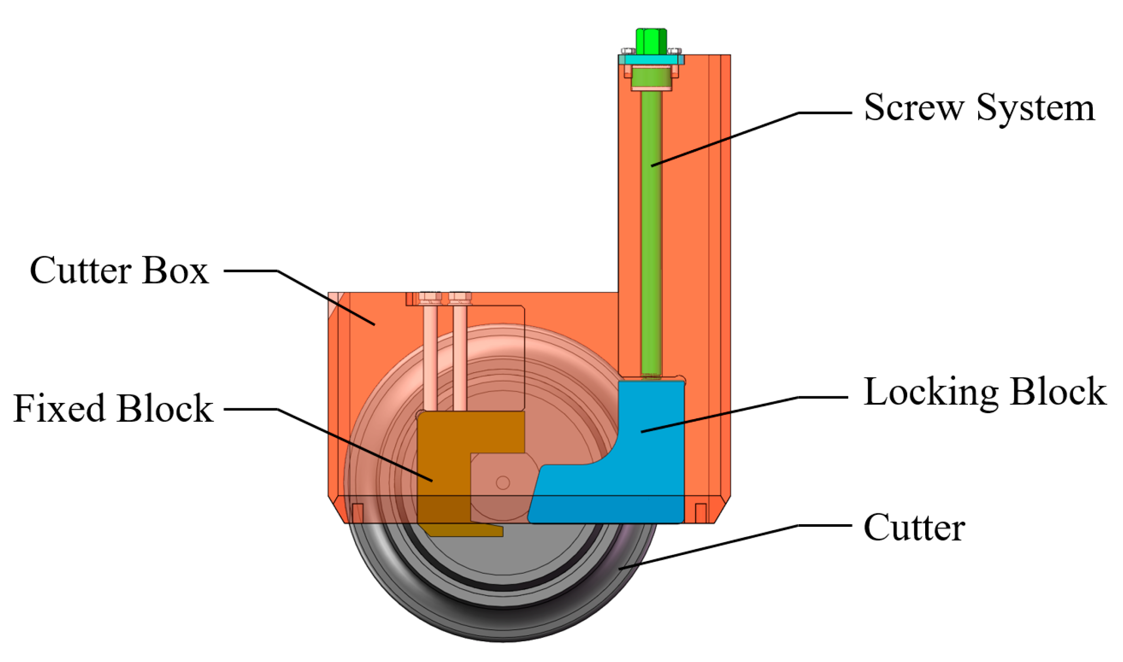
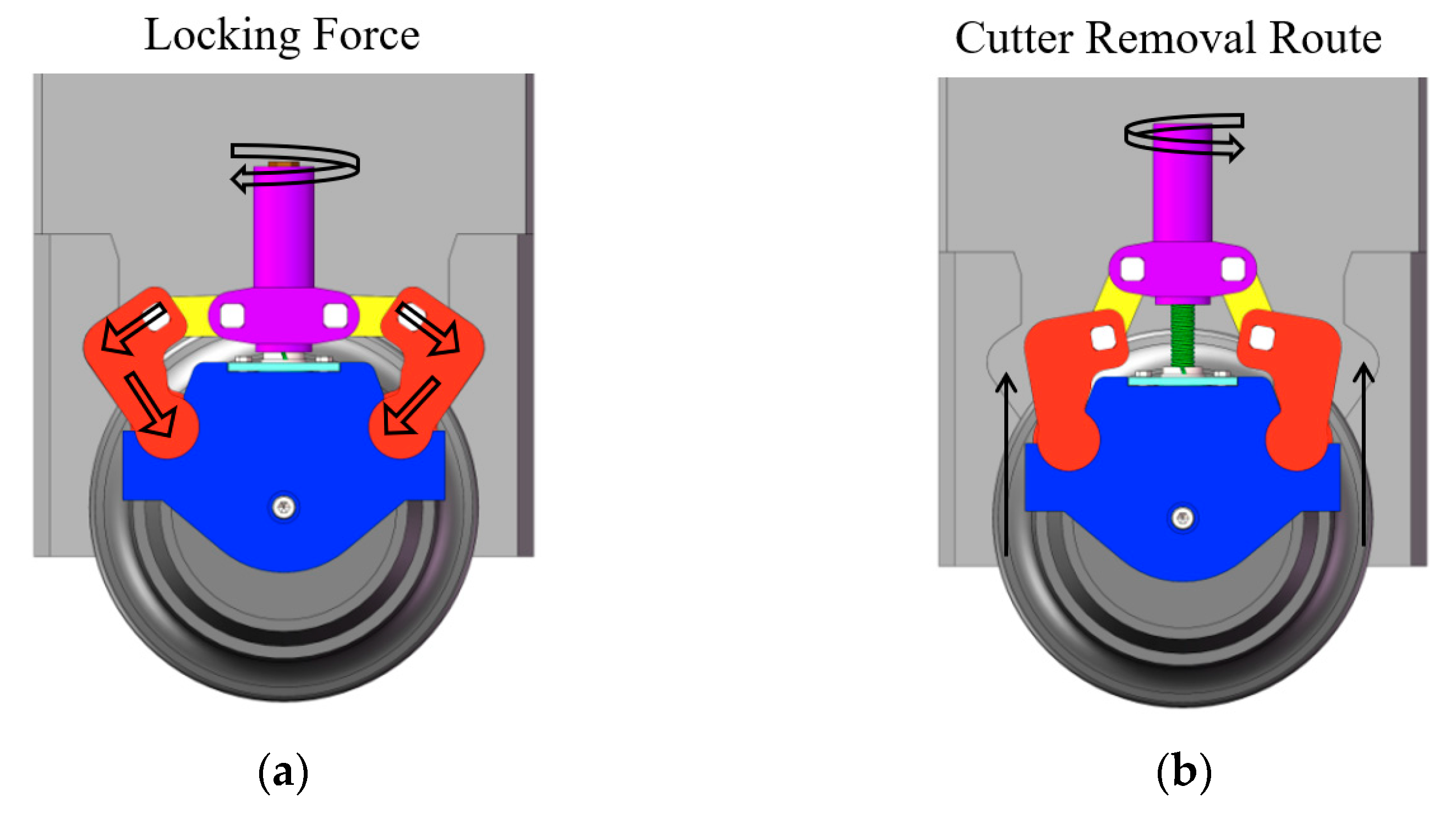
2.3. Eccentric Integrated Cutter System

Figure 3 shows the eccentric integrated cutter system (EICS), which evolved from traditional cutter systems of the upper and lower wedge type. Compared to traditional cutter systems, the EICS maintains the fixed block structure of the left half of the cutter system and integrates the right half of the cutter system, which requires frequent disassembly. While inheriting the good fastening performance of traditional cutter systems, the disassembly process has been simplified from 10 to 3 steps.
Its main working principle is shown in Figure 4. When removing the cutter, the screw rotates counterclockwise, driving the moving wedge to perform the movement away from the cutter, thus loosening the cutter, and then the end-effector grasps the cutter and removes the cutter according to the predetermined path; when fastening the cutter, the end-effector firstly places the cutter in the specified position. When tightening the cutter, the end-effector firstly places the cutter in the specified position, and then the screw rotates clockwise to drive the moving wedge to make a movement close to the cutter, so as to tighten the cutter.

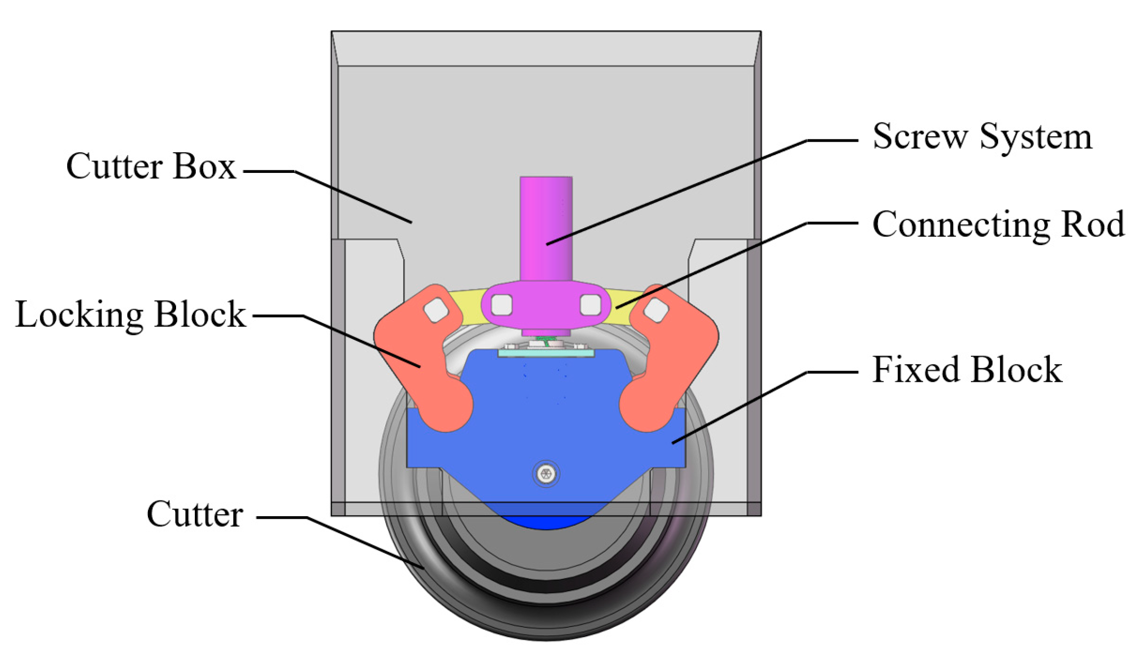
2.4. Center Integrated Cutter System

Figure 5 shows the center integrated cutter system (CICS), which is essentially a six-bar single-degree-of-freedom mechanism evolved based on topology theory. The blue part is the fixing mechanism, which is mainly responsible for fixing the cutter shaft. The red part is the locking mechanism, which can be rotated around the center of the arc and articulated with the fixed block through the groove below.
Its main working principle is shown in Figure 6. When removing the cutter, the screw in the purple part of the top rotates counterclockwise and drives the locking block to rotate around the center of its own arc through the yellow linkage mechanism to loosen the cutter, and then the end-effector grabs the whole mechanism and the cutter. Then, the end-effector grabs the whole mechanism and the cutter. The CICS also has the advantage of simple dismantling steps; only three procedures can realize the cutter dismantling and installation tasks.

3. Evaluation and Decision Making for the Integrated Cutter System

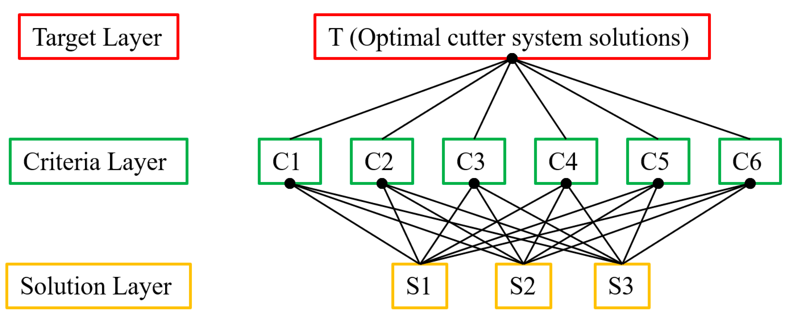
3.1. Establishment of the AHP Evaluation System

In the previous section, three types of cutter systems, including traditional cutter systems, were introduced in this paper. In order to objectively evaluate the best cutter system solution design out of these three solutions, this paper analyzed the indicators of the cutter system based on the AHP. A comprehensive score table was established so that the performance gaps between each cutter system could be visualized. As shown in Figure 7, the key to decision making for the cutter program through AHP lies in the establishment of an evaluation index system, i.e., clarifying the target layer, the criterion layer, the program layer and the relative weights among the criterion factors. For the target layer, the ultimate goal is to select the best cutter system. For the solution layer, it consists mainly of three different cutter systems. As for the criterion layer, this paper selected static strength, the disassembly process, gripping size, gripping quality, three-dimensional size and preload force as the criterion factors, and these indexes will be analyzed one by one in the following.
(1) Static strength analysis
Shield machine operation relies on the rolling cutter to cut and squeeze the rock to realize the tunneling function. During this period, the cutter system will be subjected to large impact loads and vibration, and it needs to ensure strong rigidity and resistance to deformation. In order to check whether the cutter structure meets the strength design requirements under severe working conditions, static strength analysis is an indispensable step.
(2) Grab size and three-dimensional dimensions
The internal space of the shield machine is shown in Figure 8. The cutter-changing robot is placed in a human cabin with a diameter of about 2 m. The length of its activity space is about 7 m. The length of its working area reaches 7.5 m, and the narrowest point in the width direction is about 0.8 m. The ratio of the cutter-changing robot in the horizon-tal and vertical directions is <1:9, which is a narrow and long characteristic. Therefore, in the process of the robot taking out the cutter, there are certain requirements on the size of the mechanism it grabs.
(3) Grab quality
Compared to manual cutter changing, the quality of the cutter system’s grip will have a direct impact on the design of the robot. If the gripping quality increases, the robot will require more output power from the end gripping mechanism, the displacement mechanism, etc., resulting in an increase in the design size of the corresponding equipment in the small space of the shield machine. In addition, as the end load of the robot increases, its dynamics and trajectory planning conditions become more difficult. Therefore, the addition of extra gripping mass should be avoided as much as possible during the design of an integrated cutter system.
(4) Disassembly process
Since the TCS has the problem of cumbersome disassembly steps, the main purpose of the present design of the integrated cutter system is to simplify the disassembly steps of the TCS and to lay the foundation for the realization of mechanized automatic disassembly. Therefore, the disassembly process of the cutter system is an important index to measure its performance.
(5) Preload force
In threaded connections, it is common to apply a preload force to enhance the reliability and loosening resistance of the connection. As the cutter keeps cutting soil and rock during the tunneling process of the shield machine, the cutter structure is subjected to continuous impact and vibration, which very easily produces loosening phenomena. Therefore, the preload force of the screw in the cutter system and the loosening prevention ability of the whole system are important evaluation indexes.

3.2. Analysis of the AHP Evaluation System

3.2.1. Static Strength Analysis

In this paper, the standard loads commonly used in cutter testing [18] were selected to carry out a static analysis of three cutter systems. The standard loads are shown in Figure 9a, where the normal load, lateral load and rolling load are 315 kN, 47.25 kN and 31.5 kN. In this paper, the finite element method (FEM) was used in the static analysis module of the Ansys Workbench to carry out the static analysis of the three cutter systems. In the static analysis of this paper, the material of the part is selected as Q345. The constraints are set on both sides of the cutter box. The load conditions are shown in Figure 9a. The static analysis of the three cutter systems is shown in Figure 9. It can be observed that the maximum equivalent stress of the EICS in Figure 9b occurs in the L-block, with a maximum value of about 78.9 MPa. The maximum equivalent stress of the TCS in Figure 9c occurs in the fixed block, with a maximum value of about 88.8 MPa. The maximum equivalent stress of the CICS in Figure 9d occurs at the connection between the connecting rod and the screw bushing, with a maximum value of about 50.6 MPa. The results show that all three cutter systems have good mechanical properties.

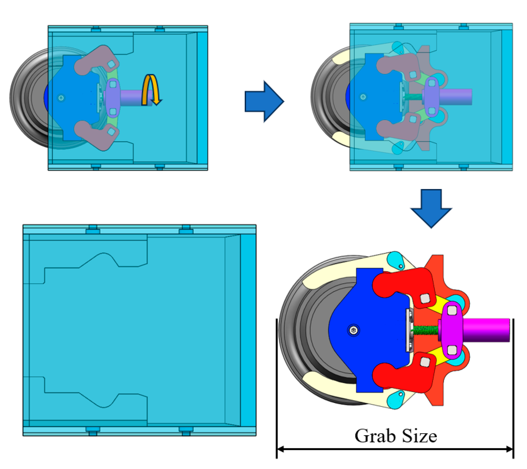
3.2.2. Grab Size and Three-Dimensional Dimensions

In the case of the CICS, for example, when the cutter is removed in the last step, the end-effector is required to remove the entire integrated cutter structure in its entirety. At this time, the gripping size, shown in Figure 10—the distance from the top of the screw to the cutter blade circle—is about 744 mm, while for the EICS and TCS, when removing the cutter, they only need to grip the cutter body and do not need to consider the rest of the part. Therefore, the gripping size of these two can be considered as the size of the cutter, which is about 483 mm.
In addition, it is difficult to change the existing cutter structure because the reserved position and the size of each cutter in the shield cutter plate have been determined based on the TCS. Therefore, the three-dimensional dimensions of the integrated cutter system should not exceed the three-dimensional dimensions of the TCS. Based on the shape of the TCS box, this paper constructed two kinds of 3D models of cutter systems in SolidWorks. And the SolidWorks MBD module was directly used for the dimensions in the 3D model. The dimensions of the housings are shown in Figure 11, both of which were 930 mm × 680 mm × 496 mm.

3.2.3. Grab Quality

The cutter-change process for all three cutter systems is detailed in Section 2 of this paper. For the TCS and EICS, only a single cutter needs to be gripped when the robot completes the disassembly process. Therefore, the gripping mass for both of them is the same, about 196 kg, while for the CICS, when the robot rotates the bolt to relax it, the whole mechanism is still fixed to the cutter and they need to be removed together. Finally, the gripping mass of the CICS was calculated to be approximately 330 kg using the mass evaluation module in SolidWorks.

3.2.4. Disassembly Process

In the previous section of this paper, the structural composition and working principle of the three cutter systems were described in detail. The disassembly process of TCS is divided into 10 steps and it requires the disassembly of 13 parts. The disassembly process of CICS is the same as that of EICS and the process can be roughly divided into 3 steps. The first step is to rotate the topmost screw to return the locking mechanism to the relaxed state. Then, the robot’s end-effector is driven to grab the cutter. Finally, the cutter is removed according to a predetermined route. The number of parts involved in the disassembly process is 13 for the CICS, while the EICS is simpler, involving only 5 parts (Table 1).

3.2.5. Preload Force

The preload force of the screw is mainly determined by the grade and size of the bolt. In this paper, the three kinds of cutter system all used bolts with a strength grade of 10.9, and the nominal diameter of the bolts was the same, so the preload force was 275 kN.

3.3. Results of the AHP Evaluation System

In summary, this paper analyzed the six evaluation indexes of the integrated cutter system one by one and obtained the evaluation and analysis table shown in Table 2. In the table, C1 is the disassembly process, C2 is the gripping size, C3 is the three-dimensional size, C4 is the static strength, C5 is the gripping quality and C6 is the preload force. In addition, in order to visualize the gap between the cutter systems, the data in the table should be normalized. The principle of normalized data processing is as follows: take the best value in each column as the base and process the rest of the data. In the end, the best cutter system is the one with the highest overall score.
In the comparative evaluation of the three cutter systems, the weights occupied by each criterion factor needed to be measured as well. The Dalian University of Technology proposed a discriminant matrix [19], as shown in Equation (1). Through a two-phase comparison of the criterion factors, a matrix that can objectively reflect the importance of the criterion factors is finally derived.
T = 1 1 / 2 3 2 2 3 2 1 5 3 3 5 1 / 3 1 / 5 1 1 / 2 1 / 2 2 1 / 2 1 / 3 2 1 1 2 1 / 2 1 / 3 2 1 1 2 1 / 3 1 / 5 1 / 2 1 / 2 1 / 2 1
The eigenvector corresponding to the maximum eigenvalue can be obtained by calculating Equation (1), as shown in Equation (2).
w = 3.550 6.054 1.269 2.045 2.045 1 T
Equation (2) is normalized to obtain Equation (3), which can be used as the weight ratio of each criterion factor in the criterion layer.
w ^ = 0.2224 0.3793 0.0795 0.1281 0.1281 0.0626 T
This is then weighted by Equation (3), with the results after normalizing each criterion factor in Table 2 shown in Equation (4).
S = w ^ 1 c 1 + w ^ 2 c 2 + w ^ 3 c 3 + w ^ 4 c 4 + w ^ 5 c 5 + w ^ 6 c 6
The final composite scores of the three cutter schemes were obtained, as shown in Table 3. Table 3 shows that the TCS has the lowest score of 0.79. CICS has a score of 0.81, which is slightly better than that of the TCS, but due to the fact that when removing the cutter, it is necessary to take out the cutter together with the locking device, there is a big disadvantage in the quality of the gripping as well as the size of the gripping, and the EICS has the highest overall score of 0.95. Compared with the other two, it is only slightly inferior to the CICS in terms of static strength, but it is still superior to the TCS, so this paper chose the EICS as the best cutter system solution.

4. Verification of the Anti-Loosening Performance of the Integrated Cutter System

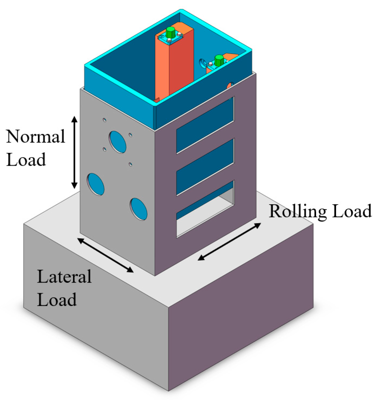
4.1. Experimental Design

This paper mainly refers to the accelerated vibration experimental method, aiming at evaluating the anti-loosening performance of a cutter by simulating its working condition in a vibration environment. Firstly, referring to the fastener experiment method in GJB715.3A-2002 [20], the preload size of the integrated cutter system was measured by strain gauges, and the curve of the preload of the cutter system over time was obtained. Then, its residual preload force after vibration was used as a reference to evaluate the anti-loosening performance of the integrated cutter system scheme.
Through reviewing the relevant literature [21,22,23] and the field data of some shield construction sections, it could be learned that the amplitude and frequency of the vibration of the cutter system are related to the tunneling parameters of the shield machine, such as the cutter rotational speed, penetration and propulsion, and the geologic conditions of the construction section. With the increase in cutter speed, penetration, propulsion force and rock hardness, the vibration of the cutter becomes worse. In general, in shield construction, the cutter faces soft ground or soil–rock composite layers, and the hardness of the rock layers is low, resulting in more moderate vibration. The vibration frequency is mainly concentrated in the low-frequency range of 0~10 Hz, and the vibration acceleration is mainly concentrated in the range of ±3 g [24]. Therefore, a vibration peak acceleration of 2.5 g and a vibration frequency of 7 Hz were finally selected for the working conditions of this experiment.

4.2. Experimental Procedure

This experiment mainly involved the experimental equipment shown in Figure 12. Figure 12a shows a resistance strain gauge, which was responsible for measuring the strain change in the screw. Figure 12b is the strain collector, which was responsible for receiving and recording the strain information output from the strain gauges. The strain collector selects INV3062A from the China Orient Institute of Noise & Vibration (Beijing, China), and its main technical indexes are as follows: sampling rate: 0.5 Hz~204.8 kHz adjustable; AD precision: 24-bit Δ-sigma mode; number of analog input channels: 16; dynamic range: 120 dB. Figure 12c shows a constant torque wrench, which can apply rated torque on the screw. Figure 12d shows the equal-scale eccentric integrated cutter prototype. Figure 12e shows the electrodynamic vibration test system, model IPA180L/H1859A. Its main technical indexes are as follows: rated sinusoidal thrust: 16,000 kgf; frequency range: 2–2000 Hz; rated displacement: 51 mm; rated speed: 1.8 m/s; rated acceleration: 981 m/s2; maximum load: 1600 kg.
Firstly, the strain gauges were pasted and the strain collector was connected. Its pasting position is shown in Figure 13, where three strain gauges were pasted on both sides of the screw along the axis direction. Among them, S1, S2 and S3 represent the left-side screw, and S4, S5 and S6 represent the right-side screw. Then, by consulting the bolt preload comparison table, it can be seen that a torque of 1650 N·m should be applied to the M30 bolts. Then, the constant torque wrench shown in the figure was used to tighten the experimental sample by applying a torque of 1650 N·m and observe whether the strain gauges worked properly. After confirming that the strain gauges had not failed, the test specimen could be assembled on the vibration test bench and the vibration test could be started. Finally, the vibration test was started with the selected working conditions, and changes in strain values were recorded by sampling regularly. The vibration direction is shown in Figure 14: 8 h of continuous vibration in the normal load direction and 3 h of continuous vibration in the lateral load and rolling load direction.

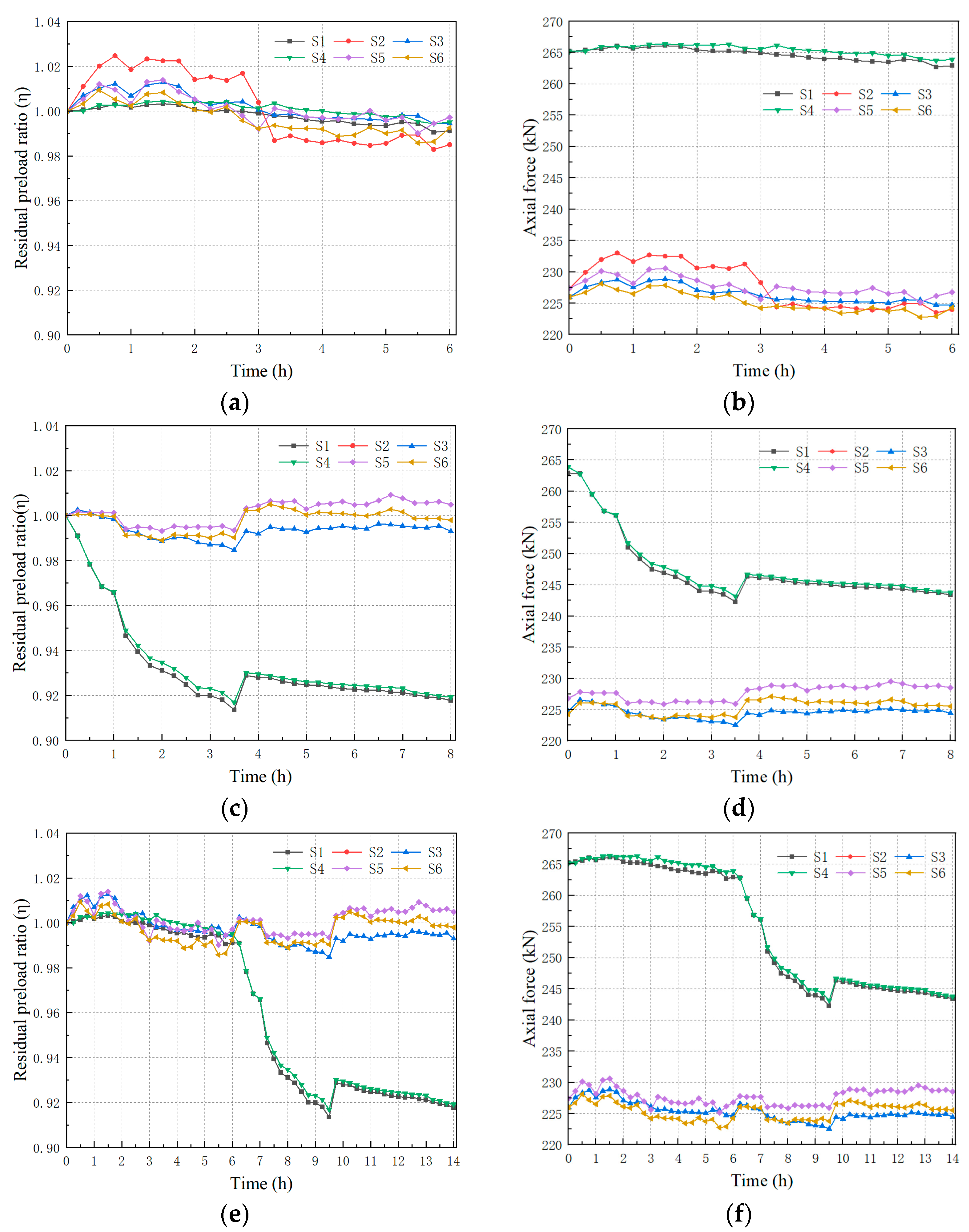
4.3. Experimental Results and Analysis

After the end of the vibration test, a strain value with time change curve could be obtained. This paper found that the two sides along the axial paste of the three strain gauges of the alignment of the change trend were the same, but there were some differences in the numerical values. For this reason, this paper carried out a detailed analysis of the force on the bolt and found that the bolt does not only bear the axial load. The force analysis of the whole locking system is shown in Figure 15. Firstly, regarding the locking block, it will be subjected to the extrusion reaction force (F1) from the shaft of the cutter and the extrusion reaction force (F2) from the box, as well as the upward tension force (F3) of the bolt. F1 can be further decomposed into F1x in the horizontal direction and F1y in the vertical direction, which form moments with F2 and F3, respectively. At this point, in order to balance the resulting torque, the screw will generate force FM on the locking block, and, accordingly, the screw will be subject to the reaction FM’ of the locking block, resulting in the bending of both sides of the screw in the direction close to the cutter, which will lead to the strain gauges affixed to S1 and S4 being more pronounced in comparison with the other points.
Based on the above analysis, it can be seen that FM’ has an effect on the measurement results of the strain gauges, resulting in the inability to perform a simple averaging of the strain gauges for the same screw. Therefore, this evaluation model was simplified in this paper by comparing the data of six strain gauges in vibration tests with their respective initial values as a way to reduce the influence of FM’ on different strain gauges. Based on the simplified model, each strain gauge can be regarded as a uniaxial loaded state. It can be processed by Equations (5) and (6) to obtain the curve of the preload force with time for the integrated cutter system, where E is the modulus of elasticity of the material, S is the cross-sectional area of the screw and F is the preload force of the screw.
ε = σ E
σ = F S
In addition, in order to facilitate the analysis of the influence of the vibration direction and the position of the strain gauge paste on the change in the preload force, this paper carried out a normalization process. Taking the initial preload force as a benchmark, the ratio of the residual preload force to the initial force at each moment was calculated, as shown in Equation (7), where Ft is the axial force at moment t and F0 is the initial preload force.
η = F t F 0
After the above processing, the preload variation curve of the integrated cutter sample was finally obtained, as shown in Figure 16.
The following can be seen in Figure 16:
  • The strain gauges pasted at S1 and S4 are the most sensitive to the change in strain information and start to show a significant decrease at the 6th hour of vibration. The strain gauges at the rest of the locations also show the same trend of change, first gradually decreasing to a certain degree and then stabilizing. This phenomenon is consistent with the loosening trend of the screw and the above analysis of the screw force, which indicates that the strain gauges on the screws can reflect the fastening state of the screws during vibration.
  • In the first 6 h, at the beginning of the vibration experiment, for the lateral axial load direction vibration, the residual preload ratio and preload curve did not show significant changes. This indicates that the integrated cutter system is not sensitive to vibration in these two directions. During the 8 h of vibration in the normal load direction, there is a significant drop in the preload curve. After 10 h of vibration, the preload gradually stabilized, and the residual preload ratio decreased to about 92%. The preload of the S1 and S4 curves decreased from 265 kN to 240 kN, and the preload of the S3, S5 and S6 curves did not show any obvious decrease. The strain gauges at S2 failed after 6 h of vibration.
In summary, the integrated cutter samples were stabilized at more than 90% of the residual preload ratio after 14 h of continuous vibration, and the loss of preload was within the acceptable range. Referring to the ISO 16130-2015 standard [25] and combining this with on-site inspection, it can be judged that the integrated cutter undergoes no loosening and has good locking performance.

5. Conclusions

In this paper, a new eccentric integrated cutter system is proposed, which has excellent comprehensive qualities in terms of its disassembly process, static strength and gripping quality, as well as good fastening performance. The main research work includes the following three aspects:
  • Although traditional cutter systems are cumbersome to disassemble, their mature structural designs still have the advantages of small size and good fastening performance. This paper firstly optimizes the design based on the mechanism of traditional cutter systems, and while retaining their left-side fixed structure, the locking structure on the right side is designed as a whole structure that can be linked, which finally forms an eccentric integrated cutter system. Finally, this paper introduces a center integrated cutter system based on the evolution of a six-bar single-degree-of-freedom mechanism.
  • In this paper, six evaluation indexes, namely, static strength, the disassembly process, gripping size, gripping quality, three-dimensional size and preload force, are selected to establish the evaluation system of the integrated cutter system through the analytic hierarchy process. And the above three cutter systems are evaluated one by one for comparison, and it is concluded that the two integrated cutter systems are superior to the traditional cutter systems. However, the center integrated cutter system is slightly inferior to the eccentric integrated cutter system in terms of gripping quality as well as gripping dimensions.
  • In order to verify the anti-loosening performance of the eccentric integrated cutter system, this paper designs a vibration experiment based on the fastener experiment method in GJB715.3A-2002. The experimental results show that the integrated cutter system is most sensitive to vibration in the direction of normal load. The preload force gradually stabilizes 10 h after the start of the vibration, the residual preload ratio value decreases to 92% at its lowest, the preload force decreases from 265 kN to 240 kN and the residual preload ratio value stabilizes at more than 90%, which shows good locking performance.
Regarding the research on the eccentric integrated cutter system, although some results have been achieved, there are still many shortcomings. In the future, a dynamic model could be established to explore the dynamic characteristics of the new cutter system. Comparison experiments with traditional cutter samples could also be carried out to further examine the fastening performance of the new cutter samples.

Author Contributions

Funding acquisition, Y.M.; Conceptualization, S.L.; Methodology, J.H.; Writing—original draft preparation, K.H.; Writing—review and editing, S.L.; Project administration, H.W.; Data curation, H.C. All authors have read and agreed to the published version of the manuscript.

Funding

This work was supported by “Technology R&D Project of China Railway Construction Co., Ltd: 2021-B05”, and “Technology R&D Project of China Railway 14th Bureau Group Co., Ltd: 913700001630559891202110”.

Institutional Review Board Statement

Not applicable.

Informed Consent Statement

Not applicable.

Data Availability Statement

The data presented in this study are available on request from the authors.

Conflicts of Interest

The authors declare that they have no known competing financial interests or personal relationships that could have appeared to influence the work reported in this paper. Sijin Liu, Huawei Wang and Yuyang Ma are employees of China Railway 14th Bureau Group Co., Ltd.; Yuyang Ma is employee of China Railway Construction Co., Ltd. China Railway 14th Bureau Group Co., Ltd. and China Railway Construction Co., Ltd. provided funding and technical support for the work. The funder had no role in the design of the study; in the collection, analysis, or interpretation of data, in the writing of the manuscript, or in the decision to publish the results.

References

  1. Frough, O.; Khetwal, A.; Rostami, J. Predicting TBM utilization factor using discrete event simulation models. Tunn. Undergr. Space Technol. 2019, 87, 91–99. [Google Scholar] [CrossRef]
  2. Delisio, A.; Zhao, J. A new model for TBM performance prediction in blocky rock conditions. Tunn. Undergr. Space Technol. 2014, 43, 440–452. [Google Scholar] [CrossRef]
  3. Herrenknecht, E.H.M.; Bäppler, K. Compressed air work with tunnel boring machines. In Proceedings of the 33rd ITA-AITES World Tunnel Congress, Prague, Czech Republic, 5–10 May 2007; pp. 1175–1181. [Google Scholar]
  4. Falk, C. Pre-investigation of the subsoil developments in construction of the 4th Elbe Tunnel Tube. Tunn. Undergr. Space Technol. 1998, 13, 111–119. [Google Scholar] [CrossRef]
  5. Copur, H.; Cinar, M.; Okten, G.; Bilgin, N. A case study on the methane explosion in the excavation chamber of an EPB-TBM and lessons learnt including some recent accidents. Tunn. Undergr. Space Technol. 2012, 27, 159–167. [Google Scholar] [CrossRef]
  6. Chen, H.; Li, H.; Huo, J.Z.; Yang, B.W.; Yang, F. Assembly Deviation Analysis of New Integrated TBM Disc Cutter and Design of the Supporting Cutter-Changing Robot End-Effector. Appl. Sci. 2022, 12, 9549. [Google Scholar] [CrossRef]
  7. Mansard, N.; Khatib, O.; Kheddar, A. A Unified Approach to Integrate Unilateral Constraints in the Stack of Tasks. IEEE Trans. Robot. 2009, 25, 670–685. [Google Scholar] [CrossRef]
  8. Camus, T.; Moubarak, S. Maintenance Robotics in TBM Tunnelling. In Proceedings of the 32nd International Symposium on Automation and Robotics in Construction and Mining (ISARC 2015), Oulu, Finland, 15–18 June 2015. [Google Scholar]
  9. Bogue, R. Snake robots A review of research, products and applications. Ind. Robot.-Int. J. 2014, 41, 253–258. [Google Scholar] [CrossRef]
  10. Simi, A.; Manacorda, G.; IEEE. The NeTTUN Project: Design of a GPR Antenna for a TBM. In Proceedings of the 16th International Conference on Ground Penetrating Radar (GPR), Hong Kong Polytechn Univ, Dept Land Surveying & Geo Informat, Hong Kong, China, 13–16 June 2016. [Google Scholar]
  11. Du, L.; Yuan, J.J.; Bao, S.; Guan, R.M.; Wan, W.W. Robotic replacement for disc cutters in tunnel boring machines. Autom. Constr. 2022, 140, 104369. [Google Scholar] [CrossRef]
  12. Yuan, J.J.; Guan, R.M.; Guo, D.Z.; Lai, J.X.; Du, L.; IEEE. Discussion on the Robotic Approach of Disc Cutter Replacement for Shield Machine. In Proceedings of the IEEE International Conference on Real-time Computing and Robotics (IEEE-RCAR), Asahikawa, Japan, 28–29 September 2020; pp. 204–209. [Google Scholar]
  13. Yang, F.; Lan, T.; Huo, J.Z.; Shi, Y.T.; Chen, H. Design of a New TBM Integrated Cutter System Based on Analysis of Mechanical Properties and Dynamic Characteristics. Appl. Sci. 2022, 12, 2332. [Google Scholar] [CrossRef]
  14. Xia, Y.M.; Yang, M.; Ji, Z.Y.; Jia, L.H.; Zhou, Z.X.; Wu, D. Design and dimension optimization of cutter disassembly mechanism for shield tunneling machine. J. Mech. Sci. Technol. 2021, 35, 3005–3018. [Google Scholar] [CrossRef]
  15. Bhattacharya, A.; Sen, A.; Das, S. An investigation on the anti-loosening characteristics of threaded fasteners under vibratory conditions. Mech. Mach. Theory 2010, 45, 1215–1225. [Google Scholar] [CrossRef]
  16. Wang, X.Y.; Liu, J.Q.; Guo, W. A Case-based Reasoning Combined with AHP wighting for Cutter Conceptual Configuration Prediction Model. In Proceedings of the 2nd International Conference on Advances in Materials and Manufacturing Processes (ICAMMP 2011), Guillin, China, 16–18 December 2011; pp. 1919–1924. [Google Scholar]
  17. Zhang, E.H.; Gao, C.Q.; Yang, B.; Su, H.H. The Conceptual Design of Exercise Washing Machine Based on Trimming. In Proceedings of the 2nd International Conference on Advanced Design and Manufacturing Engineering (ADME 2012), Taiyuan, China, 16–18 August 2012; pp. 561–565. [Google Scholar]
  18. Huo, J.Z.; Zhang, H.D.; Xu, Z.H.; Liu, H.X.; Dong, J.H. Coupling dynamic characteristics of tunnel boring machine cutterhead system with multi-source uncertainties. Eng. Fail. Anal. 2022, 137, 106180. [Google Scholar] [CrossRef]
  19. Meng, Z.C.; Yang, D.J.; Huo, J.Z.; Zhuo, P.Z.; Bao, Y.N. Development and Performance Evaluation of an Integrated Disc Cutter System for TBMs. Appl. Sci. 2021, 11, 644. [Google Scholar] [CrossRef]
  20. GJB715.3A-2002; Fastener Test Methods—Vibration. Commission of Science, Technology and Industry for National Defense: Beijing, China, 2002.
  21. Yang, Y.L.; Du, L.J.; Li, Q.W.; Zhao, X.B.; Ni, Z.H. Vibration prediction and analysis of the main beam of the TBM based on a multiple linear regression model. Sci. Rep. 2024, 14, 3498. [Google Scholar] [CrossRef] [PubMed]
  22. Wang, Z.Y.; Jiang, Y.S.; Shao, X.K.; Liu, C.L. On-site measurement and environmental impact of vibration caused by construction of double-shield TBM tunnel in urban subway. Sci. Rep. 2023, 13, 17689. [Google Scholar] [CrossRef] [PubMed]
  23. Huang, X.; Liu, Q.S.; Liu, H.; Zhang, P.L.; Pan, S.L.; Zhang, X.P.; Fang, J.N. Development and in-situ application of a real-time monitoring system for the interaction between TBM and surrounding rock. Tunn. Undergr. Space Technol. 2018, 81, 187–208. [Google Scholar] [CrossRef]
  24. Huo, J.Z.; Wu, H.Y.; Yang, J.; Sun, W.; Li, G.Q.; Sun, X.L. Multi-directional coupling dynamic characteristics analysis of TBM cutterhead system based on tunnelling field test. J. Mech. Sci. Technol. 2015, 29, 3043–3058. [Google Scholar] [CrossRef]
  25. ISO 16130-2015; Aerospace Series—Dynamic Testing of the Locking Behaviour of Bolted Connections under Transverse Loading Conditions (Vibration Test). ISO: Geneva, Switzerland, 2015.
Figure 1. Traditional cutter system structure: (a) upper-and-lower-wedge-type cutter system; (b) double-wedge-type cutter system.
Applsci 14 09449 g001
Figure 2. Trimming method in TRIZ: (a) harmful part clipping; (b) functional model after clipping.
Applsci 14 09449 g002
Figure 3. Eccentric integrated cutter system structure.
Applsci 14 09449 g003
Figure 4. Working principle of eccentric integrated cutter system: (a) locked state; (b) relaxed state.
Applsci 14 09449 g004
Figure 5. Center integrated cutter system structure.
Applsci 14 09449 g005
Figure 6. Working principle of center integrated cutter system: (a) locked state; (b) relaxed state.
Applsci 14 09449 g006
Figure 7. Analytic hierarchy process evaluation system.
Applsci 14 09449 g007
Figure 8. Space for cutter-changing robot.
Applsci 14 09449 g008
Figure 9. Static analysis results: (a) standard load; (b) EICS equivalent stress diagram; (c) TCS equivalent stress diagram; (d) CICS equivalent stress diagram.
Applsci 14 09449 g009
Figure 10. CICS grip size.
Applsci 14 09449 g010
Figure 11. Three-dimensional dimensions of the integrated cutter systems: (a) EICS three-dimensional dimensions; (b) CICS three-dimensional dimensions.
Applsci 14 09449 g011
Figure 12. Experimental equipment: (a) resistance strain gauge; (b) strain collector; (c) constant torque wrench; (d) equal-scale eccentric integrated cutter prototype; (e) vibration test system.
Applsci 14 09449 g012
Figure 13. Strain gauge placement.
Applsci 14 09449 g013
Figure 14. Direction of vibration.
Applsci 14 09449 g014
Figure 15. Screw force analysis.
Applsci 14 09449 g015
Figure 16. EICS preload variation curves: (a) residual preload ratio on lateral and axial loads; (b) axial forces on lateral and axial loads; (c) residual preload ratio on normal load; (d) axial forces on normal load; (e) residual preload ratio over the whole process; (f) axial forces over the whole process.
Applsci 14 09449 g016
Table 1. Disassembly process comparison table.
Type of CutterDisassembly of PartsDisassembly Process
Traditional cutter system1310
Eccentric integrated cutter system53
Positive center integrated cutter system133
Table 2. Comparative table of evaluation indicators.
Type C1C2/mmC3/mm3C4/MPaC5/kgC6/kN
TCS10483930 × 680 × 49688.8196275
CICS3744930 × 680 × 49650.6330275
EICS3483930 × 680 × 49678.9196275
Table 3. Composite score table.
TypeC1C2/mmC3/mm3C4/MPaC5/kgC6/kNScore
TCS0.301.001.000.571.001.000.79
CICS1.000.651.001.000.591.000.81
EICS1.001.001.000.641.001.000.95
Disclaimer/Publisher’s Note: The statements, opinions and data contained in all publications are solely those of the individual author(s) and contributor(s) and not of MDPI and/or the editor(s). MDPI and/or the editor(s) disclaim responsibility for any injury to people or property resulting from any ideas, methods, instructions or products referred to in the content.

