
Accelerated Creep of Asphalt Concrete at Medium Temperatures


Abstract
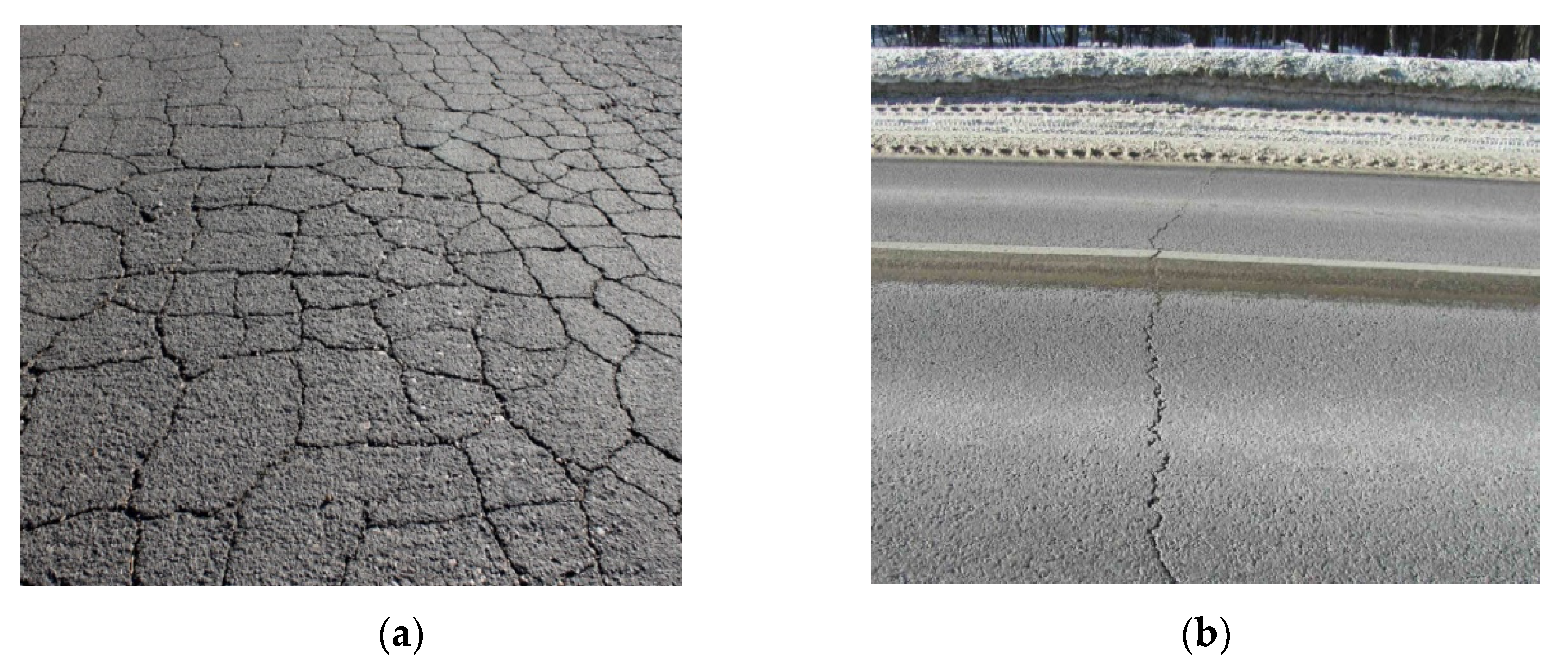
1. Introduction
2. Materials and Methods
2.1. Materials
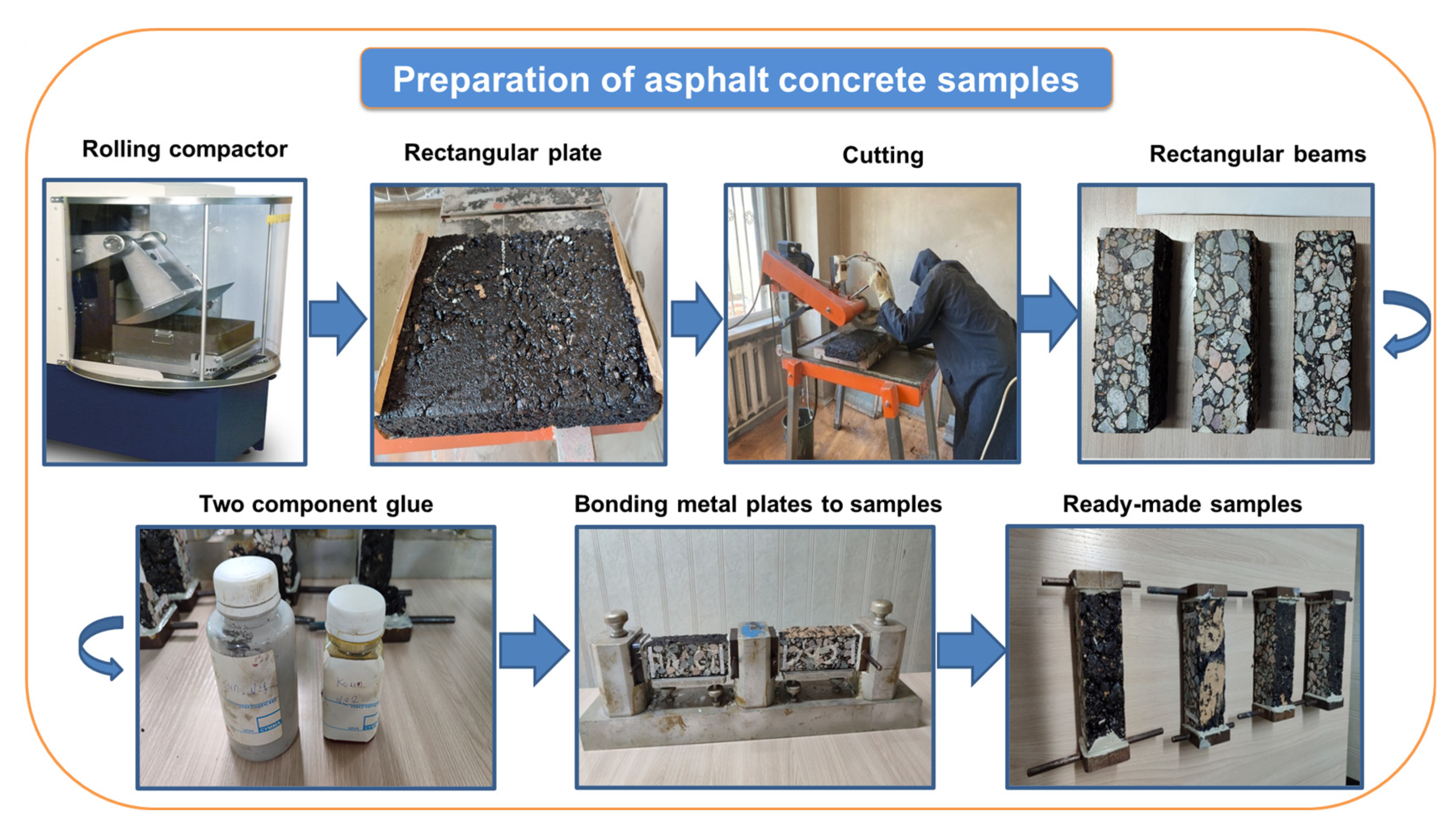
2.2. Preparation of Samples
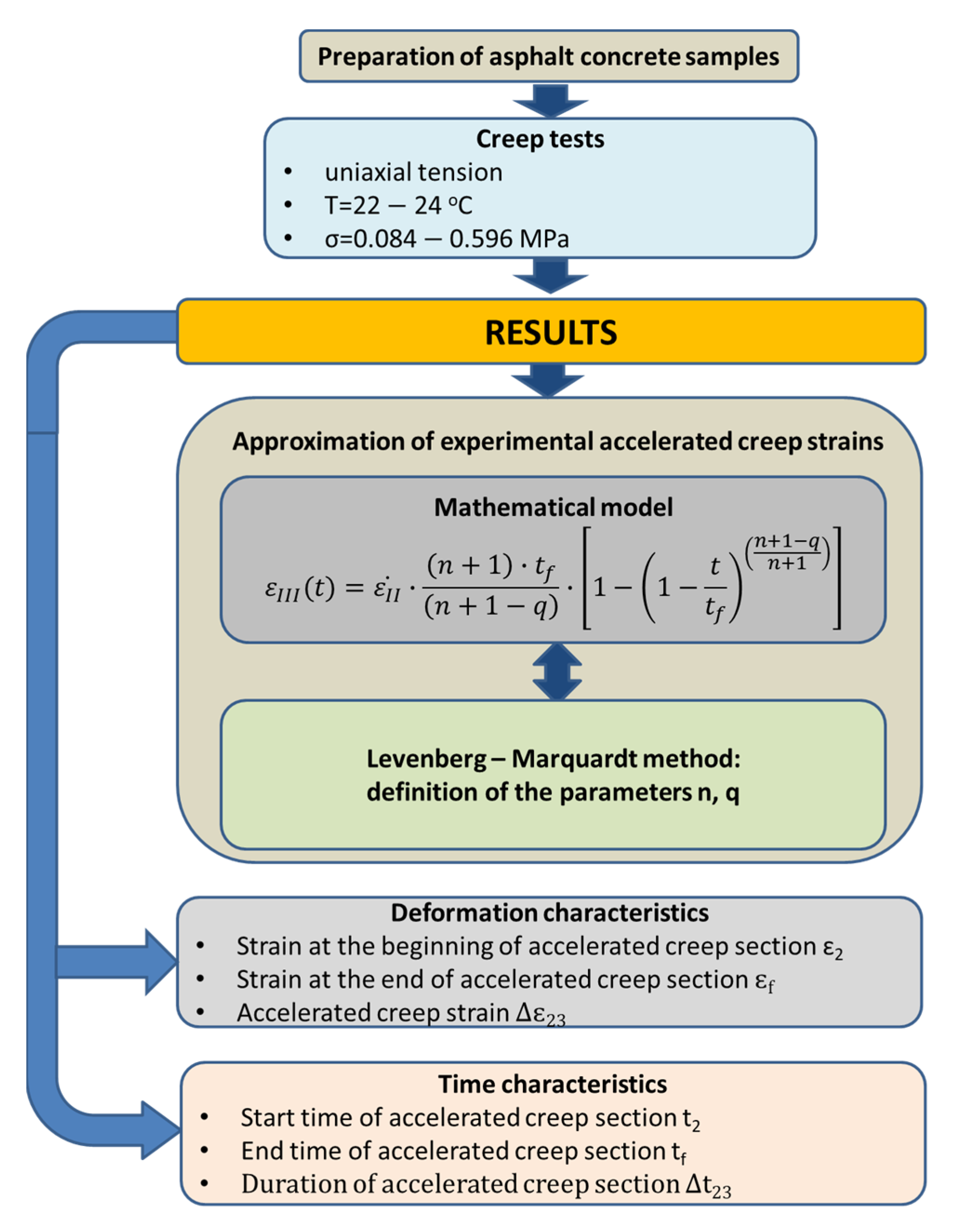
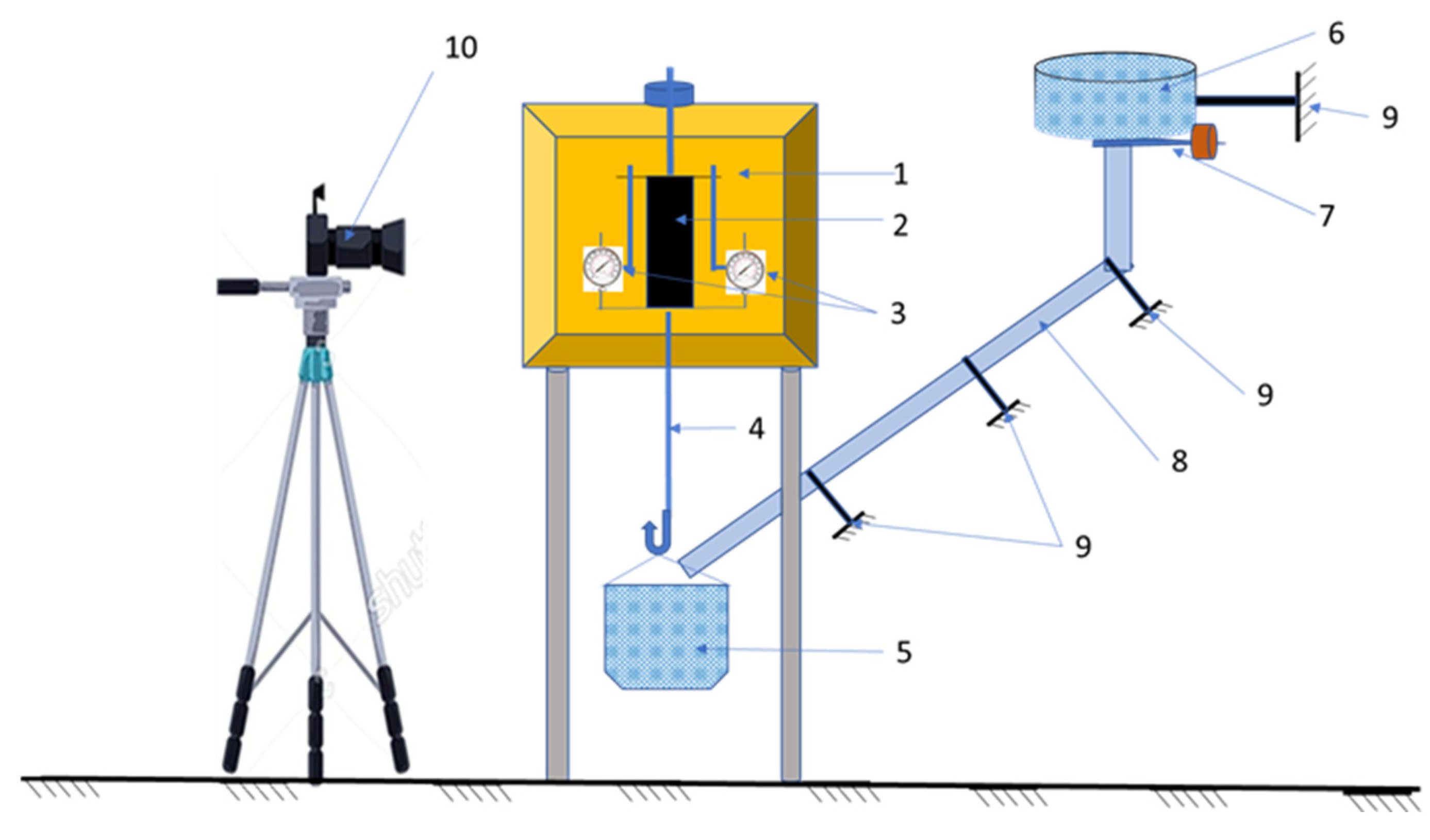
2.3. Test
3. Accelerated Creep
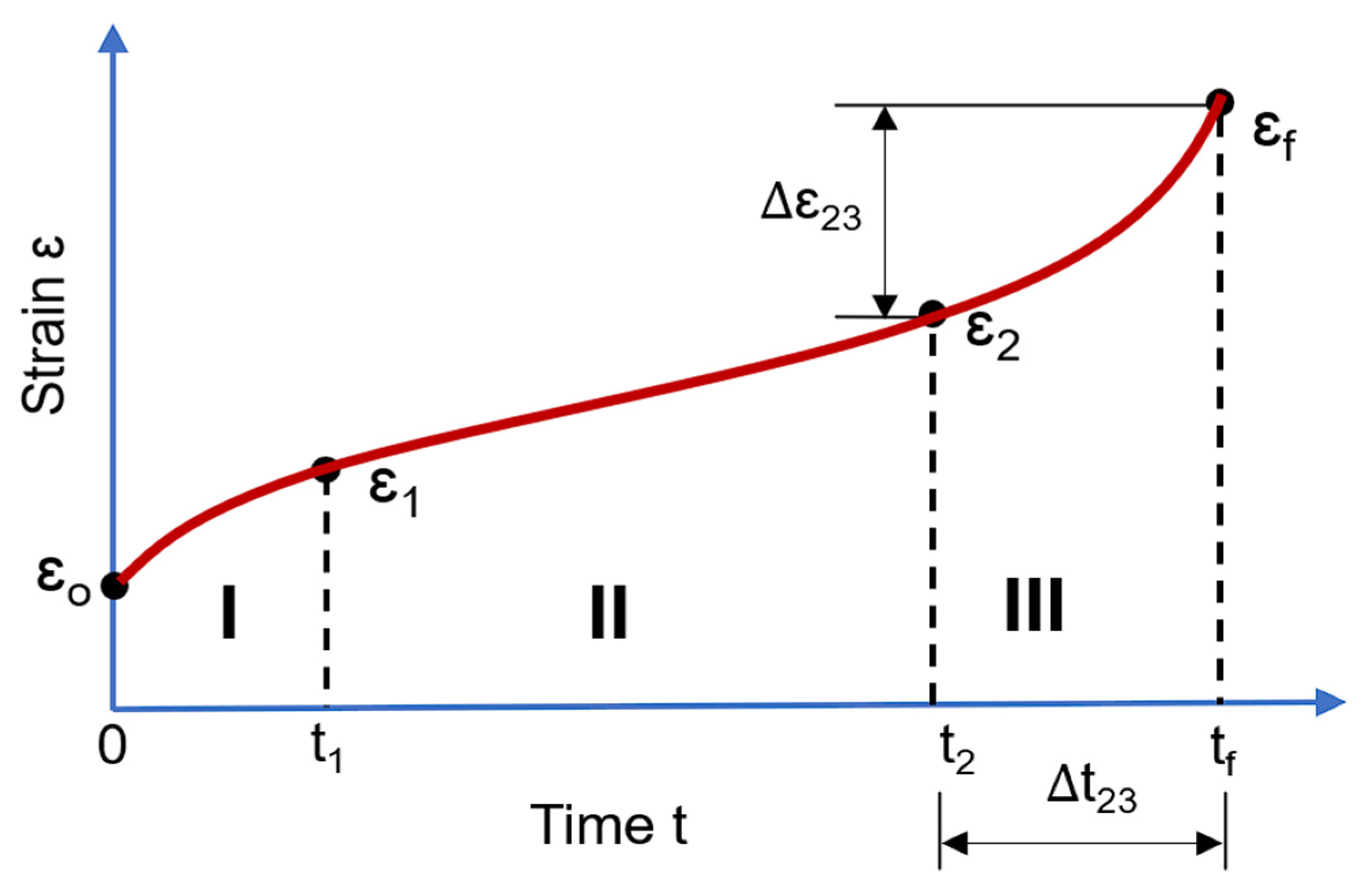
3.1. Creep Curve Characteristics
3.2. Mathematical Model
- —steady-state creep rate;
- tf—failure time;
- n—parameter characterizing damage rate;
- q—parameter characterizing accelerated creep rate;
- t—time: 0 ≤ t ≤ tf; 0 ≤ t/tf ≤ 1.
3.3. Levenberg–Marquardt Method
- I—identity matrix;
- λ—the Marquardt parameter;
- p—search direction;
- —step number.
4. Results and Discussion
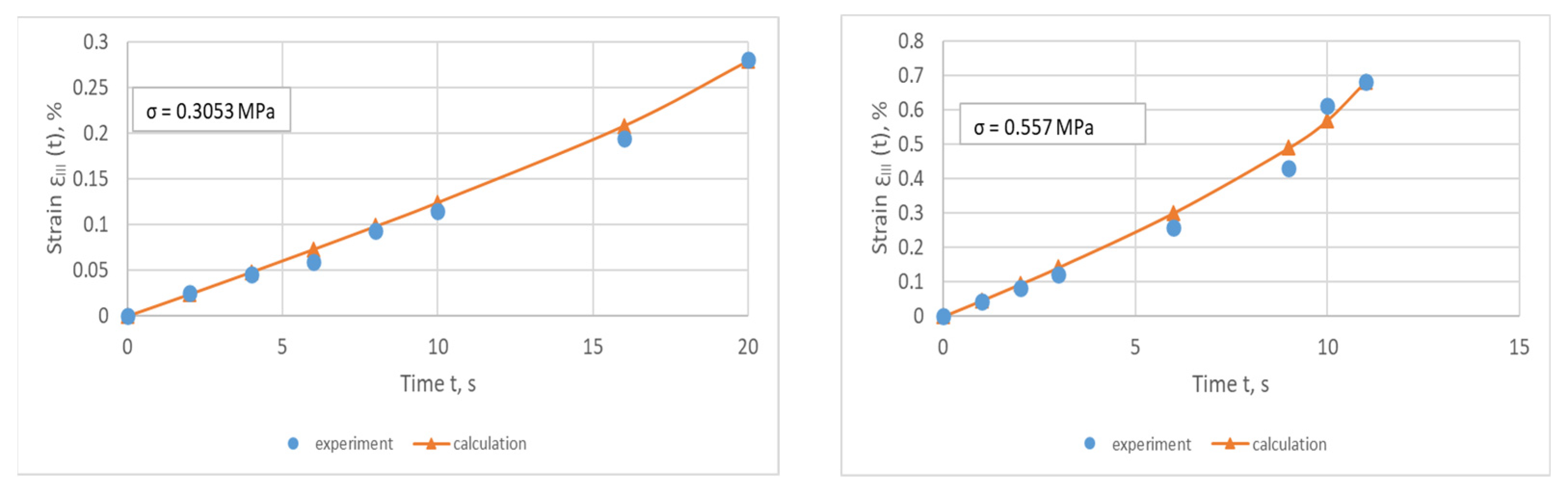
4.1. Approximation of Accelerated Creep
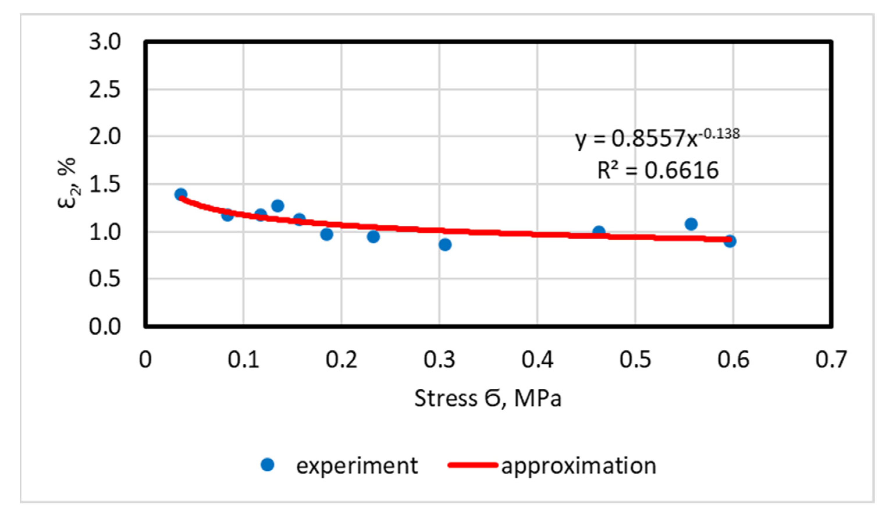
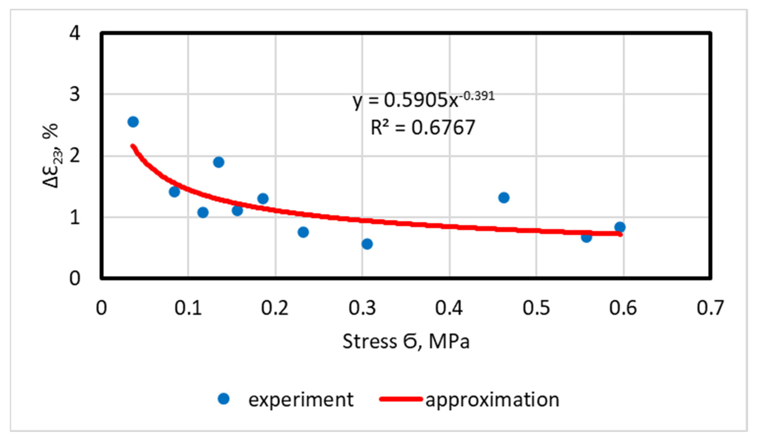
4.2. Deformation Characteristics
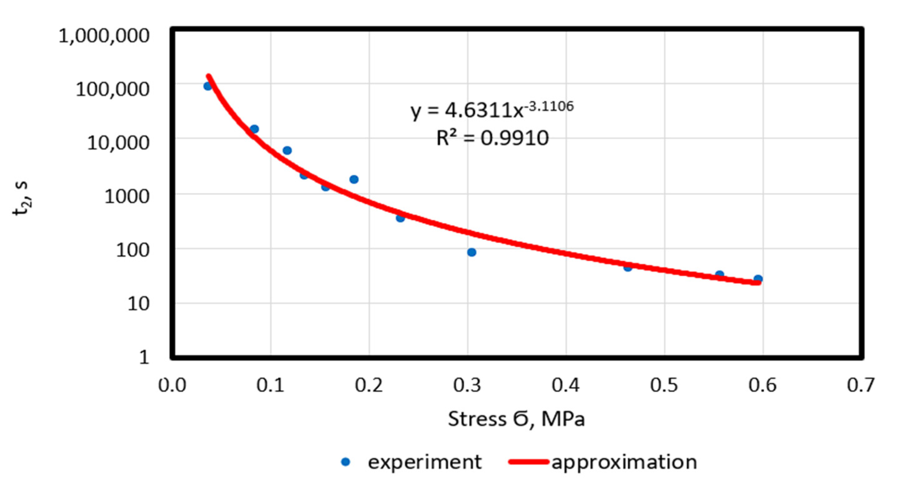
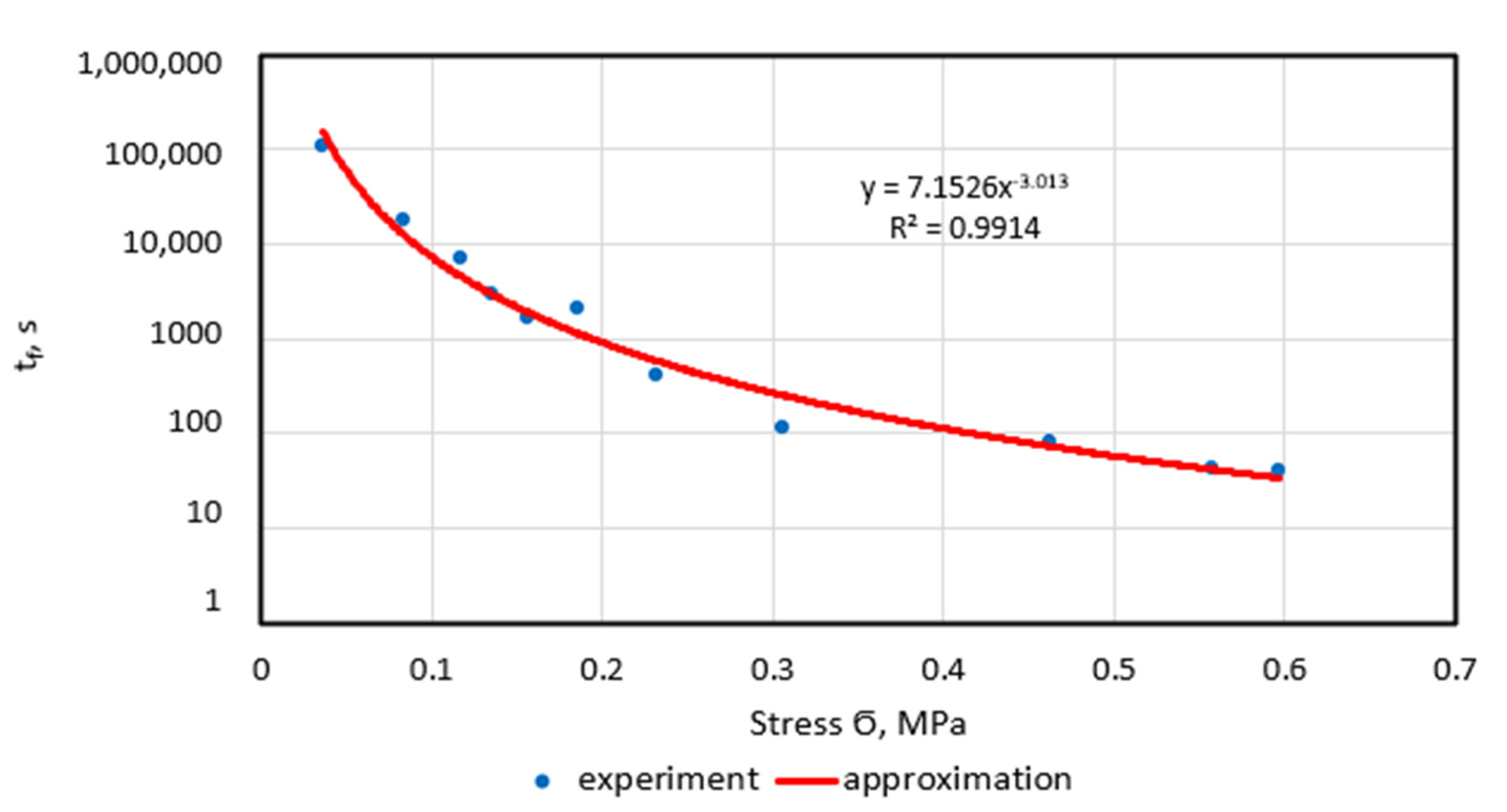
4.3. Time Characteristics
5. Conclusions
- A mathematical model is proposed that has physical meaning and satisfactorily approximates the accelerated creep of asphalt concrete. The model includes strain and time of failure, rate of steady-state creep and parameters characterizing rates of damage and deformation at the stage of accelerated creep. In order to determine with high accuracy the parameters n and q of the model when approximating the accelerated creep strains, the Levenberg–Marquardt method is used and is implemented in MatCAD 14. A brief description of the Levenberg–Marquardt method is given.
- The initial accelerated creep strain, failure strain and accelerated creep strain decrease with increasing stress. Their stress dependencies are described by power functions. It has been established that only small stresses (up to 0.2 MPa) affect the deformation characteristics of the accelerated creep of asphalt concrete, while medium and large stresses (from 0.2 MPa to 0.6 MPa) have practically no effect. The relative accelerated creep strain (the ratio of the accelerated creep strain to the failure strain) at different stresses is 38.6–64.8%, with an average value of 51%. In other words, the total strain accumulated at the accelerated creep stage is, on average, equal to half the failure strain.
- There are reliable correlation dependences at the start and end points of the accelerated creep section, as well as throughout the duration of the accelerated creep section on the stress, described with high accuracy by power functions. A strong influence of stress occurs at its low values (up to 0.3 MPa). The relative duration of accelerated creep (the ratio of the duration of accelerated creep to the long-term strength) does not depend on stress and is equal to 0.35, i.e., the duration of accelerated creep is equal to one third of the failure time.
- The phenomenon of maintaining the deformation characteristics of the accelerated creep of asphalt concrete at medium and high stresses (from 0.2 MPa to 0.6 MPa) can be explained by the fact that, with an increase in stress, the effect of increasing the deformation rate and the effect of reducing the duration of the accelerated creep period are completely mutually compensated; in other words, with an increase in stress, due to a reduction in the time of action of the load, the strain does not have time to develop. This finding is of great practical importance, as, since the processes of damage accumulation and destruction of asphalt concrete pavements are significantly influenced by the values of the load from the axles (wheels) of vehicles, in models of road pavements, including tensile strain in asphalt concrete layers, the values of the deformation characteristics of asphalt concretes can be taken as being the same for medium and heavy vehicles.
- The limitations of the current research are that the accelerated creep of asphalt concrete was investigated only at temperatures of 22–24 °C and that the effect of stress on the n and q parameters of the model was not assessed. It is recommended that similar experimental studies at other temperatures are carried out in the future to establish the temperature dependences of the characteristics of the accelerated creep of asphalt concrete and, based on the results of these studies, determine the effect of stress on the n and q parameters of the model.
Author Contributions
Funding
Institutional Review Board Statement
Informed Consent Statement
Data Availability Statement
Conflicts of Interest
References
- Yoder, E.J.; Witczak, M.W. Principles of Pavement Design; John Wiley & Sons Inc.: Hoboken, NJ, USA, 1975. [Google Scholar]
- Huang, Y.H. Pavement Analysis and Design, 2nd ed.; Pearson Education Inc.: Upper Saddle River, NJ, USA, 2004. [Google Scholar]
- Papagiannakis, A.T.; Masad, E.A. Pavement Design and Materials; John Wiley & Sons Inc.: Hoboken, NJ, USA, 2008. [Google Scholar]
- ST RK ST RK 1218-2003; Organic Binding Materials for Road and Airfield Construction. Test Methods. Kazakhstan Institute of Standardization and Metrology: Astana, Kazakhstan, 2003.
- National Research Council. Chapter 3. Design of new and reconstructed flexible pavements. In Guide for Mechanistic-Empirical Design of New and Rehatated Pavement Structures. Final Report. Part 3. Design Analysis. National Cooperative Highway Research Program (NCHRP); Transportation Research Board; National Research Council: Washington, DC, USA, 2004. [Google Scholar]
- SP RK 3.03-104-2014*; Design of Flexible Pavements. Kazakhstan Institute of Standardization and Metrology: Astana, Kazakhstan, 2019.
- Teltayev, B.; Iskakbayev, A.; Rossi, C.O.; Abu, B.D. Unsteady-state creep of an asphalt concrete. Appl. Sci. 2022, 12, 1615. [Google Scholar] [CrossRef]
- Iskakbayev, A.I.; Teltayev, B.B.; Rossi, C.O. Steady-state creep of asphalt concrete. Appl. Sci. 2017, 7, 142. [Google Scholar] [CrossRef]
- Teltayev, B.B.; Iskakbayev, A.I.; Abu, B.D. Steady-state deformation of asphalt concrete. Contr. Build. Mater. 2022, 349, 128754. [Google Scholar] [CrossRef]
- Novozhilov, V.V. On the prospects of the phenomenological approach to the problem of fracture. In Mechanics of Deformable Bodies and Structures; Mechanical Engineering: Moscow, Russia, 1975; pp. 349–359. [Google Scholar]
- AASHTO TP 124-2018; Standard Method of Test for Determining the Fracture Potential of Asphalt Mixtures Using the Flexibility Index Test (FIT). American Association of State Highway and Transportation Officials: Washington, DC, USA, 2018.
- Wagoner, M.P.; Buttlar, W.G.; Paulino, G.H. Development of a single-edge notched beam test for asphalt concrete mixtures. J. Test. Eval. 2005, 33, 452–460. [Google Scholar] [CrossRef]
- Kim, H.; Wagoner, P.M.; Buttlar, W.G. Micromechanical fracture modeling of asphalt concrete using a single-edge notched beam test. Mater. Struct. 2008, 42, 677–689. [Google Scholar] [CrossRef]
- Wagoner, M.; Buttlar, W.; Paulino, G.; Blankenship, P. Investigation of the fracture resistance of hot-mix asphalt concrete using a disk-shaped compact tension test. Transp. Res. Rec. 2005, 1929, 183–192. [Google Scholar] [CrossRef]
- Saha, G.; Biligiri, K.P. Fracture properties of asphalt mixtures using semi-circular bending test: A state-of-the-art review and future research. Constr. Build. Mater. 2016, 105, 103–112. [Google Scholar] [CrossRef]
- EN 12697-46; Bituminous Mixtures. Test Method for Hot Mix Asphalt. Part 46: Low Temperature Cracking and Properties by Uniaxial Tension Tests. European Committee for Standardization: Bruxelles, Belgium, 2020.
- Iskakbayev, A.I.; Teltayev, B.B.; Yestayev, K.Z.; Abu, B.D. Long-term strength of asphalt concrete and its applications. Constr. Build. Mater. 2020, 244, 118325. [Google Scholar] [CrossRef]
- Rabotnov, Y.N. Creep Problems in Structural Members; North-Holland: Amsterdam, The Netherlands, 1969. [Google Scholar]
- Rabotnov, Y.N. Continuum Mechanics; Nauka: Moscow, Russia, 1988. [Google Scholar]
- Kachanov, L. Introduction to Continuum Damage Mechanics; Martinus Nijhoff Publishers: Dordrecht, The Netherlands, 1986. [Google Scholar]
- Christensen, R.M. Theory of Viscoelasticity: An Introduction; Academic Press: New York, NY, USA, 1971. [Google Scholar]
- Tschoegl, N.N. The Phenomenological Theory of Linear Viscoelastic Behavior: An Introduction; Springer: Berlin/Heidelberg, Germany, 1989. [Google Scholar]
- Ferry, J.D. Viscoelastic Properties of Polymers, 3rd ed.; Willey: New York, NY, USA, 1980. [Google Scholar]
- Volkov, M.I.; Zolotarev, V.A. On the temperature-time dependence of asphalt concrete strength. News High. Edu. Inst. Constr. Arc. 1970, 3, 144–147. [Google Scholar]
- Zolotarev, V.A.; Titar, V.S. On the long-term strength of asphalt concrete over a wide temperature range. News High. Edu. Inst. Constr. Arc. 1981, 11, 83–87. [Google Scholar]
- Kiryukhin, G.N. On the issue of long-term strength of asphalt concrete. In Proceedings of SoyuzdorNII. Issue 99. Increasing the Stability of Road Surfaces Constructed Using Organic Binders; SoyuzdorNII: Moscow, Russia, 1977. [Google Scholar]
- Radovskiy, B.S.; Rudenskiy, A.V. On the influence of the characteristics of the structure of materials on their fatigue and long-term strength. In Proceedings of SoyuzdorNII. Issue 79. Improving the Quality of Asphalt Concrete; SoyuzdorNII: Moscow, Russia, 1975. [Google Scholar]
- Kiryukhin, G.N. Residual deformations in asphalt concrete pavements. Int. J. Sci. Eng. Roads. 1998, 3, 14–16. [Google Scholar]
- Luo, W.; Li, B.; Zhang, Y.; Yin, B.; Dai, J. A Creep Model of Asphalt Mixture Based on Variable Order Fractional Derivative. Appl. Sci. 2020, 10, 3862. [Google Scholar] [CrossRef]
- Golalipour, A. Asphalt material creep behavior. In Creep Characteristics of Engineering Materials; IntechOpen: London, UK, 2020. [Google Scholar]
- Büchner, J.; Wistuba, M.P.; Hilmer, T. Creep Properties of Asphalt Binder, Asphalt Mastic and Asphalt Mixture. In Proceedings of the RILEM International Symposium on Bituminous Materials, ISBM 2020, Lyon, France, 14–16 December 2020; RILEM Bookseries. Springer: Cham, Switzerland, 2022; Volume 27. [Google Scholar]
- ST RK 1225-2019; Road, Airfield Asphalt Concrete Mixtures and Asphalt Concrete. Technical Specifications. Kazakhstan Institute of Standardization and Metrology: Astana, Kazakhstan, 2019.
- ST RK 1373-2013; Bitumens and Bitumen Binders. Oil Road Viscous Bitumens. Technical Specifications. Kazakhstan Institute of Standardization and Metrology: Astana, Kazakhstan, 2013.
- BS EN 12697-33; Bituminous Mixtures. Test Method for Hot Mix Asphalt. Part 26: Specimen Prepared by Roller Compactor. British Standards: London, UK, 2003.
- Teltayev, B. A new failure criterion for asphalt mixtures under fatigue loading. Int. J. Pavem. Res. Technol. 2015, 8, 276–282. [Google Scholar]
- Ansari, K.A. An Introduction to Numerical Methods Using Math CAD 14; Schroff Development Corporation: Mission, KS, USA, 2008. [Google Scholar]
- Gill, P.E.; Wright, M.H. Practical Optimization; Academic Press Limited: London, UK, 1981. [Google Scholar]


| Characteristic Designation | Characteristic Name | Brief Description |
|---|---|---|
| I | section of unsteady-state creep | the first section of creep curve within which strain rate decreases |
| II | section of steady-state creep | the second section of creep curve within which strain rate is constant |
| III | section of accelerated creep | the third section of creep curve within which strain rate increases; at the end of this section the test specimen fails |
| εo | conditionally instantaneous strain | the value of εo depends on magnitude and duration (rate) of full load application |
| ε1 | strain at the end of section I (at the beginning of section II) of creep curve; limiting strain of hardening | maximum strain in section I (minimum strain in section II) of creep curve |
| ε2 | strain at the end of section II (at the beginning of section III) of creep curve | maximum strain in section II (minimum strain in section III) of creep curve |
| εf | failure strain | maximum strain on creep curve (also in section III) corresponding to failure time tf |
| Δε23 | total strain of accelerated creep | total strain realized in section of accelerated creep |
| t1 | unsteady-state creep duration; limiting time of hardening | at this time point unsteady-state creep ends; from this time point steady-state creep begins |
| t2 | the moment in time corresponding to the end of steady-state creep and the beginning of accelerated creep | at this time point steady-state creep ends; from this time point accelerated creep begins |
| tf | failure time | t this time point failure of the test sample occurs |
| Δt23 | accelerated creep duration | during this period of time accelerated creep is realized |
| Stress σ, MPa | Steady-State Creep Rate έII, %/C | Failure Time tf, c | Parameters | ||
|---|---|---|---|---|---|
| n | q | ||||
| 0.0840 | 0.6367 × 10⁻⁴ | 1800 | 1.0729 | 1.3500 | 0.3488 |
| 0.1566 | 8.2298 × 10⁻⁴ | 180 | 1.3147 | 0.7798 | 0.6631 |
| 0.1852 | 5.8545 × 10⁻⁴ | 180 | 0.8388 | 0.9654 | 0.4750 |
| 0.2323 | 30.9657 × 10⁻⁴ | 40 | 0.5854 | 0.7843 | 0.5053 |
| 0.3053 | 92.2767 × 10⁻⁴ | 20 | 0.1099 | 0.3895 | 0.6491 |
| 0.5570 | 305.5211 × 10⁻⁴ | 11 | 0.9998 | 1.0758 | 0.4621 |
Disclaimer/Publisher’s Note: The statements, opinions and data contained in all publications are solely those of the individual author(s) and contributor(s) and not of MDPI and/or the editor(s). MDPI and/or the editor(s) disclaim responsibility for any injury to people or property resulting from any ideas, methods, instructions or products referred to in the content. |
© 2024 by the authors. Licensee MDPI, Basel, Switzerland. This article is an open access article distributed under the terms and conditions of the Creative Commons Attribution (CC BY) license (https://creativecommons.org/licenses/by/4.0/).
Share and Cite
Iskakbayev, A.; Teltayev, B.; Aitbayev, Y.; Zhaisanbayev, A. Accelerated Creep of Asphalt Concrete at Medium Temperatures. Appl. Sci. 2024, 14, 9393. https://doi.org/10.3390/app14209393
Iskakbayev A, Teltayev B, Aitbayev Y, Zhaisanbayev A. Accelerated Creep of Asphalt Concrete at Medium Temperatures. Applied Sciences. 2024; 14(20):9393. https://doi.org/10.3390/app14209393
Chicago/Turabian StyleIskakbayev, Alibay, Bagdat Teltayev, Yerbol Aitbayev, and Azamat Zhaisanbayev. 2024. "Accelerated Creep of Asphalt Concrete at Medium Temperatures" Applied Sciences 14, no. 20: 9393. https://doi.org/10.3390/app14209393
APA StyleIskakbayev, A., Teltayev, B., Aitbayev, Y., & Zhaisanbayev, A. (2024). Accelerated Creep of Asphalt Concrete at Medium Temperatures. Applied Sciences, 14(20), 9393. https://doi.org/10.3390/app14209393