Article

Research on Excavation Method for Soft Rock Tunnel Based on Stress Release Rate

Key Laboratory of Transportation Tunnel Engineering, Ministry of Education, Southwest Jiaotong University, Chengdu 610031, China
*
Author to whom correspondence should be addressed.
Appl. Sci. 2024, 14(2), 668; https://doi.org/10.3390/app14020668
Submission received: 13 December 2023 / Revised: 5 January 2024 / Accepted: 8 January 2024 / Published: 12 January 2024
(This article belongs to the Special Issue Advances in Tunneling and Underground Engineering)

Abstract

:
A test method for controlling the stress release rate of the tunnel by adjusting the confining pressure is proposed based on the engineering background of Dongmachang No. 1 Tunnel of Huali Expressway to explore a suitable excavation method of soft rock tunnel. Based on the relationship between stress release rate, displacement release rate, and longitudinal advance of excavation face, the model test of tunnel excavation is carried out. On this basis, combined with the horizontal loading test and field monitoring results, the influence of three excavation methods, the three-bench method, three-bench with reserved core soil method, and three-bench seven-step method, on the mechanical behavior of the tunnel is studied. The research shows that the load shared by the double-layer initial support is not equal, and the second-layer initial support only bears 20% of the pressure of the first-layer initial support; replacing the three-bench method with the three-bench core soil method and the three-bench seven-step method can reduce the deformation of the surrounding rock by 8.7~12.4%, and the load borne by the supporting structure is transferred from the second layer to the first layer. In order to take into account the safety and efficiency of tunnel construction, it is recommended to use the three-bench core soil method for excavation. The research results can provide a theoretical reference for the construction of related tunnel projects.

1. Introduction

With the continuous development of China’s infrastructure, the transportation network planning has gradually shifted to the southwest region, and a large number of tunnels need to be built in the complex and dangerous central and western mountainous areas [1]. The soft rock strata in this area are widely distributed, the rock mass is loose and broken, the tectonic movement is active, the stress conditions are complex, and the large deformation of soft rock is serious [2,3,4,5]. As a result, the tunnel faces many risks and challenges in the construction process, such as geological disasters such as rock mass extrusion, collapse, and sliding [6,7], which increases the risk of tunnel construction and the possibility of safety accidents.
The tunnel excavation process is accompanied by the disturbance of the surrounding rock mass, which leads to the release of stress and the accumulation of displacement [8]. Stress release is an important research issue in tunnel excavation design, and relevant scholars have carried out a certain number of studies on it. Xu et al. [9] compared the Deformation Reserved (DR) method and the Pilot Heading (PH) method to reduce the load of the supporting structure and the stress release effect of the surrounding rock under different conditions and pointed out that the PH method is more suitable for stress release under the condition of high ground stress soft rock. Qiu et al. [10] deduced the theoretical expressions of various viscoelastic models based on the creep effect of soft rock, considering the influence of stress release of the surrounding rock, and analyzed the relationship between the tunnel excavation rate and stress release coefficient. Combined with numerical simulation and field monitoring, Shen et al. [11] analyzed the stress release law and surrounding rock deformation characteristics when using the semi-central diaphragm method (SCDM) for tunnel excavation. Neuner et al. [12] compared and analyzed the stress release law of surrounding rock of time-dependent nonlinear 3D and 2D models using finite difference software and field monitoring data and proposed a modified time-dependent 2D model.
The stress release is closely related to the excavation method of the tunnel, and the order and method of tunnel excavation are two of the key factors that control the deformation of the surrounding rock. Choosing the appropriate excavation method can control the large deformation of soft rock to a certain extent [13], which has important engineering significance. At present, the excavation of soft rock tunnels mainly adopts the step method or other partial excavation methods [14,15]. The construction method of partial excavation can ensure the stability of the surrounding rock and supporting structure in the construction process, but at the same time, there are a series of problems, such as complicated processes, mutual interference, and insufficient construction space, and the construction efficiency is relatively low. With the innovation of tunnel design concepts and construction technology, the full-face excavation method has been widely used because of its advantages of fewer process connections, relatively large working spaces, and high construction efficiency. The cases of this method applied to soft rock tunnels are also increasing [16,17,18]. Enlarging the tunnel excavation face to the full section can provide sufficient working space for mechanical equipment and simplify the process, but the self-stability of the tunnel face is reduced, and the construction risk is increased.
It can be seen that both step-by-step excavation and full-face excavation have their own advantages and disadvantages, so many scholars carry out further research based on traditional excavation methods. Cui et al. [19,20] compared the control effect of the three-bench method and the pilot tunnel expansion method on the large deformation of soft rock combined with field tests and numerical simulations for the strongly weathered carbonaceous slate tunnel and optimized the existing tunnel construction scheme. Fang et al. [21] used numerical simulations to explore a suitable excavation method for interbedded soft rock tunnels and pointed out that the three-bench temporary invert method had a better effect in controlling tunnel deformation, while the three-bench method had higher construction efficiency. It was suggested that the two methods should be used in combination in actual engineering excavation. Jun et al. [22] used the MIDAS/GTS software to simulate and analyze the stress and deformation law of surrounding rock under three excavation methods: positive cushion retaining method, CRD method, and bilateral drift method. They pointed out that the deformation and stress caused by excavation using the positive cushion retaining method are small. Jiang et al. [23] used a model test to explore a suitable construction method for a tunnel crossing soft loess stratum and finally selected the DSDM excavation method combined with the WSS grouting reinforcement method for optimization. In essence, the choice of different excavation methods is the mutual game between engineering safety and construction efficiency. There is no good or bad saying about the excavation method, but the appropriate excavation method should be selected according to the actual needs.
Abundant achievements have been made in the study of large deformation control and excavation methods of soft rock tunnels. However, the large deformation of soft rock tunnels is greatly affected by geological conditions, construction technology, and other factors. There are often great differences in geological conditions, supporting parameters, and section design of different tunnel projects [24]. The excavation method should be determined in combination with the actual situation of the site during the design and construction of the tunnel. At present, the research on the stress release rate of tunnel excavation is not yet mature, and the existing research methods are relatively simple. Most of the research focuses on numerical simulation, and there are few research cases of indoor model tests combined with stress release. In view of this, in order to explore the suitable excavation method for soft rock tunnel, this paper takes the Dongmachang I tunnel of the Huaping-Lijiang highway as the engineering background and combines the field monitoring results to explore the relationship between the stress release rate, displacement release rate, and longitudinal advance of the excavation face. The test method of controlling the tunnel stress release rate to simulate tunnel excavation is proposed. On this basis, the horizontal loading test is carried out to study the influence of three excavation methods, the three-bench method, the three-bench core soil method, and the three-bench seven-step method, on the mechanical behavior of the tunnel. The research results provide theoretical support for the selection of excavation methods for soft rock tunnels with similar high-ground stress fields in Southwest China.

2. Model Test Method of Soft Rock Tunnel Excavation Based on Stress Release

2.1. Engineering Background

Dongmachang No. 1 Tunnel (Figure 1) is a control project of the Huaping-Lijiang Expressway. The starting point mileage of the tunnel is ZK70 + 130, and the stopping point mileage is ZK75 + 335. The total length of the tunnel is 5205 m, and the maximum buried depth is 613 m. The elevation of the tunnel area is 1870~2512 m, and the relative height difference is 643 m. The terrain is rugged, and many bedrocks are exposed, and the soft rock accounts for a large proportion. The tunnel intersects the Chenghai-Binchuan active fault zone at K72 + 164, which is a Holocene active fault. The width of the fault zone is about 95 m. The fault occurrence is 310°∠72°, and the angle with the tunnel is 41°, which belongs to the compressive reverse fault. Affected by the fracture, the lithology of the tunnel entrance section and the exit section is quite different. The entrance section is dominated by argillaceous siltstone, and the exit section is dominated by dolomite limestone.
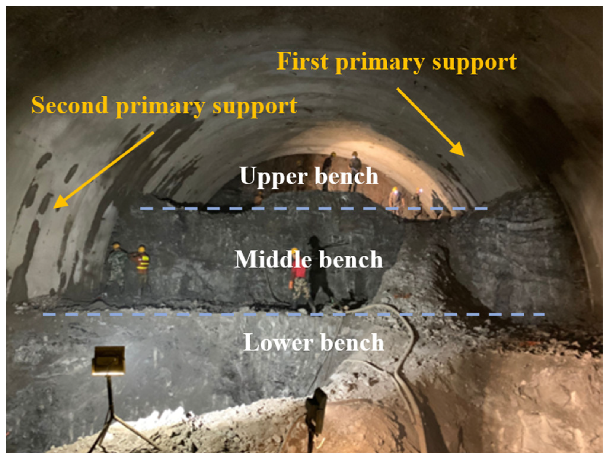
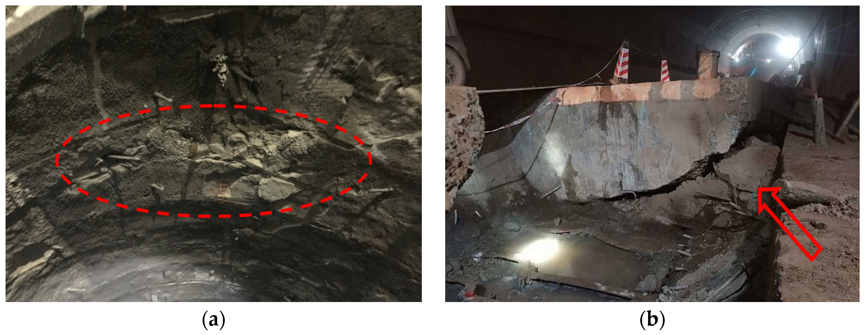
The entrance section of the tunnel is excavated using the three-bench method (Figure 2). However, due to the poor stability of the surrounding rock, the problem of large deformation of soft rock is extremely prominent. The tunnel shows the characteristics of large deformation, high deformation rate and difficult convergence, long deformation duration, and uneven deformation and failure. In the construction process, large deformation diseases of the surrounding rock, such as large deformation of initial support, invasion limit of initial support, and uplift of inverted arch, have appeared one after another (Figure 3). Combined with the actual situation of the project, the tunnel entrance section K71 + 810~K71 + 910 is selected as the typical section. The surrounding rock of this section is mainly argillaceous siltstone, which is divided into active fault influence sections after expert demonstration.
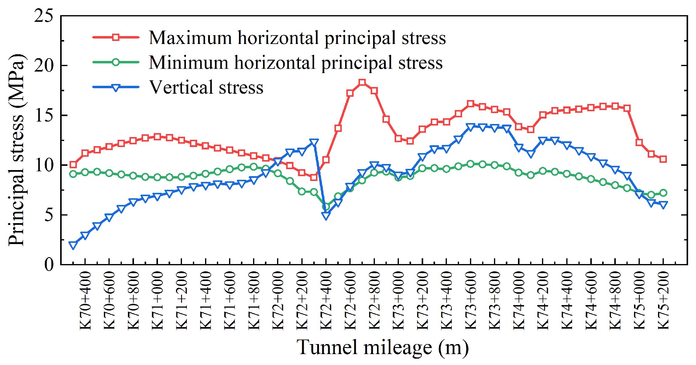
Kou et al. [25] used the hydraulic fracturing method to monitor the in situ stress and established a three-dimensional finite element model. The least squares method was used for regression inversion to obtain the in situ stress value of the rock mass in the whole area. The in situ stress inversion results along the tunnel are shown in Figure 4. Combined with the relevant in situ stress test and inversion results, it can be seen that the stress state of the stratum in the selected typical section is complex. Taking section K71 + 882 of the tunnel entrance section as an example, the in situ stress inversion results are shown in Table 1, and the tunnel passing through it is affected by the large horizontal tectonic stress.
The tunnel excavation method has a great influence on the stability of the tunnel and is one of the key factors to control the deformation of the surrounding rock. Therefore, it is of great significance to research the excavation method. Since tunnel excavation is essentially a process of stress release and displacement release, the selection of tunnel construction methods is closely related to the two. Therefore, based on the selected research section, the appropriate excavation method for the tunnel is explored from the perspective of stress release considerations. The research results can provide a reference for subsequent construction.

2.2. Displacement Releasing Rate

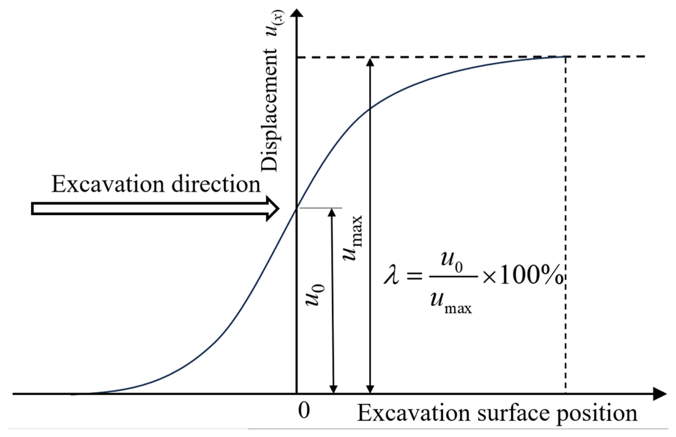
Tunnel excavation is accompanied by the deformation and displacement release of the surrounding rock, and the displacement release is too large due to the low strength of the surrounding rock during the excavation of a soft rock tunnel, which easily produces large deformation diseases. In the process of advancing the tunnel excavation face, the surrounding rock begins to settle and deform at a certain distance from any unexcavated face. The radial displacement of the surrounding rock does not converge until the excavation face passes a certain distance from the target section. The relationship between the deformation of the tunnel and the position of the excavation face is shown in Figure 5, u(x) is the radial displacement corresponding to the target section when the excavation face is in any position. The displacement release rate at any section around the tunnel can be obtained by the ratio of the radial displacement to the maximum radial displacement when the tunnel is excavated to the section. The displacement release rate is deduced as follows [26]:
λ = u 0 u max × 100 %
where λ is the displacement release rate; u0 is the radial displacement of any section of the tunnel from the beginning of deformation to the excavation; umax is the maximum radial displacement of the same section after the deformation is stable.
A ring tunnel deformation monitoring section is set up every 5 m in the research section. A total of seven measuring points are set up along the inner wall of the tunnel in each monitoring section, three measuring points are set up for the vault subsidence, and one deformation measuring point is set up on each side of the spandrel and arch waist position.
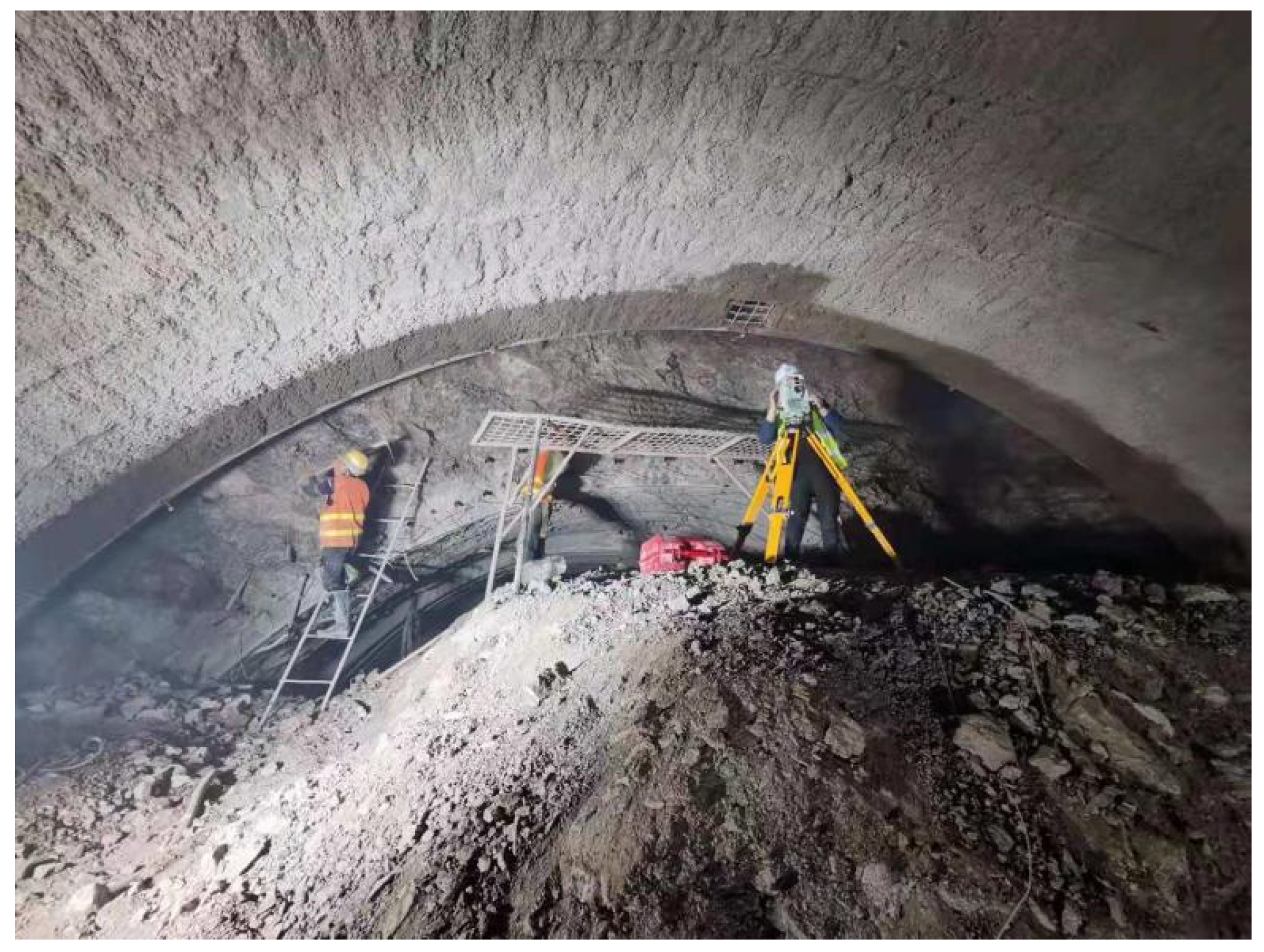
In order to study the on-site displacement release of the tunnel, the pile number K71 + 882 at the entrance section of the Dongmachang I tunnel was selected as a typical monitoring section to monitor the vertical settlement (G1, G2, G3) and horizontal convergence (BC, DE) at the top of the tunnel during the construction period. The layout of monitoring points is shown in Figure 6. The total station was used as the displacement monitoring equipment, and the non-contact three-dimensional displacement observation method was used to monitor the deformation of surrounding rock, as shown in Figure 7.
The tunnel displacement monitoring frequency was once a day, and the final displacement of the tunnel was recorded every day. The deformation time history and deformation rate curve of the K71 + 882 monitoring section tunnel are drawn, as shown in Figure 7. Because the tunnel can be regarded as being excavated at a uniform speed of one meter per day in practical engineering, the excavation face advancing distance can be characterized by time, and the displacement change curve with time is equivalent to the relationship curve between the displacement and excavation face position, and the displacement release change rule is basically consistent with Figure 5.
Figure 8 shows that the deformation of the surrounding rock lasts for a long time, and the deformation rate decreases logarithmically, showing obvious creep characteristics. After the excavation of the tunnel monitoring section, the displacement around the tunnel increases sharply, and the maximum deformation rate is about 62 mm/d. With the excavation of the tunnel, the deformation rate shows a decreasing trend. After about 25 days of construction of the monitoring section, the deformation rate of the tunnel tends to be stable at this time, which is basically stable below 10 mm/d. It shows that the application of double-layer support can effectively control the displacement around the tunnel and ensure the safety of tunnel construction. The deformation around the tunnel is dominated by vault settlement. The maximum vertical displacements of the three monitoring points (G1, G2, G3) at the arch bottom are 319.27 mm, 348.95 mm, and 340.06 mm, respectively.

2.3. Stress Release Rate

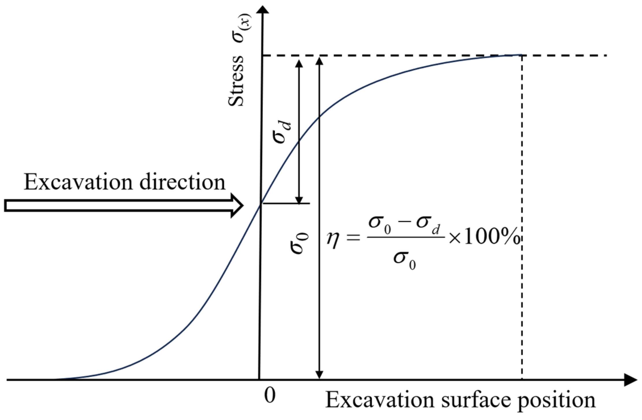
The displacement release of the tunnel is accompanied by stress release. When the excavation face is a certain distance away from an unexcavated section, the stress redistribution begins to occur in the target section. The constraint stress generated by the surrounding rock on the proposed excavation boundary of the section is defined as the initial stress. With the continuous advancement of the excavation face, the constraints on the excavation boundary of the section are continuously reduced until the tunnel face passes through the section and has a certain distance. The constraint is reduced to 0, which is the stress release process accompanied by tunnel excavation. The relationship between the stress release and the position of the excavation face is shown in Figure 9. σ(x) is the constraint stress release value corresponding to the target section when the excavation face is at any position. The definition of the stress release rate at any point around the tunnel can be obtained by the ratio of the reduction in the constraint stress to the initial stress. The stress release rate is deduced as follows [27]:
η = σ 0 σ d σ 0 × 100 %
where σd is the constraint stress generated by the surrounding rock after the tunnel target section is excavated; σ0 is the initial stress; η is the stress release rate.
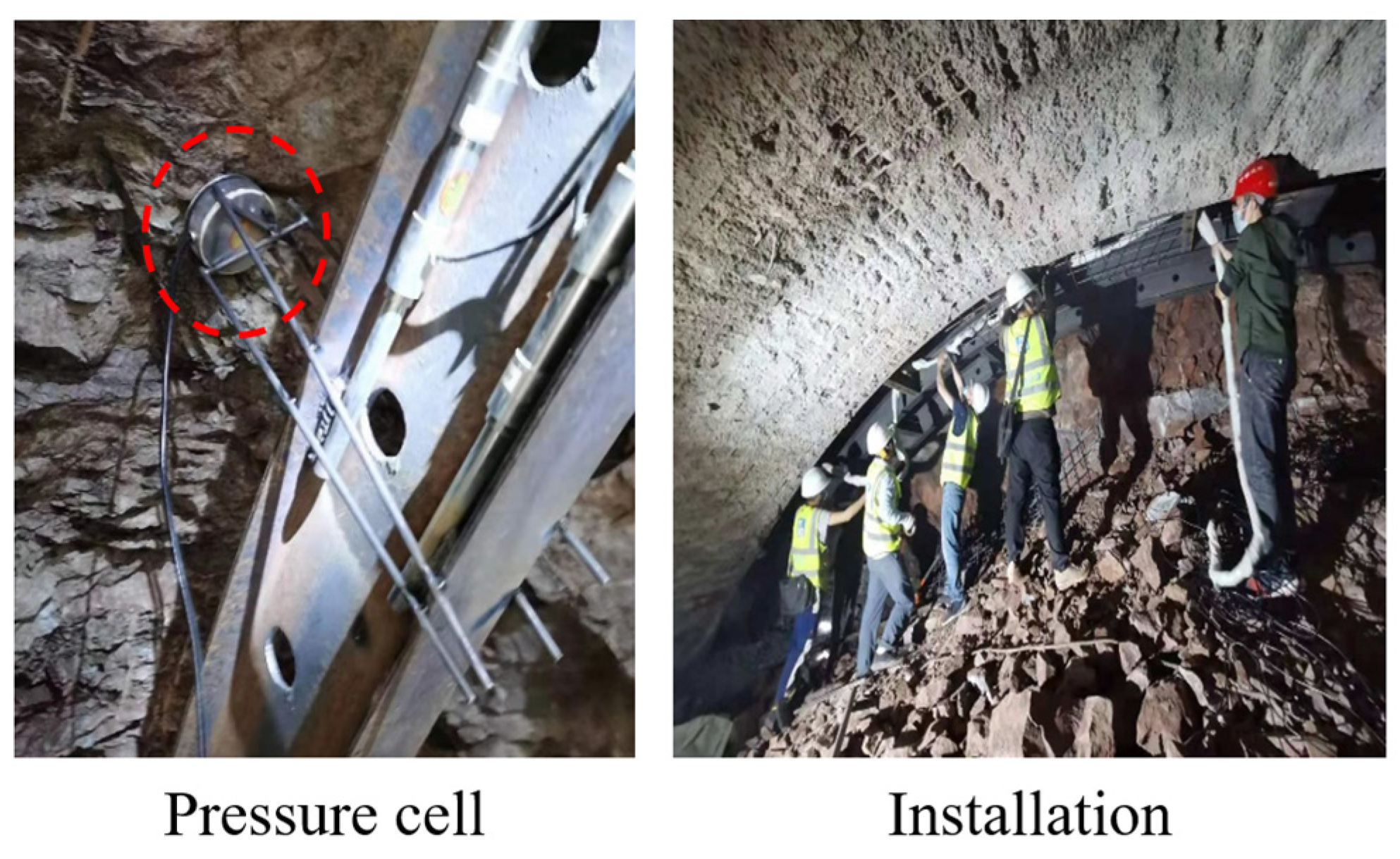
In order to study the stress release of the tunnel site, the K71 + 882 section of the entrance section of the Dongmachang I tunnel was selected as a typical monitoring section. After the tunnel was excavated and the steel arch was arranged, the pressure cell was installed between the primary support and the surrounding rock to monitor the contact pressure, as shown in Figure 10. The contact stress between the initial support and the surrounding rock at the tunnel vault (A), left and right arch shoulder (B, C), and left and right arch waist (D, E) during the construction period was monitored, respectively. The layout of the monitoring points is shown in Figure 11.
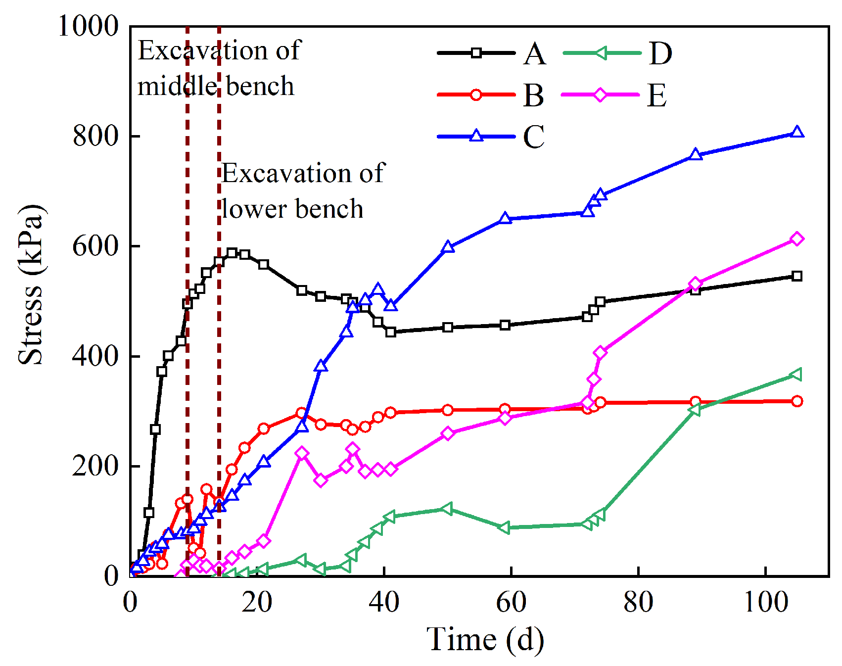
The variation curve of the tunnel stress with time is shown in Figure 12. According to the definition of stress release rate, the contact stress between the surrounding rock and the initial support is the result of the release of the constraint stress of the surrounding rock on the boundary of the section to be excavated. Because the tunneling speed is constant, the stress change curve of Figure 12 can be equivalent to the relationship between the stress release of the tunnel and the position of the excavation surface. At this time, both Figure 9 and Figure 12 can represent the relationship between the stress release coefficient and the advance distance of the excavation surface, and the shape of the two curves is similar. It can be seen from Figure 12 that the stress change in the tunnel’s surrounding rock lasts for a long time. In the early stage of monitoring, the stress of the tunnel vault increases sharply and reaches the peak value of 588.05 kpa after the excavation of the lower bench (14th day). The stress at the arch shoulder and arch waist increases steadily with time, and the growth rate decreases gradually. After 100 days, the stress change range is small, which can be regarded as stable. At this time, the stress at the right arch shoulder is the largest, which is 806.05 kpa, and the stress at the left arch shoulder is the smallest, which is 318.36 kpa.

2.4. The Internal Relationship between Stress Release Rate and Displacement Release Rate

Tunnel excavation will disturb the surrounding rock and remove the initial stress field constraints so that it can produce material and energy exchange with the outside world, and then the stress in the surrounding rock will gradually be released with the passage of the excavation surface. Tunnel excavation will also cause stratum movement, and the deformation of the surrounding rock gradually increases with the passage of the excavation surface and finally converges under the action of support. It can be seen that the macroscopic stress release during tunnel excavation is the displacement release of the surrounding rock. Tunnel excavation is essentially the accumulation of stress release and displacement release. Stress release and displacement release are the time-space effect problems caused by tunnel excavation. The two have a very close internal relationship.
Many scholars have carried out some research and application on the relationship between the stress release rate and displacement release rate: Zhang [28] and Heidarzadeh [29] used model tests and numerical simulations, respectively, to draw the time history curves of stress release and displacement release, and pointed out that the change trend of the two curves was similar. Cantieni et al. [30] replaced the stress release rate with a more easily controlled displacement release rate and carried out numerical simulations to analyze the deformation and stress characteristics of the supporting structure of tunnel excavation under elastoplastic conditions. Based on the assumption that the stress release rate is approximately equivalent to the displacement release rate when the tunnel excavation face is advancing, Manh et al. [31] proposed a semi-analytical solution for the deformation and stress of surrounding rock with time-varying mechanical properties.
Based on the actual project of the Dongmachang I tunnel, this paper analyzes the stress release rate and displacement release rate, respectively. The change trend of the relationship curve between tunnel deformation and excavation surface shown in Figure 5 and the relationship curve between the stress release and excavation surface shown in Figure 8 is basically the same. The law of displacement release (Figure 8) and stress release (Figure 12), measured in actual monitoring, further verifies the rationality of the assumption that the stress release rate is approximately equivalent to the displacement release rate. Because it is impossible to monitor the target section without excavating the surrounding rock in the actual project, the stress and displacement of the section can only be measured after the tunnel excavation surface passes through the target section.
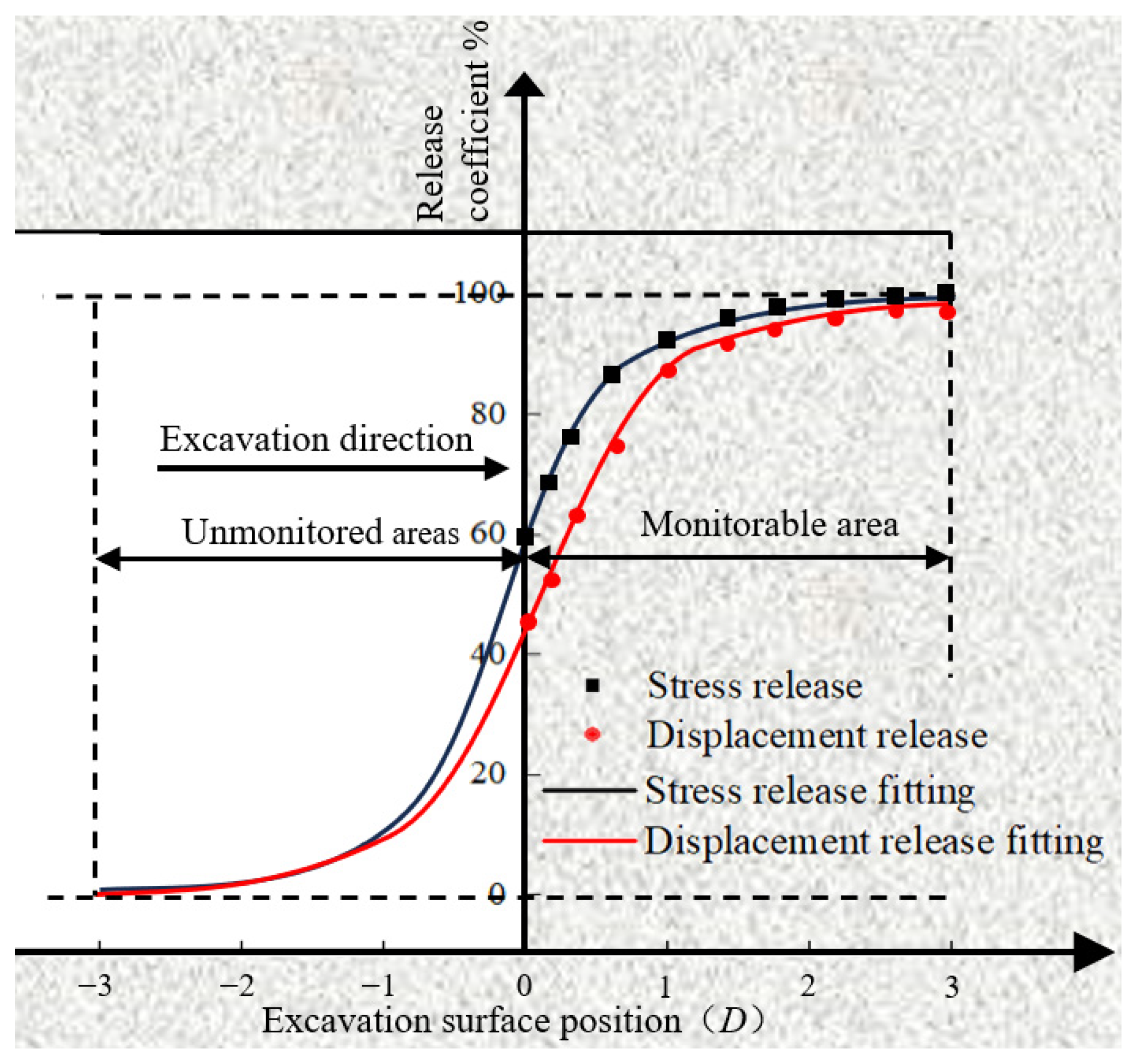
In order to further explore the relationship between stress release and displacement release, this paper converts the calculation of the measured results into the expression of the displacement release coefficient and stress release coefficient. When the distance between the excavation surface and the target surface is more than three times the diameter of the hole, the release has not yet started or has been stable, corresponding to the release coefficient of 0 and 100% in Figure 13, respectively. The measured release coefficient was fitted with the function proposed by Zhang et al. [32]:
C n = C 0 2 tanh a n b + 1
where C is the release coefficient; C 0 is the final release coefficient; n = L / D , L is the distance between the excavation surface and the target surface, and D is the tunnel diameter; a , b are parameters. When n tends to be negative infinity, the release has not yet begun, and the corresponding release coefficient C = 0 ; similarly, it can be obtained that when n tends to be positive infinity, it is fully released at this time, corresponding to the release coefficient C = C 0 = 1 . When n = b / a , the release coefficient C = C 0 / 2 = 0.5 .
Combined with the field-measured data fitting results, as shown in Figure 13, the relationship curve between the release coefficient and the position of the excavation surface is obtained. It can be seen that the stress release coefficient curve is close to the displacement release coefficient curve, which can be approximated as the displacement release rate will increase linearly with the increase in the stress release rate.

2.5. Model Test Excavation Method for Soft Rock Tunnel Based on Stress Release

The above studies have beneficially verified the strong correlation between stress release rate and displacement release rate. In order to further explore the displacement deformation and mechanical characteristics of surrounding rock under different excavation methods of soft rock tunnels with high ground stress, this paper uses a model test to carry out further research. The traditional model test often uses the model box to realize the in-situ stress loading through the loading system and excavates the model soil according to demand to simulate the actual tunnel excavation [28,33,34]. This test method can better restore the construction process of the tunnel, but there are still some shortcomings. For example, due to the limitation of site and cost, the traditional model box test usually uses a small-size model to simplify the simulation of the actual tunnel project (Figure 14), which will lead to the inability to accurately restore the three-dimensional effects in the actual project, such as the non-uniformity of the stratum, the complex boundary constraints, and the neglect of the deformation and stress transfer of the vertical direction model soil, which ultimately leads to the inability to reflect the real complex actual project.
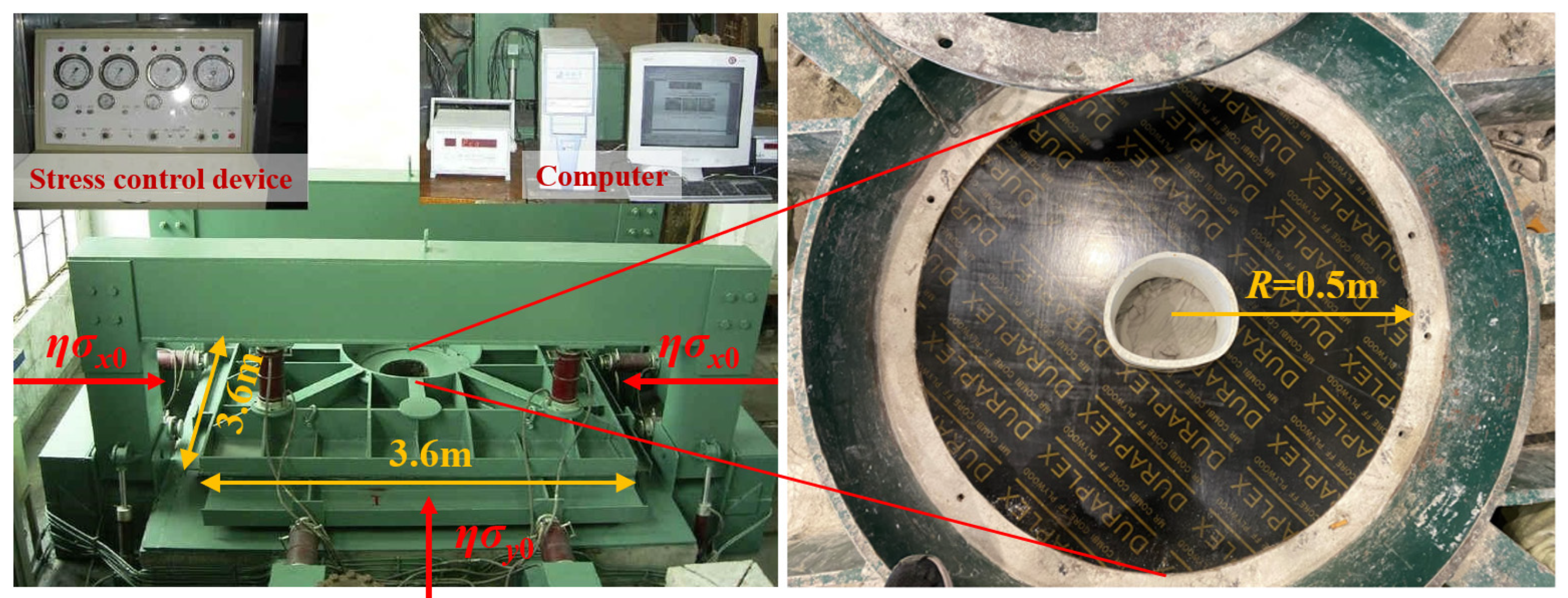
At present, the mainstream tunnel excavation simulation methods are divided into the stress release method and displacement release method, but it is difficult to achieve displacement release by directly controlling the displacement around the tunnel during simulation excavation. In view of this, based on the stress release, this paper carries out the indoor model test in the form of horizontal loading (Figure 15). Compared with the traditional model test device, the tunnel diameter in the horizontal loading model test is smaller than the size of the whole model soil. The three-dimensional effect of the underground structure can be considered, including stratum deformation, stress transfer, etc., and it has obvious advantages in terms of authenticity and data acquisition. The tunnel model and similar soil material of the test device are placed inside the device. During the test loading process, four jacks arranged in the x direction are used to simulate the horizontal pressure. Four jacks arranged in the y direction are used to simulate vertical stress. The vertical jack and the loading panel are used to constrain the cover plate to control the longitudinal displacement of the test body so that the test body is in a plane strain state during the loading process.
The test simulates the different stress release rates of the tunnel model soil by step loading. When the test is in the initial state, and no load is applied, the tunnel model is in the state before excavation, and the stress release rate is 0. When the confining pressure is gradually loaded until it is the same as the initial stress field, the state of the tunnel model is consistent with the actual tunnel after excavation. According to the definition of stress release rate Equation (2), the stress release amount at the tunnel wall should be equal to the initial stress σ0, and the stress is completely released. Therefore, the process of loading confining pressure from 0 to the initial stress field step by step corresponds to different stress release rates gradually increasing from 0. Because the stress release rate is approximately equivalent to the displacement release rate, the displacement release rate can be increased synchronously when the stress release rate is increased, which is consistent with the effect of the excavation face gradually advancing so as to realize the simulation of tunnel excavation.

3. Model Test Arrangement and Result Analysis

3.1. Preparation of Similar Materials

This model test relies on the Dongmachang I Tunnel, combined with the field geological survey data and the results of the indoor rock mechanics test. The K71 + 822 in the direction of the tunnel entrance is selected as the model test section, and the test prototype soil is argillaceous siltstone. The test is based on the geometric similarity ratio CL = 50 and the severe similarity ratio Cγ = 1, and the physical and mechanical parameters are similar according to the similarity theorem in Table 2.
According to the determined similarity ratio, the physical and mechanical parameters of the prototype soil and the model soil can be obtained, as shown in Table 3. The model soil is mainly made of barite powder, and a certain proportion of quartz sand, gesso, talc powder, and water are added at the same time. The material ratio is adjusted by combining the physical and mechanical parameters obtained from the direct shear test and triaxial compression test of the model soil. The ratio of similar materials used in the surrounding rock is shown in Table 4.
The stress states of the advanced pipes are mainly bending, and the prototype advanced pipes material and the model advanced pipes material need to meet the bending stiffness similarity ratio.
E I p E I m = C E C l 4 = 50 5
where the lower corner p represents the prototype, the subscript m represents the model, E is the elastic modulus, I is the moment of inertia of the cross-section.
In the actual project, the hot-rolled seamless steel pipe is used as the advanced pipe. After comparing and analyzing the physical and mechanical properties of different materials, the stainless steel hollow pipe with a diameter of 4.5 mm is finally used to simulate the steel pipe with a diameter of 76 mm in the actual project. The material parameters of the lead pipe shed are shown in Table 5, and the actual similarity ratio is close to the theoretical similarity ratio.
The stress state of the anchor bar is similar to that of the advanced pipes, and the load is mainly bending. In this experiment, a high-density polyethylene rod (HDPE) was selected to simulate the bolt. Firstly, the moment of inertia of the HDPE rod was calculated according to the similarity relationship of Equation (4), and then the HDPE rod with the appropriate diameter was selected according to the moment of inertia. In practical engineering, the anchor rod has a variety of different sizes, mainly including a 4 m short anchor rod, 6 m short anchor rod, and 9 m long anchor rod. According to the similarity ratio, the HDPE rod is cut into lengths of 0.08, 0.12, and 0.18 m. The material parameters of the anchor bolt are shown in Table 6, and the actual similarity ratio is close to the theoretical similarity ratio.
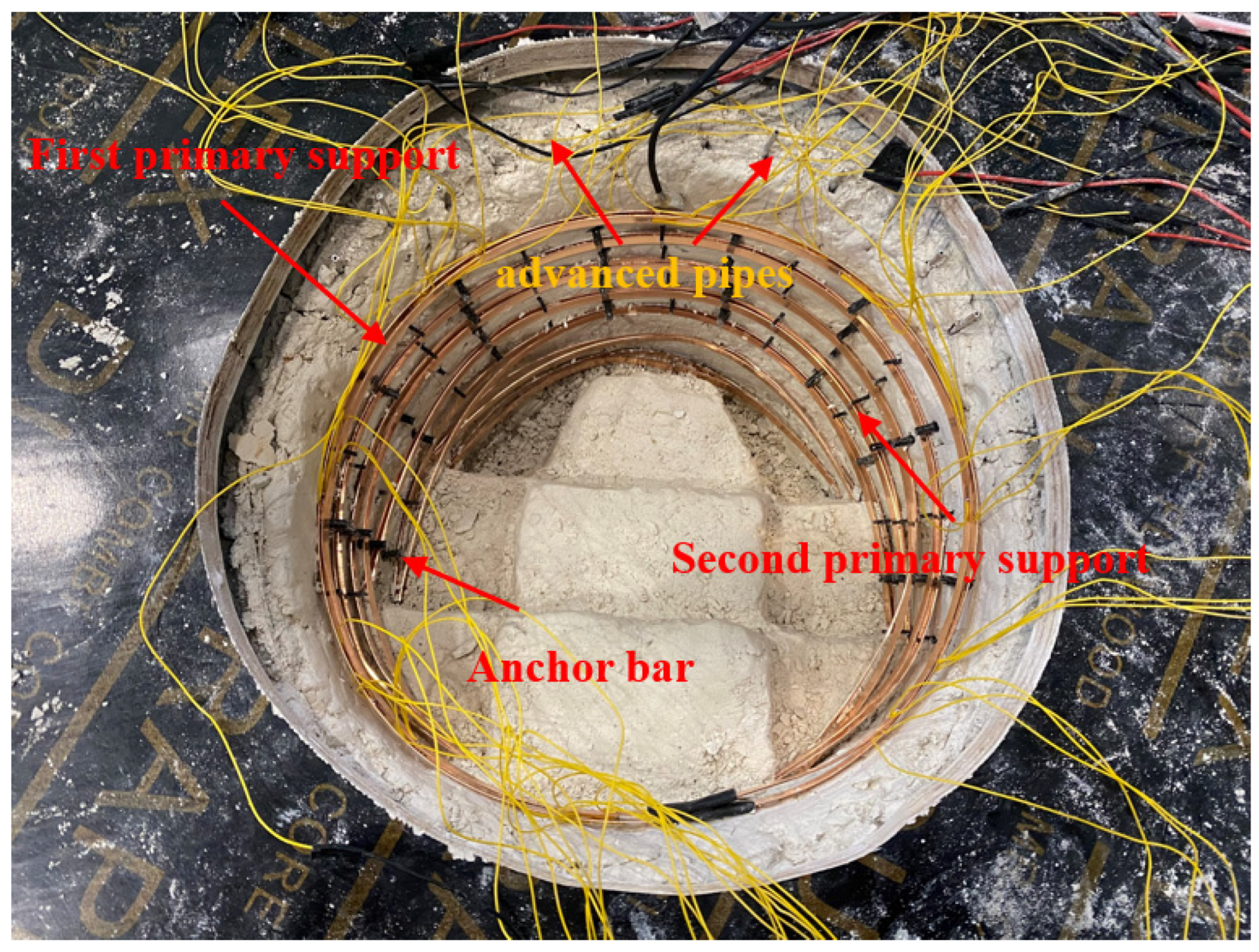
In practical engineering, the steel arch is mainly subjected to bending deformation. The material of the prototype steel arch and model steel arch should meet the similarity relationship in Equation (4). The copper strip is selected as the simulation material of the steel arch frame in the test. After the moment of inertia of the copper strip is determined by the equivalent stiffness, the section size of the copper strip can be determined. The steel arch models used in the actual construction process of the first and second floors simulated in this model test are I25b and I22b, respectively. The relevant dimensions and parameters finally determined in combination with the existing conditions are shown in Table 7. Each support in the model test is shown in Figure 16.
According to the design data of the Dongmachang No. 1 tunnel, the design grade of shotcrete used in the initial support is C25. The mixing of gypsum and water can simulate the performance of shotcrete, so similar materials are simulated by the artificial field spraying method of gypsum material with a ratio of water:gypsum = 1:1.06. The physical parameters of shotcrete are shown in Table 8.

3.2. Testing Procedures

(1)
Filling soil
According to the previously determined model soil ratio, the model soil materials are weighed, and the soft soil materials are mixed and arranged on the horizontal platform. During the filling process, the surrounding filling range is limited by the box girder. After the filling is completed, the manganese steel cover plate is placed to tamp the model soil. The test filling process is shown in Figure 17.
(2)
Excavation and support
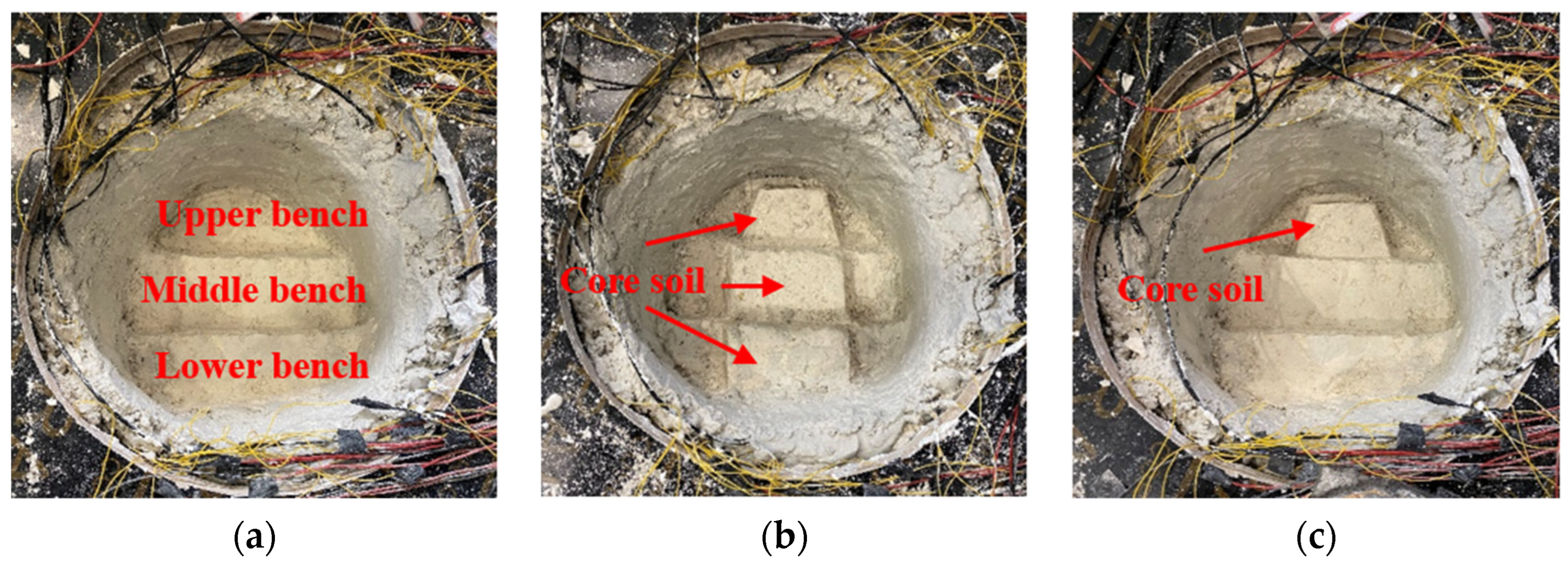
The excavation and support steps of the tunnel are as follows: (1) step-by-step artificial excavation of the tunnel; (2) installation of earth pressure box; (3) construction of steel arch; (4) application of bolt; (5) application of shotcrete; (6) placement displacement meter. Among them, the excavation depth is 20 cm, the length of each step is 6 cm, and the length of the core soil is 4 cm. The tunnel model excavation of each working condition is shown in Figure 18.
(3)
Loading
The initial stress field of section K71 + 882 is shown in Table 1. Combined with the results of the relevant in situ stress inversion calculation [25], it is learned that the direction of the maximum horizontal principal stress at the research section is perpendicular to the direction of the tunnel axis, and the direction of the minimum horizontal principal stress is parallel to the direction of the tunnel axis.
Therefore, the initial stress in the x direction is equal to the maximum horizontal principal stress, and the stress value is 10.71 MPa. The initial stress in the y direction is the vertical stress, and the stress value is 8.78 MPa. The model test loading mainly considers the horizontal tectonic stress field and the self-weight stress field of the overlying soil. In this test, the model loading process is realized using hydraulic jack pressurization in all directions. Combined with the stress similarity ratio Cσ and the test device parameters, the load in the x direction σ x is 5.82 MPa, and the load in the y direction σ y is 4.77 MPa. In order to simplify the calculation and test operation, the maximum applied load in the x direction σ x max is set to be 6.00 MPa, and the maximum applied load in the y direction σ y max is set to be 4.80 MPa. The loading starts from the initial stress of 0, and each additional load increases by 0.20 (0.16) MPa in the x(y) direction. The lateral pressure coefficient is always maintained λ = σ x σ y = 1.25 for bidirectional loading until the maximum applied load is reached to simulate the change process of the stress release rate gradually increasing from 0. A 3.00 MPa load was applied in the vertical direction (z-direction) to keep the test in a plane strain state.
(4)
Monitoring
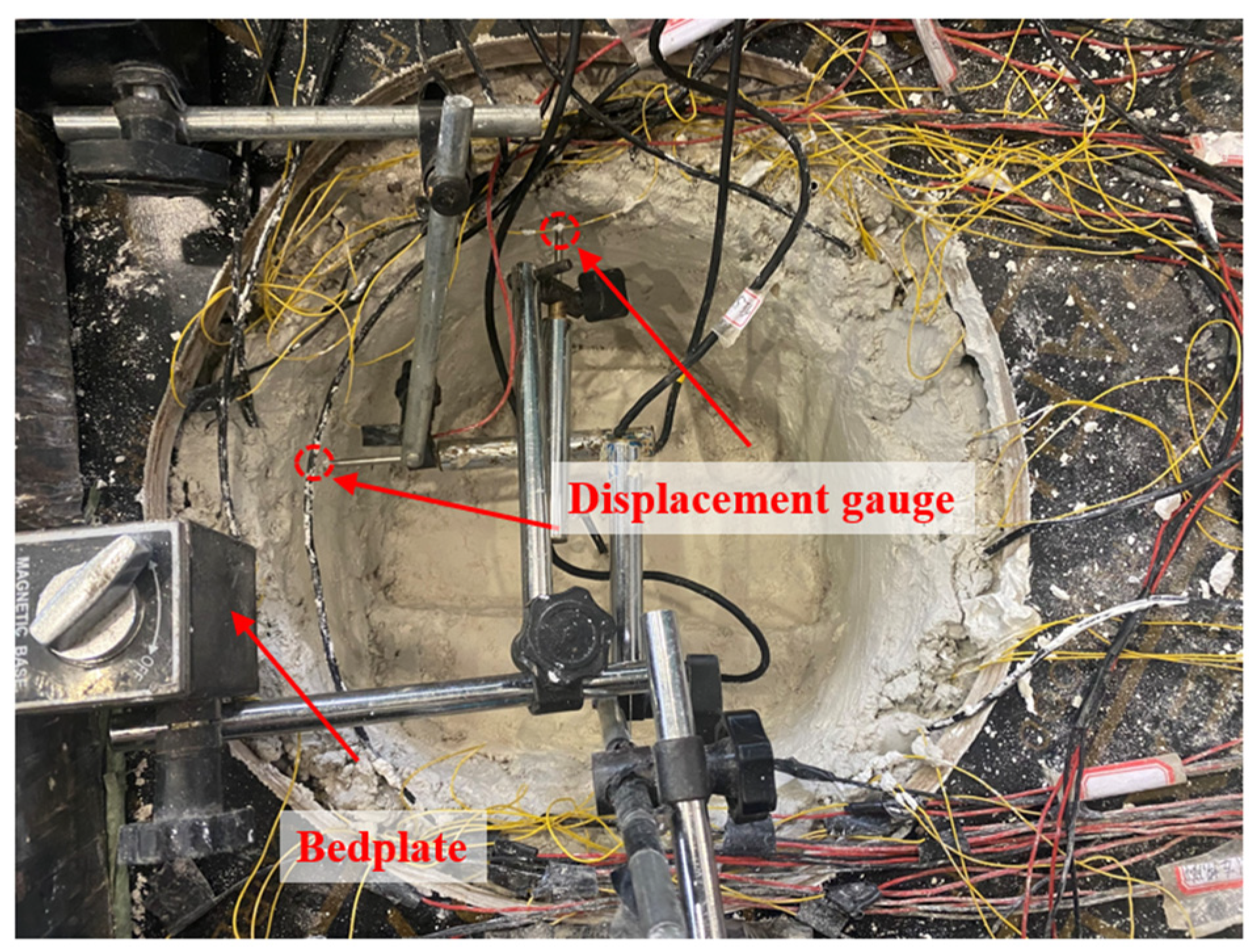
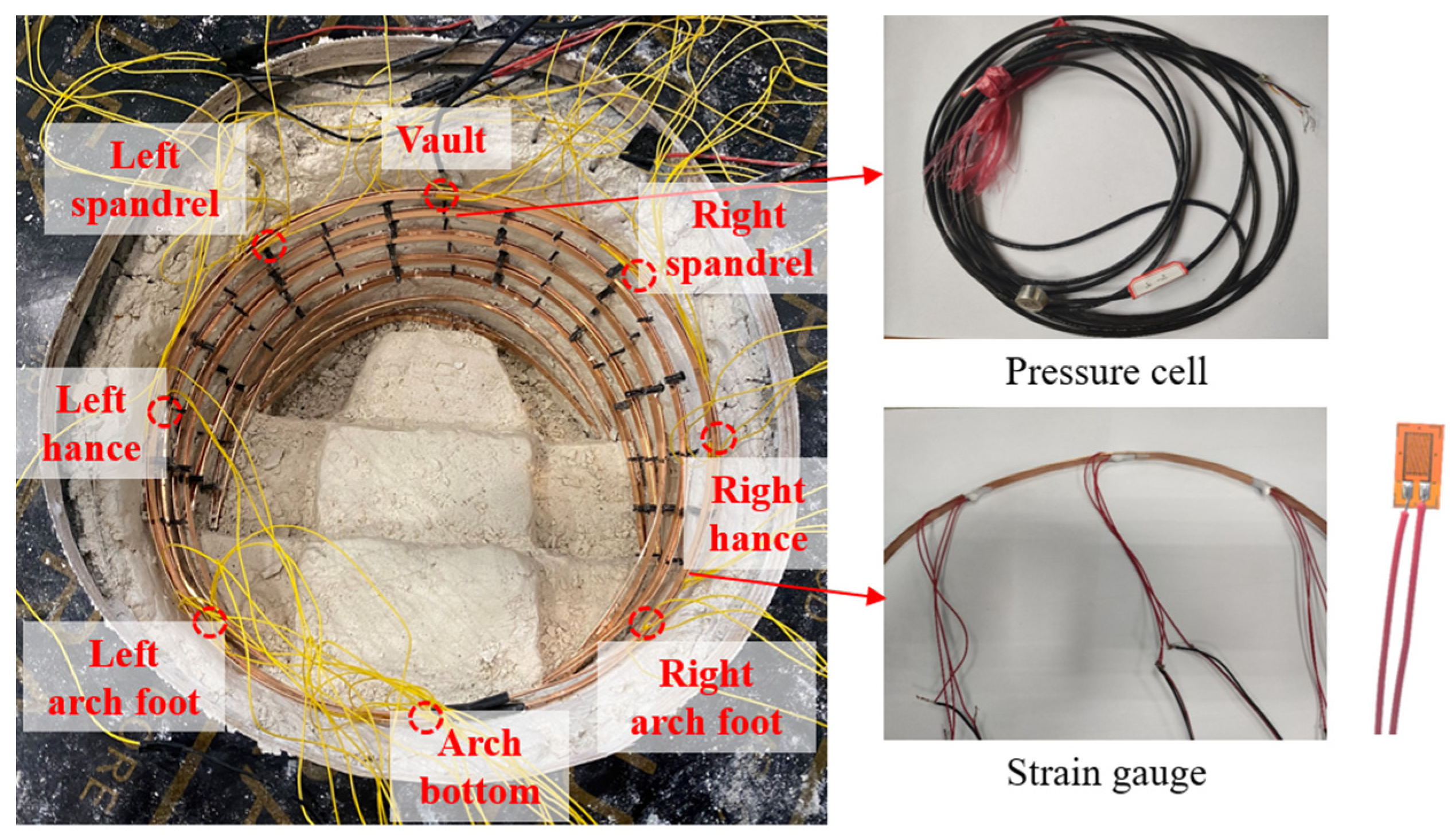
The monitoring system includes displacement monitoring and stress-strain monitoring, and it carries out multi-information monitoring and collection of the surrounding rock displacement deformation and stress evolution process during tunnel excavation. The vertical displacement and horizontal displacement of the tunnel are monitored by the monitoring surface near the lower step. The displacement monitoring device is composed of the base and the displacement meter (Figure 19). The earth pressure box is used to monitor the boundary load of surrounding rock and the contact pressure of the steel arch. Eight monitoring points are selected for the monitoring section, which includes the vault, left spandrel, right spandrel, left arch waist, right arch waist, left arch foot, right arch foot, and inverted arch (Figure 20). The surrounding rock pressure is measured using a miniature earth pressure cell arranged between the surrounding rock and the steel arch. Strain gauges are pasted between the first main support and the surrounding rock and between the first main support and the second main support to monitor the contact pressure between the tunnel’s surrounding rock pressure and the initial support. During the test, the strain on both sides of the copper sheet is monitored by the strain gauge, and the internal force of the steel arch is calculated to explore the differences caused by different excavation methods.
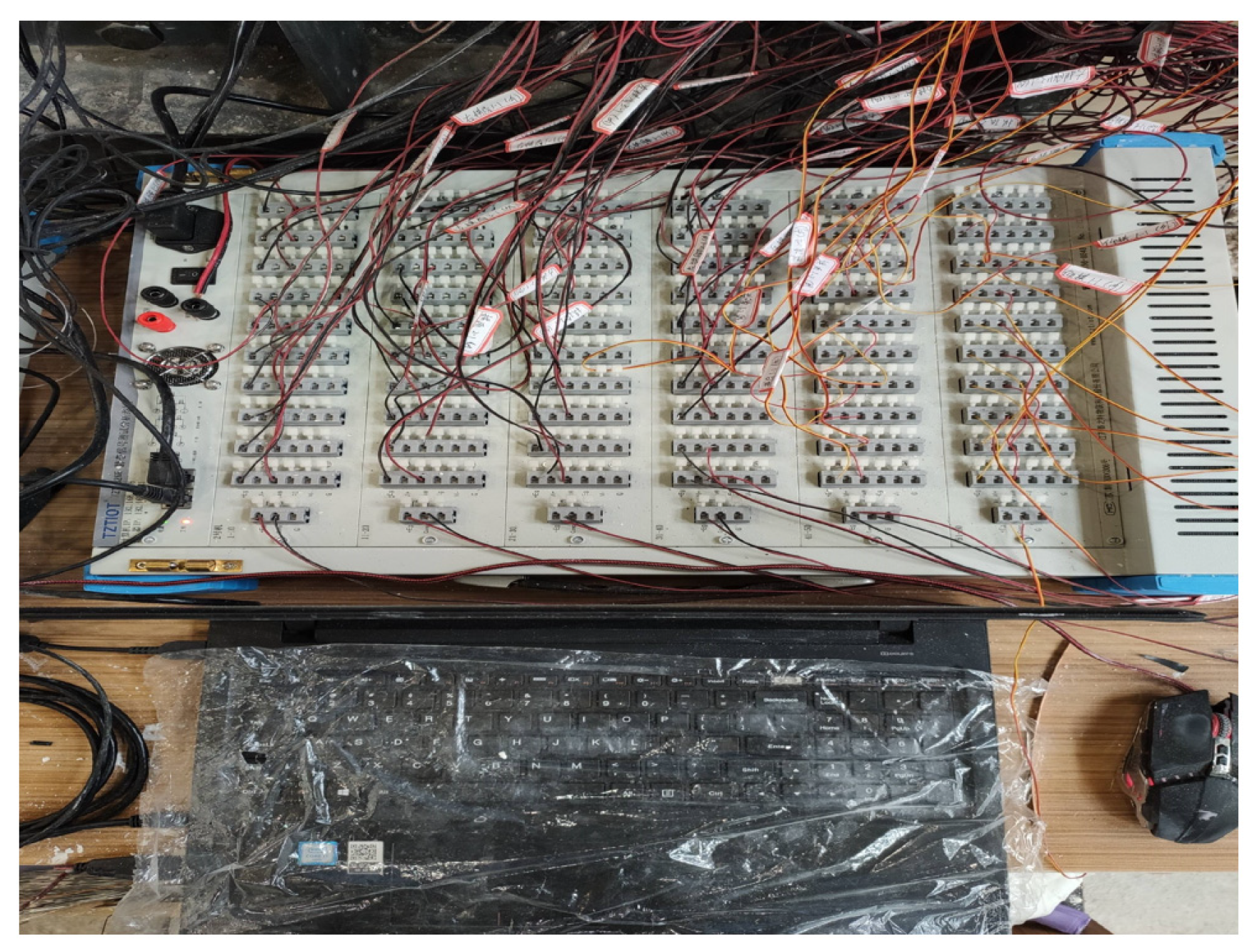
The displacement meter is used to monitor the displacement around the tunnel in real-time, and the static strain test system (Figure 21) is used to collect the monitoring data of the micro earth pressure box and the strain gauge. Among them, the strain gauge is connected by a 1/4 bridge, and a temperature compensation plate needs to be placed in every 10 channels. The miniature earth pressure box is connected by a full bridge without temperature compensation.

3.3. Experiment Results and Analysis

(1)
Tunnel deformation monitoring
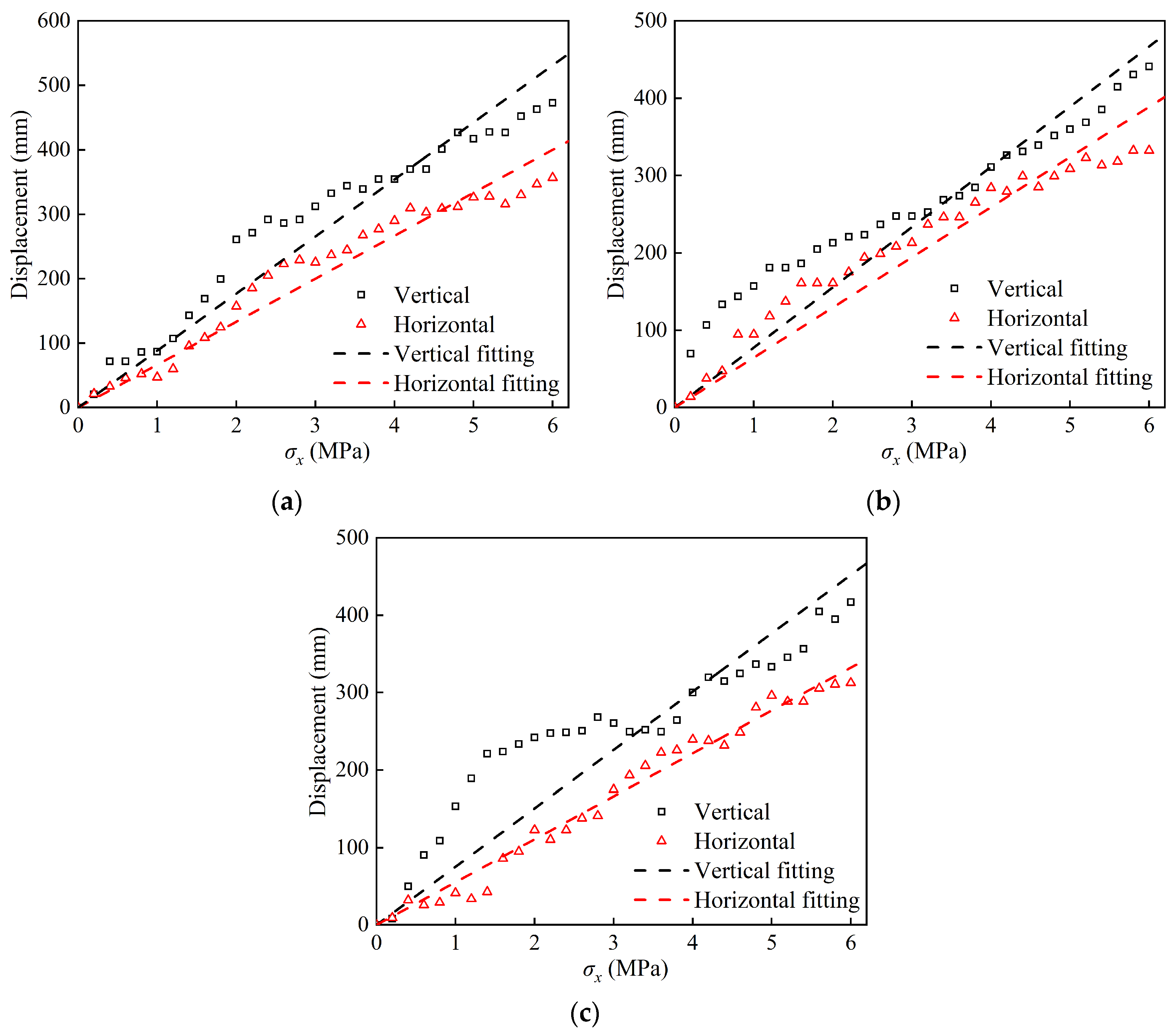
In order to explore the deformation characteristics of soft rock tunnels under different excavation methods and to make the results more intuitive, this paper converts the tunnel deformation results monitored by the displacement meter according to the length similarity ratio. We obtained the vertical and horizontal directions under different construction methods. The displacement diagram of the load change is also shown (Figure 22). It can be seen that under different excavation methods, the variation law of the displacement around the tunnel is close, which shows that the displacement around the tunnel gradually increases with the increase in load. The deformation around the tunnel is mainly vertical displacement, and the vertical displacement is 5.3~106.4% larger than the horizontal displacement. The confining pressure loading corresponds to the gradual increase in the stress release rate from 0. Combined with Figure 22, it can be seen that there is a certain linear relationship between the displacement of the tunnel and the applied load. The relationship between the two is highly fitted with the straight line, which further verifies the assumption that the displacement release rate is approximately equal to the stress release rate.
In order to more intuitively compare the deformation law of the tunnel surrounding under different excavation methods, the vertical displacement and horizontal displacement of the tunnel under each working condition are compared (Figure 23), and the final displacement value is shown in Table 9. It can be seen from the chart that the final value of vertical displacement is about 420~470 mm, and the final value of horizontal convergence is about 310~360 mm, which is close to the field measurement results (Figure 12). It can be seen that the model test results can better reflect the actual situation. The displacement around the tunnel is greatly affected by the excavation method. Compared with the three-bench excavation method, the final vertical displacements of the three-bench with reserved core soil method and the three-bench seven-step method are reduced by 6.7% and 11.8%, respectively, and the final horizontal displacements are reduced by 6.9% and 12.4%, respectively. It can be seen that the selection of appropriate excavation methods can effectively control the large deformation of the surrounding rock. Among the three excavation methods compared in this experiment, the three-bench seven-step method has the strongest ability to control tunnel deformation.
(2)
Analysis of tunnel pressure monitoring results
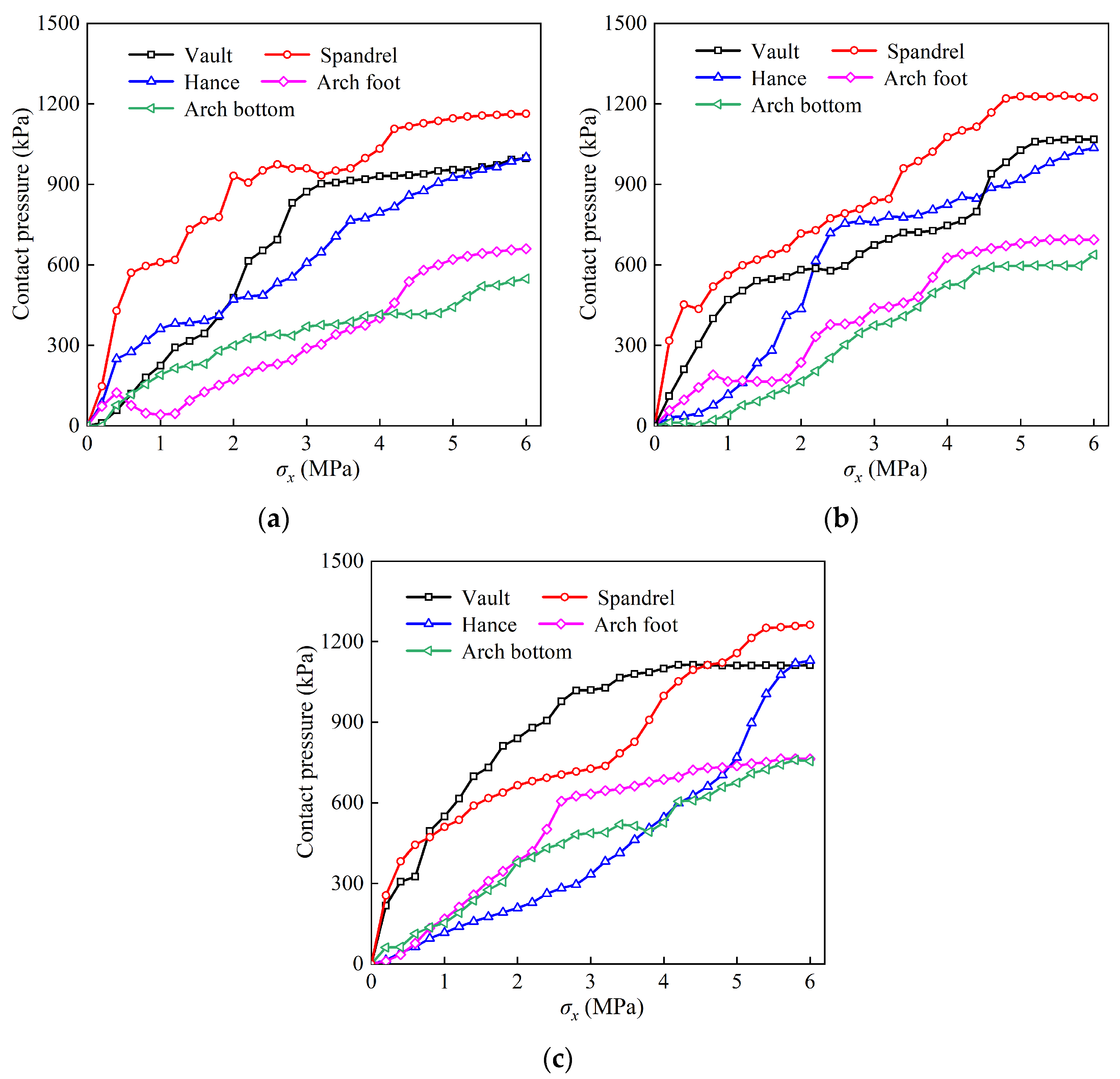
The earth pressure box is used to monitor the contact pressure of each monitoring point between the first layer of primary support and the surrounding rock and between the two layers of primary support. According to the stress similarity ratio, the change curve of pressure with load under different excavation methods is shown in Figure 24. Considering that the confining pressure loading and the model system are symmetrically distributed, only the monitoring data on one side of the supporting structure (vault, spandrel, haunch, arch foot, and arch bottom) are extracted for analysis.
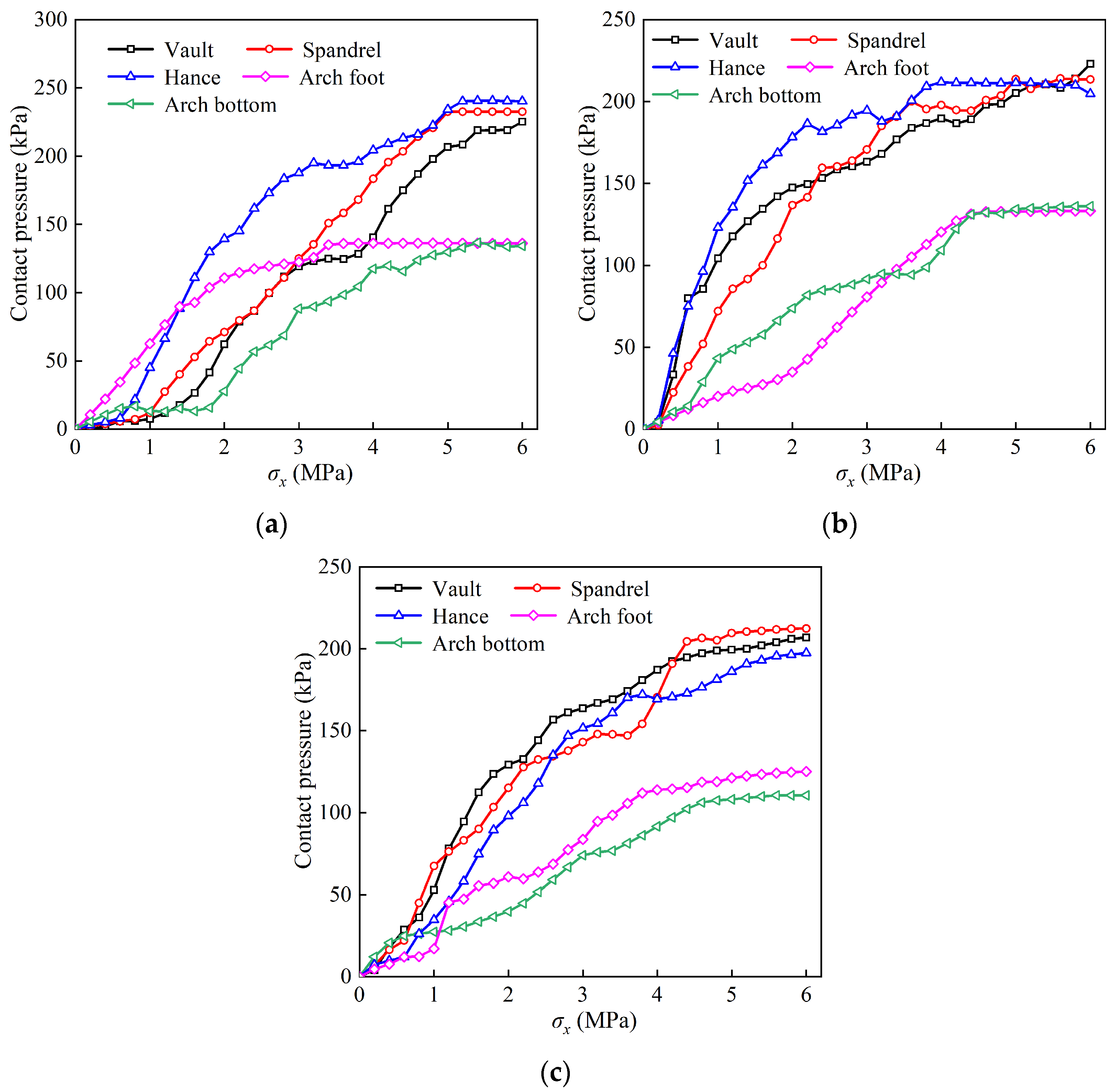
The test always keeps the lateral pressure coefficient λ = σ x σ y = 1.25 for bidirectional loading. It can also be seen from Figure 24 that the overall contact pressure is realized as spandrel > vault > haunch > arch foot > arch bottom. The load in the horizontal direction is large, and with the advancement of the test pressurization process, the stress release rate of the surrounding rock gradually increases. This part of the force is borne by the supporting structure, so the pressure between the initial support and the surrounding rock also increases gradually. Taking the three-bench seven-step method as an example, the contact stress between the vault and the arch foot is large in the early stage of load loading. When the test load gradually increases and approaches the measured ground stress, the contact stress between the arch shoulder and the arch waist increases rapidly. Finally, the contact stress of the arch shoulder is 498.5 kPa higher than that of the arch foot. Figure 25 shows the contact pressure between the first and second primary supports. It can be seen that the contact pressure between the arch foot and the arch bottom is small under different excavation methods, while the pressure at the vault, arch shoulder, and arch waist is relatively close.
In order to intuitively compare the contact pressure values under each excavation method, the final envelope diagram is drawn, as shown in Figure 26. The envelope diagram shows that the supporting structure is under overall pressure. From the quantitative point of view, the contact pressure of the first and second layers of the initial support is about 1100 kpa and 210 kpa. The pressure of the first layer of the initial support is much larger than that of the second layer, which is close to the field monitoring results, which further verifies the reliability of the model test.
From the comparison diagram of contact pressure, it can be seen that the distribution shape of the surrounding rock pressure under different excavation methods is relatively close. The pressure is mainly concentrated in the arch shoulder and arch waist, and the pressure at the arch foot and arch bottom is small. The first layer of the initial support of the three-bench method, the three-bench core soil, and the three-bench seven-step method all reached the maximum pressure at the arch shoulder, which were 1163.17 kPa, 1223.95 kPa, and 1262.93 kPa, respectively. The maximum pressure of the primary support of the second layer is distributed at the spandrel and haunch. The three excavation methods are 248.52 kPa, 222.96 kPa, and 216.83 kPa, respectively. It can be seen that the three-bench core soil method and the three-bench seven-step method are more complicated due to their processes. The stress release is more sufficient during the tunnel excavation process. The primary support structure of the first layer bears a greater load, while the load borne by the primary support of the second layer is reduced by 10.28% and 12.75%, respectively, compared with the three-bench method.
(3)
Analysis of internal force monitoring results of steel arch
In order to study the mechanical characteristics of the supporting structure of the soft rock tunnel under different excavation methods, the internal force of the supporting steel arch is monitored and analyzed. Due to the symmetry of the left and right sides of the model test, the strain values measured at the measuring points of one side (vault, arch shoulder, arch waist, arch foot, arch bottom) are extracted, and the axial force and bending moments of the copper sheet are calculated using Equation (5). The similarity ratio of the known axial force and bending moment is CN = 125,000, CM = 6,250,000, and the bending moment axial force of the actual steel arch is further calculated.
F = 1 2 E ( ε i n + ε o u t ) b h M = 1 12 E ( ε o u t ε i n ) b h 2
where b is the width of the copper strip; h is the thickness of the copper strip; E is the elastic modulus of the copper strip; ε i n is the measured strain value on the inner side of the copper strip; ε o u t is the measured strain value of the outer side of the copper strip.
At the same time, in order to further judge the safety of the steel arch and initial support, the safety factor of the steel arch is obtained according to Equation (6), and the bending moment axial force and safety factor of the steel arch under different excavation methods are sorted out in Table 10.
K a = R a / F A a ± M W a
where Ka is the safety factor of the steel arch, Ra is the ultimate strength of the steel arch, and Aa and Wa are the cross-sectional area and bending stiffness of the steel arch, individually.
According to Table 10, the minimum safety factors of the first layer of steel arch are 1.93, 1.49, and 1.20, respectively, and the minimum safety factors of the second layer of steel arch are 1.77, 2.03, and 2.19, respectively, under the three different excavation methods of the three-bench method, the three-bench with reserved core soil, and the three-bench seven-step method. It shows that the three-bench with reserved core soil and the three-bench seven-step method with more processes can make the first layer of initial support bear more force, release the surrounding rock pressure appropriately, and make the second layer of initial support in a safer situation.
Combined with the law of tunnel deformation and supporting structure stress obtained from the field measurement and model tests, it can be seen that the more the excavation steps, the smaller the vault settlement and the greater the stress of the supporting structure. This is because the values for stress release and stress redistribution in the surrounding rock are more and more load is distributed to the supporting structure, which leads to the phenomenon that the deformation of the tunnel body is small and the stress of the supporting structure is large. In order to reduce the deformation of the tunnel while controlling the stress of the supporting structure, prevent the lining from cracking and crushing due to excessive stress, and affect the engineering performance, it is necessary to evaluate the excavation method in combination with the deformation and stress and construction efficiency [35]. According to the above analysis, it can be concluded that the stress growth of the three-bench with reserved core soil is smaller than that of the three-bench excavation method, and the effect of controlling deformation is more obvious. Therefore, it is suggested that the three-bench excavation method with reserved core soil can be used in the subsequent tunnel construction.

4. Conclusions

Based on the typical soft rock tunnel project of the Dongmachang No. 1 Tunnel, this paper studies the excavation method of a soft rock tunnel based on stress release by combining field measurements with model tests, and we obtain the following main conclusions:
  • Tunnel excavation is essentially an accumulation process of stress release and displacement release. The two have a very close internal relationship. Combined with the field-measured data, the assumption that the stress release rate is approximately equal to the displacement release rate under certain conditions is verified.
  • A model test method for simulating tunnel excavation based on stress release is proposed: the confining pressure is loaded step by step from 0 to be consistent with the initial stress, which corresponds to the change process of the stress release rate in the surrounding rock. Combined with the field measurement results, the reliability of the test method is verified.
  • Model tests were carried out on tunnels with different excavation methods. The three-bench seven-step method had the best control effect on the deformation of surrounding rock, followed by the three-bench core soil method. The deformation of surrounding rock caused by the two excavation methods was reduced by 11.8~12.4% and 6.7–6.9%, respectively.
  • Through the monitoring of the contact pressure, steel arch, and the calculation of safety factor, it is shown that the pressure of the first layer of the three-bench seven-step method is 11.5% and 14.6% higher than that of the three-bench core soil method and the three-bench method, respectively, and the pressure of the second layer is reduced by 12.75% and 2.7%, respectively. The more excavation steps in the construction method, the more sufficient the stress release of the surrounding rock, which can give full play to the supporting role of the primary support and improve the safety of the secondary support. Based on the actual engineering and test results, it is recommended that the three-bench core soil method is more reasonable for the construction of a high-stress soft rock tunnel through an active fault zone.

Author Contributions

Conceptualization, C.H.; Methodology, H.K.; Software, J.N. and F.L.; Validation, J.N., H.K. and F.L.; Formal analysis, C.H.; Resources, C.H. and W.Y.; Data curation, J.N. and F.L.; Writing—original draft, J.N.; Writing—review & editing, H.K. and W.Y.; Supervision, W.Y.; Funding acquisition, C.H. All authors have read and agreed to the published version of the manuscript.

Funding

This research was supported by the Science Foundation for Distinguished Young Scholars of Sichuan Province (No. 2022JDJQ0018) and the CSCEC Technology R & D Plan of China (No. CSCEC-2021-Z-26).

Institutional Review Board Statement

Not applicable.

Informed Consent Statement

Not applicable.

Data Availability Statement

The data presented in this study are available in the article.

Conflicts of Interest

The authors declare no conflict of interest.

References

  1. Xu, P.; Peng, P.; Wei, R.-H.; Zhang, Z.-Q. Model test of the mechanism underpinning water-and-mud inrush disasters during tunnel excavation in sandstone and slate interbedded Presinian strata. J. Zhejiang Univ. Sci. A 2022, 23, 882–899. [Google Scholar] [CrossRef]
  2. Chen, Z.Q.; He, C.; Xu, G.W.; Ma, G.; Wu, D. A case study on the asymmetric deformation characteristics and mechanical behavior of deep-buried tunnel in phyllite. Rock Mech. Rock Eng. 2019, 52, 4527–4545. [Google Scholar] [CrossRef]
  3. Liu, W.W.; Chen, J.X.; Luo, Y.B.; Chen, L.; Shi, Z.; Wu, Y. Deformation behaviors and mechanical mechanisms of double primary linings for large-span tunnels in squeezing rock: A case study. Rock Mech. Rock Eng. 2021, 54, 2291–2310. [Google Scholar] [CrossRef]
  4. Sun, X.M.; Zhao, C.W.; Tao, Z.G.; Kang, H.; He, M. Failure mechanism and control technology of large deformation for muzhailing tunnel in stratified rock masses. Bull. Eng. Geol. Environ. 2021, 80, 4731–4750. [Google Scholar] [CrossRef]
  5. Xu, G.W.; He, C.; Chen, Z.Q.; Yang, Q. Transversely isotropic creep behavior of phyllite and its influence on the long-term safety of the secondary lining of tunnels. Eng. Geol. 2020, 278, 105834. [Google Scholar] [CrossRef]
  6. Xia, C.; Liu, Z.; Zhou, C.; Zhang, L. A Meso/Macroscale Theoretical Model for Investigating the Large Deformation of Soft Rock Tunnels Considering Creep and Anisotropic Effects. Rock Mech. Rock Eng. 2023, 56, 4901–4922. [Google Scholar] [CrossRef]
  7. Xin, J.; Jiang, Q.; Li, S.; Chen, P.; Zhao, H. Fracturing and energy evolution of rock around prefabricated rectangular and circular tunnels under shearing load: A comparative analysis. Rock Mech. Rock Eng. 2023, 56, 9057–9084. [Google Scholar] [CrossRef]
  8. Ding, W.Q.; Tan, S.; Zhu, R.Q.; Jiang, H.; Zhang, Q. Study on the Damage Process and Numerical Simulation of Tunnel Excavation in Water-Rich Soft Rock. Appl. Sci. 2021, 11, 8906. [Google Scholar] [CrossRef]
  9. Xu, C.; Xia, C.C.; Han, C.L. Elastoplastic Solutions for Deep Tunnel Excavation in Weak Rocks with High Geostress Considering Different Stress Release Measures. Int. J. Appl. Mech. 2022, 14, 2250077. [Google Scholar] [CrossRef]
  10. Qiu, J.T.; Shen, Y.S.; Zhang, X.; Zhang, Y.; Gan, Y.; Zhou, X. Simplified Method for Predicting Time-Dependent Behavior of Deep-Buried Tunnel Considering Tunnel Excavation Rate and Stress Release Effects. Int. J. Appl. Mech. 2022, 14, 2250043. [Google Scholar] [CrossRef]
  11. Zhou, S.; Li, L.P.; An, Z.M.; Liu, H.; Yang, G.; Zhou, P. Stress-Release Law and Deformation Characteristics of Large-Span Tunnel Excavated with Semi Central Diaphragm Method. KSCE J. Civ. Eng. 2021, 25, 2275–2284. [Google Scholar] [CrossRef]
  12. Neuner, M.; Schreter, M.; Gamnitzer, P.; Hofstetter, G. On discrepancies between time-dependent nonlinear 3D and 2D finite element simulations of deep tunnel advance: A numerical study on the Brenner Base Tunnel. Comput. Geotech. 2020, 119, 103355. [Google Scholar] [CrossRef]
  13. He, M.C.; Sui, Q.R.; Li, M.N.; Wang, Z.; Tao, Z. Compensation excavation method control for large deformation disaster of mountain soft rock tunnel. Int. J. Min. Sci. Technol. 2022, 32, 951–963. [Google Scholar] [CrossRef]
  14. Fan, B.H.; Lai, X.J.; Hou, D.D. The Bench Method Numerical Simulation of Soft Rock Tunnel. Appl. Mech. Mater. 2013, 2733, 949–953. [Google Scholar] [CrossRef]
  15. Wang, W.; Hu, M.J.; Zhang, H.W.; Zhang, X. Conversion Timing of Tunnel Excavation Methods in Upper-Soft and Lower-Hard Stratum Based on Displacement Direction Angle Theory: Case Study. Int. J. Geomech. 2019, 19, 05019003. [Google Scholar] [CrossRef]
  16. Zhan, Q.J.; Muhammad, S.N.; Zheng, X.G.; Xue, Z.; He, Y. Instability mechanism and coupling support technology of full section strong convergence roadway with a depth of 1350 m. Eng. Fail. Anal. 2022, 139, 106374. [Google Scholar] [CrossRef]
  17. Lyu, X.Z.; Zhao, Z.H.; Ma, Q.; Wang, X.; Gao, X. 2D Semimodel of Full-Section Anchorage in Thick Soft Rock Roadway. Shock. Vib. 2018, 2018, 9853853. [Google Scholar] [CrossRef]
  18. Barla, G. Full-face excavation of large tunnels in difficult conditions. J. Rock Mech. Geotech. Eng. 2016, 8, 294–303. [Google Scholar] [CrossRef]
  19. Cui, G.Y.; Xiong, Y.; Wang, D.Y. Field test study on large deformation control of strongly weathered carbonaceous slate tunnel in high geostress. In Proceedings of the Institution of Civil Engineers—Transport; Thomas Telford Ltd.: London, UK, 2023; pp. 1–29. [Google Scholar]
  20. Cui, G.Y.; Chen, Q.L. Research on large deformation control technology of highly weathered carbonaceous slate tunnel. Appl. Rheol. 2023, 33, 20220152. [Google Scholar] [CrossRef]
  21. Fang, Z.C.; Zhu, Z.G.; Chen, X.Y. Research on construction method and deformation control technology of high ground stress interbedded soft rock tunnel. J. Intell. Fuzzy Syst. 2021, 40, 6175–6183. [Google Scholar] [CrossRef]
  22. Feng, J.; Yang, H.J.; Zhang, Y. A Study on Excavation Characteristics of Tunnel with Upper-Soft Lower-Hard Stratum. Geofluids 2022, 2022, 1094281. [Google Scholar] [CrossRef]
  23. Jiang, X.M.; Hou, L.L.; Shang, S.P.; Xu, L.; Yu, H. Physical Modeling of a Shallow-Buried Metro Tunnel in the Soft Loess Layer Using Similarity Theory. Adv. Civ. Eng. 2022, 2022, 5587116. [Google Scholar] [CrossRef]
  24. He, M.C.; Wang, Q. Excavation compensation method and key technology for surrounding rock control. Eng. Geol. 2022, 307, 106784. [Google Scholar] [CrossRef]
  25. Kou, H.; He, C.; Wu, F.; Yang, W.; Wang, B.; Xiao, L. Inversion Analysis of Initial Geostress Field of Highway Tunnel Considering Influence of Strike-slip Fault Activity. China J. Highw. Transp. 2022, 35, 321–330. [Google Scholar]
  26. Zhao, K.; Janutolo, M.; Banla, G. A Completely 3D Model for the Simulation of Mechanized Tunnel Excavation. Rock Mech. Rock Eng. 2012, 45, 475–497. [Google Scholar] [CrossRef]
  27. Sun, Z.Y.; Zhang, D.L.; Ao, L. Model test and numerical analysis for the face failure mechanism of large cross-section tunnels under different ground conditions. J. Tunn. Undergr. Space Technol. Inc. Trenchless Technol. Res. 2022, 130, 104735. [Google Scholar] [CrossRef]
  28. Zhang, X.Y.; Zhang, L.W.; Wu, J.; Fu, H.; Dian, L.Y. Tunnel stability analysis of coral reef limestone stratum in ocean engineering. Ocean. Eng. 2022, 265, 112636. [Google Scholar] [CrossRef]
  29. Heidarzadeh, H.; Kamgar, R. Evaluation of the Importance of Gradually Releasing Stress around Excavation Regions in Soil Media and the Effect of Liners Installation Time on Tunneling. Geotech. Geol. Eng. Int. J. 2020, 38, 2213–2225. [Google Scholar] [CrossRef]
  30. Cantieni, L.; Anagnostou, G. On a paradox of elasto-plastic tunnel analysis. Rock Mech. Rock Eng. 2011, 44, 129–147. [Google Scholar] [CrossRef]
  31. Manh, H.T.; Sulem, J.; Subrin, D. Progressive degradation of rock properties and time-dependent behavior of deep tunnels. Acta Geotech. 2016, 11, 693–711. [Google Scholar] [CrossRef]
  32. Zhang, H.J.; Zhang, T.P.; Wang, K.F.; Xu, Y.; Wang, W.; Wang, Q.; Zhang, G. Numerical experimental study on deformation characteristics of tunnel face of metro tunnel in overlying water-rich sand layer. J. Disaster Prev. Mitig. Eng. 2023, 1–11. [Google Scholar] [CrossRef]
  33. Huang, J.; Chen, S.H.; Liu, M.L.; Li, K.P. Physical model test and numerical simulation study of cumulative damage to deep tunnel surrounding rock under cyclic blasting load. Int. J. Damage Mech. 2023, 32, 161–184. [Google Scholar] [CrossRef]
  34. Du, C.F.; Zhou, C.B.; Jiang, N.; Huang, Y. Structural Stability Monitoring of Model Test on Highway Tunnel with Lining Backside Voids Using Dynamic and Static Strain Testing Sensors. Sensors 2023, 23, 1403. [Google Scholar] [CrossRef] [PubMed]
  35. Rosso, M.M.; Marasco, G.; Aiello, S.; Aloisio, A.; Chiaia, B.; Marano, G.C. Convolutional networks and transformers for intelligent road tunnel investigations. Comput. Struct. 2023, 275, 106918. [Google Scholar] [CrossRef]
Figure 1. Longitudinal profile of Dongmachang I tunnel on the Huaping-Lijiang highway.
Applsci 14 00668 g001
Figure 2. Tunnel site schematic diagram.
Applsci 14 00668 g002
Figure 3. Typical large deformation diseases in engineering sites: (a) Initially branch the block peeling off; (b) inverted arch uplift.
Applsci 14 00668 g003
Figure 4. Inversion results of the ground stress field in the tunnel site area [25].
Applsci 14 00668 g004
Figure 5. Relationship between tunnel deformation and excavation face position.
Applsci 14 00668 g005
Figure 6. Displacement measuring point layout diagram.
Applsci 14 00668 g006
Figure 7. Field deformation monitoring.
Applsci 14 00668 g007
Figure 8. Monitoring data of K71 + 882: (a) Displacement; (b) displacement rate.
Applsci 14 00668 g008
Figure 9. Relationship between stress release and excavation face position.
Applsci 14 00668 g009
Figure 10. Pressure cell installation.
Applsci 14 00668 g010
Figure 11. Stress measuring point layout diagram.
Applsci 14 00668 g011
Figure 12. K71 + 882 monitoring surface time-stress curve.
Applsci 14 00668 g012
Figure 13. The relationship between the stress/displacement release coefficient and excavation face position.
Applsci 14 00668 g013
Figure 14. Traditional tunnel model test device [28].
Applsci 14 00668 g014
Figure 15. Horizontal loading test device: where η is the stress release coefficient, the σx0 is the initial horizontal principal stress, and the σy0 is the initial vertical principal stress.
Applsci 14 00668 g015
Figure 16. Each support in the model test.
Applsci 14 00668 g016
Figure 17. Test filling process.
Applsci 14 00668 g017
Figure 18. Tunnel model excavation method: (a) Three-bench; (b) three-bench with reserved core soil; (c) three-bench seven-step.
Applsci 14 00668 g018
Figure 19. Layout of displacement monitoring.
Applsci 14 00668 g019
Figure 20. Layout of the stress monitoring.
Applsci 14 00668 g020
Figure 21. Data acquisition system.
Applsci 14 00668 g021
Figure 22. Displacement changes with load under different excavation methods: (a) Three-bench; (b) three-bench with reserved core soil; (c) three-bench seven-step.
Applsci 14 00668 g022
Figure 23. Displacement comparison using different construction methods: (a) Vertical displacement; (b) horizontal displacement.
Applsci 14 00668 g023
Figure 24. Contact pressure of the first primary support with different excavation methods: (a) Three-bench; (b) three-bench with reserved core soil; (c) three-bench seven-step.
Applsci 14 00668 g024
Figure 25. Contact pressure of the second primary support with different excavation methods: (a) Three-bench; (b) three-bench reserve core soil; (c) three-bench seven-step.
Applsci 14 00668 g025
Figure 26. Comparison of contact pressure with different middle bench lengths: (a) The first primary support; (b) the second primary support.
Applsci 14 00668 g026
Table 1. Initial stress field of section K71 + 882.
Maximum Horizontal Principal Stress
(MPa)
Minimum Horizontal Principal Stress
(MPa)
Vertical Stress
(MPa)
10.549.648.78
Table 2. The similarity ratio of the physical quantities between prototype and model.
Physical QuantitySimilarity Scale RelationsSimilarity Ratio (Prototype:Model)
LengthCL50:1
Unit weightCγ1:1
Internal friction angle/strainCφ = Cε1:1
Stress/elastic modulus/cohesion/compressive StrengthCσ = CE = Cc = Cσc = CγCl50:1
Axial forceCN125,000:1
Bending momentCM6,250,000:1
Table 3. Mechanical parameters of the surrounding rock mass.
TypeElastic Modulus E
(MPa)
Unit Weight γ
(kN·m−3)
Poisson’s RatioCohesion c
(kPa)
Internal Friction Angle φ
(°)
Prototype1200200.48027
Model240.40.41.627
Table 4. Surrounding rock with similar material ratio.
Blanc FixeQuartz SandGessoTalc PowderWater
0.470.140.100.060.23
Table 5. Mechanical parameters of the advanced pipes.
TypeLength (m)Diameter (mm)Spacing Ring (cm)Elastic Modulus E
(MPa)
Prototype97640210
Model0.184.52.5194
Table 6. Mechanical parameters of the anchor bar.
TypeLength (m)Diameter (mm)Spacing Ring (cm)Elastic Modulus E
(MPa)
Prototype4/6/925/51/1081.2210
Model0.08/0.12/0.182/4/40.0240.158
Table 7. Model of the steel arch and size of the copper sheet.
ModelTypeElastic Modulus
(GPa)
Inertia Moment
(cm4)
Spacing
(cm)
Width × Thickness
(mm)
I25bPrototype210528060
Model1053.41 × 10−51.28 × 0.8
I22bPrototype210357060
Model1052.13 × 10−51.25 × 0.8
Table 8. The physical parameters of the shotcrete.
TypeUnit Weight
(kN·m−3)
Elastic Modulus
(GPa)
Poisson’s Ratio
Prototype2226,0000.2
Model225200.2
Table 9. Model test tunnel circumferential displacement under different construction methods.
Excavation MethodsVertical Displacement (mm)Horizontal Displacement (mm)
Three-bench seven-step417.17312.66
Three-bench reserve core soil441.28332.55
Three-bench472.98357.12
Table 10. Comparison of the internal force and safety factor for the primary support with different middle bench lengths.
Supporting StructureMonitoring PositionThree-BenchThree-Bench with Reserved Core SoilThree-Bench Seven-Step
Force
(kN)
Moment
(kN·m)
Safety FactorForce
(kN)
Moment
(kN·m)
Safety FactorForce
(kN)
Moment
(kN·m)
Safety Factor
The first primary supportVault286.723.71.99311.933.41.49351.134.61.42
Spandrel236.824.62.01325.8271.75461.439.51.20
Hance268.925.11.93341.627.81.69455.534.41.34
Arch foot189.512.63.54233.719.52.42283.322.52.08
Arch bottom187.314.93.14219.918.42.57233.621.92.22
The second primary supportVault29830.21.7727826.22.03270.216.62.78
Spandrel267.528.61.8923820.42.51187.629.42.19
Hance289.129.11.83239.116.92.86201.320.12.65
Arch foot207.418.52.80187.114.13.50152.811.84.21
Arch bottom184.416.23.18134.412.94.0987.410.35.37
Disclaimer/Publisher’s Note: The statements, opinions and data contained in all publications are solely those of the individual author(s) and contributor(s) and not of MDPI and/or the editor(s). MDPI and/or the editor(s) disclaim responsibility for any injury to people or property resulting from any ideas, methods, instructions or products referred to in the content.