Abstract
A heavy-duty engine is homologated in a test cell. However, starting with Euro VI regulation, the in-service conformity is controlled with the engine installed in the vehicle using portable emission measurement systems (PEMS). In Europe, the application of solid particle number (SPN) PEMS started in 2021 for compression ignition (diesel) vehicles and in 2023 for positive ignition vehicles, thus including those operating with compressed natural gas (CNG). Even though today only particles with sizes > 23 nm are regulated, the Euro 7 proposal includes particles > 10 nm. There are not many studies on the accuracy of the SPN PEMS, especially for heavy-duty applications. In this study, PEMS measuring > 23 and >10 nm from two instrument manufacturers were compared with laboratory-grade instruments. The particle detector of one PEMS was a condensation particle counter (CPC), and of the other a the diffusion charger (DC). The results showed the robustness and good accuracy (40% or 1 × 10¹¹ #/kWh) of the PEMS for ambient temperatures from −7 °C to 35 °C, active regeneration events, different fuels (Diesel B7, HVO, and CNG), different test cycles, cold start or hot engine operations, and high exhaust gas humidity content. Nevertheless, for the DC-based PEMS, sensitivity to pre-charged urea particles was identified, and for the CPC-based PEMS, sensitivity to pressure changes with one vehicle was nnoticed. Nevertheless, the results of this study confirm that the PEMS are accurate enough to measure even the stricter Euro 7 limits.
1. Introduction
The road freight transportation sector is central in the European Union (EU) for the economy and environment [1,2]. Exhaust emissions from vehicles have decreased significantly over the years due to the implementation of effective aftertreatment devices in response to the limits imposed by the different regulations [3,4,5]. Traditionally, for heavy-duty vehicles, engines are type-approved in test cells. This had the difficulty of removing the engine from in-use vehicles to control compliance over the lifetime of the engines. A big step forward was the introduction of portable emission measurement systems (PEMS), which made measurements of emissions possible without removing the engine from the vehicle [6]. In Europe, PEMS for gaseous pollutants were introduced with Euro VI regulation (Commission Regulation (EU) 582/2011). Solid particle number (SPN) limits for particles larger than 23 nm for the type approval of engines were applied to compression ignition (diesel) engines in 2013 (Euro VI) and to positive ignition engines in 2014. SPN PEMS testing was added with Euro VI step E (Commission Regulation (EU) 2019/1939) in 2021 for CI engines and 2023 for PI engines. A margin of 0.63 is applicable to on-road tests to take into account the SPN PEMS measurement uncertainty. China has also introduced PEMS on-road testing for heavy-duty vehicles with China VIb; India will introduce it in the near future [7,8,9].
The European Commission’s Euro 7 proposal in November 2022 [10] and the final agreed text [11] include stricter limits with a reduction of the lower 23 nm size to 10 nm. This proposal has triggered discussions about situations where a large number of sub-23 nm particles appear. For example, engines fueled with compressed natural gas (CNG) are considered soot-free due to the low particulate matter mass they produce. However, many studies have shown that they are not SPN-free [12,13,14,15], and most importantly, the particle concentration below 23 nm can be high [16,17,18,19]. Diesel vehicles have the issue of sub-23 nm particles produced during urea injection [17]. Urea dosing is used to reduce NOx emissions, but in some cases, “solid” particles appear downstream of the selective catalytic reduction for the NOx system [20]. Studies have found higher emissions of about +1 × 10¹¹ #/kWh by lowering the size from 23 nm to 10 nm [21,22,23]. These particles are believed to be ammonium salts [24,25] or urea decomposition products (cyanuric acid and ammelide) [21,26,27,28]. A recent study also found that different urea solutions can result in different increases in the SPN concentration for the same engine, and it was attributed to their different metallic element contents [29].
A different topic, but also of importance for the lower proposed limits, is the measurement uncertainty of SPN PEMS [30]. While a margin of 0.63 (i.e., uncertainty 63%) is applicable for Euro VI testing, the Euro 7 proposal limits do not have any additional margin, but an approximately 40% uncertainty has been considered. The SPN instruments consist of a diluter, a heated section at ≥300 °C, and a particle detector [8]. The combined systems must have a detection efficiency of around 40% at 23 nm. At approximately 50–100 nm, the efficiency has to be 100% (±30%), and at 200 nm, it is ≤200%. For 10 nm measurements, the heated section has to include a catalytic stripper to oxidize volatiles, and the efficiency of 50% is at 15 nm. At larger sizes (50–100 nm), the efficiency is 100% (±15%). Two technologies are used as particle detectors: condensation particle counters (CPCs) (e.g., [31]) or diffusion chargers (DCs) (e.g., [32]). CPCs, in general, are considered more accurate because they count each particle after it has grown to the micrometer range in a supersaturated vapor region. DCs charge the particles in a corona charger and then measure the charge of the particles (or the escaping charge) with an electrometer. The charging efficiency depends on the size of the particles [33], so there is some additional uncertainty when converting current to particle number concentration. There are also some concerns regarding the lower detection limit of DC-based PEMS for low-emitting vehicles.
The assessment of PEMS for heavy-duty applications is limited [34], in particular for the 10 nm systems. The reason is that the 23 nm SPN PEMS testing has been required for a few years (2021), and the 10 nm SPN PEMS are not regulated yet. Thus, until recently, researchers have been using different techniques to measure on-board the vehicle not only for heavy-duty vehicles (e.g., [35,36,37,38]) but also for light-duty ones (e.g., [39,40]). While research studies with SPN PEMS exist (e.g., [41,42]), the assessment of PEMS is limited. One of the few studies with heavy-duty engines and with three PEMS manufacturers found differences to the 10 nm reference instruments of 50% [22]. Studies with light-duty vehicles have found differences of 50% for four 10 nm instrument manufacturers and a wide range of engine technologies [43]. But higher differences have also been reported in the past. For example, 23 nm diffusion charger-based systems had differences of 70–100% [44,45]. One of the reasons was the sensitivity of diffusion chargers to existing charges on the particles [46]. Pre-chargers or electrofilters were found to be efficient in neutralizing or removing these particles [46]. This technology has not been tested since then.
There are also some other boundary conditions that need further testing. For example, active regeneration events, different ambient temperatures, and different fuels such as hydrotreated vegetable oil (HVO) and CNG have received high attention over the past few years [47,48,49,50,51]. We are not aware of any other study assessing PEMS for heavy-duty vehicles. A plausible explanation is that there are no “validation” test requirements as in the light vehicle regulation. For light-duty vehicles, the PEMS can be compared with the laboratory-grade equipment on the chassis dynamometer—the so-called “validation”. For heavy duty, such provisions are not foreseen during the type approval of the engine.
Based on this background, our aim is to assess SPN PEMS with various heavy-duty vehicles in different conditions. Although the focus is on the future 10 nm systems, results with the 23 nm systems are also given. Compared to previous PEMS assessment studies with light-duty [43] and heavy-duty vehicles [22], we extend with more engines and boundary conditions. The study covers conditions from −7 to 35 °C for CNG and diesel vehicles with market (B7) or HVO fuel operating in real-world driving conditions. The results of this study give uncertainty estimations of the particle number measurements.
2. Materials and Methods
The assessment of the 10 nm instruments was done at the vehicle emissions laboratory (no. 7) of the Joint Research Centre (JRC) in Ispra, Italy. Four heavy-duty vehicles were tested with various cycles at ambient temperatures of −7 °C, 22 °C, and/or 35 °C (Table 1). The diesel-fueled vehicles are abbreviated as D1-D3, while the CNG-fueled vehicle is abbreviated as CNG. The Diesel Fuel B7 was the market fuel with a maximum 7% content of fatty acid methyl ester (FAME), but the HVO fuel was purchased. The CNG was a market quality of unknown composition. The commercial natural gas of the area typically contains 85–96% methane; heavier hydrocarbons, such as ethane, propane, and butane; and inert diluents, such as N2 and CO2. The tests were parts of various projects, and thus, the instruments were operated by the technical staff of the laboratory. As they were not dedicated tests for the 10 nm instruments, they can be considered representative of the current situation and not optimized cases for the PEMS.

Table 1.
Overview of vehicles and instrumentation.
The test cycles included the worldwide harmonized heavy-duty vehicles cycle (WHVC), in-service conformity like cycles (Regulation (EU) 582/2011 and 2019/1939), and verification testing procedure (VTP) cycles (Commission Regulation (EU) 2017/2400); the last two are abbreviated as real-world cycles (RWC). As the study focused on comparing instruments, the integrated emissions for the period of interest were calculated. For all cycles starting with the engine at ambient temperature, the first 900 s were evaluated separately and are abbreviated as “cold” engine start. The remaining of the cycle (duration 5500–11,000 s after the 900 s, depending on the cycle and vehicle) was then evaluated separately and considered “hot” part. Similarly, all tests in which the engine coolant was not at ambient temperature (usually >70 °C) at the engine starting (WHVC hot and some RWC) are considered “hot” cycles, and the integration was done from the beginning of the cycle. Thus, the analysis did not follow the Euro VI step E methodology with moving average windows [52], considering cold start after the coolant temperature has reached 30 °C, hot emissions after the coolant temperature has reached 70 °C, and weighing cold and hot start emissions at 14% and 86%, respectively.
Figure 1 gives an overview of the setup and the instruments that were used. The particle number instruments were reference laboratory-grade instruments and portable emission measurement systems (PEMS). As reference instruments, two advanced particle counters (APCs) from AVL (Graz, Austria) were used, both fulfilling the SPN requirements of the heavy-duty regulation (UNECE Regulation 49). One was connected to the dilution tunnel with a constant volume sampler (CVS) and one at the tailpipe. Both could measure both >23 and >10 nm particles. In current regulations (UNECE Regulation 49), the reference instrument is connected to the dilution tunnel (or proportional partial flow system). Recently, a technical regulation gave the possibility to connect directly at the tailpipe with equivalent results [53].
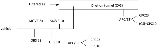
Figure 1.
Experimental setup. Not all instruments were available for all tests. OBS and MOVE are CPC- and DC-based portable emissions measurement systems (PEMS), respectively (see Table 1). APC = advanced particle counter; CPC = condensation particle counter; CS = catalytic stripper; DC = diffusion charger; CVS = constant volume sampler; ET = evaporation tube.
The instrument at the dilution tunnel consisted of a hot diluter (150 °C), an evaporation tube (350 °C), a secondary diluter at ambient temperature, and two butanol-based condensation particle counters (CPCs) with 50% detection efficiencies at approximately 23 nm and 10 nm, respectively. CPCs optically count particles after growing them to micrometer size in a super-saturated environment of the working fluid (butanol in this case). For the tests with the D1 vehicle, a catalytic stripper (350 °C) from Catalytic Instruments (Rosenheim, Germany) was added to minimize volatile artifacts. Based on the manufacturer’s calibration certificate, due to additional diffusion and thermophoretic losses in the catalytic stripper, a 1.4 correction factor was applied for these tests. The correction gives good results when the particle size distribution has a geometric mean diameter larger than 30 nm. As it will be shown in the Results section, this was the case for the D1 vehicle.
The instrument at the tailpipe was similar to the one at the dilution tunnel, with the main difference that there was a catalytic stripper (350 °C) inside the device in place of the evaporation tube [54,55,56,57]. Additionally, a 1 m heat line at 150 °C was used to connect the instrument to the tailpipe. Both instruments were not always available (see Table 1). Nevertheless, the two instruments at the two different locations were compared for some tests with vehicles D2 and D3. For the tests at low ambient temperatures (−7 °C), the instruments in the test cell were covered with heated blankets. For the high ambient temperature tests (35 °C) with the CNG vehicle, there was no cooling unit, resulting in high temperatures at the CPCs, and the tests were not considered in the analysis.
The PEMS were two OBS from Horiba (Kyoto, Japan), measuring >23 nm and >10 nm, respectively, and two MOVE from AVL (Graz, Austria), measuring >23 nm and >10 nm, respectively. The OBS consisted of a diluter with recirculating air at ambient temperature, a catalytic stripper (350 °C), a secondary dilution bridge diluter, and an isopropanol CPC: one instrument was equipped with a 23 nm CPC and the other was equipped with a 10 nm CPC [58,59]. The MOVE consisted of a two stage hot diluter (>150 °C and 60 °C, respectively) with dilution ratios around 2:1 to 3:1 each and a catalytic stripper (300 °C) in between. A pulsed-mode diffusion charger (DC)-based instrument was used to count particles [60,61]. Particles were charged in a corona charger, and their (modulated) current was measured with an electrometer. The particle number concentration was calculated by the measured current using a calibration factor. The 10 nm MOVE was equipped with an electrofilter (EF). Tests were conducted with both the EF activated and not. The EF applied an electric field to capture small charged particles [46]. It was positioned upstream of the corona charger in order to selectively capture the charged small particles formed in the selective catalytic reduction (SCR) system for NOx [62]. When not activated, the already charged particles acquired more charge in the corona charger, and the final current was overestimated. The 10 nm instrument was delivered by AVL without the EF activated. After signaling to the instrument manufacturer the high differences, it was activated for the rest of the measurement campaign. The 23 nm MOVE was the light-duty vehicle version, that is, without an electrofilter or pre-charger. For heavy-duty applications, even the 23 nm version is equipped with a pre-charger or electrofilter. Both 10 nm PEMS (from Horiba and AVL) were prototypes provided by the instrument manufacturers for the needs of the respective projects.
3. Results and Discussion
3.1. Reference Laboratory Instruments
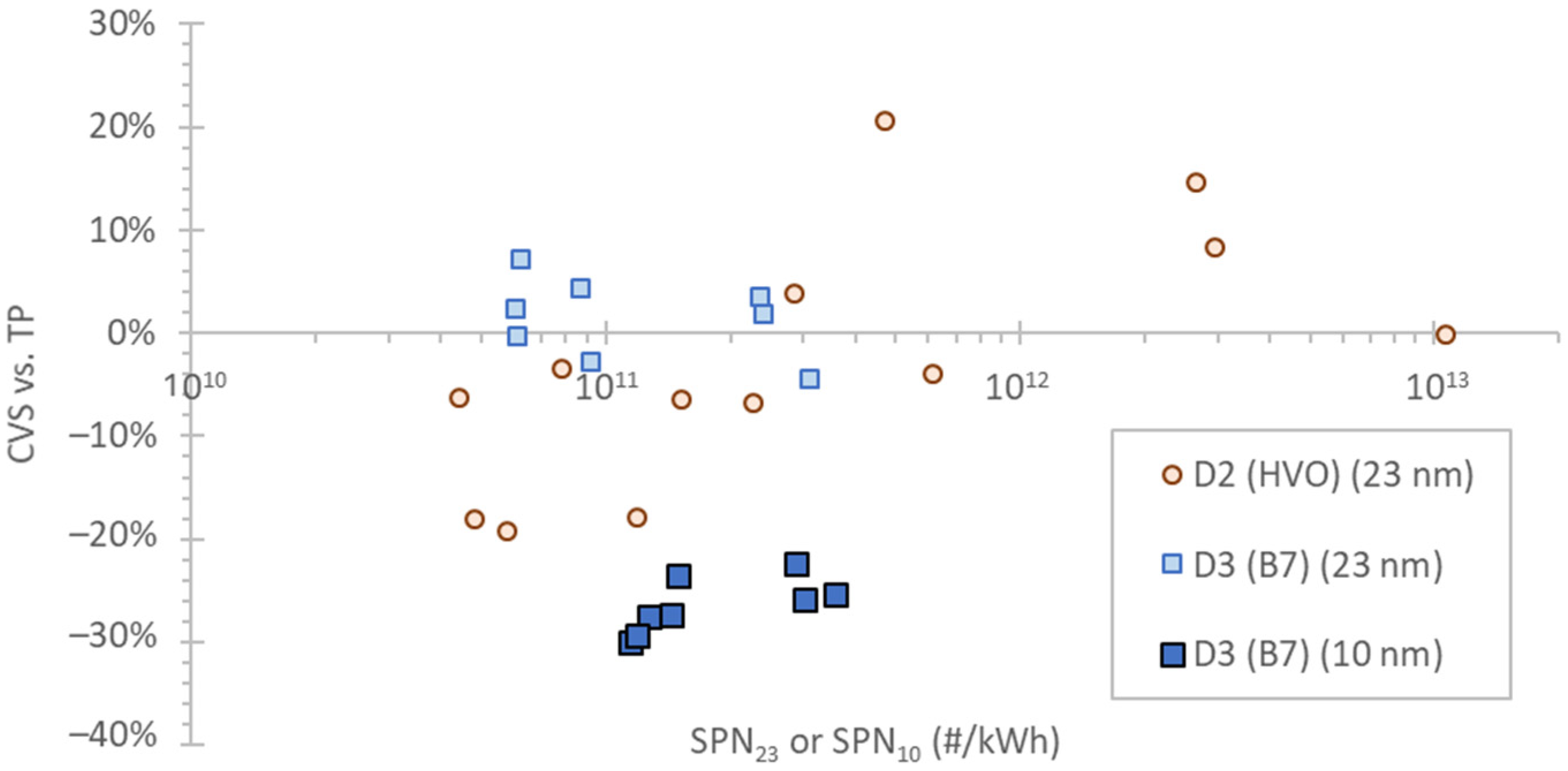
In heavy-duty engine regulation, the laboratory instruments are connected at the dilution tunnel with a constant volume sampler (CVS) or proportional partial flow systems. Recently, a technical resolution added the possibility to sample directly from the tailpipe as an equivalent option [53]. For two vehicles, there were simultaneous measurements at the tailpipe and the CVS (Figure 2).
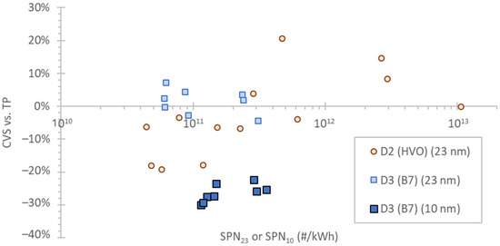
Figure 2.
Difference in reference instruments at the tailpipe (TP) and dilution tunnel (CVS). The instruments were the APCs from AVL. B7 refers to diesel fuel with 7% biofuel, and HVO refers to hydrotreated vegetable oil. SPN = solid particle number.
The results showed excellent agreement for the 23 nm laboratory instruments but a 20–30% difference for the 10 nm instruments. The underestimation at the CVS could be due to the higher diffusion losses of the small particles in the connection tube. At the chassis dynamometer of our study, the connection tube between the vehicle and the dilution tunnel was long (8 m, the last 4 m insulated) and could further increase the differences between the two sampling locations (tailpipe and CVS). Furthermore, heavy-duty engines’ exhaust gas temperature is high, and the cooling in the long tube could have resulted in high thermophoretic losses. The differences are in the expected range between systems sampling raw and diluted exhaust gas for heavy-duty engines [22,63] or light-duty vehicles [64] exhaust.
3.2. Vehicle SPN Emissions
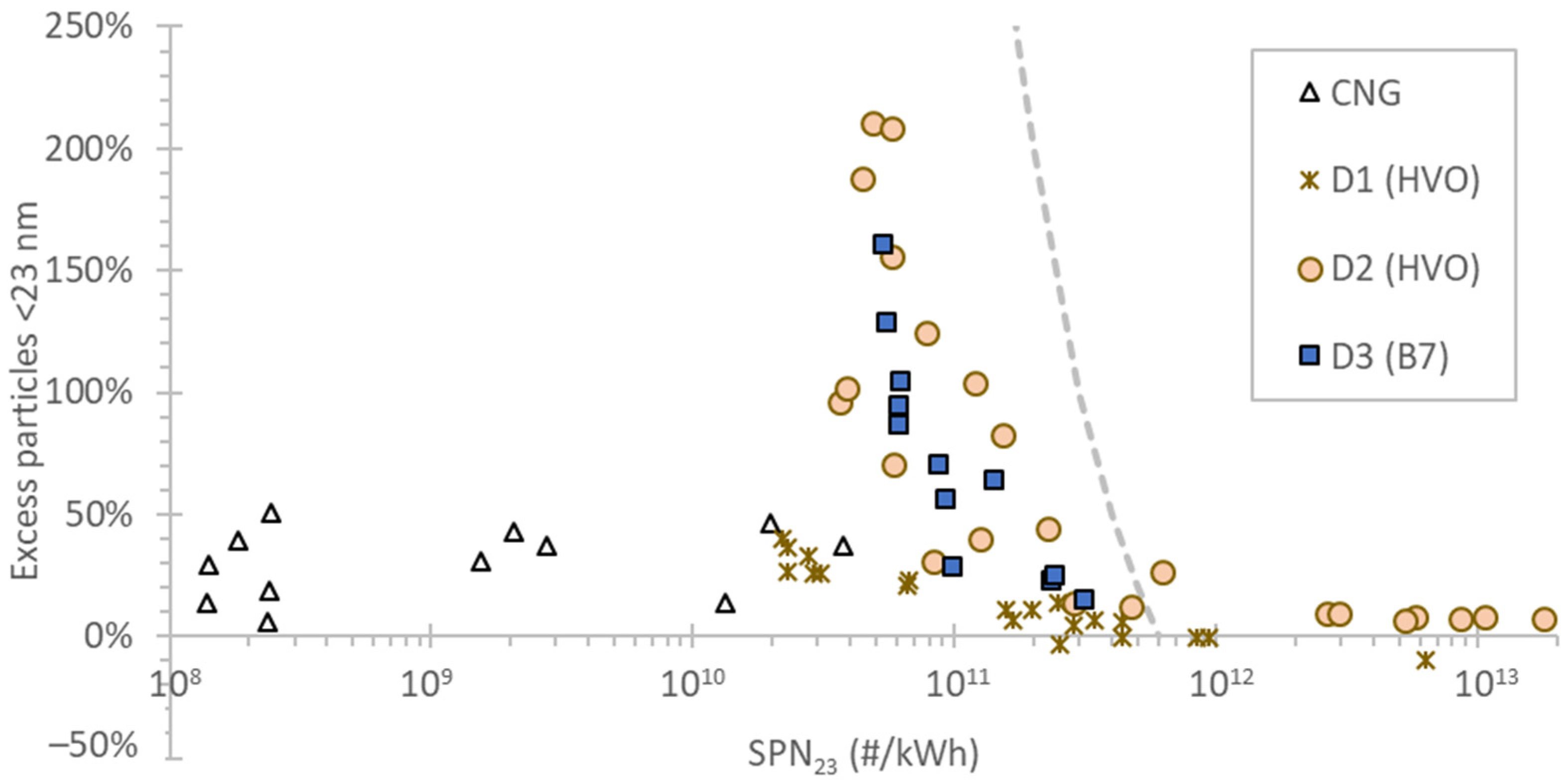
The SPN emissions ranged from 108 #/kWh up to 2 × 10¹³ #/kWh. Note that the high emissions are from the cold start parts (first 900 s) of the cycles. As mentioned in the experimental part, the tests are from different projects, some of them challenging the diesel particulate filters (DPFs) and some at low ambient temperatures. Furthermore, the analysis did not follow the regulation, but only parts of the cycles were considered here to compare the instruments on a wide range of emission levels. The lowest emissions, practically in the background of the instruments and setup, were from the CNG vehicle equipped with a particulate filter. The majority of the emissions were around 1011 #/kWh. Although the absolute emission levels of the vehicles are of no interest to this study, the relative difference between 23 nm and 10 nm concentrations can help understand possible deviations from the instruments. Figure 3 plots the excess particles below 23 nm, that is, {(SPN10 − SPN23)/SPN23}, as a function of the SPN23 emission levels.
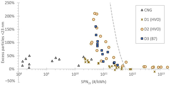
Figure 3.
Particle concentration below 23 nm in function of emission levels for various vehicles. The dotted line is the 6 × 10¹¹ #/kWh limit for >10 nm particles. SPN = solid particle number.
For vehicles CNG and D1, the percentage is <50%, a number typical for light-duty vehicles [17] and some heavy-duty diesel engines [17,65,66]. CNG engines have a typically high percentage of sub-23 nm particles [17,19], but in our study, a particulate filter was installed, and thus the sub-23 nm particles were also captured efficiently [18,67,68,69]. For D2 and D3, the percentages are very high (>50%) in the range of 7 × 10¹⁰ #/kWh to 3 × 10¹¹ #/kWh. Such high levels have also been reported by other studies [21,22]. This range is at or above the Commission’s proposed “hot” limit for Euro 7 (2 × 10¹¹ #/kWh for SPN10), but within the Council’s proposal of 9 × 10¹¹ #/kWh [70]. However, for the current SPN23 limit of 6 × 10¹¹ #/kWh, this high percentage is not so relevant because it is equivalent to 10–25% of the SPN23 limit, and most importantly, most of these particles are below 23 nm. At high concentrations, typically during cold starts or regenerations, the percentages are very low, indicating that the nature of the particles is different. Based on the literature, the particles during cold start at high concentrations have fuel combustion origins (i.e., soot), while those in the 1011 #/kWh range during hot vehicle operation are formed by urea origins [23]. At the high-speed part of the cycle, high soot emissions due to passive regeneration can also be measured [17,71,72,73].
3.3. Real-Time Graph Examples
For a better understanding of the final results, some examples are given in this section.
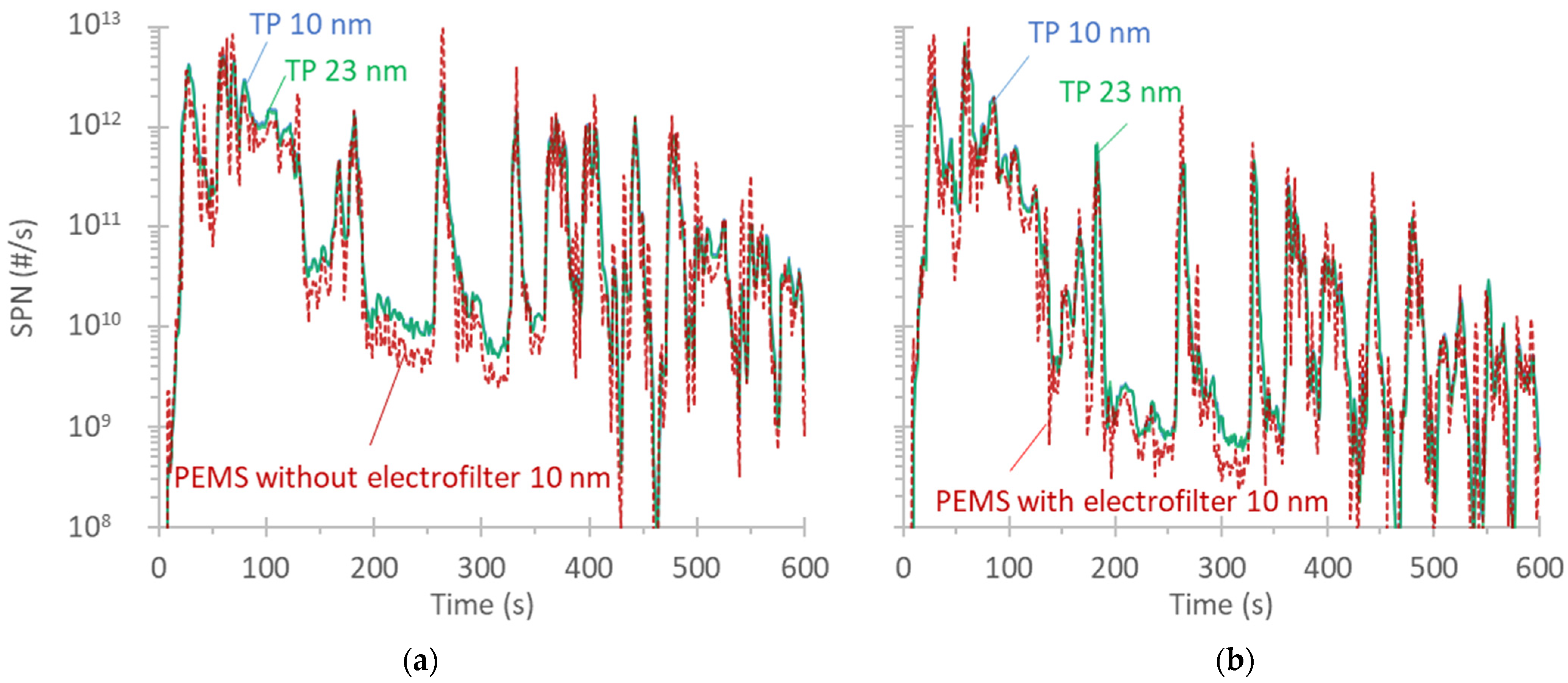
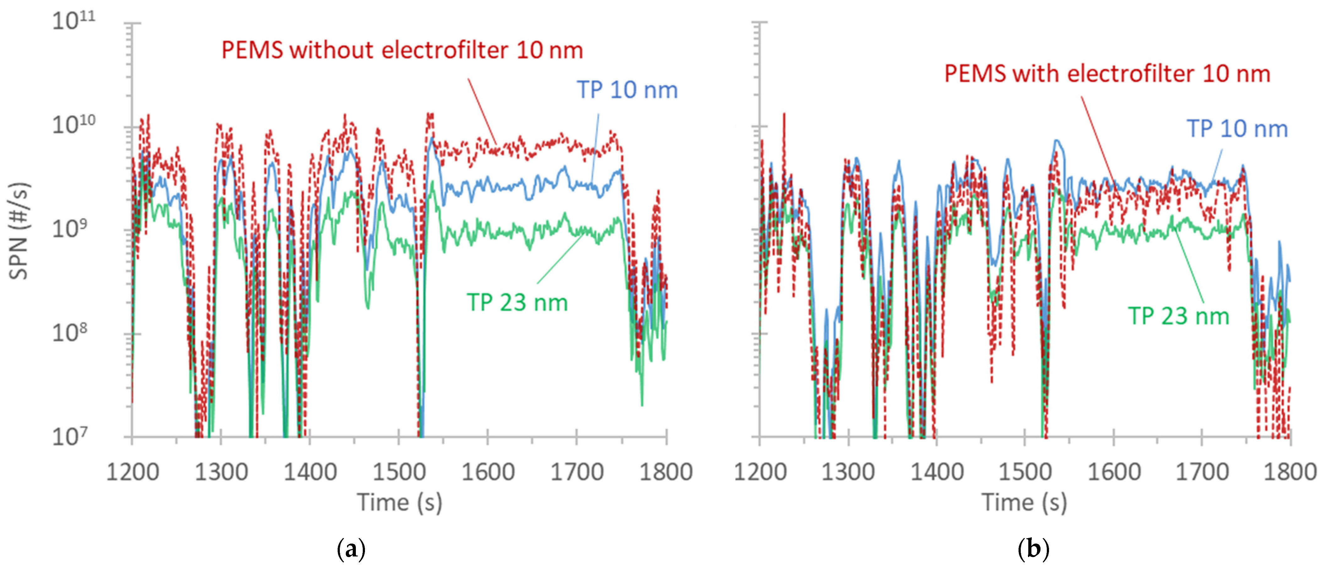
Figure 4 plots real-time emissions during the cold start part of a WHVC at −7 °C for vehicle D2. Two tests on two different days are plotted. In the first one (Figure 4a), the AVL MOVE PEMS was without the electrofilter activated, while in the second, it was with the electrofilter activated (Figure 4b). The small difference at the absolute levels of the two tests has to do probably with the DPF fill state. The two reference instruments at the tailpipe were almost indistinguishable, indicating that the mean size of the particles was >23 nm and thus soot in nature. The PEMS was measuring slightly lower: on average, 4% and 1% for the two tests. Thus, the electrofilter had no obvious impact on the absolute levels during the cold start, where relatively large particles are expected.
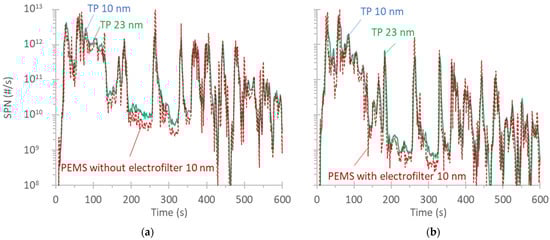
Figure 4.
Real-time solid particle number (SPN) emissions during a cold start of WHVC at an ambient temperature of −7 °C: (a) PEMS without the electrofilter activated and (b) PEMS with the electrofilter activated. The PEMS was the MOVE from AVL. PEMS = portable emissions measurement system; TP = tailpipe; WHVC = worldwide harmonized heavy-duty vehicles cycle.
Figure 5 plots the real-time emissions during the hot motorway part of a WHVC at −7 °C. As previously, two tests from the same vehicle on two different days are plotted. In the first one, the AVL MOVE PEMS was without the electrofilter activated (Figure 5a), while in the second, it was with the electrofilter activated (Figure 5b). The absolute levels of the two tests were quite similar. The two reference instruments at the tailpipe had a big difference, indicating that the mean size of the particles was <23 nm, most likely from urea. The PEMS was measuring much higher (+110% at an emission level of 1 × 10¹¹ #/kWh) than the 10 nm reference instrument at the first test, but almost identical at the second with the electrofilter activated. This indicates that the particles were indeed highly charged urea particles [62], captured efficiently by the electrofilter [46].
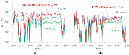
Figure 5.
Real-time solid particle number (SPN) emissions during the hot motorway part of a WHVC at an ambient temperature of −7 °C: (a) PEMS without the electrofilter activated and (b) PEMS with the electrofilter activated. The PEMS was the MOVE from AVL. PEMS = portable emissions measurement system; TP = tailpipe; WHVC = worldwide harmonized heavy-duty vehicles cycle.
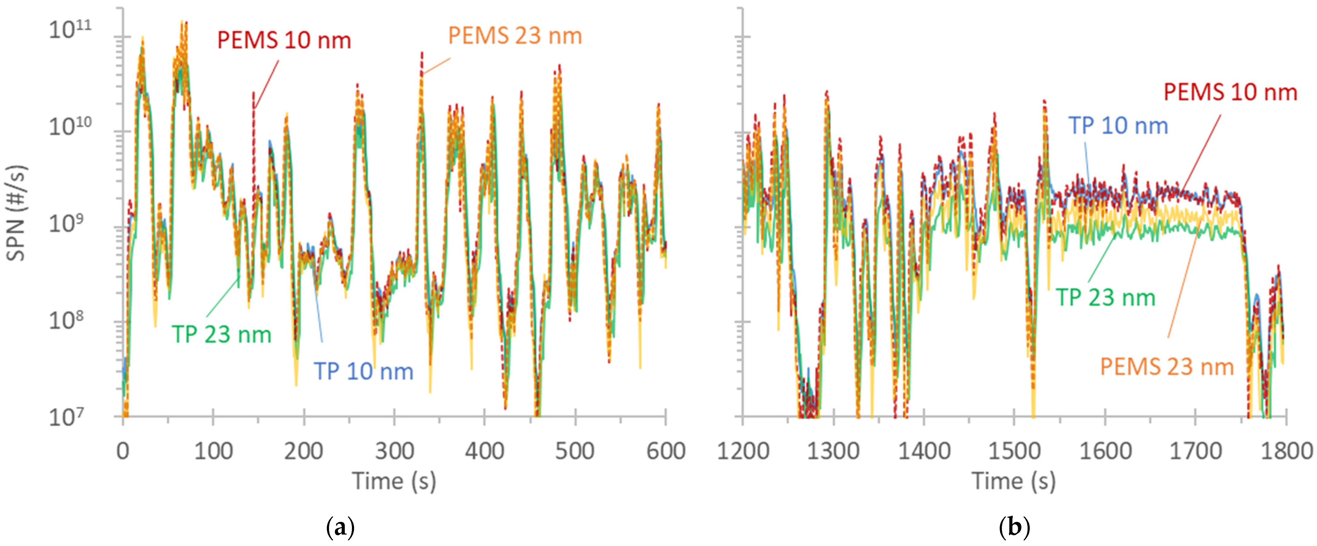
Figure 6 plots the real-time emissions of a WHVC at 23 °C, where 23 nm and 10 nm PEMS OBS from Horiba are compared with reference instruments at the tailpipe. At cold start (Figure 6a), the reference instruments were close to each other, and thus the mean particle size was >23 nm. Both PEMS had higher spikes than the reference instruments, which indicates either faster response time or a small pressure dependency. Pressure fluctuations may be caused by the dynamic pressure generated by exhaust flow in addition to the back (static) pressure caused by the connection to the CVS. For the specific cold start phase (900 s), the overestimation of PEMS was 53% (10 nm) and 66% (23 nm). The (under)pressure recorded inside the optical device of the PEMS fluctuated between 91 and 103 kPa in the tests in Figure 6 and other cycles with vehicle D3, while in the tests with vehicle D1, it fluctuated between 90 and 95 kPa. It is not clear what might have resulted in higher backpressure in the specific setup. The main difference between the two vehicles was that there were many instruments sampling close to each other. However, it is unlikely that the low sampling flow rates of the instruments might have affected each other. For this diesel vehicle, the 45° probe was placed facing the flow, so the instrument was more sensitive to such pressure fluctuations. With the CNG vehicle, the probe was placed the other way around to be protected by big droplets of condensate. The real-time signals with vehicle D1 are not plotted because the reference instruments were at the CVS; any difference might be partly misleading due to diffusion and smoothening taking place in the connection tube to the dilution tunnel.

Figure 6.
Real-time solid particle number (SPN) emissions during a worldwide harmonized heavy-duty vehicles cycle (WHVC) at an ambient temperature of 23 °C: (a) cold start and (b) last motorway part. The PEMS was the OBS from Horiba. PEMS = portable emissions measurement system; TP = tailpipe reference system.
Figure 6b plots the motorway part of the cycle. The differences at accelerations were still evident, while at steady conditions, the absolute levels of the 10 nm instruments were in agreement. The 23 nm PEMS was measuring higher than the 23 nm laboratory reference. For the motorway part of this cycle, the difference was 7% for the 10 nm PEMS and 46% for the 23 nm PEMS. This difference indicates a small difference in the cut-off size of the CPCs inside the PEMS and the reference instrument [58]. Differences in the 23 nm CPCs’ calibrations are not uncommon and have been reported by other researchers as well [74]. However, for 10 nm instruments, the calibration material is not so important, and the differences become smaller [55].
Figure 7 plots the first 1200 s of a RWC with the CNG vehicle. Figure 7a plots the 23 nm Horiba OBS and the 23 nm reference at the tailpipe. Figure 7b plots the AVL MOVE 10 nm and the 10 nm reference at the tailpipe. The relative humidity, as measured inside the PEMS instruments with their internal sensors, is also given.
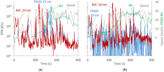
Figure 7.
Real-time solid particle number (SPN) emissions during a real-world cycle (RWC) at an ambient temperature of −7 °C with the compressed natural gas (CNG) vehicle: (a) Horiba OBS 23 nm and (b) AVL MOVE 10 nm. PEMS = portable emissions measurement system; RH = relative humidity.
The emissions, due to the particulate filter of the CNG vehicle, were very low, as expected [75], close to the background (detection levels) of the instruments. For PEMS, the maximum zero level allowed in the regulation is 5000 #/cm3. There was a spike at the beginning of the test with the ignition on and the first idling seconds. Another spike was at around 300 s, where the speed increased to 30 km/h, along with an increase in the relative humidity levels (>30%) inside the instruments. At the beginning of the cycle, the water content of the exhaust gas was condensing due to the low ambient temperature. As the temperature increased, condensation stopped. It is not clear whether this spike at around 300 s was due to true particle emissions, as not all instruments measured it, and in some cases, there was a difference in timing. Based on the real-time signals, we cannot conclude that there was a dependency of the instrument’s signals on the humidity. However, condensates inside the instruments can create spikes [76]. Water condensates can trap many particles, which are released when the droplet evaporates in the heated section of the instrument. For the specific test, the cold start emissions were 2 × 10¹⁰ #/kWh according to PEMS 23 nm and double according to the reference instruments.
3.4. PEMS vs. Laboratory Instruments
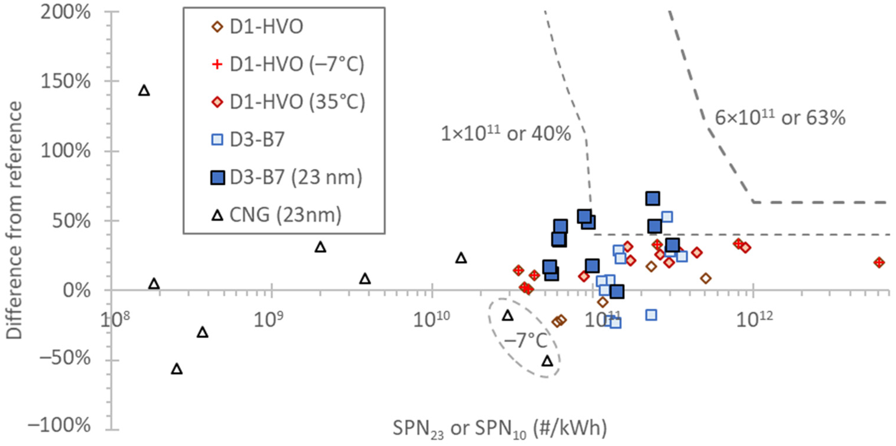
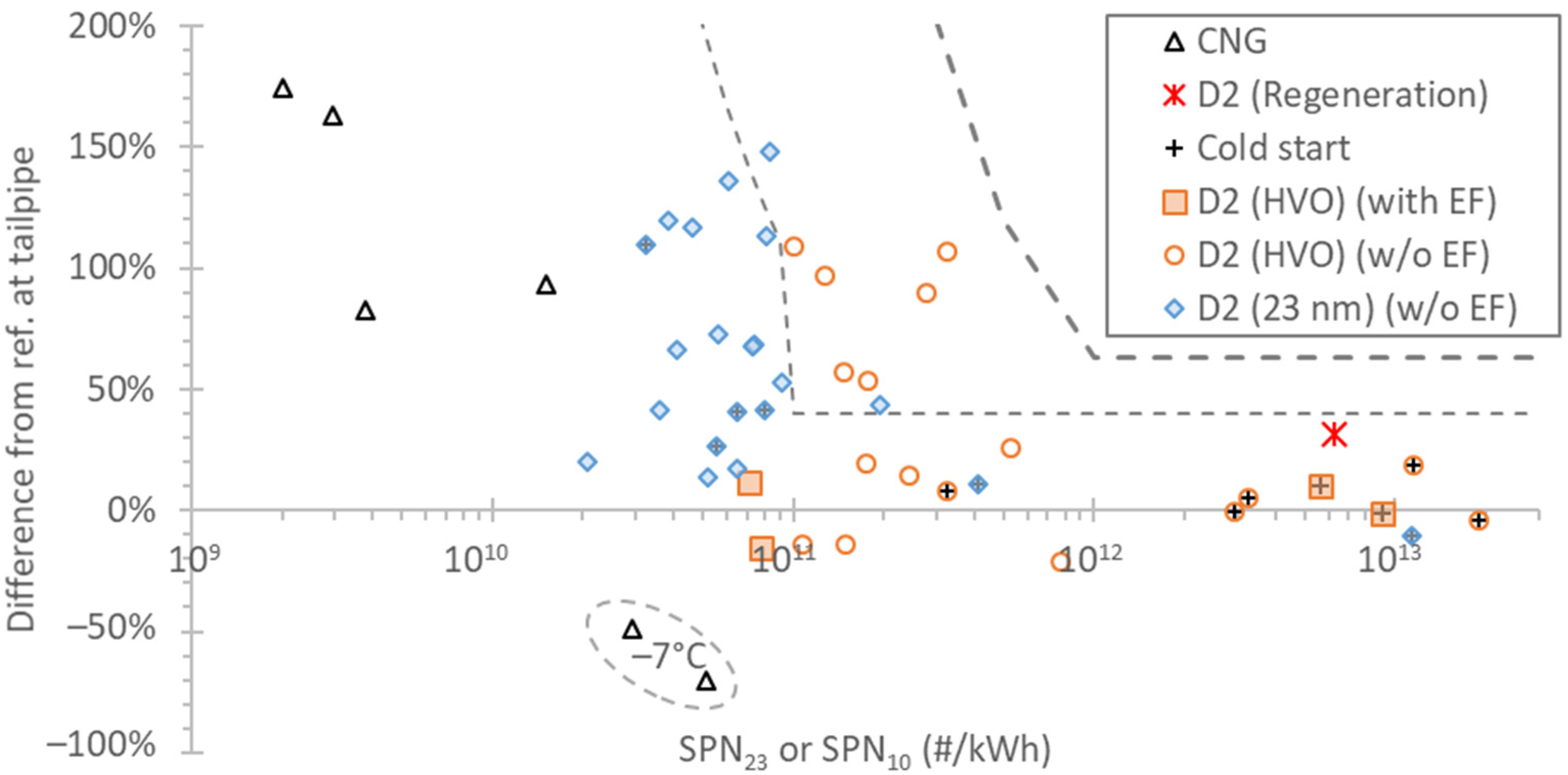
The following figures summarize the differences between the PEMS and the laboratory reference instruments. To put the results into perspective, two curves are also given: 6 × 10¹¹ #/kWh or 63% (whichever is larger) and 1 × 10¹¹ #/kWh or 40% (whichever is larger). The first curve corresponds to the Euro VI limit and on-road margin that takes into account the PEMS measurement uncertainties. The second curve is a reasonable uncertainty for the Euro 7 proposed “hot” limit of 2 × 10¹¹ #/kWh. Furthermore, an uncertainty of 40% was taken into account for the proposed limits in the Euro 7 assessment of SPN limits for heavy-duty vehicles [10]. These values are also close to the PEMS uncertainty based on theoretical estimations [30].
Figure 8 plots the deviations of Horiba’s 23 nm and 10 nm OBS from the reference instruments. The differences were well within the “tighter” curve, but with a few exceptions for both the 10 nm and 23 nm PEMS. These had to do with pressure sensitivity, as discussed in Figure 6. The differences were not related to any ambient temperature effect. For the D1 vehicle, the differences between the PEMS and reference instrument were at the same levels, irrespective of the ambient temperature. The same applied to the CNG vehicle. The CNG points with negative differences could be cases where the reference instrument was overestimating due to condensate spikes, as discussed in Figure 7.
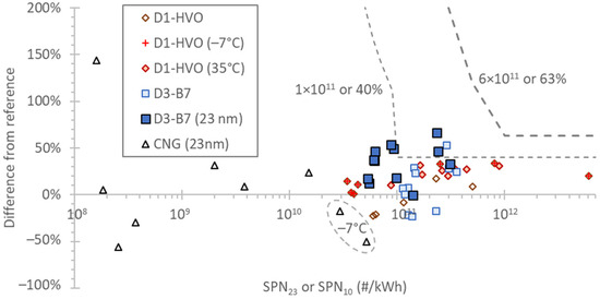
Figure 8.
Difference of Horiba’s OBS PEMS from laboratory reference instruments. Results for 10 nm instruments, unless otherwise specified. CNG = compressed natural gas; HVO = hydrotreated vegetable oil; SPN = solid particle number.
Figure 9 plots the deviations of AVL’s 23 nm and 10 nm MOVE from the reference instruments. The differences were also within the “tighter” curve, with the exception of the hot tests of D2 when the electrofilter was not active. As discussed in Figure 5, this had to do with the charged urea-originating particles that resulted in an overestimation of the instrument’s signal. For the 23 nm PEMS, which had no electrofilter, the impact of charged urea particles was still negligible, as the majority of these particles are typically smaller than 23 nm. The >23 nm levels were <1011 #/kWh, which is <17% of the 6 × 10¹¹ #/kWh laboratory limit. Nevertheless, the heavy-duty 23 nm PEMS has an electrofilter or pre-charger installed. The difference during active regeneration (around 30%, see Appendix A) was also <40%, even without the electrofilter activated, because these particles are mainly soot penetrating the DPF. Due to the low filter efficiency [77], many particles go through the DPF [17], and the concentration of any urea particles formed downstream of the DPF is relatively low. The ambient temperature had no effect on the PEMS. With the CNG vehicle, the negative differences could be condensate spikes of the reference instrument (see Figure 7), while the >100% differences at the 109 #/kWh range are due to the low concentrations, close to the background levels of the specific PEMS.

Figure 9.
Difference of AVL’s MOVE PEMS from laboratory reference instruments. Results for 10 nm instruments, unless otherwise specified. All tests with the D2 vehicle and EF were done at −7 °C. CNG = compressed natural gas; EF = electrofilter; HVO = hydrotreated vegetable oil; SPN = solid particle number.
4. Conclusions
In this study, PEMS were compared with laboratory-grade instruments measuring the exhaust gas of four N3 Euro VI step E vehicles (three diesel and one CNG), all equipped with particulate filters. The tests covered different test cycles, different ambient temperatures, cold and hot starts, and different fuels. The differences between PEMS and the reference instruments were typically below 40% or 1011 #/kWh at a wide range of conditions and emission levels. The PEMS operated normally from −7 °C up to 35 °C. Two issues were identified, though, that resulted in differences of 50–100% at the 1011 #/kWh range: the AVL MOVE had a sensitivity to pre-charged particles originating from urea. This was solved by activating the electrofilter. The Horiba OBS had pressure fluctuation issues with one vehicle. The reasons are not clear, but we assume a different orientation of the probe would minimize these effects. We recommend always using the sampling probe without facing the flow in order to protect the instruments from big flakes or exhaust condensates and minimize pressure pulsation impact. Furthermore, the pressure fluctuations were measured by the device and could trigger a warning in the future. Although this study demonstrated the robustness of PEMS under a wide range of conditions, more tests in the two cases identified are recommended to confirm that in the future, such cases will not take place.
Author Contributions
Conceptualization, B.G.; formal analysis, B.G.; writing—original draft preparation, B.G.; writing—review and editing, A.M., S.B., R.G. and R.S.-B. All authors have read and agreed to the published version of the manuscript.
Funding
This research received no external funding.
Institutional Review Board Statement
Not applicable.
Informed Consent Statement
Not applicable.
Data Availability Statement
The raw data supporting the conclusions of this article will be made available by the authors on request.
Acknowledgments
The authors would like to acknowledge the technical staff (M. Cadario, D. Zanardini, R. Quarto, and P. Macri) and AVL’s resident engineer, A. Bonamin, for the execution of the tests. The authors also would like to acknowledge Horiba (Y. Otsuki) and AVL (C. Dardiotis and R. Davok) for providing the 10 nm PEMS instruments used in this study.
Conflicts of Interest
The authors declare no conflicts of interest.
Disclaimer
The information and views set forth are those of the author(s) and do not necessarily reflect the official opinion of the European Commission. Neither the European Union institutions and bodies nor any person acting on their behalf may be held responsible for the use that may be made of the information contained therein. Mention of trade or commercial products does not constitute endorsement or recommendation by the authors or the European Commission.
Abbreviations
| APC | advanced particle counter |
| CNG | compressed natural gas |
| CPC | condensation particle counter |
| CS | catalytic stripper |
| CVS | constant volume sampler (dilution tunnel); |
| D | diesel vehicle |
| DC | diffusion charger |
| DPF | diesel particulate filter |
| EF | electrofilter |
| ET | evaporation tube |
| EU | European Union |
| FAME | fatty acid methyl ester |
| HVO | hydrotreated vegetable oil |
| JRC | Joint Research Centre |
| PEMS | portable emission measurement systems |
| PF | particulate filter |
| RWC | real-world cycle |
| SCR | selective catalytic reduction (for NOx) |
| SPN | solid particle number |
| TP | tailpipe |
| VTP | verification testing procedure |
| WHVC | worldwide harmonized heavy-duty vehicles cycle |
Appendix A
Figure A1 plots the second half of a WHVC where an active regeneration took place. The emission levels were much higher compared to other cycles where no active regeneration took place. The 23 nm from the CVS and 10 nm from the TP patterns with the reference instruments are close to each other. The 10 nm PEMS has some differences: there are some higher spikes during accelerations, while at the steady speed part of the cycle (1550 s and later), it was lower. On average, the difference between the PEMS and the TP reference instrument was 30% higher. This difference is close to the difference at the first part of the cycle (25%), indicating that the regeneration did not have a big effect on the behavior of the PEMS.
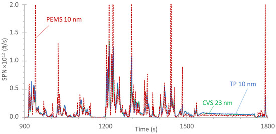
Figure A1.
Real-time solid particle number (SPN) emissions during a regeneration at the last half of a worldwide harmonized heavy-duty vehicles cycle (WHVC) at an ambient temperature of 23 °C. The PEMS was the MOVE from AVL.
Figure A1.
Real-time solid particle number (SPN) emissions during a regeneration at the last half of a worldwide harmonized heavy-duty vehicles cycle (WHVC) at an ambient temperature of 23 °C. The PEMS was the MOVE from AVL.
References
- Domagała, J.; Kadłubek, M. Economic, Energy and Environmental Efficiency of Road Freight Transportation Sector in the EU. Energies 2022, 16, 461. [Google Scholar] [CrossRef]
- Balazadeh Meresht, N.; Moghadasi, S.; Munshi, S.; Shahbakhti, M.; McTaggart-Cowan, G. Advances in Vehicle and Powertrain Efficiency of Long-Haul Commercial Vehicles: A Review. Energies 2023, 16, 6809. [Google Scholar] [CrossRef]
- Bebkiewicz, K.; Chłopek, Z.; Lasocki, J.; Szczepański, K.; Zimakowska-Laskowska, M. The Inventory of Pollutants Hazardous to the Health of Living Organisms, Emitted by Road Transport in Poland between 1990 and 2017. Sustainability 2020, 12, 5387. [Google Scholar] [CrossRef]
- de Meij, A.; Astorga, C.; Thunis, P.; Crippa, M.; Guizzardi, D.; Pisoni, E.; Valverde, V.; Suarez-Bertoa, R.; Oreggioni, G.D.; Mahiques, O.; et al. Modelling the Impact of the Introduction of the EURO 6d-TEMP/6d Regulation for Light-Duty Vehicles on EU Air Quality. Appl. Sci. 2022, 12, 4257. [Google Scholar] [CrossRef]
- Wallington, T.J.; Anderson, J.E.; Dolan, R.H.; Winkler, S.L. Vehicle Emissions and Urban Air Quality: 60 Years of Progress. Atmosphere 2022, 13, 650. [Google Scholar] [CrossRef]
- Keramydas, C.; Ntziachristos, L.; Tziourtzioumis, C.; Papadopoulos, G.; Lo, T.-S.; Ng, K.-L.; Wong, H.-L.A.; Wong, C.K.-L. Characterization of Real-World Pollutant Emissions and Fuel Consumption of Heavy-Duty Diesel Trucks with Latest Emissions Control. Atmosphere 2019, 10, 535. [Google Scholar] [CrossRef]
- Liu, Y.; Tan, J. Green Traffic-Oriented Heavy-Duty Vehicle Emission Characteristics of China VI Based on Portable Emission Measurement Systems. IEEE Access 2020, 8, 106639–106647. [Google Scholar] [CrossRef]
- Giechaskiel, B.; Melas, A.; Martini, G.; Dilara, P. Overview of Vehicle Exhaust Particle Number Regulations. Processes 2021, 9, 2216. [Google Scholar] [CrossRef]
- Su, S.; Hou, P.; Wang, X.; Lyu, L.; Ge, Y.; Lyu, T.; Lai, Y.; Luo, W.; Wang, Y. Evaluating the Measurement Uncertainty of On-Road NOx Using a Portable Emission Measurement System (PEMS) Based on Real Testing Data in China. Atmosphere 2023, 14, 702. [Google Scholar] [CrossRef]
- European Commission Euro 7 Proposal. 2022. Available online: https://single-market-economy.ec.europa.eu/sectors/automotive-industry/environmental-protection/emissions-automotive-sector_en (accessed on 6 January 2024).
- General Secretariat of the Council Agreed Document ST_5142_2024_INIT: Regulation on Type-Approval of Motor Vehicles and Engines and of Systems, Components and Separate Technical Units Intended for Such Vehicles, with Respect to Their Emissions and Battery Durability (Euro 7)—Letter to the Chair of the European Parliament ENVI Committee. 2024. Available online: https://eur-lex.europa.eu/legal-content/EN/TXT/?uri=consil%3AST_5142_2024_INIT (accessed on 6 January 2024).
- Wang, T.; Quiros, D.C.; Thiruvengadam, A.; Pradhan, S.; Hu, S.; Huai, T.; Lee, E.S.; Zhu, Y. Total Particle Number Emissions from Modern Diesel, Natural Gas, and Hybrid Heavy-Duty Vehicles during on-Road Operation. Environ. Sci. Technol. 2017, 51, 6990–6998. [Google Scholar] [CrossRef]
- Napolitano, P.; Alfè, M.; Guido, C.; Gargiulo, V.; Fraioli, V.; Beatrice, C. Particle Emissions from a HD SI Gas Engine Fueled with LPG and CNG. Fuel 2020, 269, 117439. [Google Scholar] [CrossRef]
- Kontses, A.; Triantafyllopoulos, G.; Ntziachristos, L.; Samaras, Z. Particle Number (PN) Emissions from Gasoline, Diesel, LPG, CNG and Hybrid-Electric Light-Duty Vehicles under Real-World Driving Conditions. Atmos. Environ. 2020, 222, 117126. [Google Scholar] [CrossRef]
- Distaso, E.; Amirante, R.; Calò, G.; De Palma, P.; Tamburrano, P. Evolution of Soot Particle Number, Mass and Size Distribution along the Exhaust Line of a Heavy-Duty Engine Fueled with Compressed Natural Gas. Energies 2020, 13, 3993. [Google Scholar] [CrossRef]
- Khalek, I.A.; Badshah, H.; Premnath, V.; Brezny, R. Solid Particle Number and Ash Emissions from Heavy-Duty Natural Gas and Diesel w/SCRF Engines; Paper Number 2018-01-0362; SAE: Warrendale, PA, USA, 2018. [Google Scholar]
- Giechaskiel, B. Solid Particle Number Emission Factors of Euro VI Heavy-Duty Vehicles on the Road and in the Laboratory. Int. J. Environ. Res. Public Health 2018, 15, 304. [Google Scholar] [CrossRef] [PubMed]
- Toumasatos, Z.; Kontses, A.; Doulgeris, S.; Samaras, Z.; Ntziachristos, L. Particle Emissions Measurements on CNG Vehicles Focusing on Sub-23 nm. Aerosol Sci. Technol. 2021, 55, 182–193. [Google Scholar] [CrossRef]
- Wang, X.; Zhang, L.; Wang, M.; Jing, X.; Gu, X. Sub-23 nm Solid Particle Number Emission Characteristics for a Heavy-Duty Engine Fuelled with Compression Natural Gas. E3S Web Conf. 2021, 329, 01012. [Google Scholar] [CrossRef]
- Sala, R.; Bielaczyc, P.; Brzezanski, M. Concept of Vaporized Urea Dosing in Selective Catalytic Reduction. Catalysts 2017, 7, 307. [Google Scholar] [CrossRef]
- Shen, B.; Li, Z.; Kong, X.; Li, M.; Li, Z.; Shuai, S.; Liu, S. Experimental and Numerical Investigations into Effects of Urea-Water Solution Injection on Tailpipe Particulate Matter Emissions. Process Saf. Environ. Prot. 2021, 148, 927–938. [Google Scholar] [CrossRef]
- Giechaskiel, B.; Schwelberger, M.; Kronlund, L.; Delacroix, C.; Locke, L.A.; Khan, M.Y.; Jakobsson, T.; Otsuki, Y.; Gandi, S.; Keller, S.; et al. Towards Tailpipe Sub-23 nm Solid Particle Number Measurements for Heavy-Duty Vehicles Regulations. Transp. Eng. 2022, 9, 100137. [Google Scholar] [CrossRef]
- Giechaskiel, B.; Selleri, T.; Gioria, R.; Melas, A.D.; Franzetti, J.; Ferrarese, C.; Suarez-Bertoa, R. Assessment of a Euro VI Step E Heavy-Duty Vehicle’s Aftertreatment System. Catalysts 2022, 12, 1230. [Google Scholar] [CrossRef]
- Amanatidis, S.; Ntziachristos, L.; Giechaskiel, B.; Bergmann, A.; Samaras, Z. Impact of Selective Catalytic Reduction on Exhaust Particle Formation over Excess Ammonia Events. Environ. Sci. Technol. 2014, 48, 11527–11534. [Google Scholar] [CrossRef] [PubMed]
- Bao, J.; Mao, L.; Zhang, Y.; Fang, H.; Shi, Y.; Yang, L.; Yang, H. Effect of Selective Catalytic Reduction System on Fine Particle Emission Characteristics. Energy Fuels 2016, 30, 1325–1334. [Google Scholar] [CrossRef]
- Robinson, M.A.; Backhaus, J.; Foley, R.; Liu, Z.G. The Effect of Diesel Exhaust Fluid Dosing on Tailpipe Particle Number Emissions; Paper Number 2016-01-0995; SAE: Warrendale, PA, USA, 2016. [Google Scholar]
- Ryddner, D.T.; Trujillo, M.F. Modeling Urea-Water Solution Droplet Evaporation. Emiss. Control Sci. Technol. 2015, 1, 80–97. [Google Scholar] [CrossRef]
- Brack, W.; Heine, B.; Birkhold, F.; Kruse, M.; Deutschmann, O. Formation of Urea-Based Deposits in an Exhaust System: Numerical Predictions and Experimental Observations on a Hot Gas Test Bench. Emiss. Control Sci. Technol. 2016, 2, 115–123. [Google Scholar] [CrossRef]
- Wang, H.; Zhai, T.; Zhang, L.; Li, J.; Xue, Z.; Wang, J.; Ji, Z.; Li, W.; Wang, Y. The Effect of Various Urea-in-Water Solution Types on Exhaust Particle Number Emission. Environ. Sci. Pollut. Res. 2023, 30, 108825–108831. [Google Scholar] [CrossRef] [PubMed]
- Giechaskiel, B.; Lähde, T.; Melas, A.D.; Valverde, V.; Clairotte, M. Uncertainty of Laboratory and Portable Solid Particle Number Systems for Regulatory Measurements of Vehicle Emissions. Environ. Res. 2021, 197, 111068. [Google Scholar] [CrossRef]
- Li, G.; Luo, W.; Zhang, C.; Cui, B.; Chang, L.; Chen, L. Calibration and Experimental Study of a Self-Developed Particle-Number Measurement Instrument. Processes 2023, 12, 12. [Google Scholar] [CrossRef]
- Schriefl, M.A.; Bergmann, A.; Fierz, M. Design Principles for Sensing Particle Number Concentration and Mean Particle Size with Unipolar Diffusion Charging. IEEE Sens. J. 2019, 19, 1392–1399. [Google Scholar] [CrossRef]
- Qi, C.; Asbach, C.; Shin, W.G.; Fissan, H.; Pui, D.Y.H. The Effect of Particle Pre-Existing Charge on Unipolar Charging and Its Implication on Electrical Aerosol Measurements. Aerosol Sci. Technol. 2009, 43, 232–240. [Google Scholar] [CrossRef]
- Khan, M.Y.; Patel, M.; Scott, N.; Liew, C.M.; Peng, C.; Luo, W.; Rahman, M.; Gramlich, N.; Eames, J.; Phillips, J.A. Assessment of In-Use Solid Particle Number Measurement Systems against Laboratory Systems; Paper Number 2020-01-5074; SAE: Warrendale, PA, USA, 2020. [Google Scholar]
- Ma, C.; Wu, L.; Mao, H.; Fang, X.; Wei, N.; Zhang, J.; Yang, Z.; Zhang, Y.; Lv, Z.; Yang, L. Transient Characterization of Automotive Exhaust Emission from Different Vehicle Types Based on On-Road Measurements. Atmosphere 2020, 11, 64. [Google Scholar] [CrossRef]
- Barrios, C.C.; Álvarez-Mateos, P.; Urueña, A.; Díez, D.; García-Martín, J.F. Experimental Investigation on Emissions Characteristics from Urban Bus Fueled with Diesel, Biodiesel and an Oxygenated Additive from Residual Glycerin from Biodiesel Production. Processes 2021, 9, 987. [Google Scholar] [CrossRef]
- Ziółkowski, A.; Fuć, P.; Lijewski, P.; Jagielski, A.; Bednarek, M.; Kusiak, W. Analysis of Exhaust Emissions from Heavy-Duty Vehicles on Different Applications. Energies 2022, 15, 7886. [Google Scholar] [CrossRef]
- Chen, J.; Li, Y.; Meng, Z.; Feng, X.; Wang, J.; Zhou, H.; Li, J.; Shi, J.; Chen, Q.; Shi, H.; et al. Study on Emission Characteristics and Emission Reduction Effect for Construction Machinery under Actual Operating Conditions Using a Portable Emission Measurement System (PEMS). J. Environ. Res. Public Health 2022, 19, 9546. [Google Scholar] [CrossRef] [PubMed]
- Skobiej, K.; Pielecha, J. Analysis of the Exhaust Emissions of Hybrid Vehicles for the Current and Future RDE Driving Cycle. Energies 2022, 15, 8691. [Google Scholar] [CrossRef]
- Zhang, Y.; Zhou, R.; Peng, S.; Mao, H.; Yang, Z.; Andre, M.; Zhang, X. Development of Vehicle Emission Model Based on Real-Road Test and Driving Conditions in Tianjin, China. Atmosphere 2022, 13, 595. [Google Scholar] [CrossRef]
- Cassiers, S.; Boveroux, F.; Martin, C.; Maes, R.; Martens, K.; Bergmans, B.; Idczak, F.; Jeanmart, H.; Contino, F. Emission Measurement of Buses Fueled with Biodiesel Blends during On-Road Testing. Energies 2020, 13, 5267. [Google Scholar] [CrossRef]
- Zhai, Z.; Tu, R.; Xu, J.; Wang, A.; Hatzopoulou, M. Capturing the Variability in Instantaneous Vehicle Emissions Based on Field Test Data. Atmosphere 2020, 11, 765. [Google Scholar] [CrossRef]
- Giechaskiel, B.; Lähde, T.; Gandi, S.; Keller, S.; Kreutziger, P.; Mamakos, A. Assessment of 10-nm Particle Number (PN) Portable Emissions Measurement Systems (PEMS) for Future Regulations. J. Environ. Res. Public Health 2020, 17, 3878. [Google Scholar] [CrossRef]
- Giechaskiel, B.; Schwelberger, M.; Delacroix, C.; Marchetti, M.; Feijen, M.; Prieger, K.; Andersson, S.; Karlsson, H.L. Experimental Assessment of Solid Particle Number Portable Emissions Measurement Systems (PEMS) for Heavy-Duty Vehicles Applications. J. Aerosol Sci. 2018, 123, 161–170. [Google Scholar] [CrossRef]
- Giechaskiel, B.; Bonnel, P.; Perujo, A.; Dilara, P. Solid Particle Number (SPN) Portable Emissions Measurement Systems (PEMS) in the European Legislation: A Review. J. Environ. Res. Public Health 2019, 16, 4819. [Google Scholar] [CrossRef]
- Schwelberger, M.; Mamakos, A.; Fierz, M.; Giechaskiel, B. Experimental Assessment of an Electrofilter and a Tandem Positive-Negative Corona Charger for the Measurement of Charged Nanoparticles Formed in Selective Catalytic Reduction Systems. Appl. Sci. 2019, 9, 1051. [Google Scholar] [CrossRef]
- Rimkus, A.; Žaglinskis, J.; Stravinskas, S.; Rapalis, P.; Matijošius, J.; Bereczky, Á. Research on the Combustion, Energy and Emission Parameters of Various Concentration Blends of Hydrotreated Vegetable Oil Biofuel and Diesel Fuel in a Compression-Ignition Engine. Energies 2019, 12, 2978. [Google Scholar] [CrossRef]
- Ortega, A.; Gkoumas, K.; Tsakalidis, A.; Pekár, F. Low-Emission Alternative Energy for Transport in the EU: State of Play of Research and Innovation. Energies 2021, 14, 7764. [Google Scholar] [CrossRef]
- d’Ambrosio, S.; Mancarella, A.; Manelli, A. Utilization of Hydrotreated Vegetable Oil (HVO) in a Euro 6 Dual-Loop EGR Diesel Engine: Behavior as a Drop-In Fuel and Potentialities along Calibration Parameter Sweeps. Energies 2022, 15, 7202. [Google Scholar] [CrossRef]
- Smigins, R.; Sondors, K.; Pirs, V.; Dukulis, I.; Birzietis, G. Studies of Engine Performance and Emissions at Full-Load Mode Using HVO, Diesel Fuel, and HVO5. Energies 2023, 16, 4785. [Google Scholar] [CrossRef]
- Pielecha, I.; Szwajca, F. Two- and Three-Stage Natural Gas Combustion System—Experimental Comparative Analysis. Energies 2023, 16, 3837. [Google Scholar] [CrossRef]
- Li, P.; Lü, L. Evaluating the Real-World NOx Emission from a China VI Heavy-Duty Diesel Vehicle. Appl. Sci. 2021, 11, 1335. [Google Scholar] [CrossRef]
- PMP GRPE 85-04: Proposed Amendments to ECE/TRANS/WP.29/GRPE/2021/17. 2022. Available online: https://unece.org/transport/events/wp29grpe-working-party-pollution-and-energy-85th-session (accessed on 6 January 2024).
- Swanson, J.; Kittelson, D. Evaluation of Thermal Denuder and Catalytic Stripper Methods for Solid Particle Measurements. J. Aerosol Sci. 2010, 41, 1113–1122. [Google Scholar] [CrossRef]
- Giechaskiel, B.; Melas, A. Impact of Material on Response and Calibration of Particle Number Systems. Atmosphere 2022, 13, 1770. [Google Scholar] [CrossRef]
- Biró, N.; Szőllősi, D.; Kiss, P. Particle Counter Design Upgrade for Euro 7. Atmosphere 2023, 14, 1411. [Google Scholar] [CrossRef]
- Nakamura, K.; Sugaya, Y.; Yamaguchi, K.; Kusaka, J.; Arndt, M.; Dardiotis, C. Characterization of Soot Loading and Filtration Efficiency of a Gasoline Particulate Filter with Photoacoustic Sensor and Particle Number Counting Systems. Atmosphere 2023, 14, 476. [Google Scholar] [CrossRef]
- Otsuki, Y.; Nakamura, H.; Kojima, K.; Kondo, K.; Haruta, K. Investigation in Calibration Procedures for Portable and Stationary Solid Particle Number Measurement Systems; Paper Number 2019-01-1187; SAE: Warrendale, PA, USA, 2019. [Google Scholar]
- Otsuki, Y.; Fukushima, S.; Nakamura, H.; Kojima, K.; Sakurai, H. Investigation of Equivalency between Laboratory-Grade and Portable Emissions Measurement Systems in Solid Particle Number Measurement Larger than 10 nm; Paper Number 2023-01-0391; SAE: Warrendale, PA, USA, 2023. [Google Scholar]
- Fierz, M.; Meier, D.; Steigmeier, P.; Burtscher, H. Aerosol Measurement by Induced Currents. Aerosol Sci. Technol. 2014, 48, 350–357. [Google Scholar] [CrossRef]
- Schriefl, M.A.; Nishida, R.T.; Knoll, M.; Boies, A.M.; Bergmann, A. Characterization of Particle Number Counters Based on Pulsed-Mode Diffusion Charging. Aerosol Sci. Technol. 2020, 54, 772–789. [Google Scholar] [CrossRef]
- Mamakos, A.; Schwelberger, M.; Fierz, M.; Giechaskiel, B. Effect of Selective Catalytic Reduction on Exhaust Nonvolatile Particle Emissions of Euro VI Heavy-Duty Compression Ignition Vehicles. Aerosol Sci. Technol. 2019, 53, 898–910. [Google Scholar] [CrossRef]
- Nakamura, K.; Fukano, I.; Hosogai, S.; Dardiotis, C.; Kandlhofer, C. Comparison of Solid Particle Number Emission of Gasoline Direct Injection Vehicles between CVS and Tailpipe Samplings. Int. J. Automot. Eng. 2021, 12, 142–149. [Google Scholar] [CrossRef] [PubMed]
- Wang, G.; Qian, C.; Yang, G.; Nan, L.; Yu, H. Verification of PEMS Measurement Accuracy Based on Light Vehicle Emission Test System. E3S Web Conf. 2021, 268, 01003. [Google Scholar] [CrossRef]
- Wang, X.; Jing, X.; Gu, X.; Gao, T.; Wu, L.; Hao, B. Future Regulation-Based Particle Number Emission Characteristics for a Heavy-Duty Diesel Engine. IOP Conf. Ser. Earth Environ. Sci. 2021, 859, 012087. [Google Scholar] [CrossRef]
- Biró, N.; Kiss, P. Euro VI-d Compliant Diesel Engine’s Sub-23 nm Particle Emission. Sensors 2023, 23, 590. [Google Scholar] [CrossRef]
- Guido, C.; Di Maio, D.; Napolitano, P.; Beatrice, C. Sub-23 Particle Control Strategies towards Euro VII HD SI Natural Gas Engines. Transp. Eng. 2022, 10, 100132. [Google Scholar] [CrossRef]
- Samaras, Z.; Rieker, M.; Papaioannou, E.; van Dorp, W.F.; Kousoulidou, M.; Ntziachristos, L.; Andersson, J.; Bergmann, A.; Hausberger, S.; Keskinen, J.; et al. Perspectives for Regulating 10 nm Particle Number Emissions Based on Novel Measurement Methodologies. J. Aerosol Sci. 2022, 162, 105957. [Google Scholar] [CrossRef]
- Napolitano, P.; Di Domenico, D.; Di Maio, D.; Guido, C.; Golini, S. Ultra-Fine Particle Emissions Characterization and Reduction Technologies in a NG Heavy Duty Engine. Atmosphere 2022, 13, 1919. [Google Scholar] [CrossRef]
- Permanent Representatives Committee to Council. Regulation on Type-Approval of Motor Vehicles and Engines and of Systems, Components and Separate Technical Units Intended for Such Vehicles, with Respect to Their Emissions and Battery Durability (Euro 7); Doc 13084/23; Brussels, Belgium, 22 September 2023. Available online: https://data.consilium.europa.eu/doc/document/ST-13084-2023-INIT/en/pdf (accessed on 6 January 2024).
- Wang, J.M.; Jeong, C.-H.; Zimmerman, N.; Healy, R.M.; Hilker, N.; Evans, G.J. Real-World Emission of Particles from Vehicles: Volatility and the Effects of Ambient Temperature. Environ. Sci. Technol. 2017, 51, 4081–4090. [Google Scholar] [CrossRef] [PubMed]
- Meng, Z.; Wang, W.; Zeng, B.; Bao, Z.; Hu, Y.; Ou, J.; Liu, J. An Experimental Investigation of Particulate Emission Characteristics of Catalytic Diesel Particulate Filters during Passive Regeneration. Chem. Eng. J. 2023, 468, 143549. [Google Scholar] [CrossRef]
- Smith, J.D.; Ruehl, C.; Burnitzki, M.; Sobieralski, W.; Ianni, R.; Quiros, D.; Hu, S.; Chernich, D.; Collins, J.; Huai, T.; et al. Real-Time Particulate Emissions Rates from Active and Passive Heavy-Duty Diesel Particulate Filter Regeneration. Sci. Total Environ. 2019, 680, 132–139. [Google Scholar] [CrossRef]
- Wang, X.; Caldow, R.; Sem, G.J.; Hama, N.; Sakurai, H. Evaluation of a Condensation Particle Counter for Vehicle Emission Measurement: Experimental Procedure and Effects of Calibration Aerosol Material. J. Aerosol Sci. 2010, 41, 306–318. [Google Scholar] [CrossRef]
- Di Maio, D.; Guido, C.; Napolitano, P.; Beatrice, C.; Golini, S. Experimental and Numerical Investigation of a Particle Filter Technology for NG Heavy-Duty Engines; Paper No 2023-01-0368; SAE: Warrendale, PA, USA, 2023. [Google Scholar]
- Giechaskiel, B.; Mamakos, A.; Woodburn, J.; Szczotka, A.; Bielaczyc, P. Evaluation of a 10 nm Particle Number Portable Emissions Measurement System (PEMS). Sensors 2019, 19, 5531. [Google Scholar] [CrossRef]
- Meng, Z.; Chen, Z.; Tan, J.; Wang, W.; Zhang, Z.; Huang, J.; Fang, J. Regeneration Performance and Particulate Emission Characteristics during Active Regeneration Process of GPF with Ash Loading. Chem. Eng. Sci. 2022, 248, 117114. [Google Scholar] [CrossRef]


Disclaimer/Publisher’s Note: The statements, opinions and data contained in all publications are solely those of the individual author(s) and contributor(s) and not of MDPI and/or the editor(s). MDPI and/or the editor(s) disclaim responsibility for any injury to people or property resulting from any ideas, methods, instructions or products referred to in the content. |
© 2024 by the authors. Licensee MDPI, Basel, Switzerland. This article is an open access article distributed under the terms and conditions of the Creative Commons Attribution (CC BY) license (https://creativecommons.org/licenses/by/4.0/).