1. Introduction
New methods of energy harvesting are currently being widely discussed. We are gradually moving away from traditional primary energy sources such as coal, natural gas and oil towards the use of other ones. In particular, those that do not burden the environment. Such energy sources include secondary or renewable sources. These are already in common use today, are technologically mastered, and utilise the energy available from the sun, water or wind. The replacement of primary energy sources with these new sources that goes hand in hand with their storage. Energy storage is a topic that is an integral part of the gradual transition to renewable energy sources.
Currently, energy storage is mainly embedded in battery storage. However, there are also other ways of storing energy, or energy that is available, especially at times when renewable energy sources cannot provide sufficient energy to satisfy actual demand to ensure a smooth operation in different application areas. Therefore, ways of not only obtaining but also storing energy are constantly being sought. One of the options for energy storage is flywheel energy storage system (FESS) technology.
The power generation technology using FESS technology is based on using a flywheel. The flywheel is capable of storing kinetic energy. Kinetic energy is generated when the flywheel rotates. Electrical energy is generated by rotating the flywheel around its own shaft, to which the motor-generator is connected. The design arrangements of such systems depend mainly on the shape and type of the flywheel rotor, the bearings used, the method of converting mechanical energy into electrical energy, and other technological components, including, for example, the cooling system or vacuum technology [
1,
2]. The advantage of energy produced in this way is the possibility of regulating its generation according to need. Electricity produced in this way can be used for systems operating in island-mode and grid-feeding modes.
Flywheels are also an excellent complement to systems that produce energy and serve as stabilisers of the power grid. This is because the energy produced can be fed in or out depending on how much energy is needed or to satisfy the peak demand. Therefore, they are used as energy accumulation systems [
3]. Other applications in which FESS technology can be applied are in railway transport through energy recovery during the braking of trains [
4]; similarly, in the automotive industry, flywheels are implemented to provide additional energy to propel the vehicle by using the kinetic energy recovery system (KERS) during braking. Another possible application is aircraft carriers, where flywheels help to provide the necessary energy during aircraft take-off [
5].
Another interesting solution is charging stations for electric vehicles. Wherever the electricity grid does not have the capacity to supply energy for both fast and slow car charging, charging stations based on FESS technology are a very convenient alternative. In fact, they are local energy storage devices that enable the charging of electric vehicles with double power. Thus, these are especially suitable for installation in locations where such fast charging is impossible [
6].
In the context of renewable energy sources, flywheels are part of power systems in which they compensate for power failures of solar or wind power plants, especially in the case of cloudy and windless weather, when they supply the necessary energy. In this way, they replace part of the energy produced by diesel generators, which are able to provide a continuous supply of energy when needed. Diesel generators can then be switched off and turned on only to ensure the continuity of the supply [
7,
8].
In general, the findings can be summarised this way: The amount of stored energy and its subsequent release depends on the choice of material from which the flywheel rotor is made. As it follows from the general equation for calculating the kinetic energy in the rotational motion of a body, the energy of the body (the rotor of the flywheel) depends on the angular velocity and the moment of inertia. If the rotational speed of the body increases, the amount of kinetic energy also increases. The kinetic energy is directly proportional to the square of the velocity. This means that if the speed of an object is twice as fast, its kinetic energy increases four times. The amount of the rotor’s moment of inertia depends on the weight of the rotor. For the same rotational speed, heavier materials, i.e., materials with higher density, will have higher kinetic energy than materials with lower density.
The maximum amount of kinetic energy stored in the rotating flywheel is limited by the properties of the material used. Increasing the density of the material used increases the strength of the material under similar conditions, thus limiting the maximum allowable rotor speed. From this point of view, flywheels can be divided into two groups: ‘heavy’ flywheels operating at low to medium speeds up to 20,000 rpm, using materials with a density of steel or higher; and ‘light’ flywheels using high-strength, lower-density materials capable of operating at speeds above 20,000 rpm. However, this makes increased demands on other FESS components (bearing systems, control system, etc.).
Another parameter that needs to be monitored is the ultimate strength. This is shown in
Table 1 [
1,
3].
Currently, and in terms of material availability, steel rotors are the most commonly used. However, there are also other options, such as aluminium alloys [
9] or carbon fibre [
1].
The technology of the steel flywheel rotor and its use in energy storage inspired the authors of this paper to investigate whether it is possible to use other materials for the rotor as a component of the energy unit, especially those with higher density. Another reason to look for new possibilities was to use waste materials that are generated in the production of other products and to recycle them. One suitable and available material is tungsten and its pseudo-alloys.
W-MMC composites, namely WNiCo and WNiFe pseudo-alloys, were selected to be used as power unit rotor components from the wide range of applications of tungsten-based materials. These composite materials are mainly used in the field of medical technology as shielding of radioactive emitters or in military applications as part of armour-piercing ammunitions. Both composite materials have a high density of around 17.5 kg/m3. This property will be exploited in the manufacturing of the flywheel rotor. The tungsten composite material has a higher mass than a traditional steel rotor, which theoretically leads to a higher moment of inertia, while its strength characteristics are better than or comparable to the steel used, and therefore there is no need to reduce the allowable rotor speed. However, to meet this assumption, many other aspects in the overall design and especially the function of the power unit must be taken into account. Another requirement is the price comparability of the W-MMC composite with high-quality steel, which can only be achieved with recycled powders. The price of W-MMC is otherwise many times higher than the price of steel.
Wherever W-MMC composite material is used, a certain amount of waste material is always generated during the fabrication of the final product. Using waste materials in the form of recycling is a suitable alternative to the use of original expensive raw material sources of individual chemical elements. For this reason, the recycling of the W-MMC pseudo-alloy and its “conversion” into the energy component of the flywheel rotor is not only an actual part of the life cycle of the tungsten material, it is also an essential part of the material (resources) savings.
2. Materials and Experimental Works
As mentioned in the introduction, one way to increase the stored energy capacity is to change the flywheel material, either by increasing the strength of the flywheel to allow for an operation at higher allowable speeds or by simply increasing the mass while maintaining the original allowable speed.
Tungsten pseudo-alloys are very heavy metal composite materials prepared via powder metallurgy. Some of them have exceptional mechanical properties. The basic component of the composite is tungsten, supplemented by small amounts of alloying elements, mainly cobalt, nickel, iron, and copper. The appropriate choice of alloys and the composition of the initial powder mixture determines, together with the technological process, the future mechanical properties of the material [
10,
11,
12].
From the set of W-MMC materials, high-strength W/Ni/Co or W/Ni/Fe/Co are particularly suitable for constructing the flywheel rotor. Their chemical composition is shown in
Table 2.
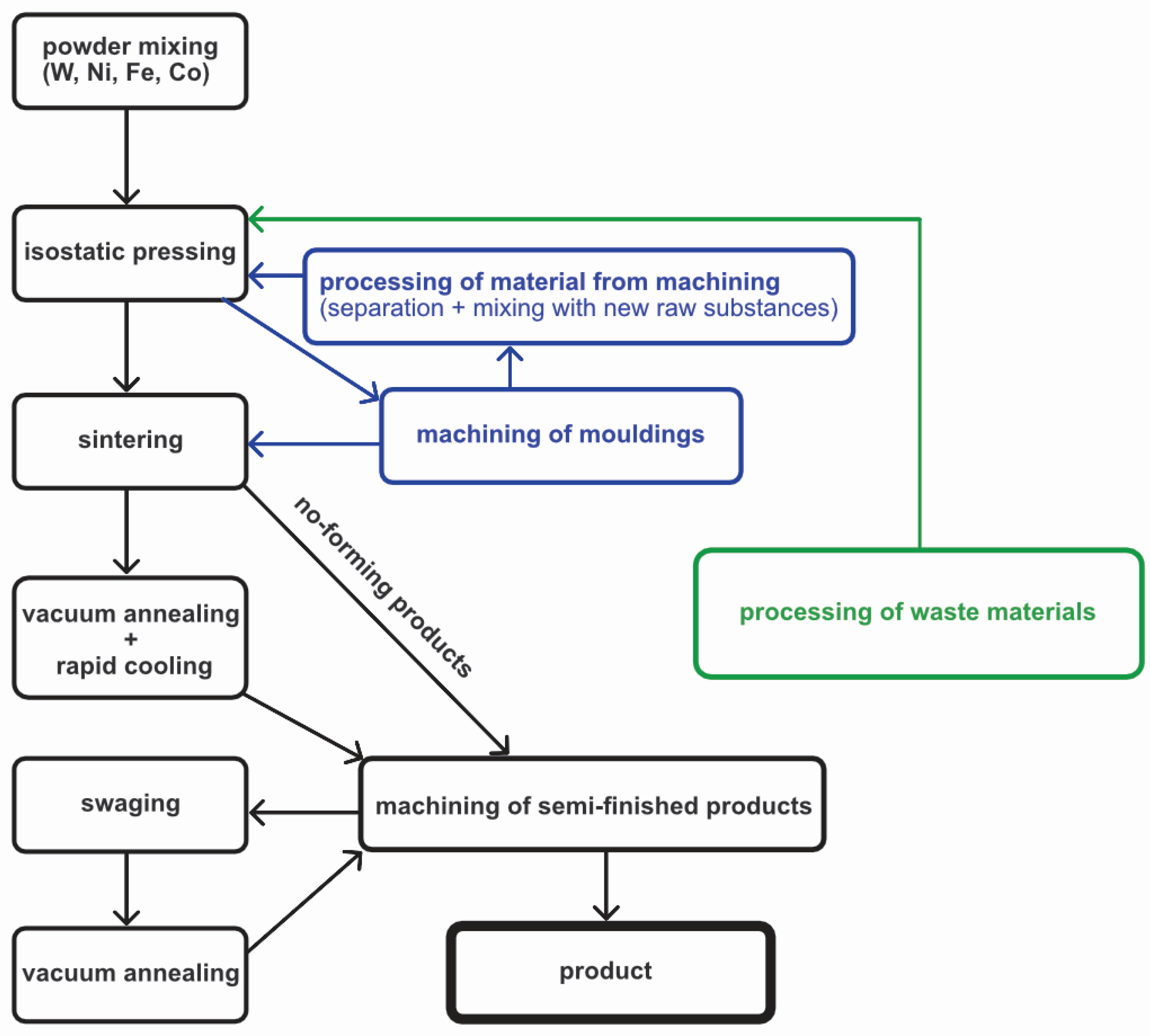
The manufacturing process of selected W-MMC composite materials is shown in
Figure 1. It breaks down into three logical technological units—the moulding preparation node, the node of high-temperature metallurgical operations (sintering, quenching, annealing), and, in our case, the node of recycling of waste from chip machining.
The input technological node involves the preparation/mixing of the initial powder mixture, either from primary original powders or from powders obtained through recycling, followed by filling the initial powder mixture into a suitably shaped vibrationally compacted elastomeric mould. After filling, the mould is moulded in the compression chamber of an isostatic press. After removal of the mould from the isostatic press chamber, the finished product is obtained.
The next technological node includes high-temperature and metallurgical processes. At first, the product (the pressed part) is placed in a suitable sintering furnace [
13,
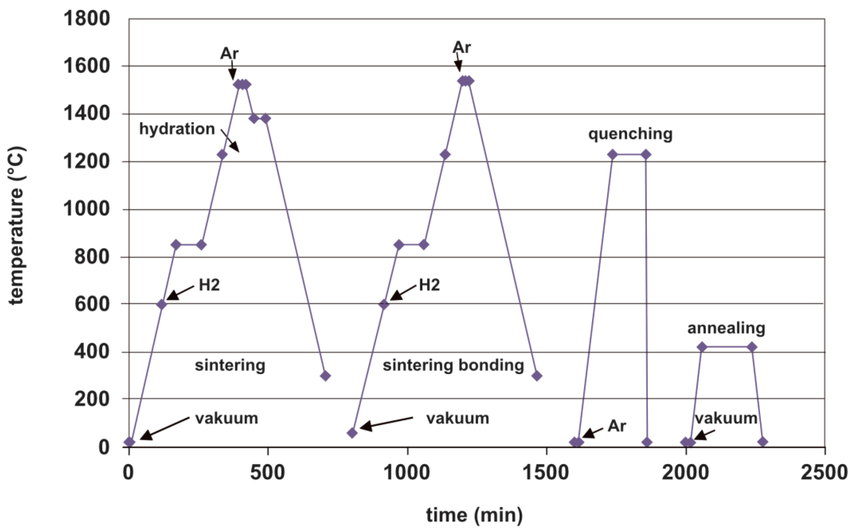
14] and, after sintering in a vacuum or protective atmosphere, annealed and quenched in water, cold or hot formed, and in the last step, aged through vacuum annealing. The sequence of operations and the characteristic temperature curves are shown in
Figure 2. The heat treatment temperature curves may vary depending on the chemical composition of the composite materials.
W-MMC composite materials can be divided into two basic groups based on the initial raw materials used. The first group consists of materials made from new powders. In contrast, the second group consists of materials made partially or entirely from recycled powders obtained by processing the materials of the first group.
2.1. Materials Produced from New Raw Materials—TN and DS
From this group of W-MMC materials, two materials are considered for possibly substituting high-strength steel in manufacturing the flywheel rotor. The first is a material with the type designation TN, which is intended for use in the manufacturing of extremely mechanically stressed components of penetrating ammunition projectiles. The second is a material with the type designation DS, which is intended for use in the manufacturing of shielding elements of containers for the transport and storage of isotopes and/or collimation systems of radiotherapy irradiators.
The first technological node, whose last operation is removing the moulded part from the mould, is common to all types of W-MMC materials. For this reason, the manufacturing process of the selected materials will be described, starting from the sintering step.
2.1.1. High-Strength Material with Lower Tungsten Content—TN
The microstructure of the material is determined by the sintering mode of the initial powder mixture [
15,
16,
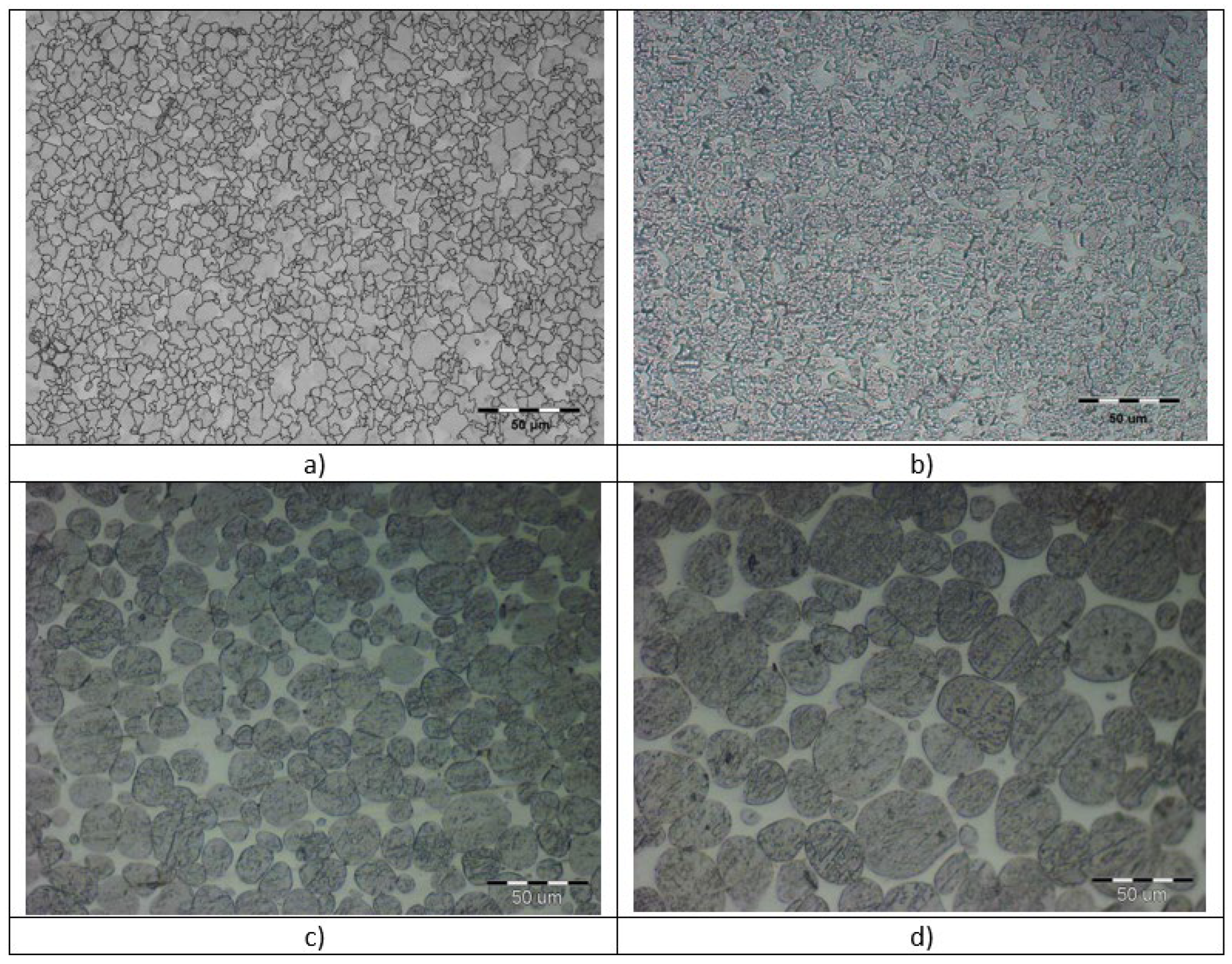
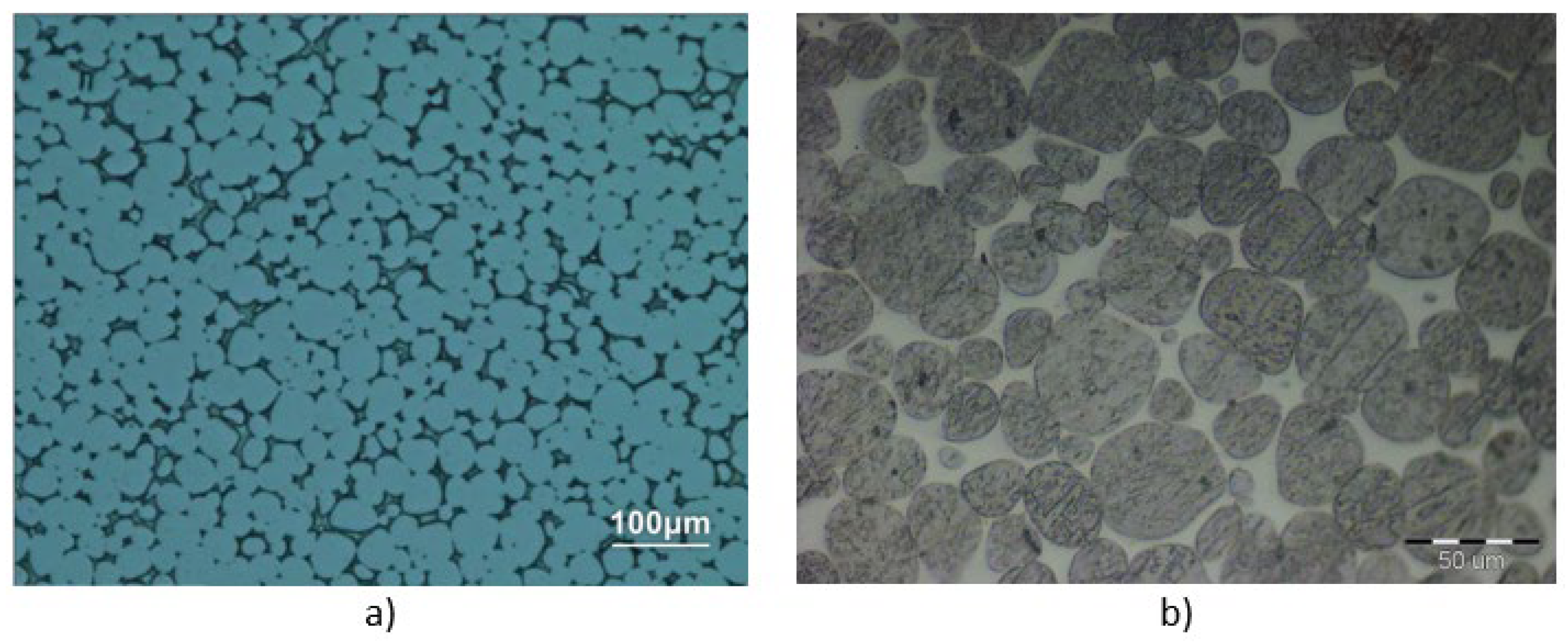
17]. The gradual evolution of the sintered microstructure during the sintering process is shown in
Figure 3. At sintering temperatures below the melting point of the impurities forming the future matrix, i.e., iron, nickel, and cobalt, a fine-grained structure of slowly growing tungsten grains is formed (
Figure 3). A gradual uniform shrinkage of the material occurs without shape deformation. However, this fine-grained structure does not allow for subsequent metallurgical processing (annealing, quenching and forming) to achieve the desired mechanical properties (strength Rm and yield strength R
p0.2) of the final TN product (R
p0.2 = R
m > 1600 MPa while maintaining ductility A
5 > 6%). It is only at sintering temperatures above the melting point of the alloying elements that the growth of spherical tungsten agglomerates (grains) in the liquid matrix consisting of Ni/Co and Ni/Co/Fe melts accelerates (
Figure 3b–d). The sinter becomes plastic, and depending on the tungsten content of the material, more or less dimensional deformation of the sinter occurs due to creep. In free sintering without a mould, significant shape deformation of the sinter occurs.
The structure’s evolution as a function of temperature and the amount of the maximum sintering temperature is shown in
Figure 3. The desired final structure of the sinter (see
Figure 3d) is composed of spherical tungsten aggregates with mean diameters in the range of 20–30 μm, which are uniformly dispersed in the “frozen” matrix.
In the next step, the sinter is annealed, followed by quenching in water. The basic quenching parameters are shown in
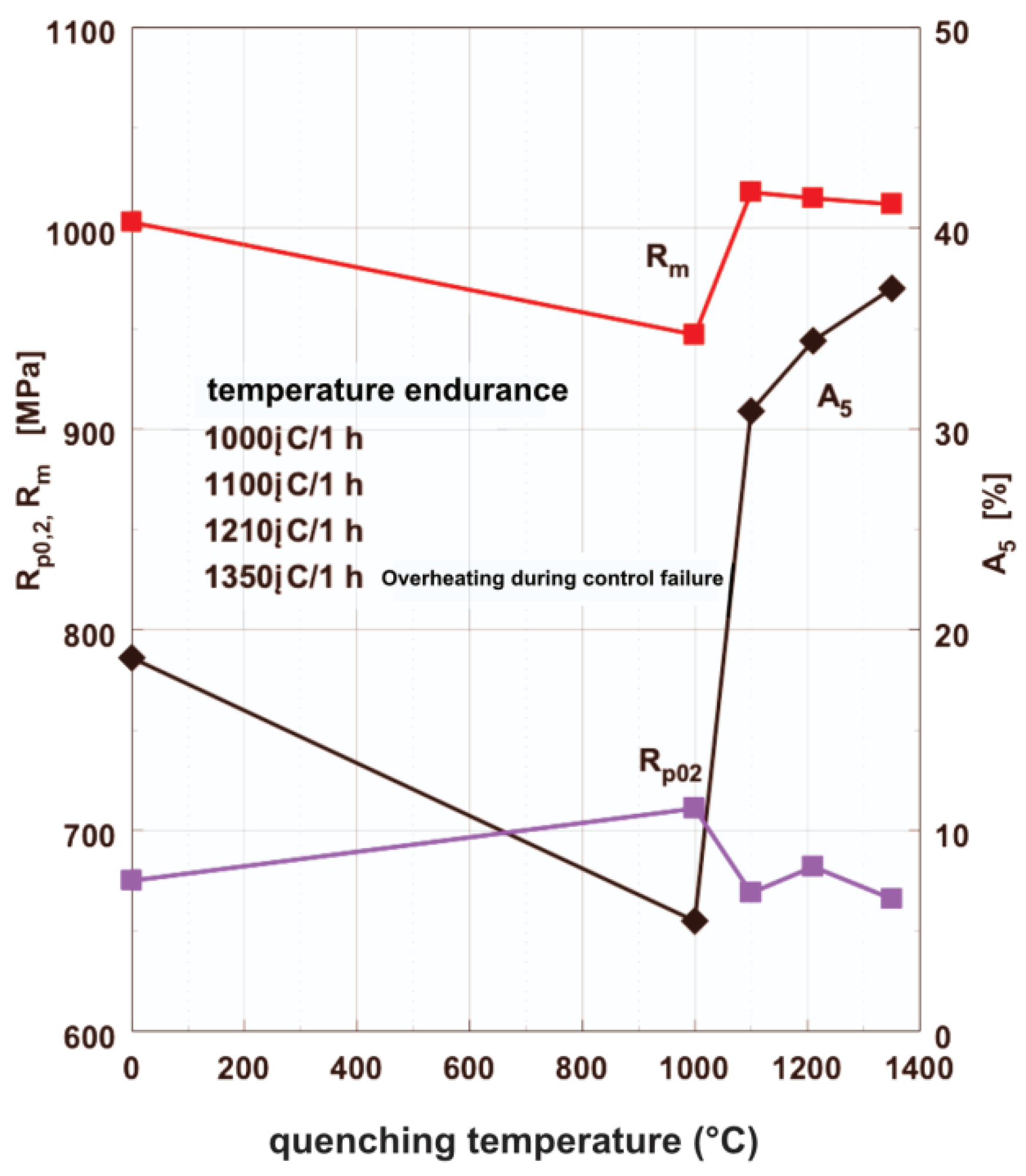
Figure 2. The typical quenching temperature is 1230 °C with a temperature endurance of one hour. Quenching removes the internal stresses at the grain boundaries between the Ni/Co matrix and the tungsten grains, and stabilises the high ductility of the A5 material, which exceeds 30% for the quenched sinter (see
Figure 4 and
Table 3). The strength Rm and yield strength R
p0.2 remain unchanged after quenching.
The strength characteristics are always the result of a tensile test on a breaking machine. Here, only one sinter sample was taken for each temperature in the graph; so, the spread of values is not visible in
Figure 4. The quenching temperature has practically no effect on the values of R
m and R
p0.2, which remain within the range of values valid for unquenched sinter. Quenching will only significantly multiply and stabilise ductility, allowing for convenient subsequent strengthening through forming. No significant changes are evident up to a quenching temperature of 1000 °C. After that, there is a high increase in ductility A5 above 30%, and this increases ever so slightly with quenching temperature. For further strengthening, a 30% ductility is sufficient and there is no point in heating the material any further.
The quenched sinter is subsequently hardened through forming. The high initial ductility of the quenched TN sinter indicates a sufficient reserve of plasticity, which allows for an increase in strength R
m = R
p0.2 > 1350 MPa with a cross-sectional reduction >30%, while maintaining sufficient residual ductility A
5 > 9% (see
Figure 5).
The last technological operation is the ageing of the forged product via annealing in a vacuum at the appropriate temperature in the range of 400–500 °C (see
Figure 2). Matching the requirements for high strength of the TN material and maintaining sufficiently high ductility requires mutual optimisation of the last two technological operations (forming and ageing) so that the resulting strength value is R
m = R
p0.2 > 1600 MPa while maintaining ductility A
5 higher than 6%, as can be seen in
Figure 6. A material with such properties is the final semi-finished product for the production of highly strength-stressed products, such as the penetrating cores of arrow-stabilised sub-calibre missiles in the military industry.
Ageing is also manifested through a change in the microhardness value of the TN material (see
Table 4).
Table 4 shows the measured microhardness values before and after the ageing of the TN material.
2.1.2. Material with Higher Tungsten Content for the Manufacturing of Shielding Elements—DS
W-MMC DS-type material has a higher tungsten content in contrast to TN material, and, thus, a higher density. It has been developed primarily for manufacturing medical components using ionising radiation, such as radiotherapy irradiators (irradiation heads and beam collimation systems) or containers for transporting and storing radioisotopes. Thus, there are no high requirements for mechanical durability; on the other hand, these parts have large dimensions and complicated shapes where the size of the press chamber of the isostatic press can be a limiting element.
The technological process as shown in
Figure 1 also applies to the DS material. The resulting microstructure of the sinter, which is shown in
Figure 7, does not show significant differences compared to the TN material, this also illustrates the similarity of the structure.
For most applications, the required mechanical properties are already achieved in the hardened sinter state; so, the process of forming is not necessary (see
Table 5). However, the high ductility values enable further strengthening of the DS material through forming if the method of final use requires it.
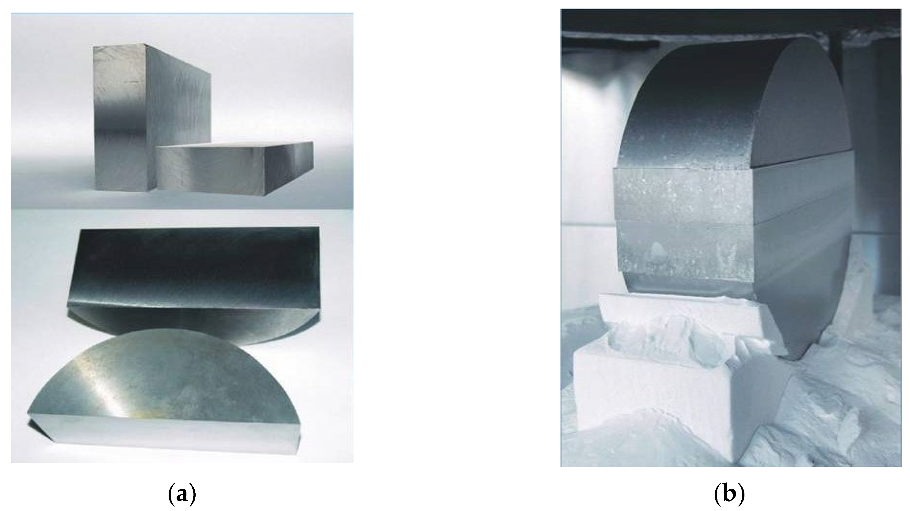
In the case of semi-finished products whose dimensions exceed the capabilities of the pressing chamber of the isostatic press, an intermediate step of connecting already sintered parts through repeated sintering is included before hardening. The touching surfaces of the individual sintered parts (
Figure 8a) are machined at the points of contact, assembled into their final form in the sintering mould and re-sintered (
Figure 8b).
2.2. Materials Made from Recycled Powders (TNRC, DSRC and TRC)
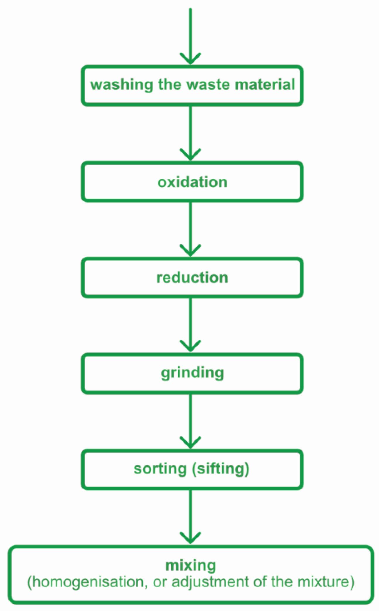
In the production of W-MMC materials, recyclable waste material is generated either before sintering, during the machining of the moulding or during the machining of the sinter at various stages of production. At present, moulding machining technology is not used. Therefore, the developed recycling technology only addresses the issue of processing waste chips from the machining of sintered TN and DS material. The basic technological scheme of oxidation/reduction chip recycling is shown in
Figure 9.
Shavings from machining are collected separately according to the type of material being machined, allowing for the recycling of material with a well-defined composition. In order to assess the possibility of using materials made from recycled powders to produce a heavy flywheel rotor, three materials were prepared. The material designated TNRC is made from powder prepared by recycling chips from TN material. Similarly, the DSRC material uses powder obtained by recycling chips from the machining of the DS material. The last material developed and tested was a material called TRC, obtained by recycling chips from the DS material but differing from the DSRC material in the way it is produced, which includes forming. A detailed description of the developed technology for recycling machining chips is beyond the scope of this paper. We will limit ourselves to an evaluation of the outputs—recycled powders.
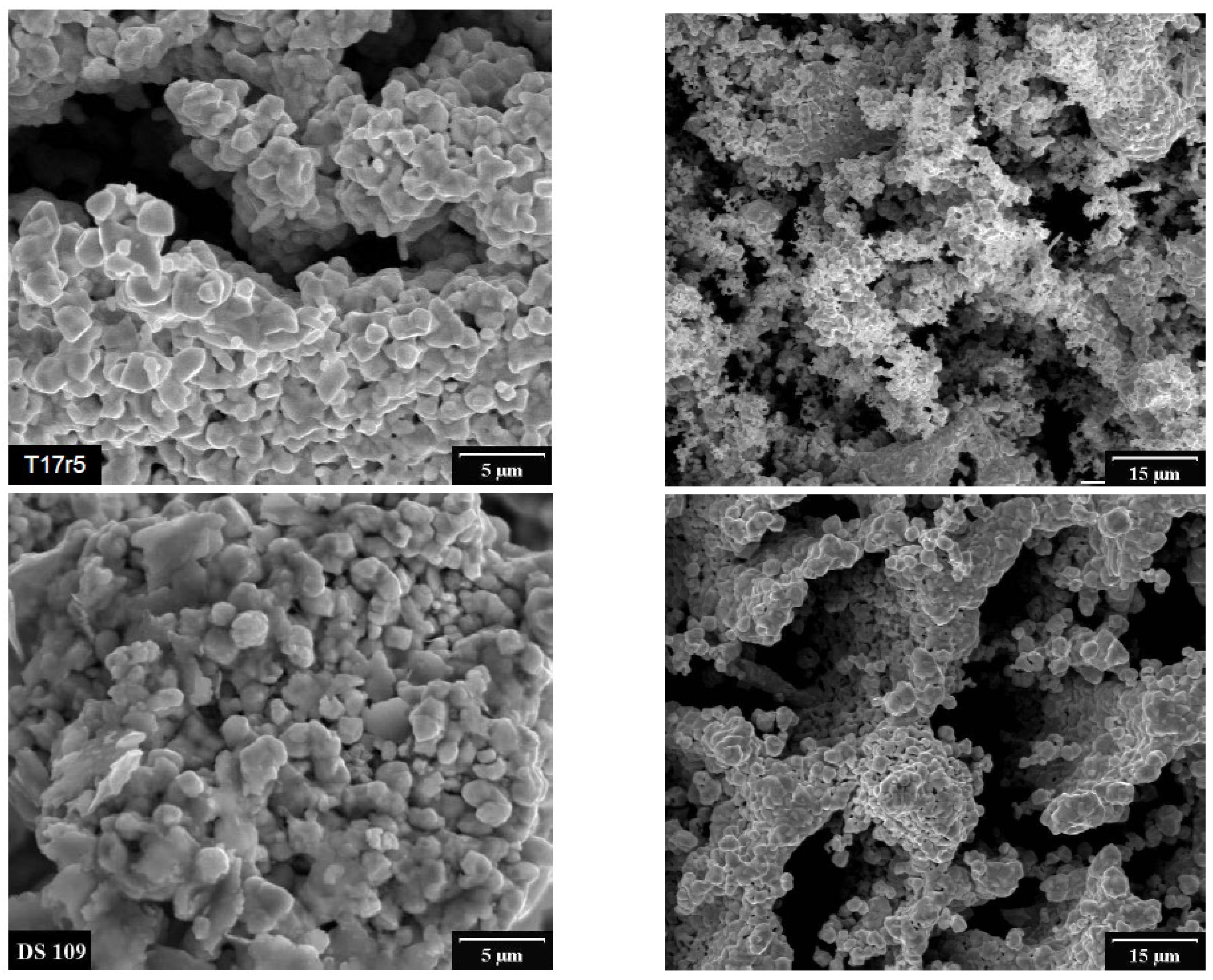
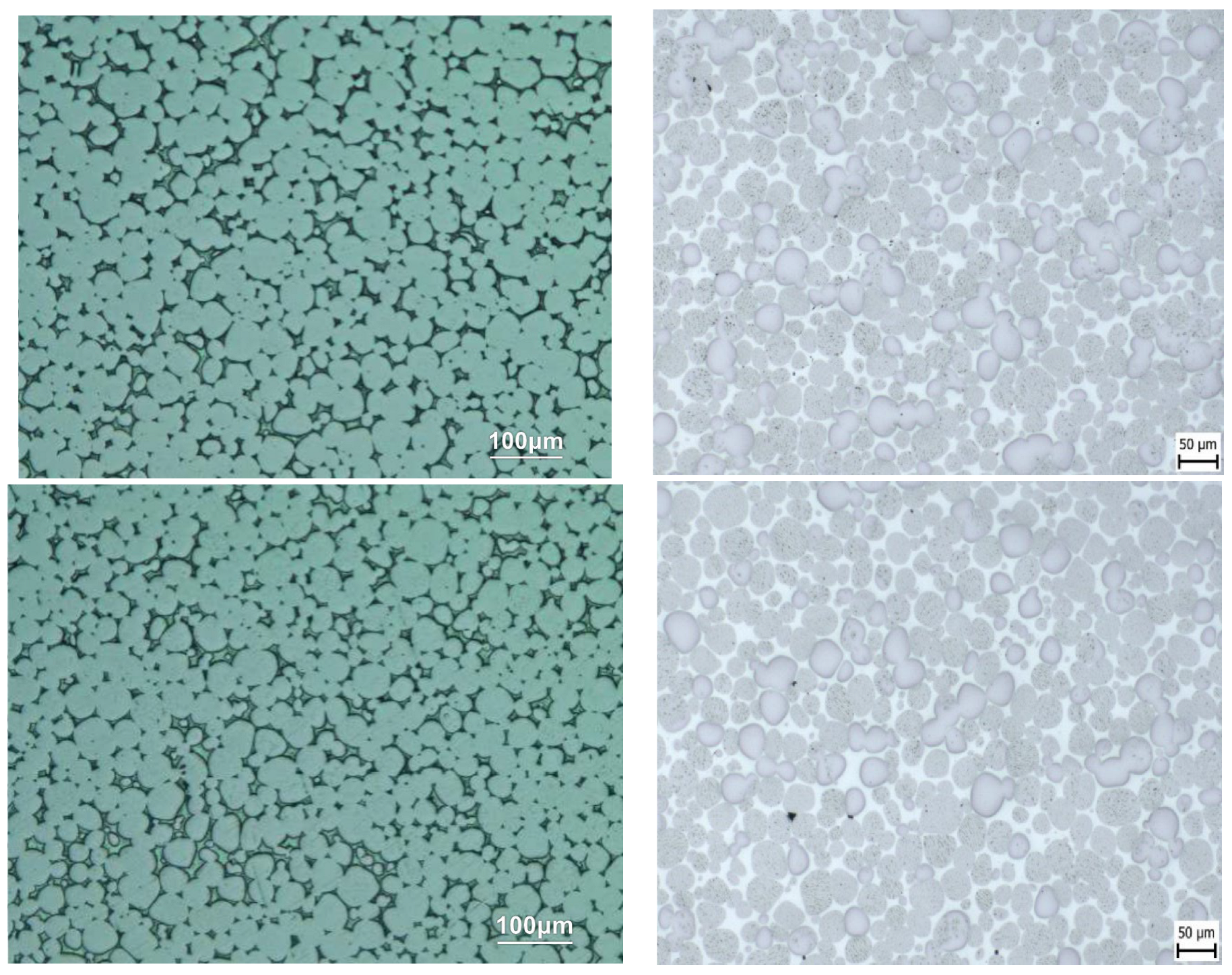
A comparison of the morphology of the recycled powder with the morphology of the original powder is made in
Figure 10. The images obtained using a line electron microscope did not show any noticeable difference even in the case of magnification.
The downstream production of W-MMC from recycled TNRC and DSRC powders followed the normal production process—the same as when using new original input raw materials. There is no difference in the cross-sections of sintered DSRC and TNRC materials prepared from recycled powder and DS and TN materials prepared from new powders (see
Figure 11).
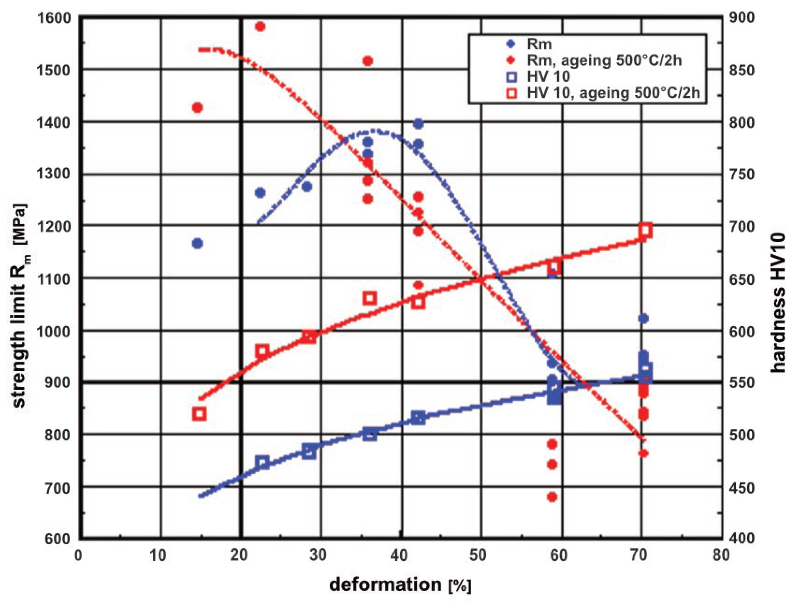
Material produced from waste can be expected to have lower and more volatile values than material produced from new feedstock. From this point of view, the mechanical properties of the DS material produced from the new powders seem to be at the lower limit of applicability for the planned use of the material for the production of flywheel rotors. Therefore, in addition to the DSRC material, a forming-strengthened material of the same composition was prepared under the designation TRC.
A relatively small forming deformation is sufficient to significantly strengthen the DSRC material, which, after subsequent vacuum annealing, i.e., ageing, gives values of R
m = R
p0.2 > 1400 MPa and of ductility <5% (see
Figure 12).
The mechanical properties of materials prepared from recycled powders at different stages of production are summarised in
Table 6.
The sensitivity of the mechanical properties of the W-MMC prepared in this way to slight contamination caused by iron of the powders obtained by recycling the chips released from the retort of the oxidation–reduction furnace during recycling was also investigated. The measurements did not show any change in the mechanical properties of the product obtained. No change in strength or ductility values was observed (see
Table 7).
3. Conclusions
In general, “heavy” flywheels are conceptually simpler and, therefore, more reliable, while high-speed “light” flywheels usually have higher specific storage capacities, tend to be more expensive and generally less reliable. This is determined by the amount of kinetic energy deposited, which is also a limiting factor for the material properties. Increasing the density of the material used places increased demands on the material strength under otherwise equal conditions, thus limiting the maximum allowable rotor speed.
For this experiment, three W-MMC materials, made from powders obtained through oxidation–reduction recycling of machining waste chips, were prepared with strength characteristics suitable for the expected use. However, only two of them have sufficient properties to be considered full replacements for steel flywheels. These materials are TNRC with strength Rm = Rp0.2 > 1600 MPa and TRC with Rm = Rp0.2 > 1250 MPa.
The substitution of steel with other metallic construction materials only makes sense if it leads to an increase in the storage capacity of the flywheel under the same conditions. A low-alloy steel flywheel in the shape of a disc made from a commercially available material with the specification DIN/EN 2CrMo4 (AISI 4142) was chosen as a basis for comparison. This steel is characterised by its toughness, good torsional strength, and good fatigue strength. It is typically used for statically and dynamically stressed vehicle components, engines and machinery, as well as for larger cross-section parts, crankshafts, and gears. The yield strength of this steel depends on the dimensions of the semi-finished product, with larger diameters reaching 500 MPa [
18].
In this case, the substitution of the flywheel material by replacing a conventional structural steel with yield strength Rp0.2 = 500 MPa with TNRC material with Rp0.2 > 1600 MPa will increase the amount of stored energy per unit mass by 36%. However, the situation is reversed when using steel with a yield strength of Rp0.2 ≥ 665 MPa.
The reason for using W-MMC material made from recycled powders for the purpose under consideration can, therefore, only be related to economic and environmental terms. However, this requires the material made from recycled powder to be comparable in price to high-strength steel and, at the same time, allow for the production of dimensionally and shape-demanding prefabricated parts, thus minimising work. Trying to make a realistic estimate of unit production costs at any given time is beyond the authors’ capabilities. However, they note that W-MMC materials made from recyclates can be seen as a relatively stable and well liquid capital investment. With their purity requirements, composition (W, Ni, Co), corrosion resistance and stability in the air, they represent a good way of storing strategic raw materials whose price is almost guaranteed not to decline and for which there will be a sustained demand.
