Article

Comparison of Degassing Efficiency on a Foundry Degassing Unit Using Different Rotor Types

1
Institute of Technology and Business in České Budějovice, 370 01 České Budějovice, Czech Republic
2
Department of Machine Designs, Faculty of Mechanical Engineering, University of West Bohemia, 301 00 Plzeň, Czech Republic
3
Die-Casting Division, MOTOR JIKOV Slévárna a.s., 370 04 České Budějovice, Czech Republic
4
Tool Shop Division, MOTOR JIKOV Fostron a.s., 370 04 České Budějovice, Czech Republic
*
Author to whom correspondence should be addressed.
Appl. Sci. 2024, 14(5), 2216; https://doi.org/10.3390/app14052216
Submission received: 9 February 2024 / Revised: 1 March 2024 / Accepted: 5 March 2024 / Published: 6 March 2024
(This article belongs to the Special Issue Recent Advances in Metallurgical Process Engineering)

Abstract

:
The present paper describes a comparison of the efficiency of different types of rotors used in the refining of aluminium melt at a foundry degassing unit (FDU). Physical modelling was used to obtain data for six different rotor types under defined experimental conditions. In order to evaluate the data from the physical model, an evaluation method based on the interpolation of degassing curves was developed in such a way that the resulting characteristic can be expressed by a single parameter. Using the new methodology, the datasets were replaced by a single dimensionless parameter, a, which characterizes the rotor performance at a given gas flow rate. Based on the comparison of these performance parameters, it was possible to mutually compare the rotor efficiency depending on the selected conditions. The comparison is also demonstrated on the expected degassing time to a certain required concentration. Based on the physical model results, the study found that rotor D had the highest degassing efficiency, followed by rotors F and A. Rotors B and E had similar efficiency at a flow rate of 17 Nl·min−1. However, rotor B showed better efficiency at higher inert gas flow rates (19 and 21 Nl·min−1), while rotor E showed better efficiency at lower flow rates (13 and 15 Nl·min−1).

1. Introduction

An ever-increasing use of aluminium alloys can be observed in many industries today. Its low weight combined with good mechanical properties and long service life make aluminium the second most important construction material in various industries. Thanks to its excellent properties, aluminium is widely used, for example, in the building industry, mechanical engineering, aviation, in food processing and automotive industries, etc. This material is popular especially due to its strength-to-weight ratio, corrosion resistance and high durability [1,2,3,4]. The recyclability of aluminium alloys is a great advantage. In accordance with the principles of circular economy, great attention is focused on recycling of aluminium scrap and its reuse as a source material in the production of aluminium alloys [5,6]. Aluminium and its alloys are also suitable as matrices of composite materials. The use of aluminium in composites makes it possible to further improve the properties of composites, such as hardness and the modulus of elasticity, while reducing the density of the material at the same time [7,8].
Although substantial progress has been seen in metallurgy in recent decades, a lot of attention continues to be paid to optimization of metallurgical processes. The technology of aluminium melt refining using an inert gas is no exception, being a pivotal process in maintaining aluminium casting quality. The requirements for high quality of aluminium products stress the importance of a better understanding of the processes that occur throughout the production process. Aluminium castings have complex shapes and limited post-casting processing options such as heat treatment and High Isostatic Pressing (H.I.P) [1]. It is essential to pay attention to both the melt preparation and casting process, as they determine the final properties of the casting, especially internal homogeneity. Various paths can be taken in the research of aluminium melt refining. The first consists in research of the technology under the operational conditions of a given production plant. Another approach is the modelling method, aimed at simulating the behaviour of a real system. Provided that certain requirements are adhered to, the model can then be used to predict the behaviour of a real system after a change in various conditions [9,10]. This method enables us to study phenomena that are difficult to measure under operational conditions because the surrounding setting is more favourable than conditions during operation (e.g., temperature, melt splashes).
There are two variants of the process modelling method. The first one is physical modelling. As described in [9,10], physical modelling is usually done in scale models of operational equipment and under normal ambient conditions. In order to obtain representative results from physical modelling that can be transferred to real conditions, the physical models must be constructed according to exactly defined principles following the theory of similarity [11]. In terms of the construction of models of the studied aggregates, it is necessary to preserve geometric similarity of the model and the real object, and kinetic and dynamic similarity of the model and the real liquid. In accordance with the theory of dimensional analysis, these principles are complied with based on the principle of equality of relevant similarity criteria of the model and the studied object. The following numbers are adequate in terms of flow hydrodynamics and its properties for the construction of models of reactors used to refine aluminium melts using an inert gas: the Euler number (Eu), the Reynolds number (Re), the Froude number (Fr) and the Weber number (We). However, the Euler number is important for flows under pressure, and under conditions of intense turbulence, the Reynolds number reaches the area of self-modelling, and thus they can be neglected under certain conditions [9,10]. Nevertheless, satisfactory modelling results can also be obtained when incomplete dynamic similarity is achieved, which is the case when not all similarity criteria are complied with. In such a case, the results may be semi-quantitative to qualitative. The deviation rate from the exact model is different in each specific case. Adherence to the modified Froude number in the form of Equation (1) is essential to achieve sufficiently accurate results for a multiphase flow, which is the case of aluminium refining using an inert gas [12,13]:
F r N = ρ g · v 2 ρ l · g · L
where ρg—gas density (kg·m−3), ρl—liquid density (kg·m−3), g—acceleration due to gravity (m·s−2), L—liquid height in the model (m), v—gas injection velocity (m·s−1). Provided that the above-described conditions are met, the obtained data can be used to set real equipment in a production plant [9,10].
The second option consists of numerical modelling. Numerical modelling of the aluminium melt refining process with argon using a submersible rotation device is complex. The refining process is composed of multiple processes (a multiphase turbulent flow, transfer of mass and energy, etc.) which are described by their governing differential equations. An effective alternative of mathematical modelling using special software can be used to simulate and predict the aluminium melt refining process. Numerical modelling of flows and other phenomena such as heat and mass transfer, the course of chemical reactions, etc., is generally called computational fluid dynamics (CFD) [14].
Many authors have focused on aluminium melt refining thanks to the prevailing popularity of aluminium as a construction material [15,16,17,18,19,20,21,22,23]. This technology includes various modifications whose history has been described by [24]. Currently, refining by inert gas using a submersible rotation device, called a foundry degassing unit (FDU), is used to refine the aluminium melt and reduce the content of hydrogen and other impurities [9,25,26]. The submersible device is composed of a hollow shaft and a rotor that blows the refining gas into the melt. Refining efficiency can be affected by many parameters, including the shape and position of the refining rotor, the rotational speed, the refining gas flow, etc. In this regard, physical modelling provides more possibilities for studying the processes and laws occurring in the volume of a vessel when aluminium is replaced with a model liquid.
The scientific basis of aluminium melt refining technology using a rotational device has been established in previous studies [27,28]. As determined by the authors of those studies, refining efficiency is largely dependent on the size of the bubbles of the gas being blown in. This size affects the size of the phase interface and thus also the transfer of mass [13,29]. Moreover, smaller bubbles are slower in reaching the surface of the liquid, and thus their residence time in the liquid becomes longer. It has been determined that the required bubble parameters are best achieved using rotational degassing. Using a nozzle or a porous block, columns of large bubbles are obtained, and these bubbles rise to the surface above the blowing point. The rotor converts energy from the propelling device to kinetic energy and transfers this energy to the melt [30]. When rotational degassing is used, the rotor creates fine bubbles of inert gas and mixes these bubbles with the melt. These fine bubbles are homogeneously distributed in the ladle volume without disturbing the surface of the melt, thereby maximizing the phase interface between the gas and the melt. The way in which gas bubbles disintegrate in a mixing vessel with a rotor was investigated in studies [31,32,33]. As determined by the authors of those studies, the mechanism of bubble fragmentation involves several steps: bubble transport to the zone behind the rotor blade due to a pressure gradient; compression and elongation of the bubble due to vortices; and bubble fragmentation through the action of high shear and tension due to the effects of the vortices on the bubble. The shape of the bubbles before disintegration indicates that vortex structures in the vessel are largely involved in this process. The authors also confirmed that the gas flow has an impact on bubble size, which increases with increasing gas flow and decreasing rotor rotational speed [31,34,35]. Bubble dispersion as a function of rotor speed was explored in [36]. As found in that study, the bubble size increases with increasing rotational speed of the rotor. This occurs due to bubble coalescence in the course of their journey through the vessel towards the surface of the liquid [37,38]. As shown by the authors of [39], the bubbles collide at a certain distance from the rotor, and their size increases due to coalescence. On the other hand, the growth rate of the bubble size slows down with rising revolutions of the rotor because the turbulent field prevents bubble coalescence [9,38].
As previously shown in many studies [15,33], the overall efficiency of refining can be influenced by the rotor shape. The kinetics of the aluminium melt refining process in a mixing vessel was studied by the authors of [16,21]. The authors carried out physical and numerical modelling in order to describe the kinetics of degassing and to compare various rotor types. As shown by numerical modelling [16], all tested rotors exhibited certain flow similarities. The fluid is pushed out of the rotor in the radial direction thanks to the momentum transmitted by the rotor and the flow of the gas. Two circulation loops thus form in the ladle—below and above the line of the rotor, while the upper circulation loop creates a weak flow, meaning that poor circulation is achieved in the upper part of the vessel [20,36]. “Dead volumes” thus form near the surface of the metal melt, which do not react with the injected gas [23]. Furthermore, as reported in [21], the efficiency of degassing is derived from the so-called pumping effect, which is created in the form of a pressure drop below the rotor that balances the centrifugal forces. The pumping effect causes the development of a vortex in the lower part of the ladle under the rotor and affects its size. Bubble dispersion depends on the capability of the rotor to push out the liquid in the radial direction and is related precisely to the pumping effect and the capability of the rotor to transmit the momentum to the liquid. The pumping effect and the transmitted momentum also play a role in the development of turbulence in the vessel; this turbulence then supports bubble fragmentation and the transfer of mass [21,31]. As reported in [23], the highest intensity turbulence was situated near the bottom of the ladle, near the vortex below the rotor, i.e., in an area directly affected by the presence of the rotor. This indicates that degassing largely occurs in the area of the rotor where the highest level of turbulence and the highest concentration of the refining gas are found. These variables can be influenced precisely by the shape of the rotor [21]. Furthermore, as shown by the results of the turbulent field calculation, higher refining gas flows are vigorously attenuated by speed fluctuations and by the turbulent flow formed in the vessel [23]. The intensity of refining is also affected by rotor speed. With a constant flow of the gas and higher speed, the bubbles exhibit smaller dimensions compared to a situation with lower speed [36,40]. On the other hand, coalescence becomes easier with higher turbulence and the bubble dimensions increase again [36].
To a certain extent, these findings are confirmed by the results of [41,42,43], where the authors performed physical modelling of the aluminium melt refining process with various flow rates of the refining gas and rotor revolutions. As shown by the results, the oxygen content in the water decreases with increasing gas flow only up to a certain value. Above this limit, an adequate increase of degassing intensity is no longer observed, and the use of higher gas flows in industrial conditions would have an adverse impact on the process economics. Increasing rotor revolutions can be approached in a similar manner.
In the context of physical modelling, the interpretation of measured results can be approached in various ways based on the measurement methods. In the scope of the research presented in this paper, a methodology of evaluating data from physical modelling was developed [44], based on interpolation of concentration curves measured in a physical model. A substitute plane was constructed using a set of concentration curves for a single rotor, constant gas flow and varying rotor rotational speeds. Considering its decreasing nature, the plane could be replaced with an exponential function where the area parameter a was the only unknown quantity. The best fitting parameter a was then found using Matlab. As a consequence, the data for one rotor type were reduced to five values while preserving the predictive performance, which made the evaluation process much simpler. The purpose was to reasonably simplify large datasets of the results in order to evaluate and facilitate the comparison of the efficiency of the rotor under various conditions.
Physical modelling was carried out as part of research focused on optimization of the refining technology used at the foundry MOTOR JIKOV Slévárna a.s. with the aim to improve the aluminium casting quality [12,42,45]. Several rotors of different shapes were studied during the modelling process. This study aims to assess the effectiveness of six different commercially available rotors used in operational conditions for aluminium degassing. A methodology for evaluating data from physical modelling was utilized to compare rotor efficiency and verify the impact of the inert gas flow rate on the degassing process. The results of the evaluation will be crucial when selecting variants for rotor testing in operating conditions.

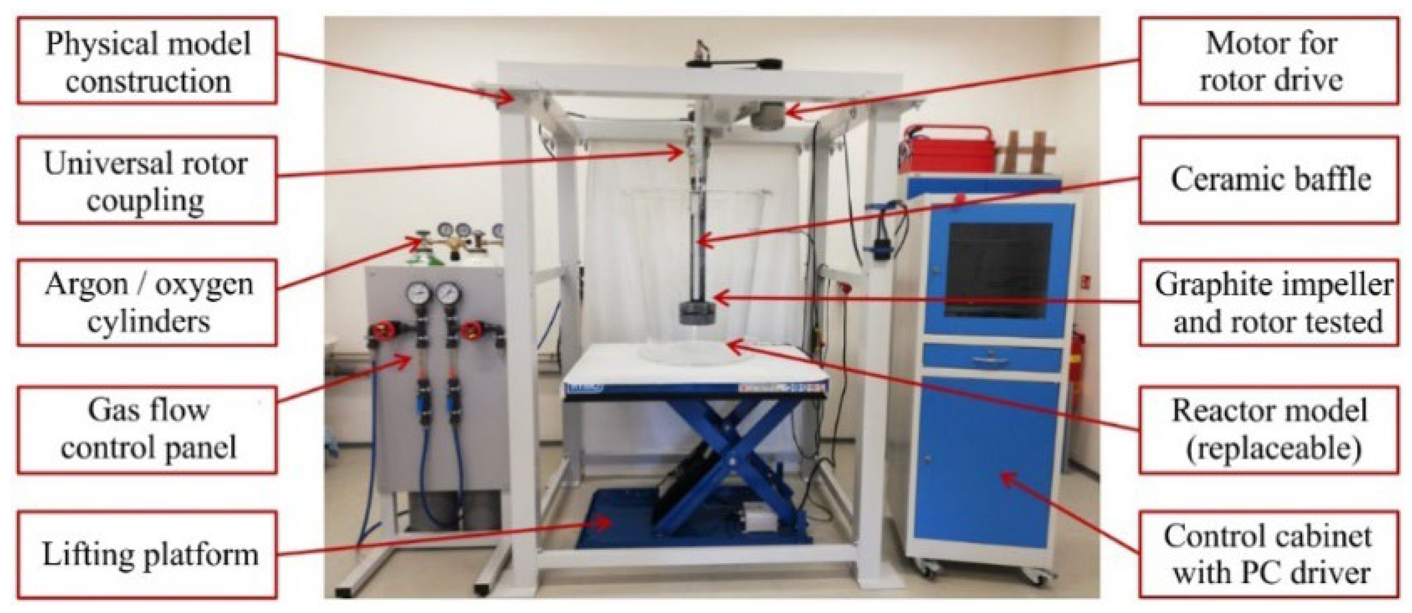
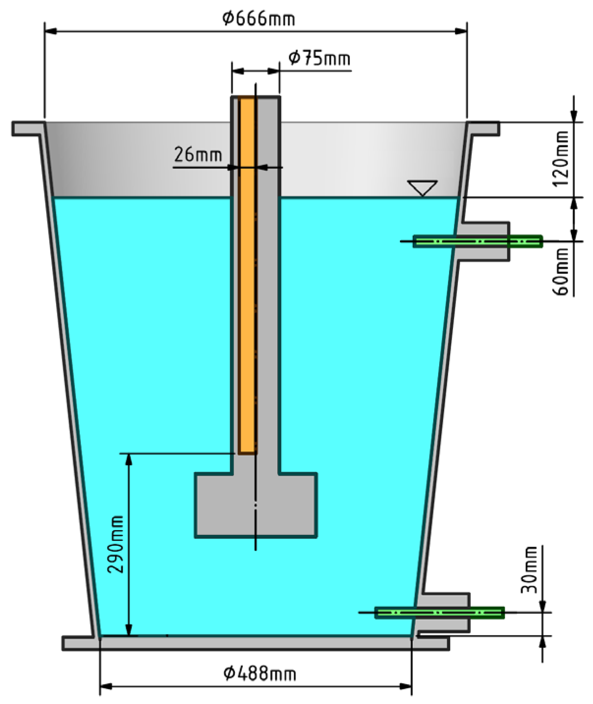
2. Experimental Procedure

Experimental measurements were made using a self-developed water-based physical model of the FDU, illustrated in Figure 1, which includes a description of the individual components. The dimensions of the physical model of the aluminium refining ladle are shown in Figure 2. The model was constructed in the scale 1:1 while observing dynamic and kinematic similarity as described in detail in [42]. The actual system of aluminium, hydrogen and nitrogen as the refining gas was replaced with water, oxygen and argon. These model media achieve similar values at 20 °C as the actual media at the operating temperature [9]. A comparison of the properties of the media is provided in Table 1. The basic principle of physical modelling of dissolved hydrogen removal from the aluminium melt was thus represented by dissolved oxygen removal from water using argon. InPro6860i/12/120/mA Ex optical probes by METLER-TOLEDO (Greifensee, Switzerland), including their components allowing the measurement of dissolved oxygen content up to 26 mg∙L−1 (26 ppm), were chosen for continuous measurement of the oxygen content. In order to maintain measurement accuracy, we regularly calibrated the probes with the special iLink-RS485/VP8 device by METLER-TOLEDO (Greifensee, Switzerland), which contains ambient pressure and relative humidity sensors. The measurement accuracy of the probes is ±1%. A system had to be developed for the probes, which would comply with the requirements for oxygen concentration measurement including communication via a PC, data archiving and data evaluation. A more detailed description of the model design and the measurement methodology is available in [42]. The measurement methodology consisted of the following steps:
  • Establish the required position of the vessel using a lifting platform in order to ensure the adequate working height of the rotor;
  • Fill the model with water; the water level reaches a height of 720 mm from the upper edge of the vessel;
  • Set the required gas flow according to the requirements of the given experiment variant while keeping a gas pressure of 0.4 bar;
  • Establish saturation with oxygen to the value of 18 ppm with the rotor rotational speed of 350 rpm and gas pressure of 0.4 bar. This is followed by a delay of 120 s; during this time, the oxygen saturation runs down, the oxygen concentration becomes homogenized in the water volume and stabilized at the required value of 22 ppm. The rotor speed is off during this delay period;
  • Set the required rotor speed for the given experiment variant;
  • Start the measurement after the delay period (start argon blowing, rotor speed and recording of data from the optical probes at the same time);
  • Stop the measurement (switch off the rotor and stop the gas feed) as soon as the mean oxygen concentration from the measuring probes reaches 0.5 ppm.
Figure 1. Description of physical model workspace.
Applsci 14 02216 g001
Figure 2. Dimensional diagram of the vessel.
Applsci 14 02216 g002
Table 1. Comparison of the parameters of the media used.
ParametersUnitIndustryPhysical Model
TemperatureK993293
Inert gas-NitrogenOxygen
Liquid-AluminiumWater
Densitykg·m−32.3450.998
Dynamic viscosityPa·s10051000
Surface tensionN·m−10.8680.072
Froude’s number-0.1210.121
This study evaluated 6 different types of rotors. Each rotor is composed of a shaft and an impeller as illustrated in Figure 3a. The studied impellers are shown in Figure 3b. The rotor is connected to the shaft by a threaded connection, or the rotor and shaft are made as a monoblock, as is the case with rotors D and E. Impellers A, B and E are circular with diameters of 190 mm. The height of rotor A is 115 mm and its upper part is indented. The design of impeller E is very similar; this impeller differs in its height (81 mm) and shaft coupling. Impeller B with a height of 105 mm has circumferential protrusions. Impeller C is star-shaped with a diameter of 192 mm and height of 90 mm. The most complex shape is shown by impeller D with an external diameter of 192 mm and height of 80 mm. A square impeller was also tested—impeller F with a side length of 134 mm and height of 61 mm. The foundry used the manufacturer’s recommended working height for the rotors. To closely simulate operating conditions, physical modelling also adhered to these recommendations. The working height of the rotors is 150 mm from the bottom of the ladle. Impeller A is the only one whose working height is 160 mm.
It can be noted that 2 types of impellers are shown in Figure 3—propeller type and pump type. The propeller type is represented by impellers C, D and F; these impellers have blades along the circumference. The blades transmit the momentum into the liquid and disperse the gas flow from the impeller into small bubbles. The pump type is represented by impellers A, B and E. These impellers have openings along the circumference which serve to distribute the refining gas in the radial direction, into the volume of the model liquid.
Measurements were carried out using the physical model under defined conditions including 35 experiment variants for each rotor. The physical model’s measurement parameters were selected to closely match operating conditions. That is why we chose parameter ranges that are realistic for operating conditions. In collaboration with the technologists at MOTOR JIKOV Slévárna a.s., variants of physical modelling were determined. The variants included 7 different rotational speeds in the range of 275 to 425 rpm and 5 different gas flow rates in the range of 13 to 21 Nl∙min−1 for each rotor. Data from a total of 210 experiments were thus obtained and evaluated. The parameters of the experiment are shown in Table 2.

3. Data Processing

Collection and evaluation of measured data is schematically described in Figure 4. Experimental data in the form of degassing curves were obtained by measurements. These data were further normalized according to Relation (2) and processed in Matlab [18], resulting in the determination of parameter a.
c o n c . s t a n d . = e ( t · r p m . a ) ,
where: t—degassing time (s), conc.stand.—standardized concentration (1), rpm—rotor speed (rpm) and a—parameter of the replacement area, which corresponds to the given rotor and gas flow.
The function according to Relation (2) is a decreasing exponential function of time and rotor revolutions. It provides the advantage that for the time equal to zero (the beginning of degassing), it is guaranteed to be 1, and for the time approaching infinity, it approaches 0. The experimental data used for the results of this study only cover the time to t = 200 s from the beginning of degassing. Although degassing was measured after this time, the data had no essential impact on the summary results, and they are not relevant in terms of operational conditions because normally, no degassing takes place after this time. The parameters a for individual degassing curve groups are generally negative and achieve the dimension of 104 when the above dimensions of the quantities are observed. A lower absolute value of the parameter a means a greater degassing capability of the rotor. Other possibilities of reduction were also tested; according to [44], replacement of the group of the curves with Relation (2) has proven to be most effective provided that a small deviation of experimental data from the replacement function is observed; this deviation mostly reaches single-digit percentage values in the processed data.
Using the corresponding parameter a, the degassing time t for the required concentration can be back-calculated according to Equation (3):
t = l n c o n c . s t a n d . r p m a ,
where: t—expected degassing time (s), conc.stand.—the required resulting standardized concentration (1), rpm—rotor speed (rpm) and a—the parameter of the replacement area corresponding to the rotor and gas flow rate. For example, a standard concentration value of 0.3 means degassing of 70% of the original gas content.

4. Results and Discussion

The physical model was used to perform the measurements of the six rotor types illustrated in Figure 3. Due to the large number of results, Figure 5 visualizes only the flow and bubble dispersion in the vessel for the case with 350 rpm and gas flow rate of 17 Nl·min−1 as used in operational conditions.
The physical modelling provided concentration curves illustrating oxygen concentration loss from the model liquid. Figure 6 shows the concentration curves measured using the tested rotor types at 350 rpm and with various flow rates of the refining gas. The concentration curves were originally evaluated according to the so-called refining time. In this case, the refining time was understood as the time needed to achieve an oxygen concentration of 0.5 ppm in the water. For better clarity and simplification, the authors of this paper developed a method for evaluating the concentration curves based on a mathematical model [44]. Performance parameters of the rotors were determined for gas flow rates of 13, 15, 17, 19 and 21 Nl∙min−1. An overview of the calculated dimensionless performance parameters a according to Equation (2) is shown in Table 3.
In Figure 5, it can be seen that the gas distribution in the liquid was similar for all rotors. The highest concentration of the gas was found around the impeller from where the gas bubbles spread radially and ascended to the surface of the liquid, while being concentrated predominantly around the shaft. Rotors A, D and F were relatively good at distributing the gas throughout the ladle volume. With these rotors, the gas was dispersed all the way to the walls of the vessel. At the same time, the gas was also distributed to the area below the rotor line. However, this applied predominantly to rotors D and F. With rotors B, C and E, the gas bubbles were not distributed all the way to the wall of the vessel and so-called “dead zones” (which are the volumes in which gas bubbles appear occasionally during the experiment) were formed. With rotor C, the gas bubbles spread more to the bottom part of the ladle, below the rotor line. As regards bubble dispersion, rotors D and E provided the best results; these rotors produced smaller bubbles that were distributed throughout the liquid volume. Therefore, rotors D and E provided the highest potential in terms of degassing efficiency. In contrast, larger bubbles can be observed in rotors B, C and E. Lower degassing efficiency was expected for these rotors given the larger bubbles and poorer distribution in the liquid volume. These findings are consistent with literature knowledge [15,20,21,36,41,43,46].
For clarity and to provide context, the parameters from Table 3 are shown in Figure 7a, which shows a comparison of rotor performance, with higher efficiency being exhibited by rotors with higher values of parameter a. The evaluation of the measured data largely confirmed the assumptions determined from the visualization of the flow characteristics. The performance trend increases with increasing gas flow rates for all rotor types, which agrees with the findings of previous studies [15,20,23,33,41,43,46]. The highest efficiency, depending on the gas flow rate, was achieved by rotors D and F; these rotors also exhibited a high level of bubble dispersion throughout the liquid volume. Very similar results were obtained for rotors B and E, although rotor E provided better performance at lower gas flow rates (13 and 15 Nl∙min−1) while rotor B achieved better results at higher gas flow rates (17, 19 and 21 Nl∙min−1). The lowest values of parameter a were calculated for rotor C, where a low rate of gas bubble dispersion was observed, as well as a non-uniform distribution of the bubbles in the liquid volume.
Comparing the rotors according to their efficiency, their ranking (starting from the most efficient) is: D, F, A, followed by E and B, and finally C with the lowest rated power. As illustrated by Figure 7a, the gas flow provides a higher effect in rotors with a worse rating than those with a better rating. Furthermore, the differences between the rotors are higher at low gas flow rates than at higher flow rates. With higher gas flow rates, the bubbles become larger and they coalesce, thus decreasing the phase interface area [33,37]. This combined effect probably caused the slowing down of the degassing effect of the rotors with increasing inert gas flow rates.
As mentioned in the rotor descriptions, three propeller-type rotors (C, D, F) and three pump-type rotors (A, B, E) were tested. The evaluation results show that the two best rotors, D and F, were propeller-type rotors. As seen in Figure 3, these two rotors were the only ones which were not circular and which were the most complex. These characteristics meant that they were apparently more capable of transmitting the momentum to the model liquid. The transmitted momentum is involved in the creation of turbulence and thus affects bubble fragmentation and the transfer of mass. In contrast, rotor C was the least complexed, its shape was very compact and included only a hint of blades along the circumference. This shape was shown to provide the least efficiency. However, it should be noted that under operational conditions, rotors with more complex shapes may be subject to faster wear. This also depends on the material used to make the rotors and its interaction with the liquid metal.
The expected calculated degassing times according to Equation (3) for each rotor are shown in Table 4. Figure 7b shows a graphical representation of expected refining times. In order to compare the expected degassing times, the required final concentration and the working speed of the rotor must be selected; the final concentration of 50% with 350 rpm was taken as an example. As shown in Figure 7b, the shortest time to achieve the required degassing quality was needed by rotor D, namely 77 s with a gas flow rate of 13 Nl·min−1 and a speed of 350 rpm. Rotor F needed 87 s. However, according to Figure 7b, if the gas flow rate for rotor F increases to 17 Nl·min−1, its efficiency would be virtually identical to that of rotor D at 13 Nl·min−1, while other rotors would not achieve this performance even with the highest studied gas flow rate of 21 Nl·min−1. In the other rotors, the speed would need to be increased in addition to an increased gas flow rate to achieve this performance. As shown by Equation (3), the degassing time is inversely proportional to speed. All of these parameters were determined based on measurements with a minimum speed of 275 rpm and maximum speed of 425 rpm. The results are not experimentally supported outside this speed range, although a similar trend can be expected.

5. Conclusions

The paper evaluates the degassing performance of rotors designed for refining aluminium melt in an FDU. Extensive experiments were carried out for this purpose using a physical model, aimed at evaluating and comparing the efficiency of degassing using six types of refining rotors. Two types of results were obtained using the physical model: visualization of the flow in order to map the gas behaviour in the liquid, and curves demonstrating oxygen concentration loss from the liquid. The concentration curves were evaluated based on a previously published data-processing method using the measured performance parameters, and the evaluation was demonstrated by determining the expected degassing time for certain defined gas flow rates. Such a comparison makes it possible to compare operating parameters of various rotors and select the most suitable with respect to the degassing time or gas consumption or other operating and economic parameters. The six rotors were evaluated not only to determine their order according to performance but also to demonstrate how the performance differences can be compensated. Differences were shown in the performance of some rotors, which can be compensated by modifying the gas flow rate. Other differences were so substantial that the different capabilities of the rotors could not be compensated even by moving from the lowest to the highest flow rate. The research findings can be summarized as follows:
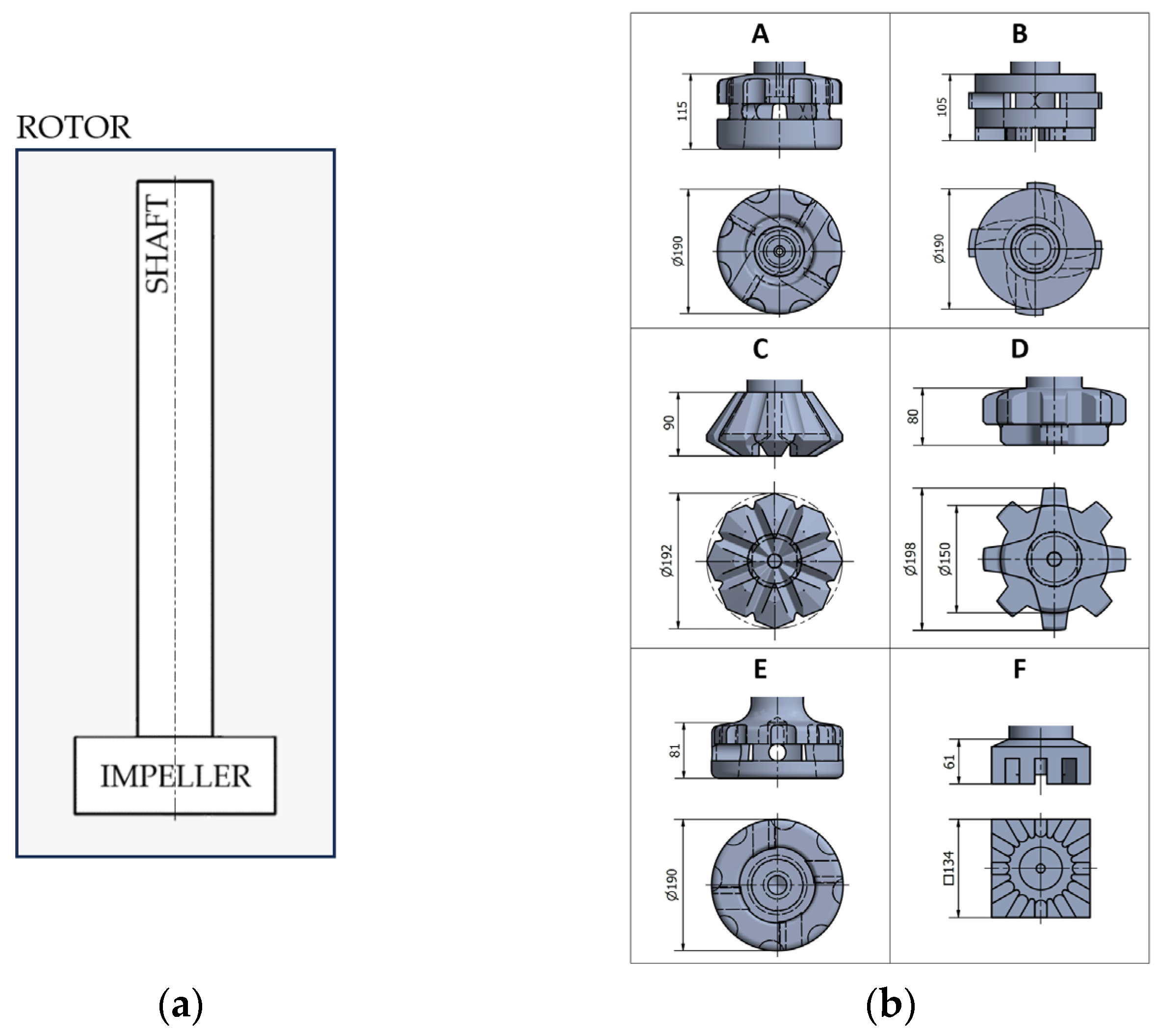
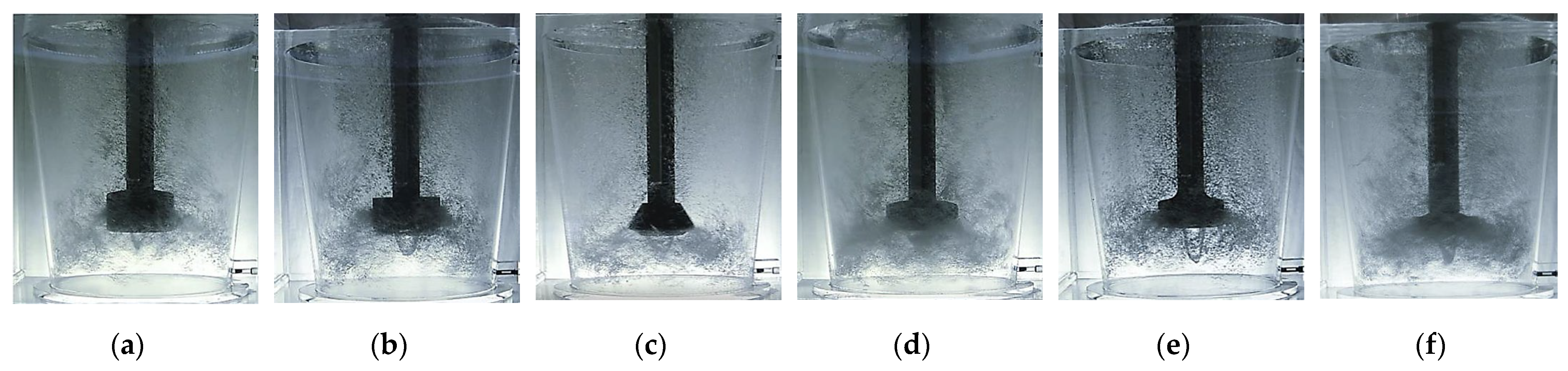
  • The gas distribution pattern in the liquid was similar for all rotors. The highest concentration of gas was found around the rotor, from where the gas bubbles spread radially and ascended to the surface, while being concentrated predominantly around the shaft. Rotors A, D and F were better in terms of distributing the gas bubbles all the way to the walls of the vessel and below the rotor line. Rotors D and E were better able to disperse the gas to fine bubbles.
  • The ranking of the rotors, evaluated based on the dimensionless parameter a, from the most efficient to the least efficient was as follows: D, F, A, E, B and C. As can be seen from the results, by changing rotor C to rotor D, the degassing efficiency can be increased by up to 45%.
  • The efficiency of the rotors corresponded well with the assumptions determined based on literature knowledge regarding the distribution and behaviour of gas bubbles in the liquid. Rotors D, F and A with higher degassing efficiency produced smaller bubble sizes and had a better ability to distribute bubbles throughout the ladle volume.
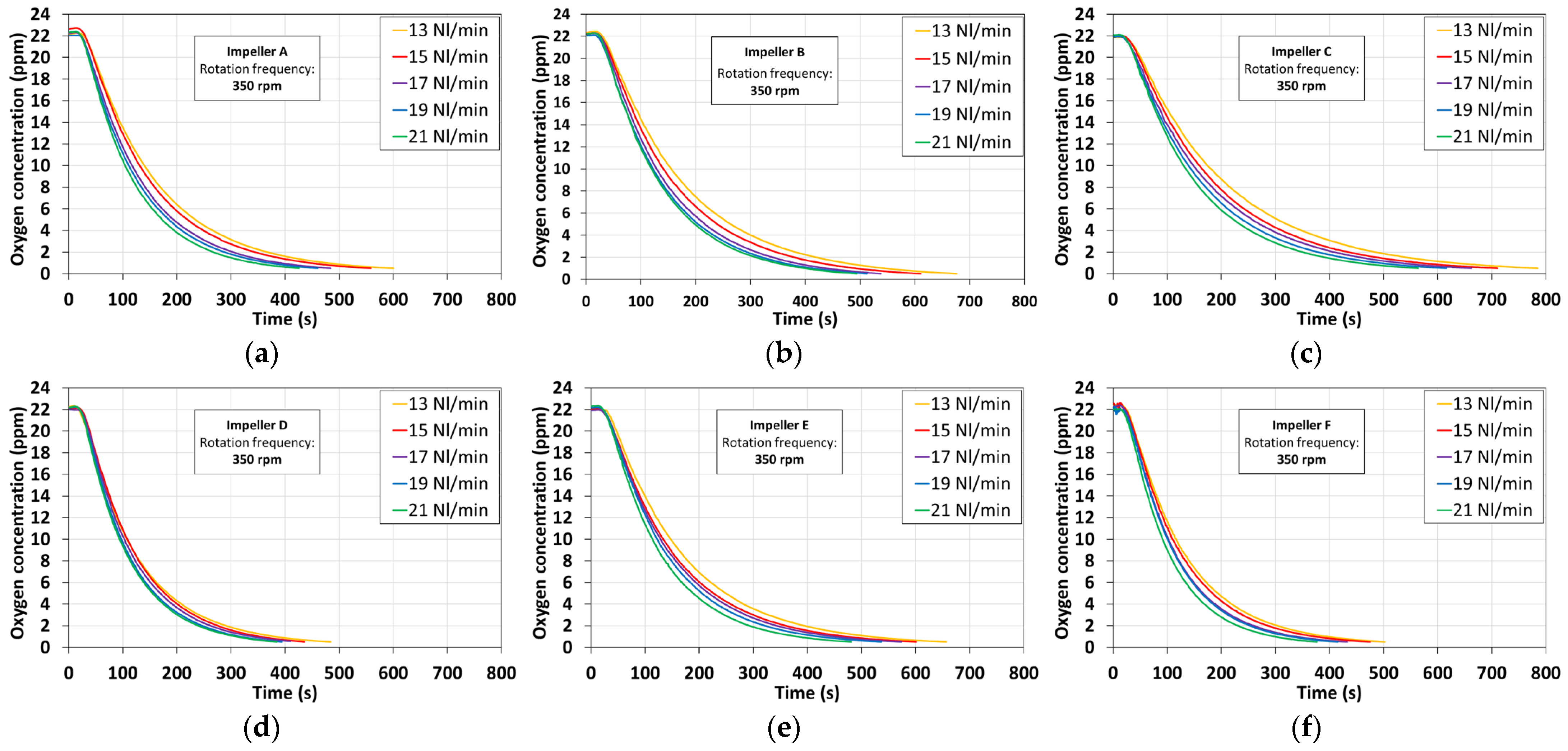
  • The degassing performance increased with increasing gas flow rates for all rotors. In the rotors with higher performance, an increase in the inert gas flow rate had a smaller effect in terms of increased degassing intensity. When the flow rate increases from 13 Nl·min−1 to 21 Nl·min−1, for rotor D the parameter a drops by 19.8%, while for rotor C, it drops by 35.1%.
  • The two best-ranked rotors (E and F) were propeller-type rotors. These rotors exhibit the highest complexity of their shape, which resulted in better transmission of the momentum to the liquid and a higher efficiency of degassing. On the other hand, in industrial conditions, rotors with complex shapes may provide a substantially shorter service life due to faster wear.
  • The dimensionless parameter a can be used to calculate the expected degassing time needed to reach any standard concentration of O2 for a given rotor speed. This enables us to obtain information about refining intensities outside the range of the measurements in this study.
In upcoming research, we will be focusing on evaluating physical modelling data to determine the impact of rotor working height and the degree of rotor wear. This knowledge will be utilized to define operational testing options for the studied rotors.

Author Contributions

Conceptualization, J.K. and J.S.; methodology, J.K. and L.S.; validation, J.K.; formal analysis, J.K.; investigation, L.S., J.S. and J.H.; data curation, J.K.; writing—original draft preparation, J.K. and J.S.; writing—review and editing, J.S.; visualization, J.K. and J.S.; supervision, T.P. and M.D.; project administration, L.S. and K.G.; funding acquisition, L.S., K.G. and T.P. All authors have read and agreed to the published version of the manuscript.

Funding

The paper was funded by the Technology Agency of the Czech Republic within the scope of the EPSILON programme, as part of the project of Reg. No. TH04010449 “Research and development of refining technologies for increasing of quality of aluminium alloys for high-performance quality castings”. This work was created with the support of Ministry of Education, Youth and Sports within the Specific university research programme in the solution of the projects reg. no. 07SVV2325 “Study of material properties and production technologies within the Environmental Research Department”.

Institutional Review Board Statement

Not applicable.

Informed Consent Statement

Not applicable.

Data Availability Statement

The raw data supporting the conclusions of this article will be made available by the authors on request.

Conflicts of Interest

Author Josef Häusler was employed by the company MOTOR JIKOV Slévárna a.s. Author Martin Dvořák was employed by the company MOTOR JIKOV Fostron a.s. The remaining authors declare that the research was conducted in the absence of any commercial or financial relationships that could be construed as a potential conflict of interest.

References

  1. Michna, Š. Encyklopedie Hliníku; Alcan Děčín Extrusions: Děčín, Czech Republic, 2005. [Google Scholar]
  2. Georgantzia, E.; Gkantou, M.; Kamaris, G.S. Aluminium Alloys as Structural Material: A Review of Research. Eng. Struct. 2021, 227, 111372. [Google Scholar] [CrossRef]
  3. Jawalkar, C.S.; Kant, S. A Review on use of Aluminium Alloys in Aircraft Components. I-Manag. J. Mater. Sci. 2015, 3, 33–38. [Google Scholar]
  4. Sun, Y. The use of aluminum alloys in structures: Review and outlook. Structures 2023, 57, 105290. [Google Scholar] [CrossRef]
  5. Cullen, J.M.; Allwood, J.M. Mapping the Global Flow of Aluminum: From Liquid Aluminum to End-Use Goods. Environ. Sci. Technol. 2013, 47, 3057–3064. [Google Scholar] [CrossRef] [PubMed]
  6. Løvik, A.N.; Modaresi, R.; Müller, D.B. Long-Term Strategies for Increased Recycling of Automotive Aluminum and Its Alloying Elements. Environ. Sci. Technol. 2014, 48, 4257–4265. [Google Scholar] [CrossRef] [PubMed]
  7. Khalid, M.Y.; Umer, R.; Khan, K.A. Review of recent trends and developments in aluminium 7075 alloy and its metal matrix composites (MMCs) for aircraft applications. Results Eng. 2023, 20, 101372. [Google Scholar] [CrossRef]
  8. Koria, C.S.; Kumar, R.; Chauhan, P.S. Reinforcement of micro and nano material with aluminum alloy (Al7075) metal matrix composite: A review. J. Phys. Conf. Ser. 2023, 2484, 012023. [Google Scholar] [CrossRef]
  9. Saternus, M. Rafinacja Aluminium I Jego Stopów Przez Przedmuchiwanie Argonem; Wydawnictwo Politechniki Śląskiej: Gliwice, Poland, 2011. [Google Scholar]
  10. Michalek, K. Využití Fyzikálního a Numerického Modelování pro Optimalizaci Metalurgických Procesů; VŠB-TU Ostrava: Ostrava, Czech Republic, 2001. [Google Scholar]
  11. Longo, S.G. Principles and Applications of Dimensional Analysis and Similarity; Springer: Cham, Switzerland, 2023. [Google Scholar]
  12. Socha, L.; Prášil, T.; Gryc, K.; Svizelova, J.; Saternus, M.; Merder, T.; Pieprzyca, J.; Nuska, P. Research on the impact of rotor wear on the effectiveness of the aluminium refining process. Sci. Rep. 2023, 13, 17758. [Google Scholar] [CrossRef]
  13. Szekely, J.; Themelis, N.J. Rate Phenomena in Process Metallurgy; Wiley: New York, NY, USA, 1971. [Google Scholar]
  14. Kundu, P.K.; Cohen, I.M.; Dowling, D.R. Fluid Mechanics; Academic Press: Cambridge, MA, USA, 2016. [Google Scholar]
  15. Kuglin, K.; Kalisz, D. Evaluation of the usefulness of rotors for aluminium refining. IOP Conf. Ser. Mater. Sci. Eng. 2021, 1178, 012036. [Google Scholar] [CrossRef]
  16. Abreu-López, D.; Amaro-Villeda, A.; Acosta-González, F.; González-Rivera, C.; Ramírez-Argáez, M. Effect of the Impeller Design on Degasification Kinetics Using the Impeller Injector Technique Assisted by Mathematical Modeling. Metals 2017, 7, 132. [Google Scholar] [CrossRef]
  17. Camacho-Martínez, J.; Ramírez-Argáez, M.; Juárez-Hernández, A.; González-Rivera, C.; Trápaga-Martínez, G. Novel Degasification Design for Aluminum Using an Impeller Degasification Water Physical Model. Mater. Manuf. Process. 2011, 27, 556–560. [Google Scholar] [CrossRef]
  18. Hernández-Hernández, M.; Camacho-Martínez, J.L.; González-Rivera, C.; Ramírez-Argáez, M.A. Impeller design assisted by physical modeling and pilot plant trials. J. Mater. Process. Technol. 2016, 236, 1–8. [Google Scholar] [CrossRef]
  19. Camacho-Martínez, J.L.; Ramírez-Argáez, M.A.; Zenit-Camacho, R.; Juárez-Hernández, A.; Barceinas-Sánchez, J.D.O.; Trápaga-Martínez, G. Physical Modelling of an Aluminium Degassing Operation with Rotating Impellers—A Comparative Hydrodynamic Analysis. Mater. Manuf. Process. 2010, 25, 581–591. [Google Scholar] [CrossRef]
  20. Gómez, E.R.; Zenit, R.; Rivera, C.G.; Juárez-Hernández, G.; Ramírez-Argáez, J.D.O.; Trápaga-Martínez, G. Physical Modeling of Fluid Flow in Ladles of Aluminum Equipped with Impeller and Gas Purging for Degassing. Metall. Mater. Trans. B 2013, 44, 581–591. [Google Scholar] [CrossRef]
  21. Abreu-López, D.; Dutta, A.; Camacho-Martínez, J.L.; Trápaga-Martínez, G.; Ramírez-Argáez, M.A. Mass Transfer Study of a Batch Aluminum Degassing Ladle with Multiple Designs of Rotating Impellers. JOM 2018, 70, 2958–2967. [Google Scholar] [CrossRef]
  22. Gómez, E.R.; Zenit, R.; Rivera, C.G.; Trápaga, G.; Ramírez-Argáez, M.A. Mathematical Modeling of Fluid Flow in a Water Physical Model of an Aluminum Degassing Ladle Equipped with an Impeller-Injector. Metall. Mater. Trans. B 2013, 44, 423–435. [Google Scholar] [CrossRef]
  23. Mancilla, E.; Cruz-Méndez, W.; Garduño, I.E.; González-Rivera, C.; Ramírez-Argáez, M.A.; Ascanio, G. Comparison of the hydrodynamic performance of rotor-injector devices in a water physical model of an aluminum degassing ladle. Chem. Eng. Res. Des. 2017, 118, 158–169. [Google Scholar] [CrossRef]
  24. Zhang, L.; Lv, X.; Torgerson, A.T.; Long, M.A. Removal of Impurity Elements from Molten Aluminum: A Review. Miner. Process. Extr. Metall. Rev. 2011, 32, 150–228. [Google Scholar] [CrossRef]
  25. Neff, D.; Sigworth, G.; Gallo, R. Melting and Treatment of Aluminum Alloys. In ASM Handbook: Aluminum Science and Technology; ASM International: Detroit, MI, USA, 2018; Volume 2A. [Google Scholar]
  26. Foundry Degassing Unit. Available online: https://www.vesuvius.com/content/dam/vesuvius/corporate/Our-solutions/our-solutions-master-english/foundry/non-ferrous-foundry/melt-treatment/brochures/FDU-e.pdf.downloadasset.pdf (accessed on 12 January 2024).
  27. Sigworth, G.K.; Engh, T.A. Chemical and Kinetic Factors Related to Hydrogen Removal from Aluminum. Metall. Trans. B 1982, 13, 447–459. [Google Scholar] [CrossRef]
  28. Sigworth, G.K. A Scientific Basis for Degassing Aluminium. AFS Trans. 1987, 95, 73–78. [Google Scholar]
  29. De Jesus, S.S.; Moreira Neto, J.; Maciel Filho, R. Hydrodynamics and mass transfer in bubble column, conventional airlift, stirred airlift and stirred tank bioreactors, using viscous fluid: A comparative study. Biochem. Eng. J. 2017, 118, 70–81. [Google Scholar] [CrossRef]
  30. Lobanoff, V.S.; Ross, R.R. Centrifugal Pumps: Design and Application; Elsevier: Oxford, UK, 1992. [Google Scholar]
  31. Yamamoto, T.; Fang, Y.; Komarov, S.V. Mechanism of small bubble breakup in an unbaffled stirred vessel. Chem. Eng. Sci. 2019, 197, 26–36. [Google Scholar] [CrossRef]
  32. Yamamoto, T.; Komarov, S.V. Single-bubble fragmentation in a mechanically stirred liquid bath under trailing vortex conditions. Online. Chem. Eng. Sci. 2019, 207, 1007–1016. [Google Scholar] [CrossRef]
  33. Yamamoto, T.; Suzuki, A.; Komarov, S.V.; Shigemitsu, M.; Taniguchi, R.; Ishiwata, Y. High Efficient Impeller for Rotary Gas Injection in Aluminum Melt. Online. Metall. Mater. Trans. B 2022, 53, 2587–2599. [Google Scholar] [CrossRef]
  34. Andersson, R.; Helmi, A. Computational fluid dynamics simulation of fluid particle fragmentation in turbulent flows. Appl. Math. Model. 2014, 38, 4186–4196. [Google Scholar] [CrossRef]
  35. Kuglin, K.; Szucki, M.; Pieprzyca, J.; Genthe, S.; Merder, T.; Kalisz, D. Physical and Numerical Modeling of the Impeller Construction Impact on the Aluminum Degassing Process. Materials 2022, 15, 5273. [Google Scholar] [CrossRef] [PubMed]
  36. Gao, G.; Wang, M.; Shi, D.; Kang, Y. Simulation of Bubble Behavior in a Water Physical Model of an Aluminum Degassing Ladle Unit Employing Compound Technique of Rotary Blowing and Ultrasonic. Metall. Mater. Trans. B 2019, 50, 1997–2005. [Google Scholar] [CrossRef]
  37. Cao, Q.; Nastac, L. Mathematical Modeling of the Multiphase Flow and Mixing Phenomena in a Gas-Stirred Ladle: The Effect of Bubble Expansion. JOM 2018, 70, 2071–2081. [Google Scholar] [CrossRef]
  38. Liu, Y.; Zhang, T.; Sano, M.; Wang, Q.; Ren, X.; He, J. Mechanical stirring for highly efficient gas injection refining. Trans. Nonferrous Met. Soc. China 2011, 21, 1896–1904. [Google Scholar] [CrossRef]
  39. Kerdouss, F.; Kiss, L.; Proulx, P.; Bilodeau, J.-F.; Dupuis, C. Mixing Characteristics of an Axial-Flow Rotor: Experimental and Numerical Study. Int. J. Chem. React. Eng. 2005, 3. [Google Scholar] [CrossRef]
  40. Kang, Y.Y.; Lin, Y.; Liu, X.D.; Sun, C.; Yuan, S.S.; Zuo, Y.B.; Cui, J.Z. Study on the High Shear Degassing Process with Water Simulation. Adv. Mater. Res. 2015, 1120, 1214–1219. [Google Scholar] [CrossRef]
  41. Saternus, M.; Merder, T. Physical Modeling of the Impeller Construction Impact on the Aluminum Refining Process. Materials 2022, 15, 575. [Google Scholar] [CrossRef] [PubMed]
  42. Prášil, T.; Socha, L.; Gryc, K.; Sviželová, J.; Saternus, M.; Merder, T.; Pieprzyca, J.; Gráf, M. Using Physical Modeling to Optimize the Aluminium Refining Process. Materials 2022, 15, 7385. [Google Scholar] [CrossRef] [PubMed]
  43. Saternus, M.; Merder, T. Physical Modelling of Aluminum Refining Process Conducted in Batch Reactor with Rotary Impeller. Metals 2018, 8, 726. [Google Scholar] [CrossRef]
  44. Kolínský, J.; Prášil, T.; Socha, L.; Gryc, K.; Sviželová, J.; Dvořák, M.; Nuska, P. Processing of Experimental Data from Physical Model of the FDU Refining Unit. In Proceedings of the METAL 2023: 32nd International Conference on Metallurgy and Materials, Brno, Czech Republic, 17–19 May 2023. [Google Scholar]
  45. Prášil, T.; Socha, L.; Gryc, K.; Sviželová, J.; Saternus, M.; Merder, T.; Pieprzyca, J.; Gráf, M. Impact of Rotor Material Wear on the Aluminum Refining Process. Materials 2022, 15, 4425. [Google Scholar] [CrossRef]
  46. Walek, J.; Michalek, K.; Tkadlečková, M.; Saternus, M. Modelling of Technological Parameters of Aluminium Melt Refining in the Ladle by Blowing Inert Gas through the Rotating Impeller. Metals 2021, 11, 284. [Google Scholar] [CrossRef]
Figure 3. View and main dimensions (mm) of tested impellers. (a) Rotor parts; (b) 3D view and marking of tested impellers.
Applsci 14 02216 g003
Figure 4. Data collection and evaluation scheme.
Applsci 14 02216 g004
Figure 5. Demonstration of the character of the internal flow and distribution of the bubbles of inert gas; gas flow rate: 17 Nl·min−1, rotor speed: 350 rpm; (a) rotor A; (b) rotor B, (c) rotor C, (d) rotor D, (e) rotor E, (f) rotor F.
Applsci 14 02216 g005
Figure 6. Demonstration of the concentration curves obtained by physical modelling; gas flow rate: 17 Nl·min−1, rotor speed: 350 rpm; (a) impeller A; (b) impeller B, (c) impeller C, (d) impeller D, (e) impeller E, (f) impeller F.
Applsci 14 02216 g006
Figure 7. (a) Graphical representation of performance parameter a; (b) graphical representation of predicted degassing time.
Applsci 14 02216 g007
Table 2. Parameters of experiments on the physical model.
Working heightmm150/160
Rotor speedrpm275, 300, 325, 350, 375, 400, 425
Ar flow rateNl∙min−113, 15, 17, 19, 21
Table 3. Values of performance parameters a depending on refining conditions.
Parameter a·103
Gas Flow Rate(Nl∙min−1)1315171921
Rotor typeA(1)−51.6−48.2−44.4−42.3−41.0
B(1)−57.3−54.0−49.0−46.0−45.5
C(1)−70.4−64.2−60.1−56.7−52.1
D(1)−38.7−36.2−34.6−33.3−32.3
E(1)−55.8−52.2−49.3−46.5−43.3
F(1)−43.9−41.5−38.2−37.4−34.5
Table 4. Prediction of degassing time depending on the conditions of refining (resulting standard concentration: 50%, rotor speed: 350 rpm).
Parameter Degassing Time
Gas Flow Rate(Nl∙min−1)1315171921
Rotor typeA(s)10295888481
B(s)113107979190
C(s)139127119112103
D(s)7772696664
E(s)110103989286
F(s)8782767468
Disclaimer/Publisher’s Note: The statements, opinions and data contained in all publications are solely those of the individual author(s) and contributor(s) and not of MDPI and/or the editor(s). MDPI and/or the editor(s) disclaim responsibility for any injury to people or property resulting from any ideas, methods, instructions or products referred to in the content.

