Article

A Study on the UWB-Based Position Estimation Method Using Dead Reckoning Information for Active Driving in a Mapless Environment of Intelligent Wheelchairs

Department of Electronic Engineering, Tech University of Korea, Siheung 15073, Gyeonggi, Republic of Korea
*
Author to whom correspondence should be addressed.
Appl. Sci. 2024, 14(2), 620; https://doi.org/10.3390/app14020620
Submission received: 4 December 2023 / Revised: 9 January 2024 / Accepted: 9 January 2024 / Published: 11 January 2024
(This article belongs to the Special Issue Rehabilitation and Assistive Robotics: Latest Advances and Prospects)

Abstract

:
As the world enters an aging and super-aged society, the application of advanced technology in assistive devices to support the daily life of the elderly is becoming a hot issue. Among them, electric wheelchairs are representative assistive devices for the walking support of the elderly, and their structural form is similar to AGV and AMR. For this reason, research is being introduced and underway to guarantee the right to voluntarily move or improve the convenience of movement for the elderly and severely disabled people who have difficulties in operating a joystick for operating an electric wheelchair. Autonomous driving of mobile robots is a technology that configures prior information on the driving environment as a map DB and operates based on it. However, active driving assistance technology is needed because wheelchairs do not move in a limited space, but can move to a place without a prior map DB or vehicle boarding depending on the passenger’s intention to move. Therefore, a system for estimating the moving position and direction of the wheelchair is needed to develop a driving assistance technology in the relevant driving environment. In order to solve the above problem, this study proposes a position and direction estimation algorithm suitable for active driving of a wheelchair based on a UWB sensor. This proposal is an algorithm for estimating the position and direction of the wheelchair through the fusion of UWB, IMU, and encoder sensors. In this proposal, it is difficult to design an active driving assistance system for wheelchairs due to low accuracy, obstacles, and errors due to signal strength in the position and direction estimation with UWB sensors alone. Therefore, this study proposes a wheelchair driving position and direction estimation system that fuses the dead recording information of a wheelchair and the UWB-based position estimation technique based on sensors applied in IMU and encoders. Applying quantitative verification to the proposed technique, the direction estimation accuracy of the wheelchair of about 15.3° and the position estimation error average of ±15 cm were confirmed, and it was verified that a driving guide for active driving was possible when the sensor system proposed in a mapless environment of the wheelchair was installed at a specific destination.

1. Introduction

Since the 21st century, life expectancy has increased with the development of science and medical technology, and the aging of the population has become a social issue throughout the world due to the decline in the fertility rate due to the global economic downturn and low growth [1]. Against this social background, the silver industry, healthcare market, and care service market to support them are continuously growing. As the elderly population increases, most of them are burdened with long-distance walking due to their physical aging, and the advanced technology of assistive devices to guarantee their right to move is becoming a hot topic. Wheelchairs are used as assistive devices for those who have difficulties in walking normally due to innate or acquired reasons [2]. In response to this demand, the wheelchair market size is expected to grow by 7.40% annually to reach $9.5 billion by 2032, of which the market size of electric wheelchairs accounts for more than 50% [3]. Here, 58.9% of users of electric assistive devices such as electric wheelchairs experienced accidents, of which 34.5% were involved in crashes [4]. Although it depends on the degree of disability among people with disabilities such as cognition, movement, and sensation, they generally have difficulties in fine manipulation of the joystick used for electric wheelchair operation [5].
As a result, research is being conducted to assist wheelchair convenience and collision stability by applying it to wheelchairs due to the advancement of indoor autonomous driving technology used in AGVs (Automated Guided Vehicles) and AMRs (Autonomous Mobile Robots), which have recently become a technical topic following the advent of the fourth industry [6].
Based on research on applying the autonomous driving technology of mobile robots as wheelchairs, wheelchairs capable of autonomous driving are used to help wheelchair users move only in limited spaces such as hospitals [7]. Due to the support of wheelchairs capable of autonomous driving in indoor spaces, users who complain of difficulties in wheelchair operation can use them without any manipulation. Thus, it is a hot issue because it can prevent collisions caused by inexperience in operation [8]. However, for current autonomous driving technology, prior data are essential to actively move to the destination based on the current position through the pre-map information [9]. Therefore, the current indoor autonomous driving technology cannot utilize autonomous driving in a mapless environment because it is difficult to create a route for driving to the destination through position estimation without prior map information [10].
Unlike autonomous robots, wheelchairs are not limited to the space of use, but move various indoors/outdoors with the user’s means of transportation. Thus, there is a limit to configuring all driving environments as a map DB. Therefore, the current autonomous driving system can be used in some environments where a map exists, but it is difficult to use it in most outdoor environments and mapless environments. Therefore, current autonomous driving can support indoor movement with a map, which is the main use space for wheelchairs, but it is difficult to assist in long-distance travel or moving to other activity areas [11]. Most wheelchairs move outdoors through a vehicle that can be used for wheelchair boarding and enter and exit the building by getting in and out of the main active space, such as the entrance of the building or the entrance of the housing complex, but it is difficult to hold a map in a pre-space with high volatility and a lack of feature points, such as the entrance of a hospital or the entrance of a housing complex [12,13]. Therefore, it is difficult to apply the current autonomous driving technology in the case of active driving at the entrance of a building without prior map information. Therefore, the current self-driving wheelchair is used as an autonomous driving device in a specific building, which is difficult to support when moving to various spaces. Therefore, in order to solve the above problem, this study proposes a position and direction estimation method for driving assistance technology that guides the position and direction to the destination of the wheelchair for active driving of the intelligent wheelchair at the entrance of a space where the current autonomous driving system is difficult to apply, such as mapless environments.
Research and development of active driving assistance technology in mapless situations is being used in docking technologies such as AGVs and cleaning robots [14]. Laser guidance-based technology is a method in which a laser emitted from a robot receives a reflected laser through a reflector mounted at a specific point and estimates its position through triangulation based on the measured distance [15]. However, if there is an obstacle between the laser and the reflector, the distance cannot be measured, and the measurement accuracy is reduced due to the influence of weather such as rain and fog [16,17]. Therefore, this is not a suitable technology for intelligent wheelchairs used outdoors and in places where environmental variables occur and coexist with people. For this reason, the technology is not suitable for use as an active driving assistance technique for wheelchairs that move with people. In the case of driving assistance systems through QR codes, they are mainly used for docking technologies because of their high accuracy in close proximity compared to other technologies [18,19]. However, in the case of QR codes, the measurement distance varies depending on the measurement camera or H/W, but in general, if the measurement distance is relatively short compared to other technologies and is not perpendicular to the camera and QR code, the measurement error increases, and the QR code must be attached to the floor or ceiling, making it unsuitable for the intelligent wheelchair system targeted in this study [20,21]. In the case of a driving system through ultrasonic sensors, the ultrasonic sensor at a specific point is mounted to receive the launched data, measure the distance, estimate the position through triangulation, and use it for driving assistance technology [22]. However, it is difficult for multiple modules to transmit and receive at the same time due to the interference caused by overlapping signals from different sensors, which are strongly influenced by the measurement distance caused by obstacles in the ultrasonic sensor [23,24]. Therefore, it is not a suitable technology for use in intelligent wheelchairs because it is difficult for multiple intelligent wheelchairs to transmit and receive signals at the same time. Position estimation techniques such as Wi-Fi/Bluetooth/Zigbee and others use distance-based triangulation to calculate positions using the characteristics of constant attenuation of radio waves in space according to distance [25]. The RSSI (Received Signal Strength Indication) method has a problem of increasing position error due to difficulties in measuring accurate signal strength because of differences in the characteristics between antenna and front-end radio frequency (RF) and has lower accuracy than ToA (Time of Arrival) based on arrival time in an outdoor environment where many people exist due to low permeability [26]. Therefore, it is not a suitable technology as a position estimation system for driving assistance for intelligent wheelchairs.
Therefore, this study proposes a position and direction estimation system based on UWB (ultra-wide band) with relatively high permeability and various bandwidths to measure distance based on the arrival time of radio waves in order to solve the problem mentioned above [27]. In the case of UWB sensors, it has the advantage of being able to estimate the position regardless of changes in the topography after being installed at a fixed position, and it is being installed in various mobile devices such as mobile phones. In the future, it is expected to be able to access mobile devices without a separate installation, and because accessibility increases, it is suitable for use as a position estimation device [28]. However, the existing single UWB sensor-based estimation technology has the disadvantage that the position estimation through only UWB sensors is difficult to use as a driving assistance technology due to its low accuracy and difficulty in estimating the direction [29,30].
Therefore, it is necessary to improve the existing position and direction estimation system for the development of a driving assistance system for the wide use of autonomous driving technology of wheelchairs. In this study, sensors such as encoders and IMU that can implement position estimation are applied to reduce noise and outliers and improve positioning accuracy in the existing UWB sensor-based position estimation method. Through this, this study proposes a position and direction estimation system with a level of accuracy that can assist driving through fusion with existing UWB sensor-based position estimation data based on dead reckoning suitable for wheelchair environments.

2. Main Subject

UWB is a low-power ultra-wide band-based wireless communication technology that enables distance measurement and data transmission and reception. However, it is limited because high noise and outlier data are included to be used as position estimation for driving assistance rather than general position estimation. Therefore, to overcome these limitations, this study generally uses a single UWB sensor fused with encoder and IMU sensors, which have high accuracy when measuring at short distances, and the shortcomings of the data, including high noise and outliers, can be improved. Based on this, this study proposes a sensor fusion-based position and direction estimation system that can actively implement a driving assistance system in mapless situations for wheelchair users.

2.1. Sensor System for Active Driving Assistance

2.1.1. UWB

UWB is an ultra-wide wireless communication technology that enables distance measurement and data transmission and reception over a bandwidth of 500 Mhz or more. It is possible to measure distance through the transmission time or transmission time difference information rather than the existing RSSI method of measurement, and it is easy to use in various environments due to high obstacle permeability because it uses a measurement method through radio waves. However, when estimating positions through a single UWB sensor, the accuracy is not high because of the problem of strong outliers, due to the influence of multiple paths caused by diffraction and reflection of radio waves and noise through the transmission and reception of radio waves. Therefore, to solve this problem, various filters such as EKF are used to increase accuracy by removing outliers and noise [31,32]. However, the single sensor-based method has difficulty correcting data distortion through obstacles during driving, and it is difficult to use as a driving assistance system because delays occur when suppressing noise strongly to increase accuracy. Therefore, in this study, a UWB sensor-based position and direction estimation system suitable for a wheelchair environment is proposed. In order to solve the problem of a single UWB sensor, a position and direction estimation system for driving assistance is designed, entailing position estimation using multiple sensors rather than position estimation through a single sensor.

2.1.2. IMU

In this study, the IMU sensor was used to correct the direction data of the UWB sensor. In the case of direction estimation through the UWB sensor, data tremors caused by the radio wave reception strength and obstacles to the UWB sensor data occur, and the UWB sensor-based direction estimation can cause strong errors. Therefore, the direction estimation was corrected through angular velocity data for IMU sensors with a high short-range measurement accuracy. IMU sensors are usually mounted at the center of the robot drive shaft and used to measure the robot direction. They consist of acceleration, geomagnetic, and angular velocity sensors, and assuming that the robot moves in a plane, the angle of the robot is limited to the yaw axis, which can be calculated from angular velocity and geomagnetic sensors. However, in the case of geomagnetism, the noise caused by iron or structures that are heavily affected by the electromagnetic field is strong, and it is difficult to use when considering the electromagnetic field through the motor [33]. Therefore, the estimation in this study used only angular velocity data. However, in the case of the angular velocity data, it is difficult to know the initial direction and has a drift error in which errors accumulate over time. Therefore, in this study, the direction of improving the shortcomings through fusion with the UWB sensor was estimated.

2.1.3. Encoder

An encoder sensor was used to correct the position data of the UWB sensor applied in this study. The encoder sensor is mainly mounted on the wheel of the robot to measure the change in movement, such as the rotation of the wheel, and to calculate the speed or moving path of the wheelchair. Encoder sensor data are mainly used to calculate short-range driving routes because they have high accuracy in calculating instantaneous wheel rotation speed. Since this sensor has a relatively high short-range measurement accuracy compared to other sensors, it was used in this study to correct the position estimation error of the UWB sensor. However, the position where the data are accumulated through the encoder sensor makes it difficult to estimate the initial position and the data have a drift error in which errors due to slip and friction are accumulated. Therefore, in this study, the shortcomings were improved through fusion with the UWB sensor.

2.2. Proposed Position Estimation System for Active Driving Assistance

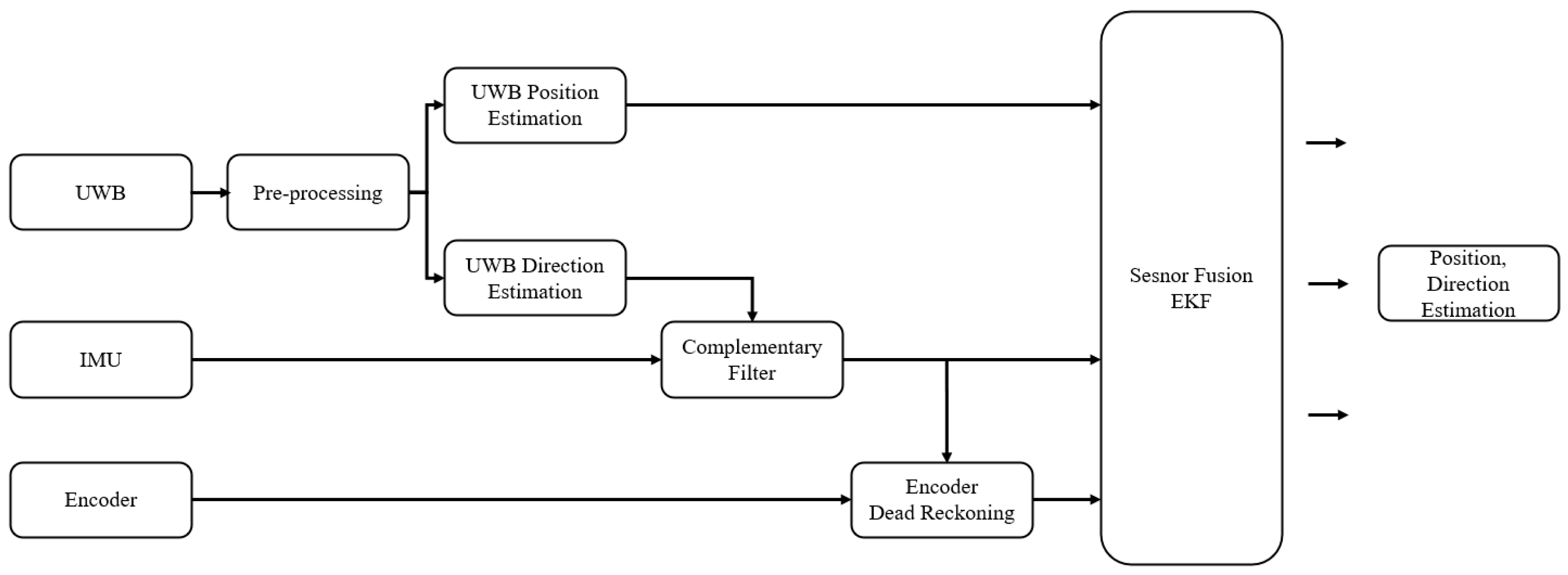
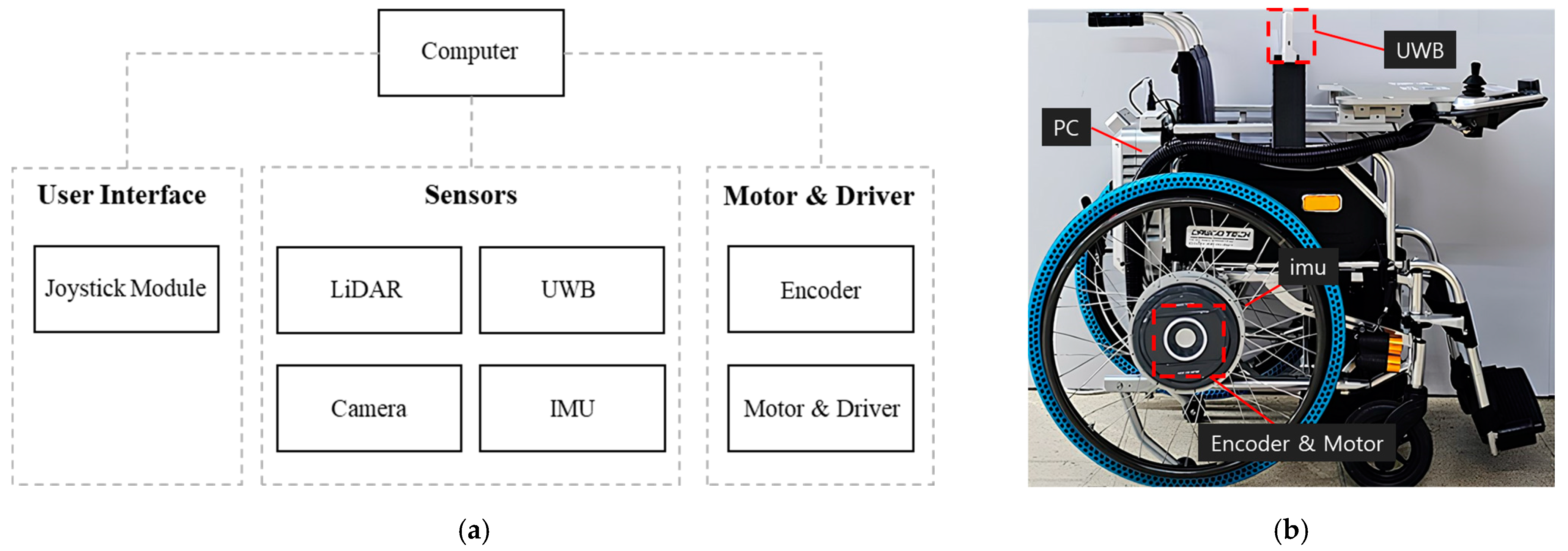
The single UWB sensor-based position and direction estimation method has difficulty correcting data distortion caused by obstacles during driving, and delays occur when noise is strongly suppressed to increase the accuracy. For this reason, it is difficult to use as a driving assistance system, and in the case of dead reckoning such as IMU/encoder, it generates data in the form of a driving record rather than initial position identification. This makes it difficult to apply it to position and direction estimation because it causes a drift error because of initial position identification and data accumulation. Therefore, this study proposes a system as shown in Figure 1 in order to perform the position and direction estimation for driving assistance technology development. Noise in the UWB sensor data is removed through the data pre-processing process proposed in this study to suppress strong noise.
The active driving assistance algorithm to the waypoint proposed in this paper requires direction and position information for active driving from the current position of the wheelchair. For this purpose, the yaw value of the IMU sensor data and the direction data from the UWB sensor are combined in the form of a complementary filter to estimate the direction information. The reason for this is that the real-time orientation information estimation of the wheelchair has an error due to the slip of the wheelchair’s encoder information, so the error can be improved by estimating the yaw value of the IMU sensor, and the drift error caused by the yaw integration process can be improved by the position-change amount calculated with the UWB.
The position information estimation can basically use the position value estimated by the UWB sensor. However, the distance error of the UWB sensor system can be improved by installing many sensor nodes, but the type proposed in this paper has an error range of 10~30 cm, and it is difficult to estimate the change according to the amount of instantaneous rotation of the wheelchair, so we propose a method to update the distance information to the waypoint by fusing the change amount of the IMU sensor and the encoder sensor attached to the wheelchair with the EKF algorithm.
Among the methods for fusing sensor data, the complementary filter-based sensor fusion, AI-based sensor data fusion method, Kalman filter, and particle filter-based sensor data fusion method are representatively used [34,35,36,37]. In the case of complementary filters, sensors are fused through mutual compensation between each data source, and they are utilized when the characteristics of each sensor are clear. AI-based sensor fusion mainly designs neural networks by learning from large amounts of data when it is difficult to define the characteristics of data collected from sensors [38]. Therefore, they are effective in deriving results through probabilistic decisions based on large databases, mainly in object recognition and estimation or inference with unclear features. However, AI-based fusion methods are computationally intensive when processing data compared to other algorithms and require a lot of data for training. The Kalman filter is a sensor fusion algorithm that fuses each sensor based on a system model and iteratively performs state prediction and measurement updates to estimate results based on real-time sensor data. Particle filters update their measurements by iterating through resampling and prediction based on probability.
Particle filters have the advantage of less computation compared to AI algorithms, but since they perform fusion based on probability, they require a larger amount of sensor data to be resampled compared to the Kalman filter algorithm. The use of particle filters compared to Kalman filters is not suitable for the use of UWB/IMU/encoder sensors in this paper. AI-based sensor fusion methods can be effective, but when the amount of data is small, the relationships among the data are distinct, such as the UWB/IMU/encoder sensor used in this paper, and the modeling is relatively easy to implement, sensor fusion techniques using complementary filters and Kalman filters do not have a large error range compared to AI-based sensor fusion methods. Considering the resources required for the design and computation of both sensor systems, this paper proposes a sensor fusion system using a complementary filter for direction information estimation and a Kalman filter for position information estimation.
Therefore, the fusion in this study was based on the Kalman filter. Since the sensor system to be fused currently has nonlinearity, it should be carried out based on algorithms such as EKF, UKF (unscented Kalman filter), and CKF (cubature Kalman filter), which are expanded Kalman filter algorithms. In this study, sensor fusion was performed through EKF, which is suitable for intelligent wheelchairs with lower computation than CKF and UKF, by evaluating new measurement data to suppress the noise included in the data and correct the result by estimating new results [39].

2.2.1. UWB-Based Object Estimation Technique

The data collected from the UWB module have high noise and may include strong outlier data due to the influence of multiple paths caused by diffraction, reflection, etc. of radio waves due to unexpected obstacles [40]. Therefore, data pre-processing is needed to remove noise and outliers for implementing precise UWB sensor-based position estimation. Noise and outliers are removed through the data pre-processing process presented in this study. Then, the position and direction angle are estimated through the position estimation and direction angle estimation algorithm considering the outdoor getting on/off space.

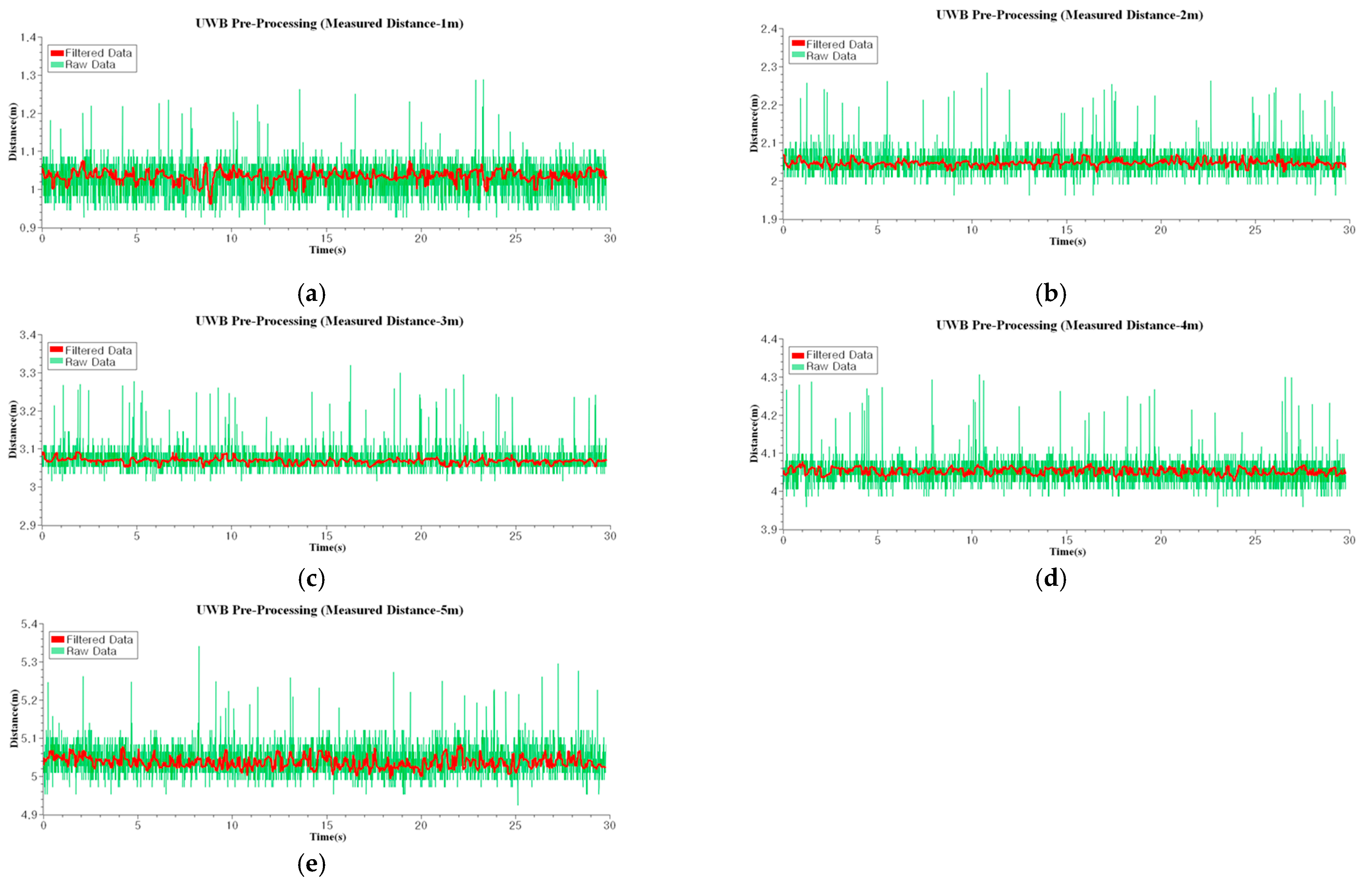
Pre-Processing of UWB Sensor Data

The data collected from the UWB sensor generally include high outliers and strong noise due to the noise generated from the multiple paths caused by diffraction and reflection of radio waves because of obstacles and the intensity of radio reception. Therefore, since the collected UWB sensor data show strong outliers and high noise, errors in the Kalman filter covariance calculation and prediction process can be added to the sensor fusion system through the Kalman filter. For this reason, pre-processing is required. Therefore, various filter theories are used to remove noise from such data, and representative methods include average filter, median filter, and exponential smoothing filter [41,42,43].
The average filter reduces noise through the principle of averaging after data collection, but it is not suitable for use in the pre-processing of the UWB sensor because it calculates the average including the outliers of the UWB sensor. The median filter collects a large number of data and uses intermediate values to remove noise. However, there is a problem that various measured values other than outliers are cancelled as intermediate values because of the nature of the median filter, even though there is a strong advantage in the outliers. In this study, since the UWB sensor was used to estimate the position of a moving wheelchair, the median filter, which may cancel the data obtained during movement, is not suitable for sensor pre-processing. In the case of the exponential smoothing filter, it is a filter that accumulates and calculates the previous value and the current value with a constant index. However, it is not strong against outliers like the previous average filter. In addition, since this is a filter that is calculated by continuously accumulating the previous values, it is affected by outliers and delays in the previous values. Therefore, it is not suitable as a pre-processing process for the UWB sensor. Figure 2 shows the data pre-processing flow chart proposed in this study, and when data are input, the data are first selected and stored based on Q b u f f e r with n sizes. Then, the stored data are copied to S b u f f e r to calculate the median value. In order to remove strong outliers and noise in S b u f f e r , data that do not have noise greater than or equal to a weight α in the median value are stored in M b u f f e r . Then, the average is calculated based on the data remaining in M b u f f e r . Therefore, since the average is derived by removing outlier values of a certain value or more after calculating the intermediate value for each data, the disadvantage of the average including outliers of the average filter can be removed and the average of the cancelled value of the median filter can be calculated. For this reason, this study proposes this pre-processing for the UWB sensor data.

UWB Positioning

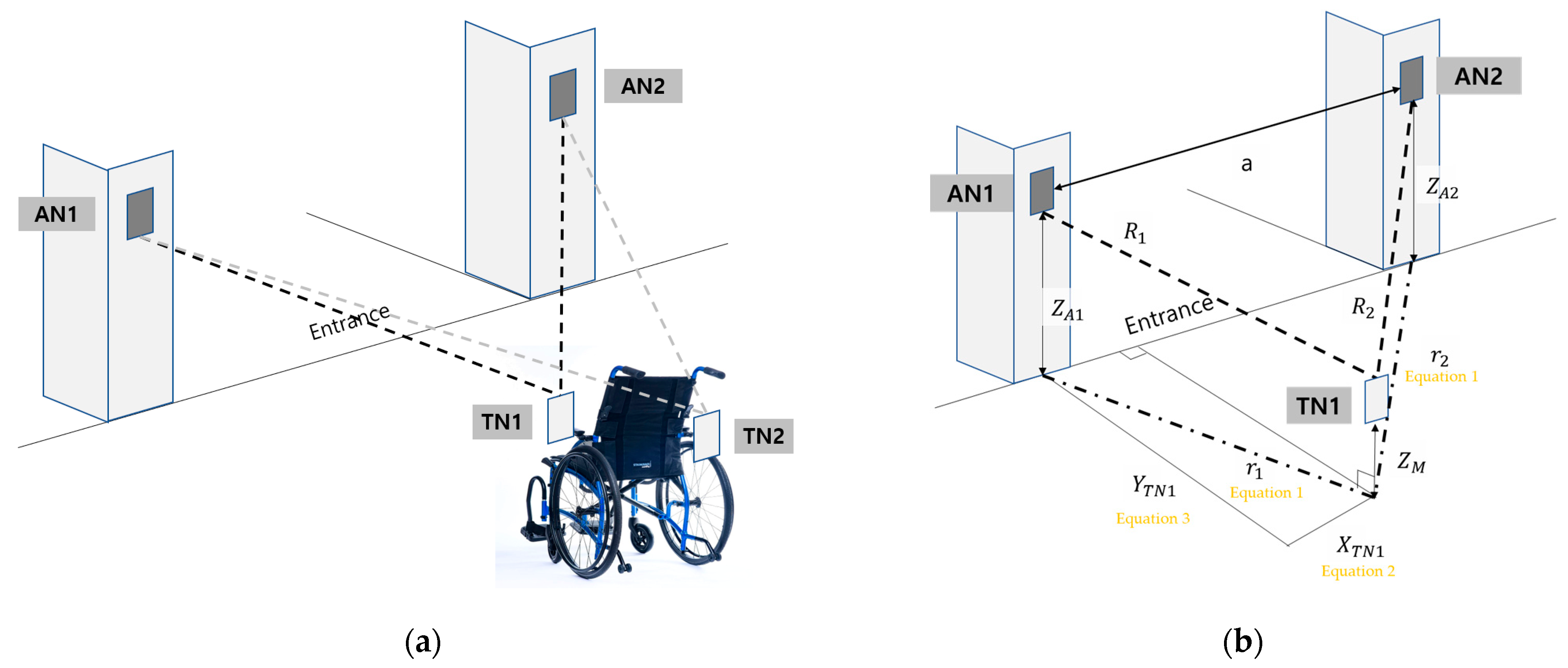
The position estimation system using the UWB sensor basically consists of a number of fixed nodes (ANs, anchor nodes) and mobile nodes (TNs, tag nodes) that identify the installation position accurately. In general, the method of estimating the position using the UWB sensor is implemented using a triangulation method, and three straight distances are required for this. However, since it is difficult to install ANs at both ends of the entrance and exit of the wheelchair getting on/off space, as proposed in this study, the position is estimated by installing two ANs at both ends of the entrance door, as shown in Figure 3. Therefore, this study proposes a position plan consisting two ANs in consideration of the anchor environment mounted at the entrance of the building under the assumption that the position of the ANs and the position of the TN mounted on the wheelchair are known.
The r j in Equation (1) is the distance on the plane and is calculated through the UWB sensor distance R j 2 , the height Z A j of AN, and the height Z M of TN. Equation (2) is the X-coordinate in the plane and Equation (3) is the Y-coordinate in the plane. The coordinates of the wheelchair are calculated based on the obtained TN positions.
r j = R j 2 ( Z A j Z M ) 2
X T N = r 1 2 r 2 2 + a 2 2 a
Y T N = r 1 2 x 2

Estimation of the UWB Direction Angle

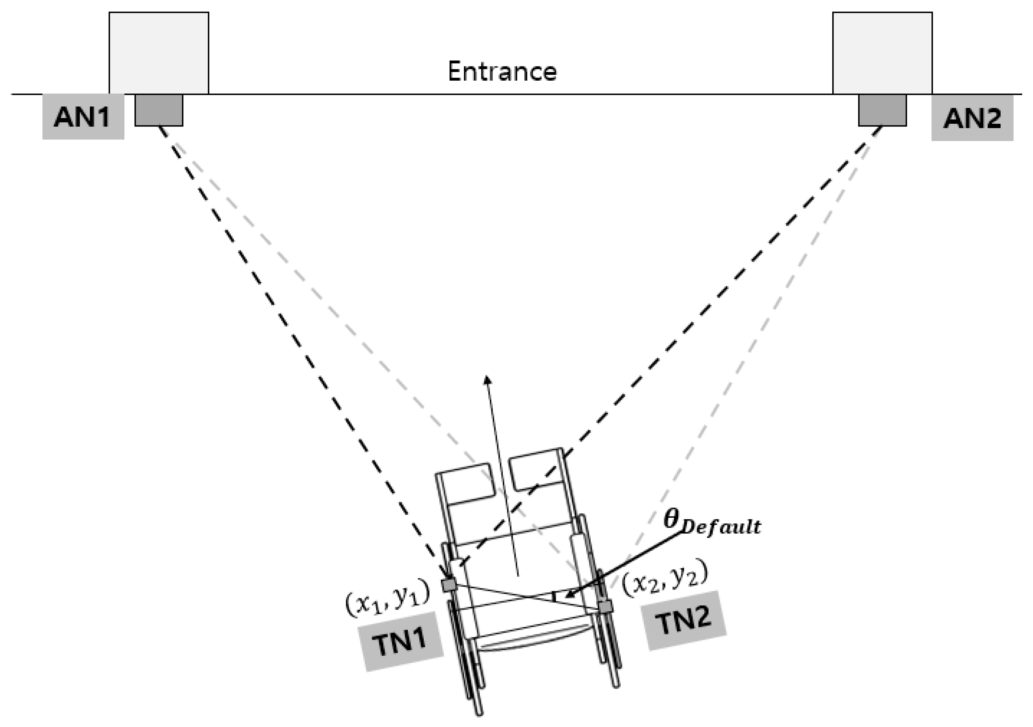
In order to estimate the direction angle, at least two TNs must exist in a wheelchair, and the direction angle of the wheelchair is estimated based on the position of the TN installed on the wheelchair. Figure 4 shows the process of estimating the direction angle based on the position of the TN measured from the two ANs mounted at both ends of the entrance.
The relative direction estimation of the wheelchair is performed through Equation (4). θ D e f a u l t is the UWB angle installed in the existing wheelchair and θ U W B is the direction angle of the wheelchair. Through this, the direction angle can be estimated from the UWB sensor.
θ U W B = A T A N 2 ( Y 2 Y 1 X 2 X 1 ) + θ D e f a u l t

2.2.2. Dead Reckoning

The position data measured from the UWB sensor show errors when measuring the amount of change in a short distance due to the reception strength of obstacles and radio waves. Therefore, in order to correct the amount of change in such a short distance, the amount of change over time is calculated by performing dead reckoning based on the IMU and encoder sensors, which have the strength of the short-range change. Based on this, this study compensates for the drift error, which is a disadvantage of dead reckoning based on IMU and encoder sensors, using the UWB sensor data. Based on this, this study proposes a method for compensating the short-range error in the UWB sensor data.

IMU Dead Reckoning

The use of the IMU sensor data proposed in this study assumes that the wheelchair moves in the 2D plane and uses only the angular velocity sensor data on the yaw axis instead of the geomagnetic sensor in consideration of the electromagnetic field generated from the motor. Equation (5) shows the calculation of the direction of the wheelchair at time t in the angle change θ G y r o ( t ) measured between time t − 1 and t from the yaw axis angular velocity of the IMU. Therefore, the amount of change in the angle over time can be calculated through the IMU.
θ G y r o ( t ) = θ G y r o ( t 1 ) + θ G y r o ( t )

Encoder Dead Reckoning

The wheelchair has a wheel structure, and mechanical dead reckoning according to the structure must be performed. Both wheels of the electric wheelchair used in this study are equipped with encoder sensors to measure the rotational speed of the wheel. Figure 5 shows the process of mechanical modeling of wheeled mobile robots.
The speed and the amount of coordinate changes of the mobile robot are calculated by Equations (6) and (7). Equation (6) calculates the speed of the robot through the velocity V R on the right wheel of the robot and V L on the left wheel. Equation (7) calculates the X-axis position change, X E N , and Y-axis position change, Y E N , through the robot direction, θ t , and the robot speed, V r o b o t . Based on this, the position change of the robot over time is calculated.
V r o b o t = V R + V L 2
X E N Y E N = c o s θ t s i n θ t s i n θ t c o s θ t V r o b o t 0 d t

2.3. Proposed Sensor Fusion Technique for Active Driving Assistance

Position estimation using a single UWB sensor results in a strong error due to the obstacles and the reception strength of radio waves. Therefore, the direction also has a strong error in estimating the direction through the position estimated based on the UWB sensor. Since this is difficult to use as a direction estimation for active driving assistance, the direction is estimated with the fusion technology based on the yaw angular velocity data and the direction data calculated from the UWB sensor and complementary filter on the IMU sensor. Based on this, this study proposes an EKF sensor-based fusion method with the UWB sensor-based position estimation data by performing dead reckoning on the encoder sensor.
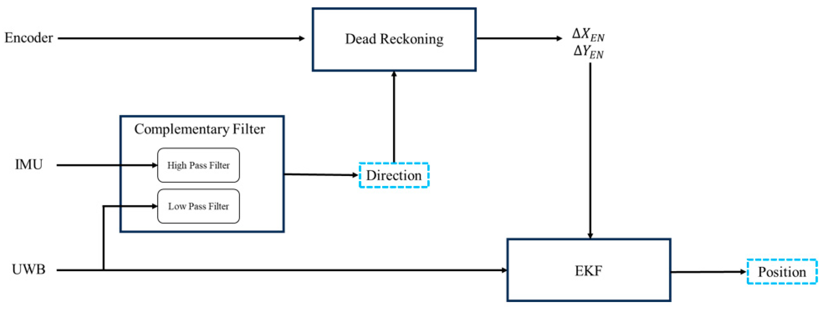
Figure 6 represents a schematic diagram of the proposed sensor fusion technique for active driving, showing the process of estimating the direction and position using the fusion of UWB/encoder/IMU sensors. The sensor fusion technique for active driving assistance proposed in this study is largely carried out in three processes. First, the direction of the wheelchair is calculated based on the complementary filter. After that, the amount of the wheelchair X-axis position change, X E N , and the amount of the Y-axis position change, Y E N , are calculated through the calculated direction and encoder sensor data. Finally, the position of the wheelchair is calculated by fusing the calculated position change and the UWB position data.
There are two problems when calculating the angle based on the angular velocity value of the IMU. First of all, since the angle calculated by accumulating the angular velocity as an absolute angle cannot be obtained at present, only the difference between the angle of the starting point and the measurement point can be calculated if the angle of the wheelchair at the starting point is not known. The second is the drift error caused by accumulating angular velocity values to measure the angle [44]. Therefore, in this study, the angle of the wheelchair calculated from the UWB sensor and the angle of the wheelchair measured from the IMU sensor are fused using Equation (4) in order to solve these two problems. The data measured from the UWB sensor include high noise, but there is no drift error because it is not a cumulative calculation. The acceleration data measured from the IMU sensor have less noise, but drift error occurs. In order to implement the fusion based on the characteristics of these two data types, this study proposes a method using a complementary filter. The complementary filter is usually used when the two data types have mutually secure frequencies, and the UWB sensor data have low-frequency noise, and the angular velocity obtained with the IMU sensor have high-frequency noise. Since each data type is fused through filters of different frequencies using the complementary filter, the UWB and IMU sensor data with different characteristics are fused and utilized. As shown in Equation (8), the UWB sensor data and IMU angular velocity sensor data can be fused. Based on the weight of the complementary filter, β , the angular velocity θ U W B measured from UWB and the angular velocity θ G y r o ( t ) of the yaw axis measured from IMU are fused to calculate the angle of the current wheelchair, θ t . Based on this, Equation (7) is implemented to calculate the amount of X E N and Y-axis position change, Y E N , of the wheelchair.
θ t = 1 β θ G y r o t × t + θ t 1 + β × θ U W B
EKF is an algorithm that calculates the covariance of sensors through past and new measurement data and estimates the results by fusing each sensor according to the system model. This is often used to calculate estimates by fusing sensor data based on data that are difficult to measure precisely due to a lot of noise from each sensor and supplementing the shortcomings of each sensor [45]. Therefore, EKF is used in this study to remove noise included in the data and estimate the result of fusing the sensors.
The sensor fusion algorithm presented in this study estimates the position and direction of the wheelchair by fusing the amount of real-time position data, X E n and Y E n , previously calculated by the encoder sensor; the direction, θ t , calculated by fusing the angle data measured from the IMU and UWB sensors using a complementary filter; and the positions X U W B and Y U W B calculated from the UWB sensor.
Equation (9) is a step of predicting the position and direction of time t in the system model A for considering a wheeled mobile robot system and calculates the predicted value x ^ t ¯ of time t based on the estimated value x ^ t 1 of time t − 1. Equation (10) is a process of obtaining P t ¯ , which is an error covariance prediction value of time t, based on the system noise Q and system model A based on the error covariance P t 1 estimated at time t − 1. Equation (11) is a process of calculating the Kalman gain K t , a coefficient that determines how much sensor measurements are to be reflected based on the measurement matrix H, sensor noise R, and error covariance P. Equation (12) is the final estimation value and calculates an estimated value by multiplying the value measured with the UWB and IMU sensors by the Kalman gain K. Equation (13) is a process of estimating and reflecting the current error covariance based on the calculated Kalman gain and prediction error covariance.
A = 1 0 d t 0 0 1 0 d t 0 0 0 0 1 0 0 1 ,     x ^ t ¯ = A x ^ t 1
Q = 0.01 0 0 0 0 0.01 0 0 0 0 0 0 10 0 0 10 ,     P t ¯ = A t P t 1 A t T + Q  
R = 10 0 0 0 0 10 0 0 0 0 0 0 0.01 0 0 0.01 ,     K t = P k ¯ H t T ( H t P k ¯ H t T + R ) 1
z = X U W B Y U W B X E N Y E N ,     x ^ t = x ^ t ¯ + K t ( z   t h ( x ^ t ¯ ) )  
P t = ( 1 K t H ) P k ¯

3. Experiments and Results

In order to verify the position and direction angle estimation system for driving assistance in a mapless environment proposed in this study, experiments for the before and after applying the UWB sensor data in the pre-processing, the direction angle estimation using a complementary filter, and the sensor fusion position estimation system were conducted.

3.1. Configuring the Experimental Environment

3.1.1. Experimental Environment

Three experimental environments were configured for quantitative verification of the position estimation algorithm for driving assistance proposed in this study. First of all, since the UWB sensor collects data containing strong outliers and noise, they require pre-processing. In order to compare the distance data before and after the application of the pre-processing algorithm proposed in this study, the experimental environment was configured as shown in Figure 7. An environment of a straight space without obstacles was created, and for performance evaluation, distance data before and after pre-processing were compared by applying one AN and TN. As shown in Figure 7, it is composed of a straight distance space without obstacles to proceed with the experiment at 1m intervals from 1 m to 5 m.
This study proposes a UWB sensor-based direction estimation technology to assist in active driving to the destination of an intelligent wheelchair. However, since the direction estimation is less accurate with only a single UWB sensor, this study proposed a sensor fusion technology based on a complementary filter for the direction data from UWB and IMU sensors. The improved UWB direction estimation technique proposed in this study is a method of fusing the direction estimation data using the UWB sensor and the IMU sensor yaw angular velocity data proposed in this study using a complementary filter. Therefore, the second experimental environment, as shown in Figure 8, was configured for quantitative evaluation of the proposed complementary filter-based sensor fusion algorithm. The direction data were collected through an intelligent wheelchair platform, and an experimental environment was constructed to compare direction estimation according to the UWB sensor position and UWB/IMU sensor data using a complementary filter. The experimental environment was configured to check the direction estimation accuracy compared to the actual position by mounting a camera at the bottom of the wheelchair through rotation at a predetermined position, as shown in Figure 8.
Finally, for active driving assistance to the destination of an intelligent wheelchair, this study proposed a UWB sensor-based position estimation technology. However, since the position estimation using a single UWB sensor is less accurate, a method of fusion based on the UWB/IMU/encoder sensors was proposed. Therefore, for the quantitative evaluation of the sensor fusion position estimation algorithm proposed in this study, an experiment was conducted through an experimental environment as shown in Figure 9. The experimental environment was configured to compare the results of the position estimation through an algorithm that suggests moving the designated path by attaching ANs to both ends of the door, just as ANs are attached to both ends of a narrow entrance door of a hospital or building. Two ANs were mounted at a height of 200 cm at 350 cm intervals, and the driving path was 200 cm wide and 300 cm long. For quantitative comparison, a camera was mounted at the bottom of the wheelchair to compare the actual position data with the position data estimated in the experiment to confirm its accuracy.

3.1.2. Experimental Platform

For the quantitative evaluation of the theoretical verification proposed in this study, as shown in Figure 10, the intelligent wheelchair used in the experiment consisted of a PC for calculation and UWB, encoder, and IMU sensors for position estimation. The DWM1000 module of Decawave was used as the UWB sensor and two modules were installed at 65 cm intervals, at a height of 96 cm and 20 cm in front of the drive shaft in the horizontal direction. The UWB module exchanges distance data with each AN every 15 Hz period. A rotary encoder module with a resolution of 3600 was used, which also transmits data to a PC at a rate of 15 Hz. The IAHRS RB-SDA-v1 of ROBOR was used as the IMU sensor with a high accuracy using its own filter, and data were collected in a 15 Hz cycle to design all data cycles from each sensor based on 15 Hz.

3.2. Verification of the UWB/IMU/Encoder Fusion Position Estimation

3.2.1. Verification of the Proposed UWB Data Pre-Processing

Since the distance information data have strong outliers and noise in the UWB sensor, data pre-processing is required, and an experiment was conducted to compare pre-processing and post-processing of the distance information data in the UWB sensor by applying the pre-processing algorithm proposed in this study. The experiment was conducted by collecting data at 15 Hz intervals for 30 s in the environment presented in Figure 7. As a result of the experiment, it was confirmed that the outlier removal weight α = 8 cm of the pre-processing algorithm and the average number of sample data n = 10 were ideal. Figure 11 shows the experimental graph, and it was verified that the noise and outliers of the data graph were reduced according to the application of pre-processing. Therefore, it was verified that the distance data were stably acquired regardless of the strong outliers and noise of the UWB sensor data.
Table 1 shows the comparison of data before and after pre-processing, and through this, the performance of the pre-processing algorithm can be confirmed. In the case of the raw data, the deviation PP (peak to peak) between the maximum and minimum values is large and the SD (standard deviation) is high, whereas in the case of the filtered data, which are the data after pre-processing, it was verified that both the deviation and standard deviation of the maximum and minimum values were smaller than that of the raw data. Therefore, it was verified that the influences of the noise and outliers were reduced through the pre-processing algorithm proposed in this study.

3.2.2. Verification of the Proposed Direction Angle Estimation Algorithm

Since the single UWB sensor-based direction angle estimation algorithm proposed in this study shows strong errors due to data distortion from obstacles and radio wave reception strength, a method of supplementing it using a complementary filter on the yaw-axis direction data of the IMU sensor was proposed. As shown in Figure 8, an experiment was conducted to measure the direction data through in-place rotation from 90° to −90°. The in-place rotation was rotated by 3° per second, and the experiment confirmed that the weight β = 0.03 in Equation (6), a complementary filter formula, was ideal, and the data were updated every 15 Hz cycle. For quantitative comparison of the experiment, the measurement was performed by mounting a camera at the bottom of the wheelchair scaffold and comparing it with the reference position drawn every 30°. The graph of the angle estimation experiment results is shown in Figure 12, and through this, it is possible to confirm that the direction angle algorithm fused with the UWB/IMU sensors is closer to the actual value after applying a complementary filter than the direction angle estimated only with the UWB sensor. Table 2 shows the comparison before and after the complementary filter is applied, and in the case of direction estimation based on a single UWB sensor, an average error of 6.18° and an error of up to 28.37° were verified, and an average error of up to 15.30° was confirmed through the UWB/IMU sensor-based fusion. It was verified that this showed an error of about 18% less than the direction estimation through only a single UWB sensor, and the maximum error decreased by 53%. It verified that the proposed complementary filter-based sensor fusion direction estimation algorithm showed less error than the single UWB sensor-based direction estimation and confirmed that the driving assistance system could be determined as a designable level because it was updated in real time.

3.2.3. Verification of the Proposed UWB/IMU/Encoder Fusion Position Estimation Algorithm

For the quantitative verification of the sensor fusion-based position estimation algorithm proposed in this study, the experiment was conducted in an experimental environment as shown in Figure 9. The experimental graph is shown in Figure 13, which compares the results of the three position estimation methods. The position data estimated only from the UWB sensor data show high noise and strong outliers, and the position estimation through the encoder has drift errors in which errors accumulate over time. It was confirmed that the fusion data estimated with the method proposed in this study are more stable than the UWB and encoder sensor-based estimation methods and do not show drift errors in which errors accumulate over time.
Table 3 shows the comparison of the reference position for each position estimation method, and the data estimated from the raw UWB have errors between 10 and 50 cm and show high variance. The data measured with the encoder show drift errors in which errors accumulate over time, confirming that the error increases over time, and in the case of the fusion data implemented by the method proposed in this study, stable position estimation and an error of 15 cm or less were verified. Therefore, it was verified that there was no problem in implementing the driving assistance system in the wheelchair getting on/off space proposed in this study. In the case of the pre-processing algorithm, it was confirmed that the outliers and noise of the UWB sensor data were removed after applying the pre-processing. In the case of the direction angle estimation through the complementary filter, it was confirmed that the direction estimation with reduced mean and maximum errors was possible compared to the value estimated only with the UWB sensor. In the case of the sensor fusion position estimation using EKF, it was confirmed that it was possible to estimate the position stably compared to the existing raw UWB sensor data, and there was no drift error, unlike the position estimated based on the encoder sensor. Therefore, the position and direction estimation system proposed in this study verified that the position estimation algorithm proposed by improving the shortcomings and accuracy of a single UWB sensor showed a level of accuracy capable of implementing an active driving assistance system.

4. Conclusions and Future Research Direction

In this study, a study of a position estimation system for developing driving assistance technology for mapless spaces such as wheelchair getting on/off spaces that are difficult for autonomous driving technology to navigate was conducted. In order to implement a high-accuracy position estimation system, this study was conducted to estimate a high-accuracy position and direction by fusing UWB/IMU/encoder sensors. As a result of fusing the data of each sensor, the low-accuracy problem of the general UWB sensor-based position estimation was corrected through the data from the IMU and encoder sensors built into the electric wheelchair, and based on this, the position and direction of 15 cm and 15.3° or less were estimated. Since the position and direction can be updated by receiving each sensor’s data in real time, it is expected that the driving assistance system can be implemented using the position estimation method proposed in this study. In order to implement a position estimation system based on a UWB sensor, which is characterized by noise and outliers, pre-processing is required to reduce the impact of noise and outliers in the sensor data. In this paper, encoder and IMU sensor-based data pre-processing is used to estimate the odometry of a wheelchair to improve the accuracy of a single UWB sensor. In addition, it is expected that the accuracy of the UWB sensor-based position estimation system proposed in this paper can be further improved through the fusion of LiDAR and camera sensors. In the future, research will be conducted to ensure the right to move by assisting the operation ability of those who have difficulties in operating wheelchairs through the process of getting on/off wheelchair vehicles and implementing a driving assistance system in the entrance.

Author Contributions

Conceptualization and methodology, E.J.; software, E.J. and S.-H.E.; validation, E.J. and S.-H.E.; formal analysis, E.J. and S.-H.E.; investigation, E.J. and E.-H.L. and S.-H.E.; data curation, E.J.; visualization, E.J.; writing—original draft preparation, E.J., S.-H.E. and E.-H.L.; writing—review and editing, E.J. and E.-H.L. All authors have read and agreed to the published version of the manuscript.

Funding

This research was supported by the MSIT (Ministry of Science and ICT), Korea, under the Grand Information Technology Research Center support program (IITP-2024-2020-0-01741) supervised by the IITP (Institute for Information & communications Technology Planning and Evaluation). This work was supported by the Korea Medical Device Development Fund grant funded by the Korea government (the Ministry of Science and ICT, the Ministry of Trade, Industry and Energy, the Ministry of Health and Welfare, the Ministry of Food and Drug Safety) (Project Number: RS-2020-KD000162). This research was supported by Culture, Sports and Tourism R&D Program through the Korea Creative Content Agency grant funded by the Ministry of Culture, Sports and Tourism in 2024 (RS-2023-00218166).

Institutional Review Board Statement

Not applicable.

Informed Consent Statement

Not applicable.

Data Availability Statement

The datasets generated during this study are available from the corresponding author on reasonable request. The data are not publicly available due to privacy.

Acknowledgments

This research was supported by the MSIT (Ministry of Science and ICT), Korea, under the Grand Information Technology Research Center support program (IITP-2024-2020-0-01741) supervised by the IITP (Institute for Information & communications Technology Planning and Evaluation). This work was supported by the Korea Medical Device Development Fund grant funded by the Korea government (the Ministry of Science and ICT, the Ministry of Trade, Industry and Energy, the Ministry of Health and Welfare, the Ministry of Food and Drug Safety) (Project Number: RS-2020-KD000162). This research was supported by Culture, Sports and Tourism R&D Program through the Korea Creative Content Agency grant funded by the Ministry of Culture, Sports and Tourism in 2024 (RS-2023-00218166).

Conflicts of Interest

The authors declare no conflicts of interest.

References

  1. The OECD. Demography—Elderly Population—OECD Data. Available online: https://data.oecd.org/pop/elderly-population.htm (accessed on 1 November 2023).
  2. World Health Organization. Global Report on Assistive Technology; Technical Report; World Health Organization: Geneva, Switzerland, 2022. [Google Scholar]
  3. Grand View Research. Wheelchair Market Size, Share & Growth Report; Technical Report; Grand View Research: San Francisco, CA, USA, 2022. [Google Scholar]
  4. Kim, D.-J.; Lee, H.-J.; Yang, Y.-A. The Status of Accidents and Management for Electronic Assistive Devices among the Handicapped. Korean J. Health Serv. Manag. 2016, 10, 223–234. [Google Scholar] [CrossRef]
  5. Mazumder, O.; Kundu, A.S.; Chattaraj, R.; Bhaumik, S. Holonomic Wheelchair Control Using EMG Signal and Joystick Interface. In Proceedings of the 2014 Recent Advances in Engineering and Computational Sciences (RAECS), Chandigarh, India, 6–8 March 2014. [Google Scholar]
  6. Ryu, H.-Y.; Kwon, J.-S.; Lim, J.-H.; Kim, A.-H.; Baek, S.-J.; Kim, J.-W. Development of an Autonomous Driving Smart Wheelchair for the Physically Weak. Appl. Sci. 2021, 12, 377. [Google Scholar] [CrossRef]
  7. Scudellari, M. Self-Driving Wheelchairs Debut in Hospitals and Airports. IEEE Spectr. 2017, 54, 14. [Google Scholar] [CrossRef]
  8. Industry ARC. Autonomous/Self Driving Wheelchair Market Report; Technical Report; Industry ARC: Hyderabad, India, 2022. [Google Scholar]
  9. Zheng, S.; Wang, J.; Rizos, C.; Ding, W.; El-Mowafy, A. Simultaneous Localization and Mapping (SLAM) for Autonomous Driving: Concept and Analysis. Remote Sens. 2023, 15, 1156. [Google Scholar] [CrossRef]
  10. Wijayathunga, L.; Rassau, A.; Chai, D. Challenges and Solutions for Autonomous Ground Robot Scene Understanding and Navigation in Unstructured Outdoor Environments: A Review. Preprints 2023, 13, 9877. [Google Scholar] [CrossRef]
  11. Clauer, D.; Fottner, J.; Rauch, E.; Prüglmeier, M. Usage of Autonomous Mobile Robots Outdoors—An Axiomatic Design Approach. Procedia CIRP 2021, 96, 242–247. [Google Scholar] [CrossRef]
  12. Gebresselassie, M. Wheelchair Users’ Perspective on Transportation Service Hailed through Uber and Lyft Apps. Transp. Res. Rec. 2023, 2677, 1164–1177. [Google Scholar] [CrossRef]
  13. Park, G.; Jang, S.; Jang, S.; Yoon, S. Design and Analysis of the Integrated Navigation System Based on INS/UWB/LiDAR Considering Tunnel Environment. J. Korean Inst. Commun. Inf. Sci. 2022, 47, 2147–2155. [Google Scholar]
  14. Lynch, L.; Newe, T.; Clifford, J.; Coleman, J.; Walsh, J.; Toal, D. Automated Ground Vehicle (AGV) and Sensor Technologies—A Review. In Proceedings of the 2018 12th International Conference on Sensing Technology (ICST), Limerick, Ireland, 4–6 December 2018. [Google Scholar]
  15. Xu, H.; Xia, J.; Yuan, Z.; Cao, P. Design and Implementation of Differential Drive AGV Based on Laser Guidance. In Proceedings of the 2019 3rd International Conference on Robotics and Automation Sciences (ICRAS), Wuhan, China, 1–3 June 2019. [Google Scholar]
  16. Hasirlioglu, S.; Riener, A.; Huber, W.; Wintersberger, P. Effects of Exhaust Gases on Laser Scanner Data Quality at Low Ambient Temperatures. In Proceedings of the 2017 IEEE Intelligent Vehicles Symposium (IV), Los Angeles, CA, USA, 11–14 June 2017. [Google Scholar]
  17. Li, Y.; Duthon, P.; Colomb, M.; Ibanez-Guzman, J. What Happens for a ToF LiDAR in Fog? IEEE Trans. Intell. Transp. Syst. 2021, 22, 6670–6681. [Google Scholar] [CrossRef]
  18. Zhang, H.; Zhang, C.; Yang, W.; Chen, C.-Y. Localization and Navigation Using QR Code for Mobile Robot in Indoor Environment. In Proceedings of the 2015 IEEE International Conference on Robotics and Biomimetics (ROBIO), Zhuhai, China, 6–9 December 2015. [Google Scholar]
  19. Cavanini, L.; Cimini, G.; Ferracuti, F.; Freddi, A.; Ippoliti, G.; Monteriu, A.; Verdini, F. A QR-Code Localization System for Mobile Robots: Application to Smart Wheelchairs. In Proceedings of the 2017 European Conference on Mobile Robots (ECMR), Paris, France, 6–8 September 2017. [Google Scholar]
  20. Andreev, P.; Aprahamian, B.; Marinov, M. QR Code’s Maximum Scanning Distance Investigation. In Proceedings of the 2019 16th Conference on Electrical Machines, Drives and Power Systems (ELMA), Varna, Bulgaria, 6–8 June 2019. [Google Scholar]
  21. Kim, J.-I.; Gang, H.-S.; Pyun, J.-Y.; Kwon, G.-R. Implementation of QR Code Recognition Technology Using Smartphone Camera for Indoor Positioning. Energies 2021, 14, 2759. [Google Scholar] [CrossRef]
  22. Liu, Y.; Fan, R.; Yu, B.; Bocus, M.J.; Liu, M.; Ni, H.; Fan, J.; Mao, S. Mobile Robot Localisation and Navigation Using LEGO NXT and Ultrasonic Sensor. In Proceedings of the 2018 IEEE International Conference on Robotics and Biomimetics (ROBIO), Kuala Lumpur, Malaysia, 12–15 December 2018. [Google Scholar]
  23. Adarsh, S.; Kaleemuddin, S.M.; Bose, D.; Ramachandran, K.I. Performance Comparison of Infrared and Ultrasonic Sensors for Obstacles of Different Materials in Vehicle/ Robot Navigation Applications. IOP Conf. Ser. Mater. Sci. Eng. 2016, 149, 012141. [Google Scholar] [CrossRef]
  24. Elsanhoury, M.; Makela, P.; Koljonen, J.; Valisuo, P.; Shamsuzzoha, A.; Mantere, T.; Elmusrati, M.; Kuusniemi, H. Precision Positioning for Smart Logistics Using Ultra-Wideband Technology-Based Indoor Navigation: A Review. IEEE Access 2022, 10, 44413–44445. [Google Scholar] [CrossRef]
  25. Wang, P.; Luo, Y. Research on WiFi Indoor Location Algorithm Based on RSSI Ranging. In Proceedings of the 2017 4th International Conference on Information Science and Control Engineering (ICISCE), Changsha, China, 21–23 July 2017. [Google Scholar]
  26. Caso, G.; Le, M.; De Nardis, L.; Di Benedetto, M.-G. Performance Comparison of WiFi and UWB Fingerprinting Indoor Positioning Systems. Technologies 2018, 6, 14. [Google Scholar] [CrossRef]
  27. Priyantha, N.B.; Chakraborty, A.; Balakrishnan, H. The Cricket Location-Support System. In Proceedings of the 6th Annual International Conference on Mobile Computing and Networking, Boston, MA, USA, 6–11 August 2000; ACM: New York, NY, USA, 2000. [Google Scholar]
  28. Jang, B.-J. Principles and Trends of UWB Positioning Technology. J. Korean Inst. Electromagn. Eng. Sci. 2022, 33, 1–11. [Google Scholar] [CrossRef]
  29. Park, J.; Cho, Y.K.; Martinez, D. A BIM and UWB Integrated Mobile Robot Navigation System for Indoor Position Tracking Applications. J. Constr. Eng. Proj. Manag. 2016, 6, 30–39. [Google Scholar] [CrossRef]
  30. Poulose, A.; Eyobu, O.S.; Kim, M.; Han, D.S. Localization Error Analysis of Indoor Positioning System Based on UWB Measurements. In Proceedings of the 2019 Eleventh International Conference on Ubiquitous and Future Networks (ICUFN), Zagreb, Croatia, 2–5 July 2019. [Google Scholar]
  31. Poulose, A.; Emersic, Z.; Steven Eyobu, O.; Seog Han, D. An Accurate Indoor User Position Estimator for Multiple Anchor UWB Localization. In Proceedings of the 2020 International Conference on Information and Communication Technology Convergence (ICTC), Jeju Island, Republic of Korea, 21–23 October 2020. [Google Scholar]
  32. Tian, D.; Xiang, Q. Research on Indoor Positioning System Based on UWB Technology. In Proceedings of the 2020 IEEE 5th Information Technology and Mechatronics Engineering Conference (ITOEC), Chongqing, China, 12–14 June 2020. [Google Scholar]
  33. Dai, H.; Hu, C.; Su, S.; Lin, M.; Song, S. Geomagnetic Compensation for the Rotating of Magnetometer Array during Magnetic Tracking. IEEE Trans. Instrum. Meas. 2019, 68, 3379–3386. [Google Scholar] [CrossRef]
  34. Fayyad, J.; Jaradat, M.A.; Gruyer, D.; Najjaran, H. Deep Learning Sensor Fusion for Autonomous Vehicle Perception and Localization: A Review. Sensors 2020, 20, 4220. [Google Scholar] [CrossRef]
  35. Karunarathne, M.S.; Ekanayake, S.W.; Pathirana, P.N. An Adaptive Complementary Filter for Inertial Sensor Based Data Fusion to Track Upper Body Motion. In Proceedings of the 7th International Conference on Information and Automation for Sustainability, Colombo, Sri Lanka, 22–24 December 2014. [Google Scholar]
  36. Chen, Z.; Zou, H.; Jiang, H.; Zhu, Q.; Soh, Y.C.; Xie, L. Fusion of WiFi, Smartphone Sensors and Landmarks Using the Kalman Filter for Indoor Localization. Sensors 2015, 15, 715–732. [Google Scholar] [CrossRef]
  37. Cappello, F.; Sabatini, R.; Ramasamy, S.; Marino, M. Particle Filter Based Multi-Sensor Data Fusion Techniques for RPAS Navigation and Guidance. In Proceedings of the 2015 IEEE Metrology for Aerospace (MetroAeroSpace), Benevento, Italy, 4–5 June 2015. [Google Scholar]
  38. Marsh, B.; Sadka, A.H.; Bahai, H. A Critical Review of Deep Learning-Based Multi-Sensor Fusion Techniques. Sensors 2022, 22, 9364. [Google Scholar] [CrossRef]
  39. Mallick, M.; Tian, X.; Liu, J. Evaluation of Measurement Converted KF, EKF, UKF, CKF, and PF in GMTI Filtering. In Proceedings of the 2021 International Conference on Control, Automation and Information Sciences (ICCAIS), Xi’an, China, 14–17 October 2021. [Google Scholar]
  40. Wang, T.; Chen, X.; Ge, N.; Pei, Y. Error Analysis and Experimental Study on Indoor UWB TDoA Localization with Reference Tag. In Proceedings of the 2013 19th Asia-Pacific Conference on Communications (APCC), Bali, Indonesia, 29–31 August 2013. [Google Scholar]
  41. Juneja, M.; Sandhu, P.S. Design and Development of an Improved Adaptive Median Filtering Method for Impulse Noise Detection. Int. J. Comput. Electr. Eng. 2009, 1, 627–630. [Google Scholar] [CrossRef]
  42. Lee, J.-Y. The Motion Artifact Reduction Using Periodic Moving Average Filter. J. Korea Soc. Comput. Inf. 2012, 17, 75–82. [Google Scholar]
  43. Yang, H.-F.; Dillon, T.S.; Chang, E.; Phoebe Chen, Y.-P. Optimized Configuration of Exponential Smoothing and Extreme Learning Machine for Traffic Flow Forecasting. IEEE Trans. Industr. Inform. 2019, 15, 23–34. [Google Scholar] [CrossRef]
  44. Gao, W.; Cao, B.; Ben, Y.; Xu, B. Analysis of Gyro’s Slope Drift Affecting Inertial Navigation System Error. In Proceedings of the 2009 International Conference on Mechatronics and Automation, Changchun, China, 9–12 August 2009. [Google Scholar]
  45. Huang, Z.; Fang, Y.; Xu, J. SOC Estimation of Li-ION Battery Based on Improved EKF Algorithm. Int. J. Automot. Technol. 2021, 22, 335–340. [Google Scholar] [CrossRef]
Figure 1. System diagram proposed in this study.
Applsci 14 00620 g001
Figure 2. Data pre-processing flow chart for removing UWB sensor noise proposed in this study.
Applsci 14 00620 g002
Figure 3. UWB-based wheelchair position estimation. (a) Wheelchair positioning schematic diagram; (b) UWB sensor TN position estimation.
Applsci 14 00620 g003
Figure 4. UWB-based wheelchair direction estimation.
Applsci 14 00620 g004
Figure 5. Dead reckoning in a wheeled mobile robot.
Applsci 14 00620 g005
Figure 6. Schematic diagram of the proposed sensor fusion for active driving assistance.
Applsci 14 00620 g006
Figure 7. Experimental environment for comparison before and after UWB data pre-processing. (a) Distance measurement experimental schematic plot; (b) Distance measuring experimental environment.
Applsci 14 00620 g007
Figure 8. Direction angle measurement data collection environment. (a) Angle measurement experimental schematic plot; (b) angle measurement experimental environment.
Applsci 14 00620 g008
Figure 9. Position estimation experimental environment. (a) Overall experimental environment for position estimation experiment; (b) experimental environment (200 cm by 300 cm) for position estimation experiment.
Applsci 14 00620 g009
Figure 10. Wheelchair platform and structural diagram used in this experiment. (a) Intelligent wheelchair configuration chart; (b) intelligent wheelchair.
Applsci 14 00620 g010
Figure 11. Comparison data before and after UWB data pre-processing. (a) 1 m distance measurement graph; (b) 2 m distance measurement graph; (c) 3 m distance measurement graph; (d) 4 m distance measurement graph; (e) 5 m distance measurement graph.
Applsci 14 00620 g011
Figure 12. Angle estimation experimental graphs.
Applsci 14 00620 g012
Figure 13. Position estimation experimental graphs.
Applsci 14 00620 g013
Table 1. Comparison of data before and after pre-processing.
Raw DataFiltered Data
MAXMINPPSDMAXMINPPSD
1 m1.280.900.380.0441.070.960.110.015
2 m2.281.960.320.0322.072.020.040.007
3 m3.313.010.300.0293.093.040.040.006
4 m4.303.950.340.0334.074.020.050.008
5 m5.3404.920.410.0415.084.990.080.015
Table 2. Angle estimation experimental error.
RawFusion
Maximum Error28.3715.30
Average Error6.185.09
Table 3. Position estimation experiment results.
ReferenceRaw UWBEncoderFusion
(0, 0)(0, 0)(0, 0)(0, 0)
(0, 150)(11, 154)(14, 166)(−8, 155)
(0, 300)(1, 291)(51, 325)(−12, 296)
(100, 300)(112, 280)(136, 298)(103, 295)
(200, 300)(199, 271)(253, 261)(207, 296)
(200, 150)(193, 156)(189, 110)(205, 147)
(200, 0)(189, 22)(144, −24)(200, 12)
(100, 0)(103, 18)(41, 10)(99, 7)
Disclaimer/Publisher’s Note: The statements, opinions and data contained in all publications are solely those of the individual author(s) and contributor(s) and not of MDPI and/or the editor(s). MDPI and/or the editor(s) disclaim responsibility for any injury to people or property resulting from any ideas, methods, instructions or products referred to in the content.

