1. Introduction
As the integration of new energy sources into power systems grows, challenges concerning electricity equilibrium, grid management, and safety protocols intensify. Advancements in energy storage technologies offer fresh approaches to mitigating the variability inherent in renewable energy outputs. Among these, pumped storage stands out as the most established, cost-effective, and environmentally friendly solution [
1]. It offers capabilities including peak trimming, frequency adjustment, and emergency support, serving a crucial role in power systems. Variable-speed pumped storage units (VSPSUs) are extensively researched for their efficiency, operational flexibility, and swift responsiveness [
2,
3,
4]. The VSPSU is categorized into two types: doubly fed and full-sized. Relative to doubly fed units, the full-size converter variable speed pumped storage unit (FSC-VSPSU) provides superior speed control and enhanced capability to handle fault disturbances [
5]. With the reduction of full power device costs, FSC-VSPSU will have broader development prospects in small and medium-sized capacity applications [
6,
7].
Current research on the FSC-VSPSU has extensively focused on simulation modeling, control strategies, and applications to enhance grid stability and efficiency. Significant work includes developing simulation models for these units to study their behavior under various operational conditions [
8,
9,
10]. Researchers have also explored advanced control strategies such as virtual inertia and oscillation suppression to improve dynamic responses and stability in power systems connected with FSC-VSPSUs [
11]. Furthermore, methods have been proposed to utilize FSC-VSPSU for smoothing power fluctuations [
12]. However, these studies predominantly address the performance of pumped storage under non-fault conditions. The characteristics and control strategies under power grid fault conditions are not covered. The research on the low voltage ride-through (LVRT) strategy of FSC-VSPSU only focuses on the power, voltage, and current changes caused by voltage drop without proposing specific solutions [
13]. There have been no reports of the high-voltage fault ride-through (HVRT) strategy of the FSC-VSPSU. Therefore, there is a notable gap in addressing the performance of FSC-VSPSU under fault conditions, particularly the strategies required for effective fault ride-through—a critical aspect for operational resilience.
Similarly, many scholars have explored fault ride-through strategies for high-voltage DC systems affected by AC faults. These solutions also fall into two categories: enhancing control strategies and incorporating additional power electronic equipment [
14]. Enhancing control strategies often involves adjusting converter control parameters or switching control methods to modulate power output during faults to ensure the high-voltage DC system’s stability [
15,
16]. Moreover, additional power electronic devices such as flywheel energy storage systems, supercapacitor energy storage devices, or fault current limiters can be used to absorb the unbalanced power during the fault and thus achieve fault ride-through [
17,
18,
19]. The FSC-VSPSU also incorporates a back-to-back converter similar to those used in HVDC systems. However, transferring these strategies to FSC-VSPSU systems is not advisable. This is primarily because the distinct application contexts lead to different fault characteristics, and such strategies do not take into account the specific prime mover characteristics.
Nowadays, there is a large amount of literature on fault ride-through strategies for direct-drive wind turbines with similar structures. These fault ride-through strategies are divided into two main categories, one by adding additional equipment and the other by improving the control strategy. A dynamic braking resistor can be connected in parallel on the DC side to dissipate unbalanced power and achieve LVRT. Similarly, energy storage devices such as supercapacitors can absorb the unbalanced power during voltage dips and release power after grid voltage is restored, ensuring the unit does not operate off-grid [
20,
21]. A coordination control strategy for the rotor side converter (RSC) and grid side converter (GSC) has been proposed in [
22,
23,
24], which regulates the DC bus voltage during grid faults and improves the LVRT capacity of permanent magnet wind turbines. The unbalanced power can also be stored by changing the rotor speed to stabilize the DC voltage and keep output power balanced. However, it may cause wind turbine overspeed, which affects the safe and stable operation of units [
25]. In [
26], a control strategy for GSC is proposed to avoid overmodulation and DC line overvoltage, thereby achieving HVRT. In [
27,
28], a super capacitor has been proposed to stabilize DC line voltage and enhance HVRT capability. In [
29], a control method is presented that incorporates a parallel GSC alongside the FSC to absorb the capacitive reactive current from the power grid, thus lowering the grid voltage. All the above literature is related to the study of fault ride-through strategies for direct-drive wind turbines.
Due to differences in the inherent characteristics of the units, fault ride-through requirements, and control strategies, the above fault ride-through strategies may not be applicable to the FSC-VSPSU. Compared to wind turbines, the working power of the FSC-VSPSU can be generated by grid requirements and does not require constant operation at rated power. Additionally, the water turbine is affected by a water hammer and is a nonlinear minimum phase system. The water turbines have larger power, faster speed, greater rotational energy storage capacity, and a wider range of speed operation. Moreover, the power flow of the FSC-VSPSU is bidirectional, which is different from the unidirectional flow of the grid-connected wind turbine systems. Under pumping conditions, FSC-VPSU has the ability to quickly generate load regulation, thus requiring a certain degree of fault ride-through capability. The FSC-VSPSU often operates complementary to new energy sources to support the operation of the power grid and new energy sources. Therefore, the unique operational dynamics and requirements of FSC-VSPSUs necessitate fault ride-through strategies that differ from existing methods tailored for wind turbines.
To fill the gap, this paper uniquely contributes to the field by proposing comprehensive fault ride-through strategies tailored specifically for the FSC-VSPSU. The key contributions of this research are outlined as follows:
- (1)
The operating characteristics of the FSC-VSPSU during low and high voltage conditions in power systems are studied. Power imbalance or overmodulation of the converter are dominant factors causing DC overvoltage.
- (2)
The fault ride-through requirements of the FSC-VSPSU are proposed. To maximize support for renewable energy and the power grid, a stronger fault ride-through capability is required compared to that of wind turbines.
- (3)
A combined control strategy for fault ride-through of the FSC-VSPSU is proposed. This strategy includes fast power droop, reactive power compensation, rotor kinetic energy regulation, power reversal, low-power protection, a crowbar circuit, etc. Unique fault ride-through combination strategies are applied under various operating conditions and control modes.
The remaining part of this paper is structured as follows:
Section 2 presents the structure and control strategy of the FSC-VSPSU. Subsequently,
Section 3 analyzes the low voltage and high voltage fault characteristics of the FSC-VSPU under different operating conditions.
Section 4 proposes the LVRT and HVRT strategies under different operating conditions. The effectiveness of the fault ride-through strategies is verified through simulation analysis in
Section 5.
Section 6 draws research conclusions.
3. Analysis of Fault Ride-Through Characteristics
3.1. LVRT Characteristics
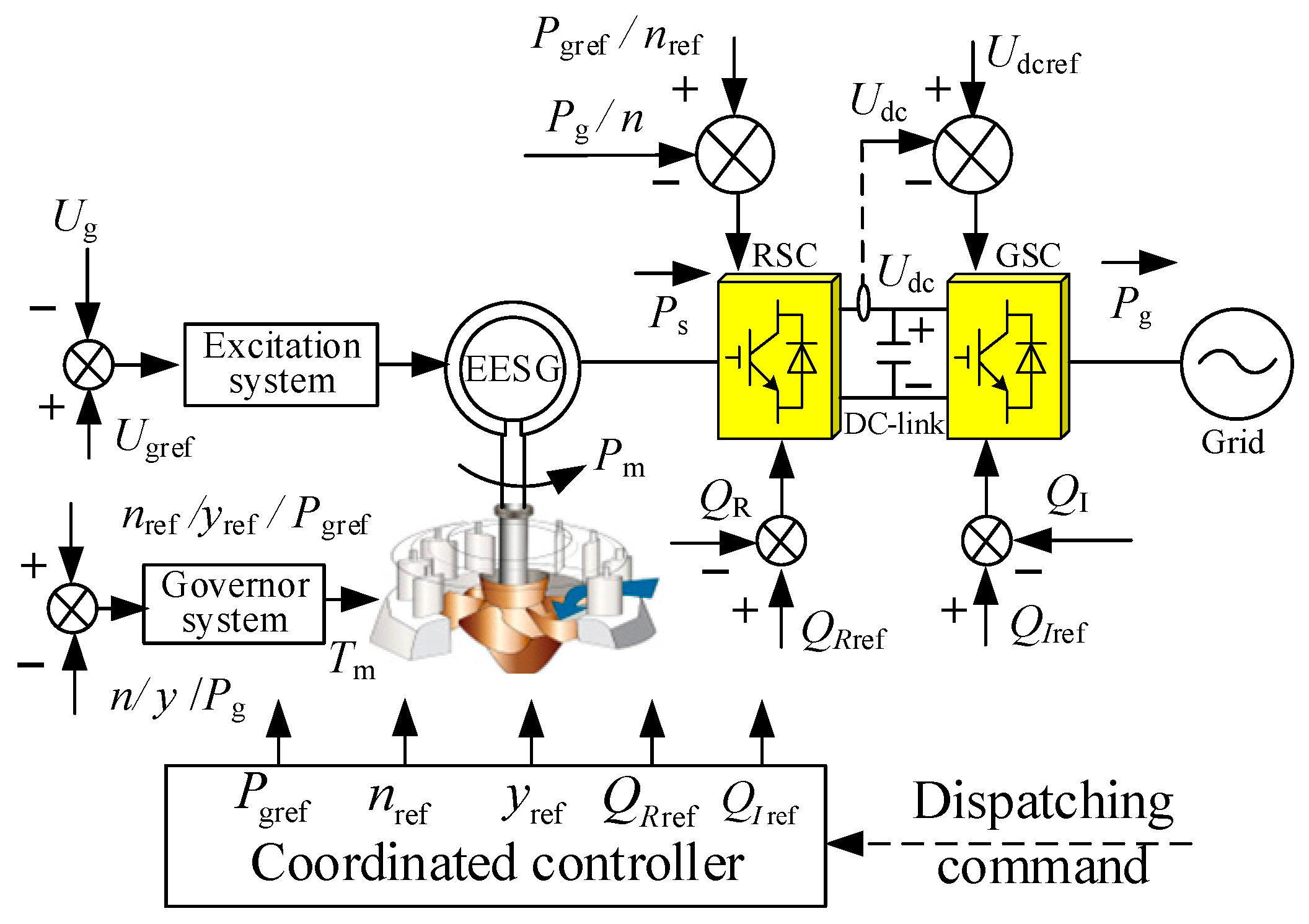
As shown in
Figure 1,
Pm,
Ps, and
Pg represent the turbine mechanical power, the active power delivered to the RSC, and the active power delivered by the GSC to the grid, respectively. When the FSC-VSPSU operates under the power generation condition normally, the power on both sides of the converter is balanced, i.e.,
Pm =
Ps =
Pg. Therefore, the DC bus voltage value
Udc satisfies Equation (3).
The unbalanced power ΔP is approximately zero under normal operating conditions, and the DC bus voltage Udc remains constant. Once the system voltage drops, it is considered that the converter has a certain current limit value, and the current will not suddenly change. When the current reaches the current limit value, the voltage at the grid connection point decreases. Consequently, the active power Pg on the grid side decreases, while the active power Ps of the power transmitted by the generator changes less. Therefore, the unbalanced power ΔP will be greater than zero, and the DC bus voltage will increase.
Assuming that the FSC-VSPSU operates at rated power, at this time the grid voltage and the active current are
egd and
igd, respectively. The grid voltage drops to
egd1, and the active current drops to
igd1. Without considering the current limiting of the inverter, the GSC is controlled by zero reactive power. According to the principle of power balance, the grid-side power
Pg1 during the fault period satisfies Equation (4).
Assuming that the minimum voltage during the fault period and the maximum overcurrent capacity of the converter are
ku times the rated voltage and
ki times the rated current, respectively, and it is also assumed that the DC voltage does not suddenly change at the moment of the fault. After the converter current limitation is activated, the DC power satisfies Equation (5).
Consequently, during the low voltage period, the DC voltage satisfies Equation (6):
where
Udc0 represents the rated DC voltage during normal operation. Therefore, the deeper the system voltage drop, the smaller the overcurrent capacity of GSC and the higher the DC overvoltage. By neglecting the power loss of the water pump turbine unit, the generator rotor speed
ω satisfies Equation (7):
where
JT is the rotational inertia of the rotor. Due to the regulation time scale of the governor system being in the second level and the hysteresis effect of water, the mechanical power
Pm remains basically unchanged for a short period after a disturbance occurs. However, the electromagnetic power output
Ps is blocked. Therefore, during the low-voltage period of the system, the unit speed will fluctuate.
When the FSC-VSPSU operates under pumping conditions, referring to the analysis of power generation conditions, the DC voltage under pumping conditions satisfies Equation (8).
Therefore, the deeper the system voltage drop, the smaller the overcurrent capacity of GSC, and the lower the DC voltage. According to this, it can be inferred that the voltage on the DC capacitor will significantly decrease. Although there is no risk of overvoltage, if the DC voltage is too low, the converter will deviate from the stable operating point, potentially leading to unstable operation. Under the pumping conditions, the rotor speed of the motor satisfies Equation (9).
During the low-voltage period, the converter is unable to smoothly transmit power from the grid to the motor in a short period, and the electromagnetic power PS on the machine side will be significantly reduced. The mechanical power Pm remains basically unchanged, which will lead to a spontaneous decrease in frequency or speed of the unit. According to Equation (2), it is known that a significant decrease in unit frequency or speed will significantly decrease the flow rate and water head. If the frequency or speed is too low, the unit will seriously deviate from the optimal pumping point, and its operation efficiency will be reduced. Additionally, if the water flow surges in the diversion pipeline for a long time, it will pose a safety risk on the pipeline or even force the unit to shut down.
3.2. HVRT Characteristics
Based on the FSC, the EESG and the power grid are completely isolated. When grid voltage rises, the GSC is the first one to be affected. The generator/motor passively responds to the influence of the RSC perturbation, and the GSC is capacitively coupled to the RSC through the DC capacitor. Therefore, maintaining the stability of the DC bus voltage is essential for uninterrupted operation when the system voltage rises.
The current relationship of the GSC in the
dq rotating coordinate system can be expressed as Equation (10):
where
ed and
eq are the d-axis and q-axis components of the grid voltage;
ugd and
ugq are the d-axis and q-axis components of the output voltage on the AC side of the GSC;
id and
iq are the d-axis and q-axis components of the input current of the GSC;
Rg and
Lg are the incoming resistance and filtering inductance of the GSC, respectively;
ω is the grid angular frequency.
When the voltage vector of the power grid is oriented along the d-axis,
ed =
E,
eq = 0.
id and
iq respectively represent the active and reactive components of the current, where
E is the peak phase voltage of the power grid. During normal conditions, both
id and
iq are DC components, and the differential term is zero. According to (10), the control equation of the GSC during normal conditions can be obtained as shown in Equation (11).
When the power factor angle of the GSC operates at a certain value, there is a certain constraint relationship between the maximum output voltage of the GSC and the DC voltage. Based on voltage modulation theory, the modulation ratio
m should satisfy Equation (12).
Therefore, the DC bus voltage
Udc satisfies Equation (13).
According to Equations (12) and (13), a rise in grid voltage not only raises the DC side voltage but may also lead to overmodulation in the GSC, which makes the GSC lose control and a reverse flow. The DC bus voltage of the FSC-VSPSU must increase proportionally with the GSC output voltage so as to prevent overmodulation and prevent the grid-side converter from losing control. Additionally, it is also necessary to avoid excessive DC bus voltage that could cause the pumped storage unit to disconnect from the grid.
Under the power generation conditions, if the voltage at the receiving end grid suddenly rises, the grid-side power cannot be properly dispatched, causing power flow into the FSC from the machine side. According to Equation (3), this will cause the DC bus voltage to rise, which can directly threaten the normal operation of the unit. Similarly, under pumping conditions, an increase in grid voltage can also lead to DC overvoltage.
4. Fault Ride-Through Control Strategies
Based on previous analysis, a decrease or increase in grid voltage may lead to DC overvoltage, low voltage, and overmodulation of the converter, jeopardizing the unit’s operation and potentially causing tripping. This could endanger the unit’s secure functioning and potentially result in trips. Therefore, this section proposes the fault ride-through strategies.
4.1. Fault Ride-Through Requirements
At present, research on fault ride-through requirements is mainly focused on wind turbines. However, there are no relevant requirements for the FSC-VSPSU. The complementary operation of pumped storage and renewable energy is an effective way to address issues such as power fluctuations. In order to maximize support for renewable energy, it is required that the fault ride-through ability of the FSC-VSPSU is superior to that of renewable energy.
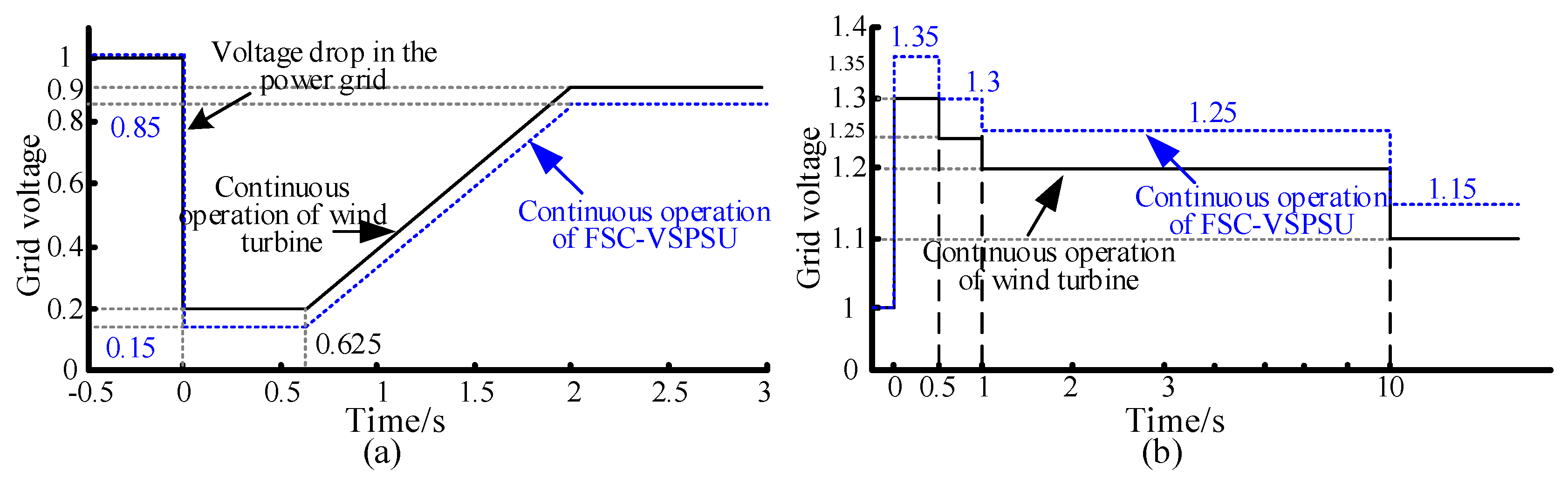
Figure 6 compares the LVRT and HVRT characteristics of the proposed FSC-VSPSU with those of wind turbines. Specifically,
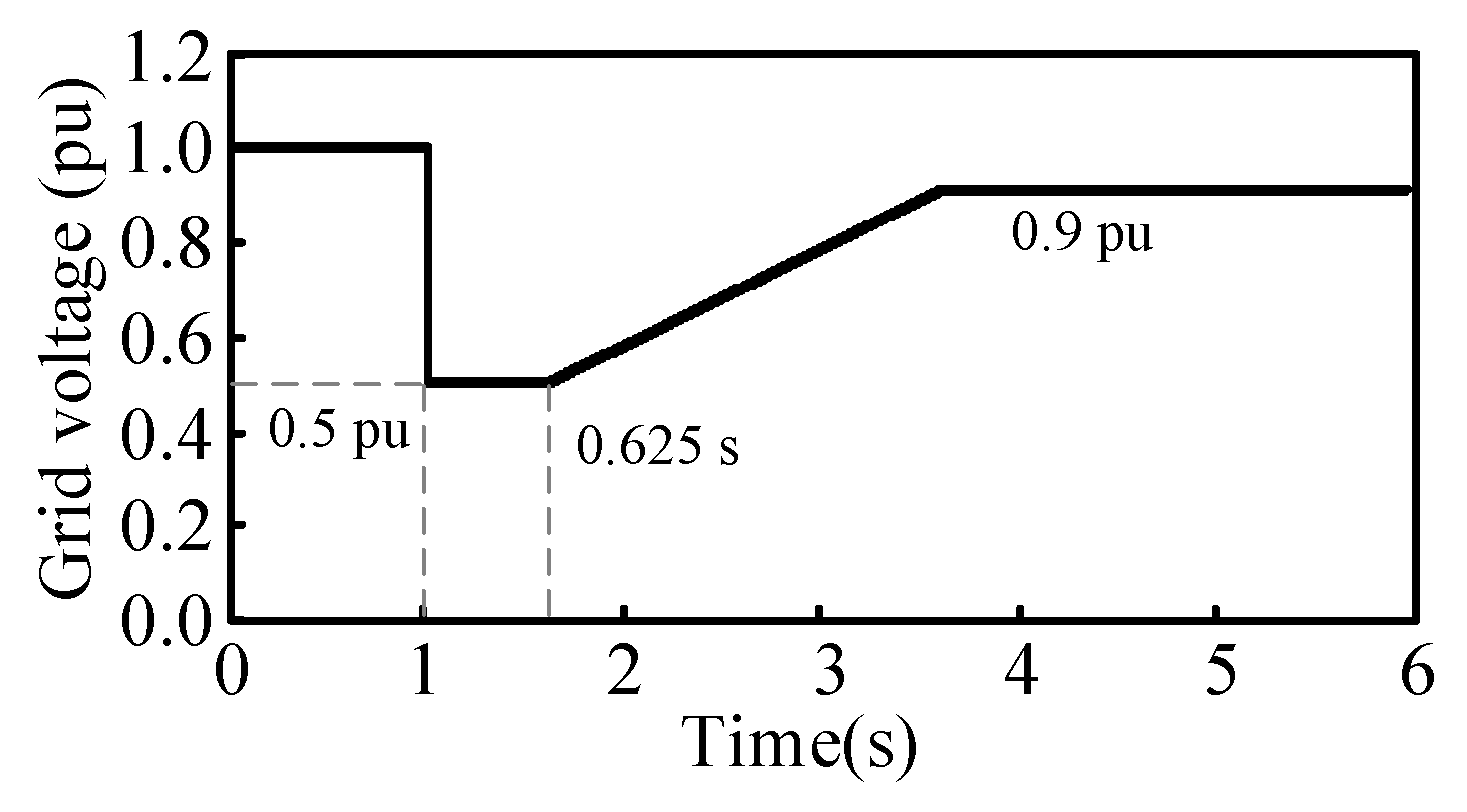
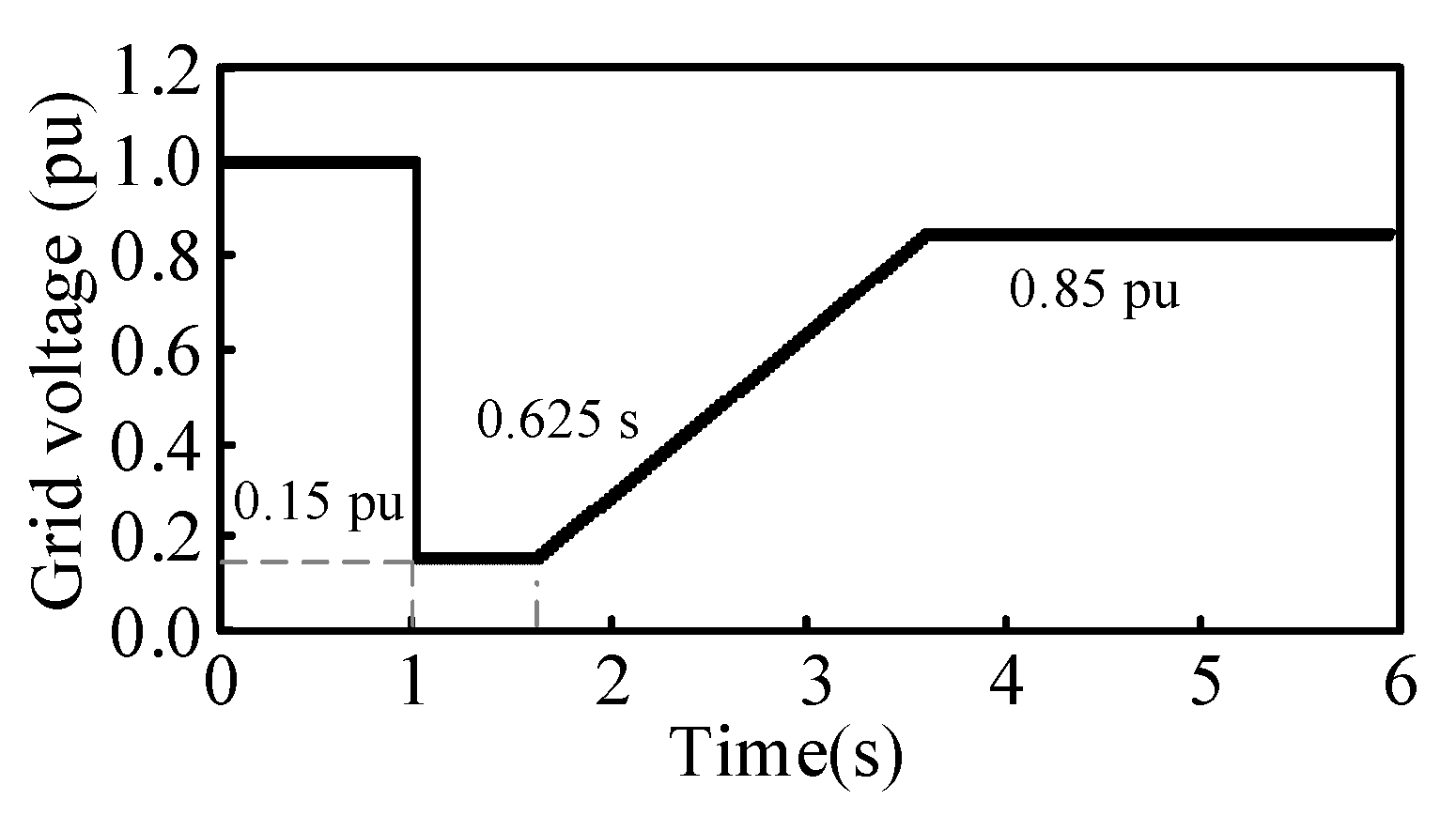
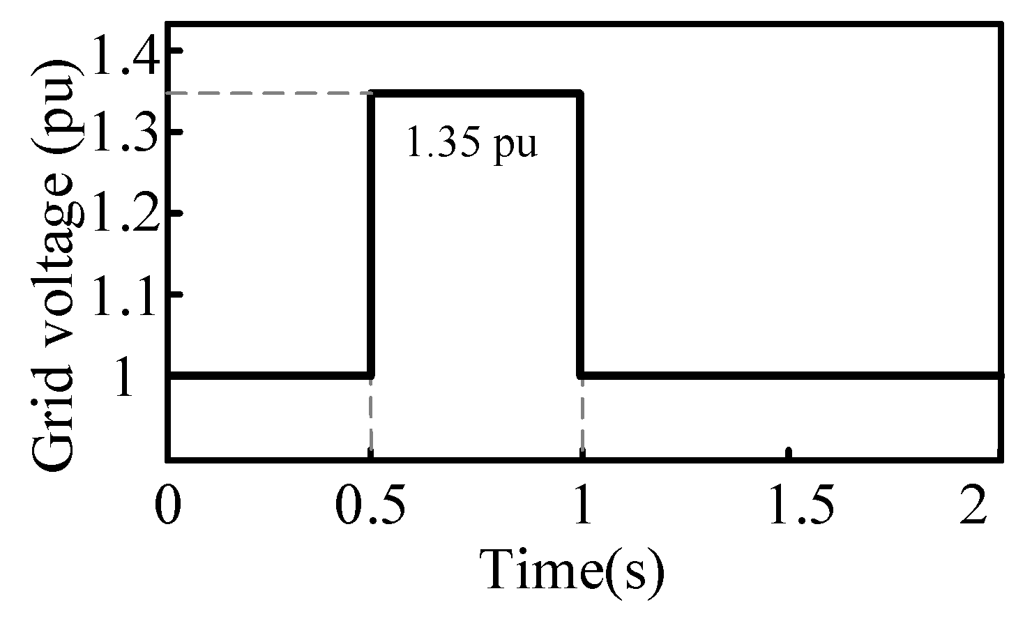
Figure 6a illustrates the LVRT characteristics. The FSC-VSPSU should sustain operation for 625 ms at a voltage drop to 15% of the rated voltage at the grid connection point and continue without disconnection if grid voltage recovers to 85% of the rated voltage within 2 s.
Figure 6b illustrates the HVRT characteristics of the FSC-VSPSU. At voltage increases to 130–135% of the rated voltage at the grid connection point, it should continue operating for 1 s without grid disconnection. At 125%, it should maintain operation for 9 s. At 115% of the rated voltage, the FSC-VSPSU can operate indefinitely.
4.2. LVRT Strategy in Generation Condition
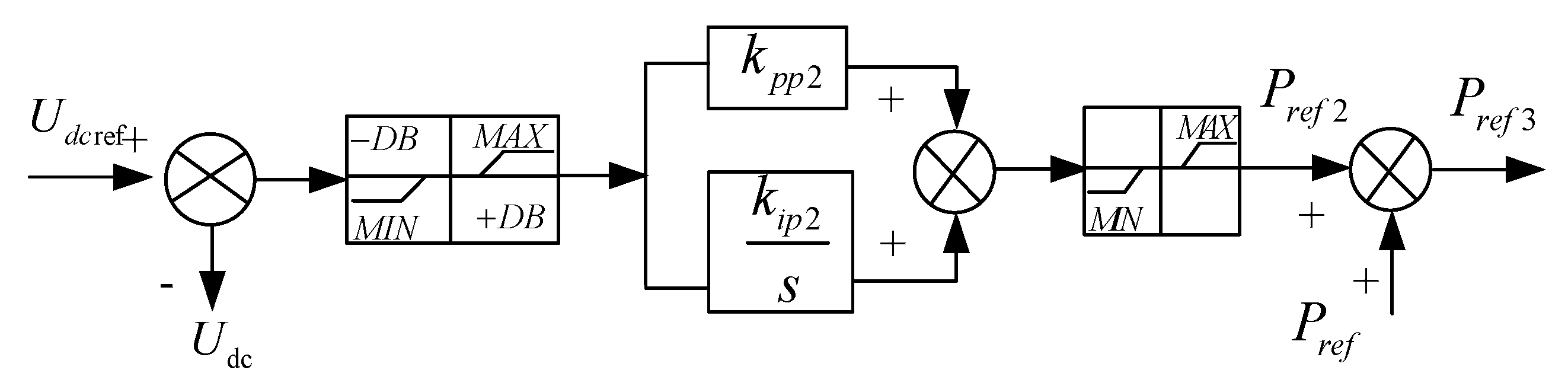
Under power generation conditions in fast power mode, the RSC rapidly adjusts real power, often within hundreds of milliseconds, for swift power reduction, as shown in
Figure 7. The DC voltage deviation undergoes processing through a dead zone and limiting link, adjusted by the PI controller to output the necessary power regulation, which then integrates into the power reference to form a new regulation command. Moreover, the GSC provides reactive power during grid voltage drops [
24]. To protect against DC overvoltage in engineering practice, a crowbar circuit is often necessary [
22].
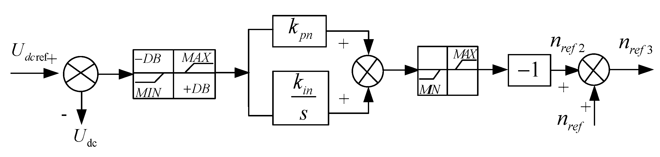
However, in fast speed mode, the aforementioned strategies become inapplicable for the FSC-VSPSU. The speed of power regulation is slower in this mode as it is governed by the turbine governor, not allowing for rapid power reduction. Here, the unit speed is managed by the RSC and can be adjusted within milliseconds. Given the greater inertia of FSC-VSPSU compared to wind turbines, employing rotor energy storage is particularly effective at absorbing excess turbine-side power, thus mitigating DC overvoltage.
When the generator speed increases from
n0 to
n1, the rotor stores part of the kinetic energy, which can be expressed as:
where
Ek0 = 1/2
TJn02.
Ek0 is the initial kinetic energy, and
Ek1 is the kinetic energy corresponding to the rotational speed
n1. Δ
Ek is the decreased kinetic energy.
TJ is the rotational inertia.
Figure 8 shows the rotor energy storage control strategy. The DC voltage deviation passes through a dead zone and limiting link, and after being adjusted and limited by the PI controller, the corresponding speed adjustment amount for rotor kinetic energy adjustment is output. This is superimposed on the optimal speed reference to form a new speed adjustment instruction.
Due to the limited rotational inertia and the finite capability to increase speed, the effectiveness of reducing input power through rotor energy storage is constrained. Directly reducing the output power of the prime mover would be more effective; however, water has a significant inertia with a time constant typically between 2–5 s. The mechanical governor also adjusts slowly, fully opening the guide vanes in about 12–15 s, making rapid power reduction challenging. However, the water hammer effect offers a reverse regulation characteristic of power, which can be leveraged to moderately reduce mechanical power. This approach is termed the power anti-regulation strategy (PARS).
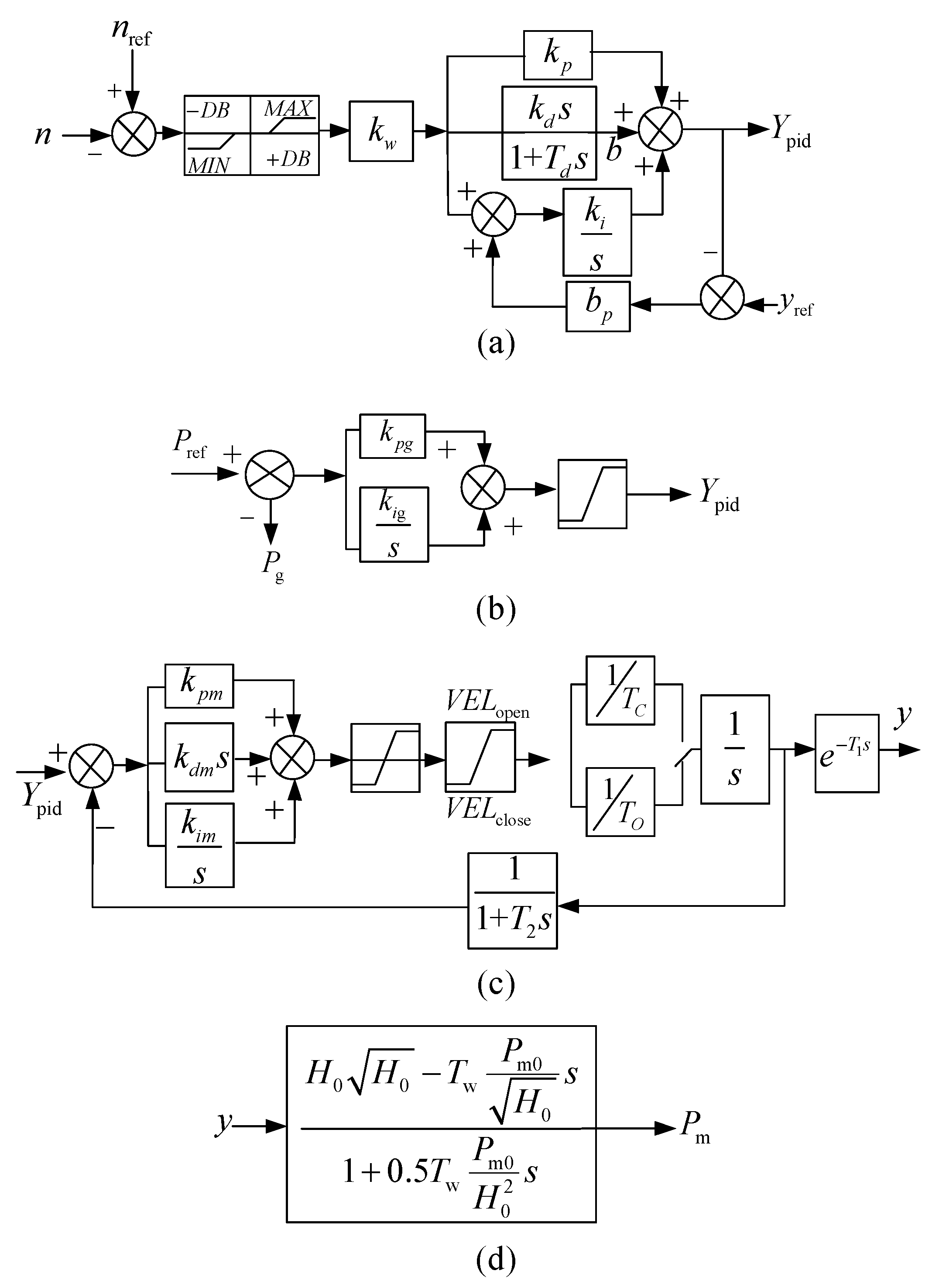
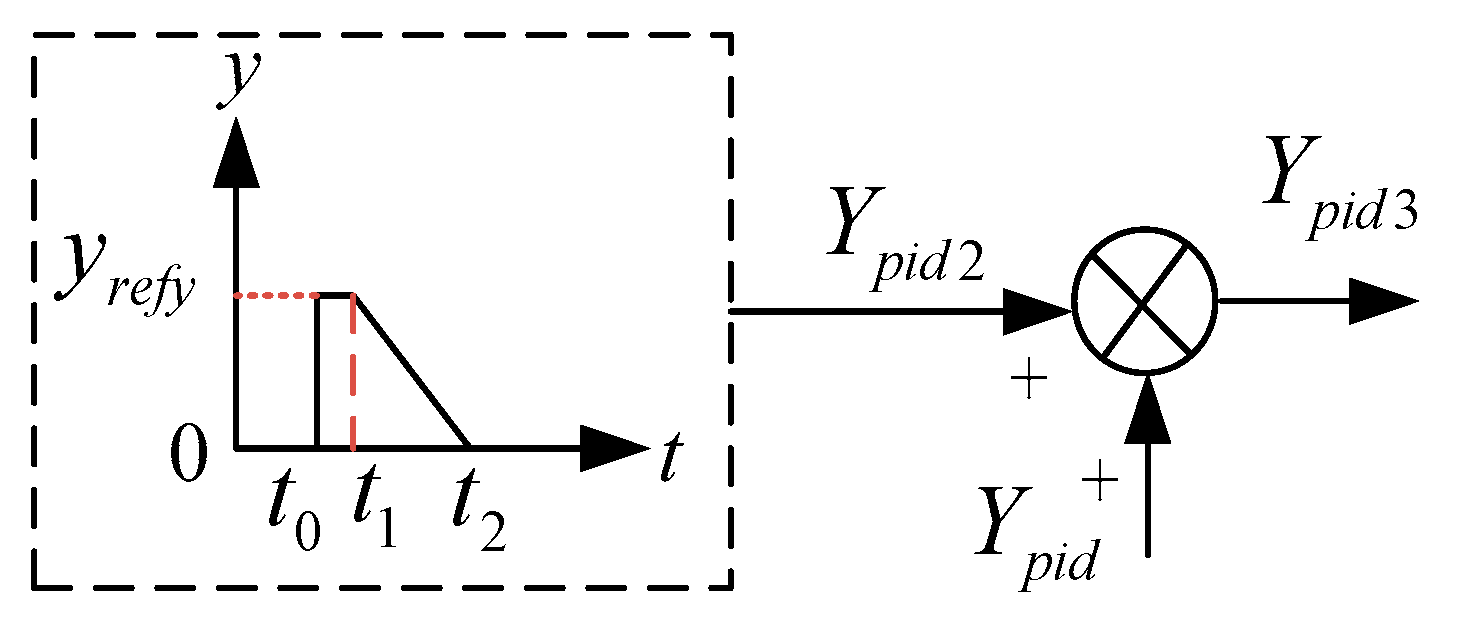
Figure 9 illustrates the PARS, which is implemented by integrating an additional guide vane opening adjustment into the existing power regulation PID in
Figure 4b. Initially, a step signal is applied at the onset of the fault ride-through, instantly increasing the guide vane opening. This increment, due to the water hammer effect, reduces the mechanical power, aiding in mitigating DC overvoltage. After peaking in power reversal, the guide vane instruction is progressively decreased to zero, utilizing the water hammer effect for LVRT control. However, frequent activation of this strategy may cause accelerated mechanical wear of the guide vanes.
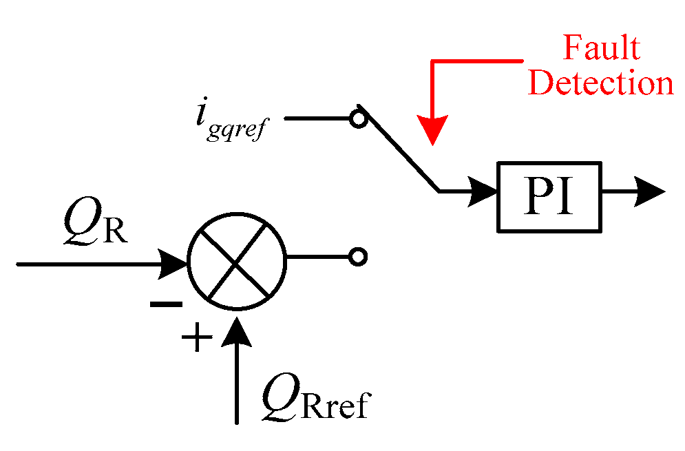
Simultaneously, during the LVRT process, the GSC can inject reactive current to support grid voltage. Consequently, activating reactive current injection control is essential. The criteria for injecting capacitive reactive current during voltage dips are specified below:
where
igqref is the reference value of reactive current during the fault period;
e is the system effective voltage during the fault period;
iN is the rated current of the GSC;
K1 is the proportional coefficient of the dynamic reactive current. The dynamic reactive current control strategy of GSC is shown in
Figure 10. Essentially, it uses variable operating factors to quantitatively compensate for reactive power, ensuring normal and stable power output. Therefore, the active support strategy for reactive current on the grid side can also suppress the increase in DC bus voltage.
Considering that the use of a crowbar circuit can lead to energy waste in the FSC-VSPSU and that long-term operation of the resistor may cause overheating or even explosion. However, from the perspective of engineering reliability, the crowbar circuit is also necessary. When using the aforementioned single strategy, it is difficult to achieve satisfactory results. Therefore, a combination of strategies is proposed. Prioritizing the rotor energy storage control strategy allows the system’s excess energy to be stored as rotor kinetic energy. If the fault is severe and the DC voltage exceeds the allowable value of 1.1 pu, the crowbar circuit should be activated to avoid excessive DC bus voltage. If the DC voltage remains above the tolerable value even after applying the crowbar circuit, the power anti-regulation strategy should be triggered. Meanwhile, reactive current injection control should be activated during the LVRT control.
4.3. LVRT Strategy in Pumping Conditions
During a low-voltage process of the system under pumping conditions, the FSC-VSPSU faces the problem of insufficient energy and low DC voltage. This may prevent the unit from effectively pumping water, resulting in increased vibration and oscillation. To address this issue, the optimal solution would be to increase DC energy storage. However, this would significantly raise the investment costs for power plants. From a technical and economic perspective, it is recommended to use protection methods instead. These protection methods could involve low power, low voltage, or other forms of protection, with specific settings determined based on the unit’s actual situation. The low power protection is described by Equations (16) and (17).
where
PST is the low power action setting value and
PP is the rated power consumed by the pump. The action time limit is the inertia time of the water flow after the pump is powered off, usually 1–2 s. Low power protection can be set according to (15), and it can also be set according to (16).
where
PN is the rated power of the generator. After the low power protection action, the water pump stops. There are various principles for implementing pump protection, and this paper will not discuss them in detail.
Similar to the power generation condition, GSC can also provide reactive power support. Therefore, in the event of a power grid failure under the pumping condition, GSC should prioritize providing reactive power support. When the voltage or power drops too low to meet the normal pump operation, it is permissible to disconnect the pump from the power grid.
4.4. HVRT Strategy in Generation Condition
Based on previous analysis, regardless of the operating conditions, high voltage faults cause DC overvoltage, GSC overmodulation, and power imbalance under all operating conditions. LVRT strategies from power generation scenarios are applicable to address HVRT issues. Overmodulation typically occurs when grid voltage surpasses the GSC’s controllable range. Therefore, regardless of the unit’s operating conditions, injecting a certain amount of inductive reactive power can help reduce the AC voltage of the GSC. Similar to reactive power compensation in LVRT, HVRT can also adopt the reactive power compensation strategy. The reference value of reactive current is as follows:
If the power grid experiences excessive overvoltage, transient power imbalances can significantly raise bus voltage. To keep DC voltage within safe limits, the DC crowbar circuit can dissipate excess energy using the dynamic braking resistor.
4.5. HVRT Strategy in Pumping Condition
Under pumping conditions, the unit behaves such as an adjustable load. An increase in grid voltage leads to a significant rise in the power consumed by the pump. Simultaneously, due to the overmodulation of the converter, there will be an overvoltage on the DC side. The correlation between pump power and speed is detailed in Equation (19).
where subscripts 1 and 2 represent two operating points at different speeds.
P is the power consumed by the pump, and
n is the unit speed, with pump power proportional to the cube of the unit speed. Therefore, a slight adjustment in speed can result in a significant power adjustment. During high voltage conditions, rapidly increasing the pump speed can also help to consume the increase in grid-side power caused by the increase in grid voltage. The rapid acceleration strategy of the pump is the same as the rotor kinetic energy control strategy shown in
Figure 8. In addition, it can also be used to reduce DC overvoltage. Similar to power generation conditions, reactive power compensation and crowbar circuits are also applicable.
5. Simulation Verification
A simulation model of the FSC-VSPSU, as shown in
Figure 1, is constructed in PSCAD/EMTDC. The correctness of the low and high voltage fault characterization of the grid and the effectiveness of the proposed LVRT and HVRT strategies will be verified in this section.
Table 1 and
Table 2 provide the simulation parameters of the FSC-VSPSU.
Table 3 shows the clear experimental steps.
5.1. Simulation Characteristics of LVRT
Firstly, the LVRT characteristics are simulated. The system voltage signal command is shown in
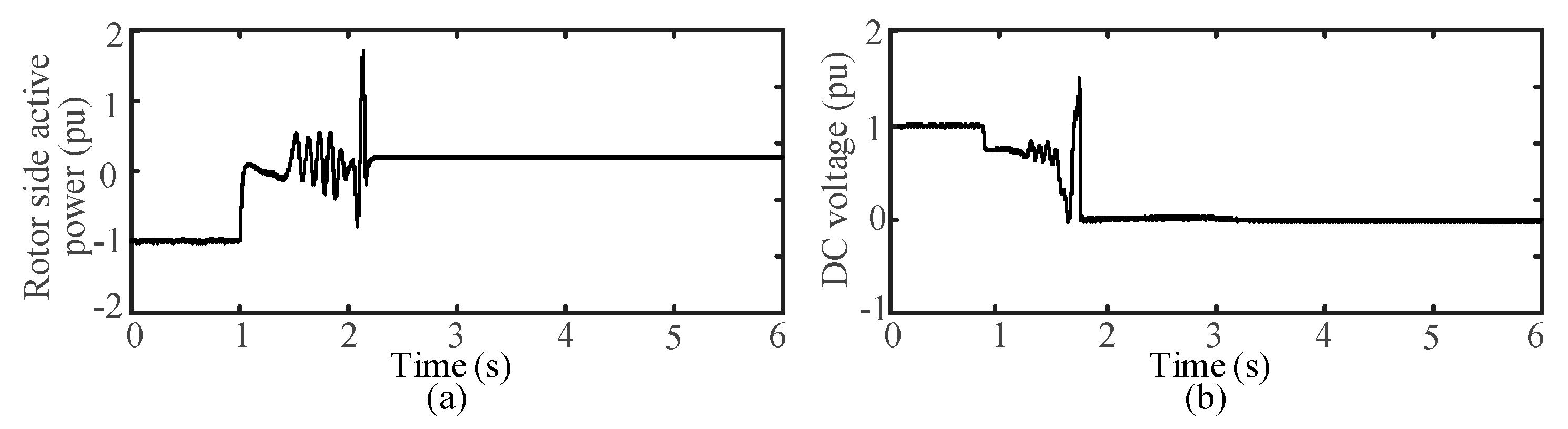
Figure 11. The simulation results under low voltage faults in the power generation and pump conditions without applying fault ride-through control measures are shown in
Figure 12.
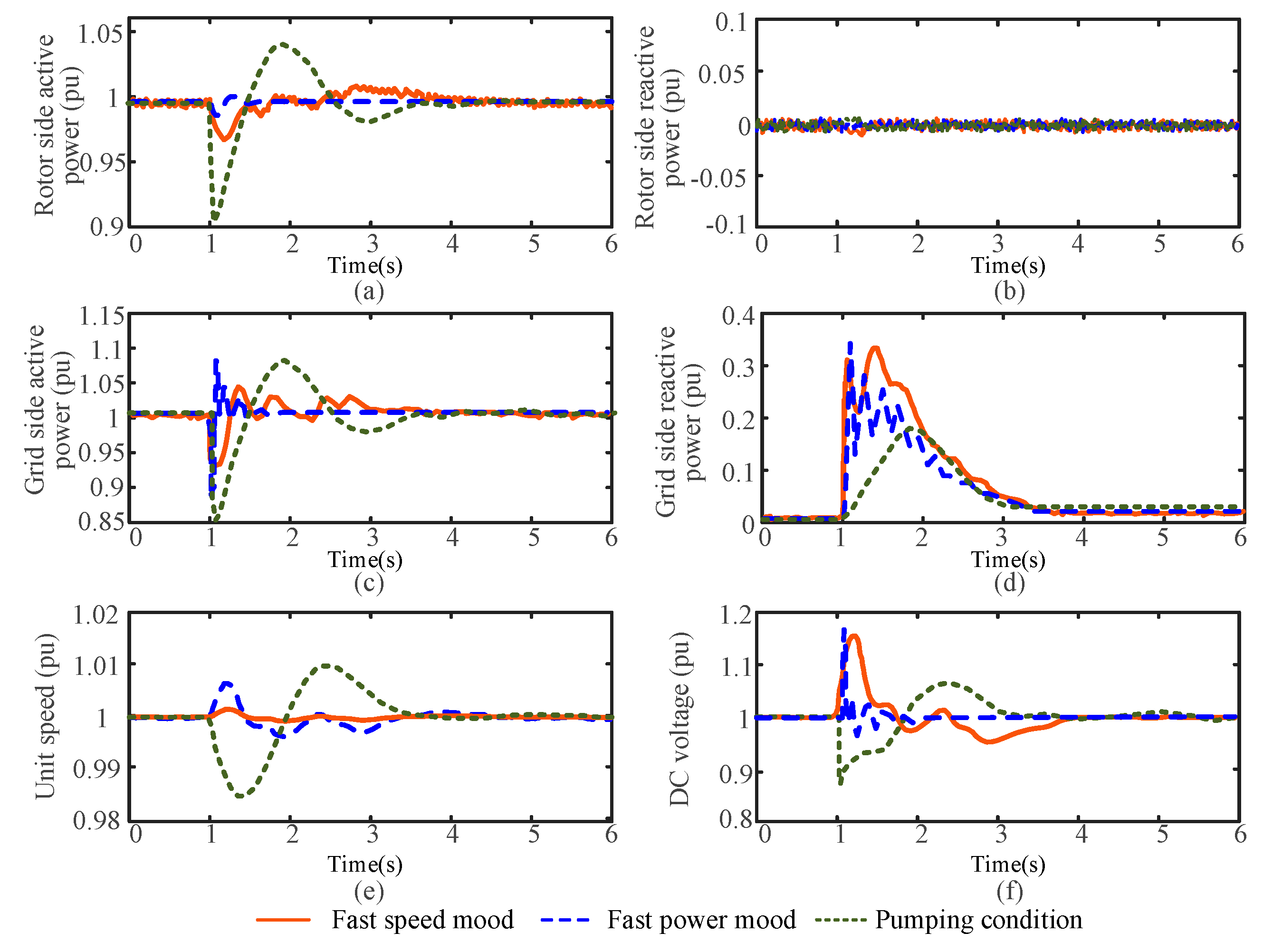
When using the fast speed mode for power generation, the active power on the grid side significantly decreases. Due to the inability to decouple reactive power from active power during transient processes, the reactive power briefly increases before returning to zero. The power on the rotor side slightly decreases and the DC voltage increases significantly, with a slight change in the rotational speed. When using the fast power mode for power generation, the characteristics of active and reactive power changes on the generator side and the unit speed are consistent, but the magnitude of the changes varies due to differences in control modes.
For clear comparison, the power direction was not distinguished under pumping conditions. Under pumping conditions, the active power on the grid side decreases significantly and oscillates. The active power waveform on the generator side is similar to that on the grid side, while the unit speed and DC voltage decrease significantly. The simulation results align with the analysis of LVRT characteristics presented in
Section 3.1.
5.2. Verification of the LVRT Strategy
This section verifies that the proposed combination of the LVRT strategies can meet the fault ride-through requirements mentioned in
Section 4.1. The system voltage signal command is shown in
Figure 13.
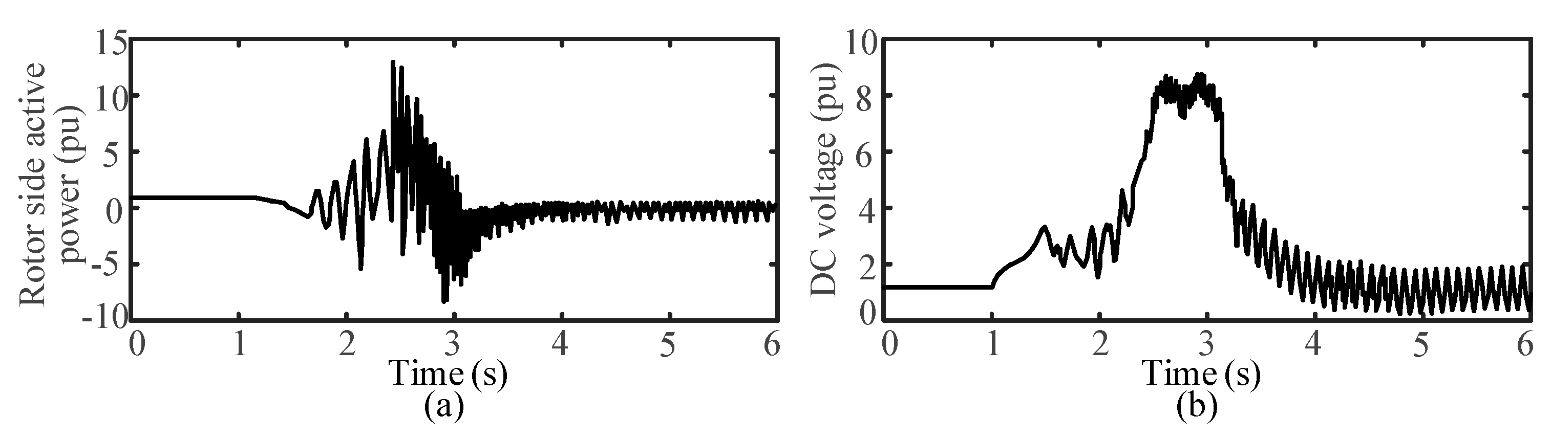
- (1)
In the fast speed mode
Figure 14 shows the simulation curve for fast-speed mode under power generation conditions without any measures. The excessive energy on the rotor side causes the DC voltage to rapidly increase, making it impossible for FSC to operate stably, resulting in the loss of stability of the unit.
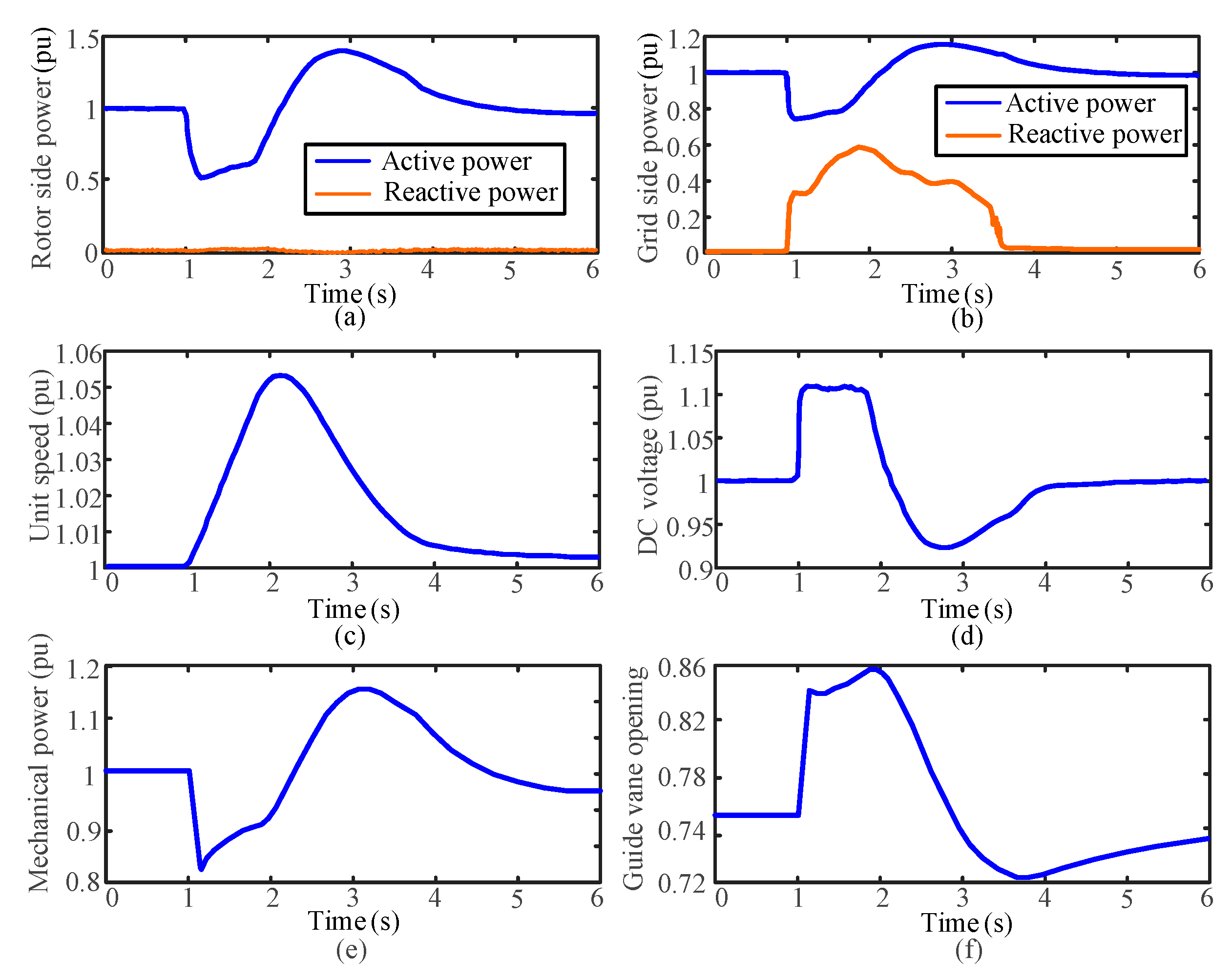
Figure 15 shows the effect of investing in the combination strategy. As shown in
Figure 15c, the rotor speed increases even more, reaching 1.052 pu. The guide vane opening as shown in
Figure 15f instantly increases to 0.84 pu, which reduces the power input on the machine side to a certain extent. The DC crowbar circuit is triggered, maintaining the DC bus voltage at 1.1 pu during the fault period, as shown in
Figure 15d. The GSC outputs reactive power, and the unit remains stable. The DC voltage is within a safe range, and the LVRT control effect is good after the combination strategy is put into use.
- (2)
In the fast power mode
Similar to the fast-speed mode, low-grid voltage can cause unit instability. The unstable waveform is similar to
Figure 14.
Figure 16 shows the effects of applying the combination strategy. The introduction of the fast power reduction strategy causes rotor-side power to rapidly decrease to 0.78 pu. Due to the governor controlling the unit speed at this time, its adjustment speed is slow. Therefore, the power imbalance caused a significant increase in the unit speed. In addition, the GSC outputs reactive power to increase grid voltage, keeping the unit stable and the DC voltage within a safe range.
- (3)
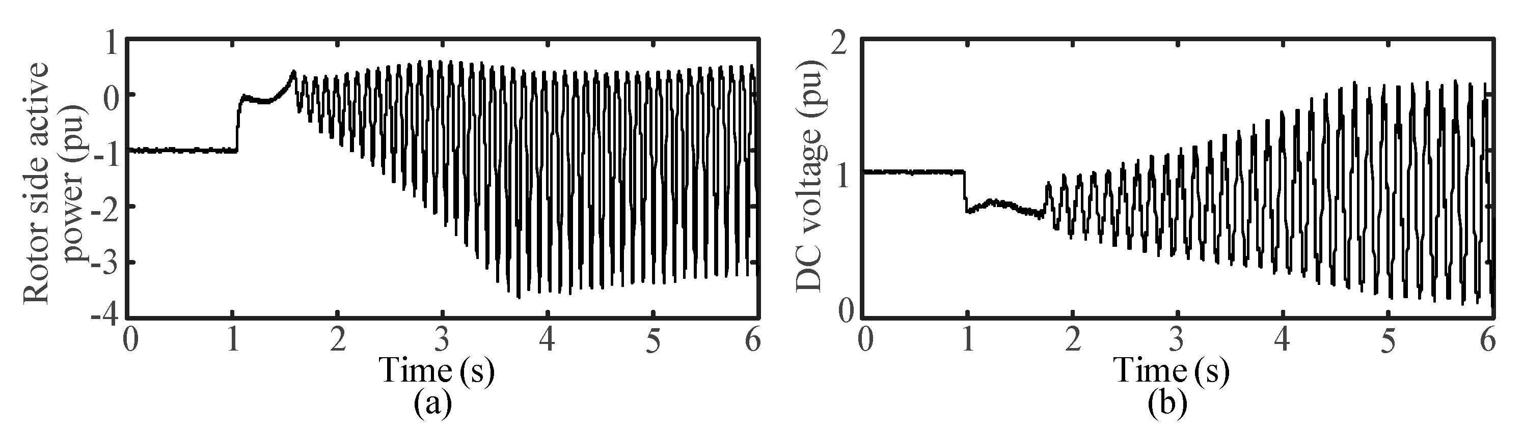
In pumping condition
Similar to power generation conditions, low-grid voltage can cause insufficient energy for the pump and instability of the unit. After adopting low-power protection measures, the water pump can be quickly shut down to ensure unit safety, as shown in
Figure 17 and
Figure 18.
5.3. Verification of the HVRT Strategy
This section verifies that the proposed combination of the HVRT strategies can meet the fault ride-through requirements mentioned in
Section 4.1. The system voltage signal command is shown in
Figure 19.
- (1)
In fast speed mode
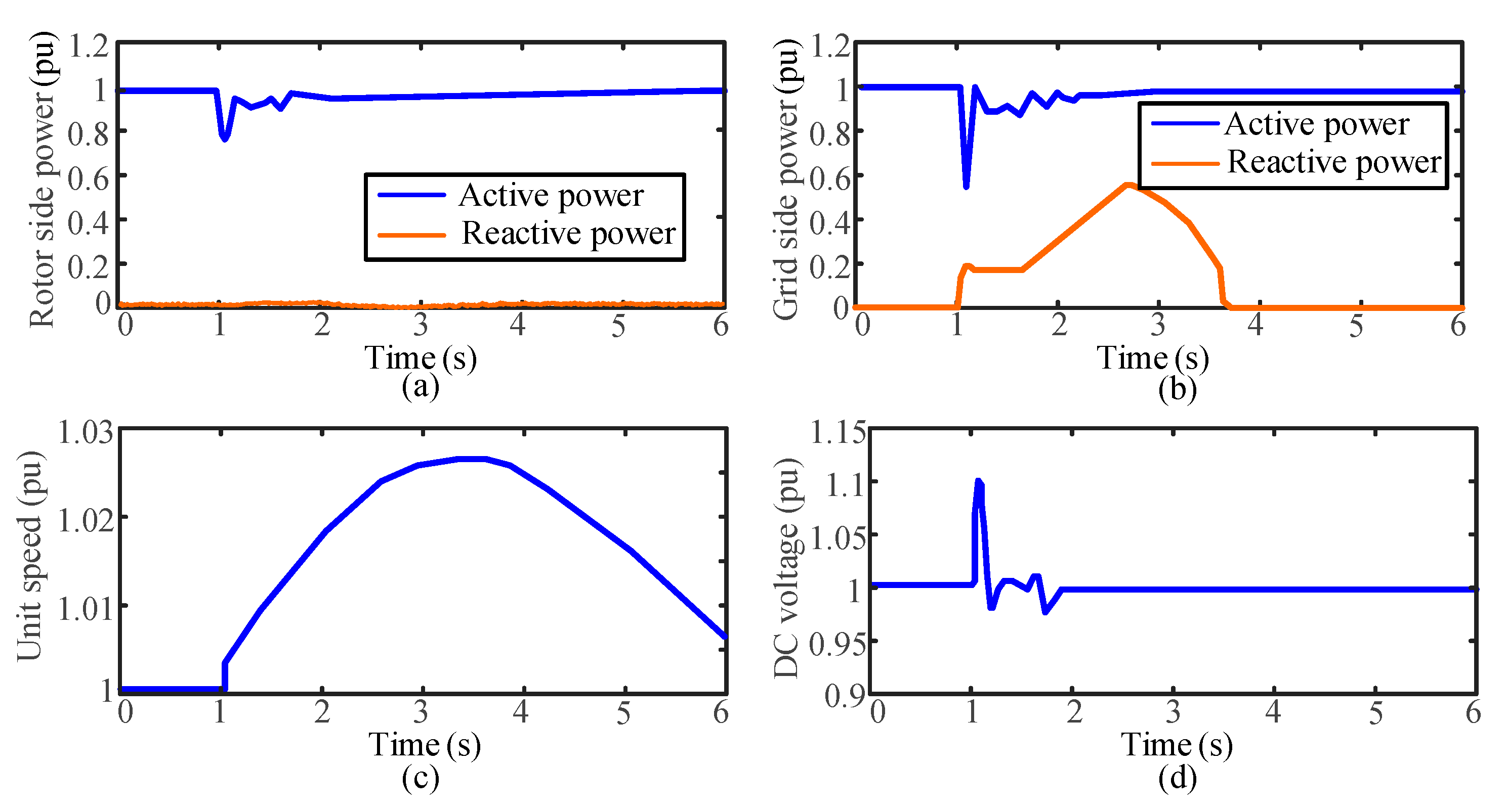
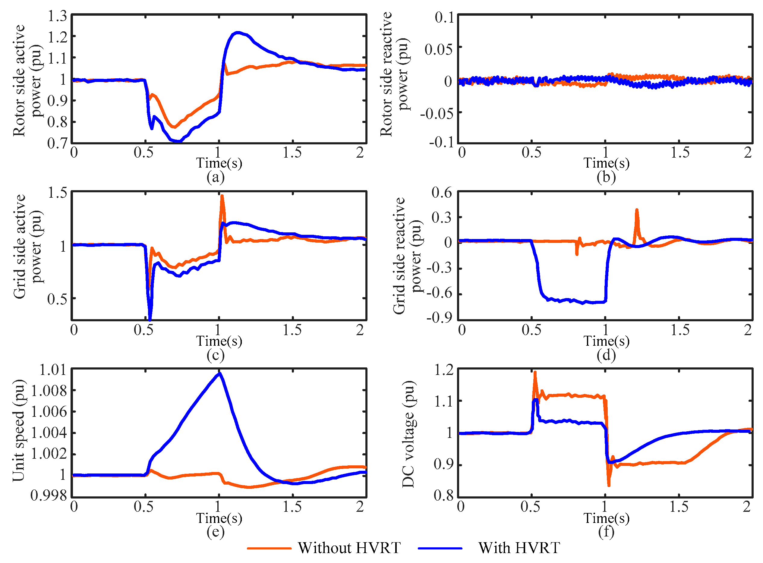
Figure 20 shows the simulation curve of the fast speed mode under power generation conditions before and after the HVRT measures are applied. In this case, the rotor energy storage, reactive power compensation, and power reversal strategies are applied, while the crowbar circuit is not adopted.
During the overvoltage period of the system, there is a significant drop in active power on the grid side, and the active power on the rotor side also decreases. The maximum DC voltage reaches 1.2 pu. With the HVRT strategy, the rotor speed increases to store the unit energy to reduce the rotor-side active power and the power imbalance. The GSC outputs reactive current to avoid overmodulation. The DC voltage decreased from 1.2 pu to 1.1 pu and immediately stabilized at 1.03 pu.
- (2)
In fast power mode
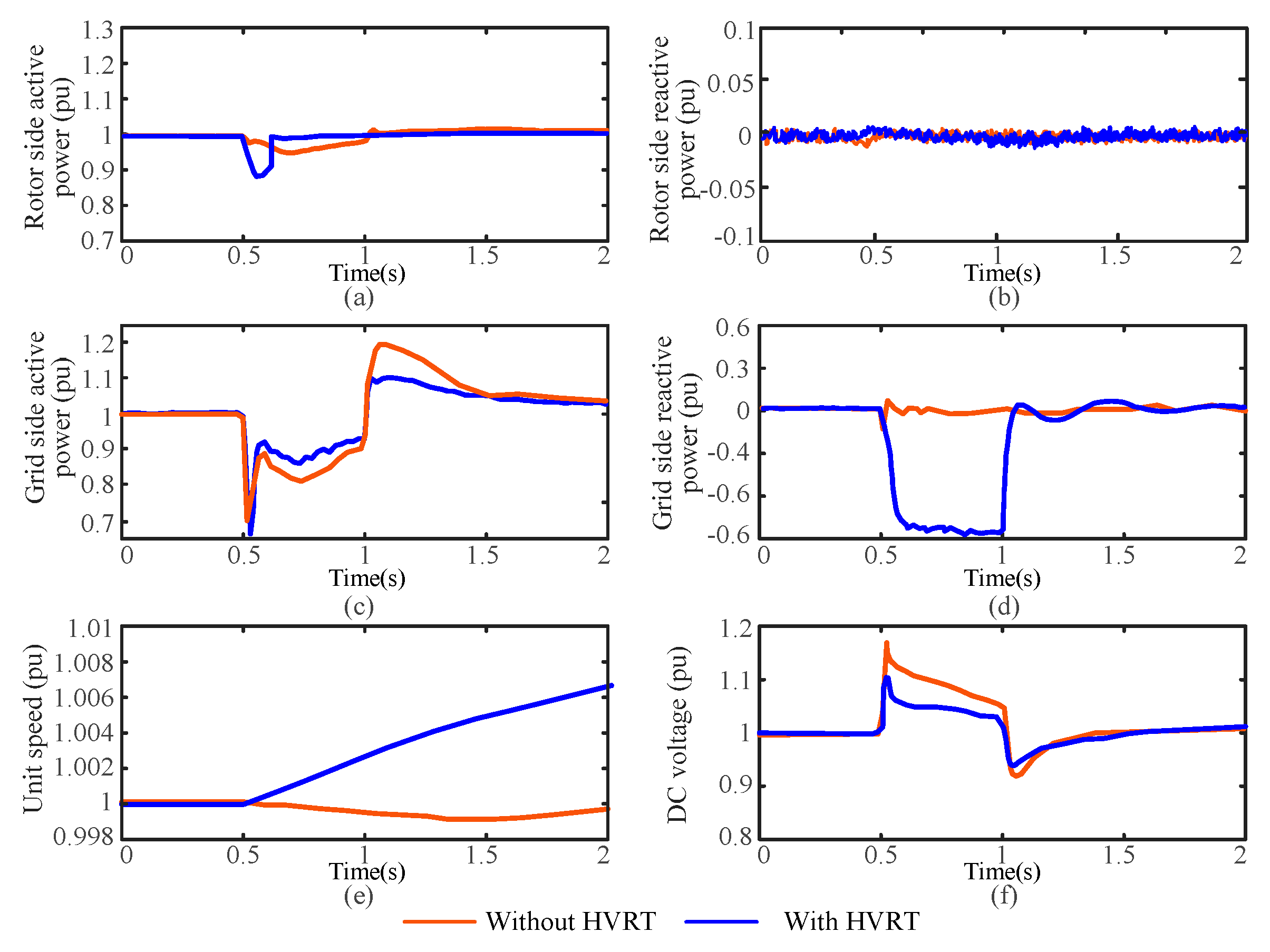
Figure 21 shows the simulation curve of the fast power mode under power generation conditions before and after the HVRT measures are applied. In this case, the rotor energy storage, reactive power compensation, and fast power drop strategies are applied. The crowbar circuit is not adopted.
Without control strategy, the active and reactive power on the rotor side remain almost unchanged, and the unit speed does not change. The active power on the grid side decreases significantly during the overvoltage period, and the transient voltage of the DC bus rises to a maximum of 1.17 pu. With the proposed HVRT strategy, the GSC outputs inductive reactive current to maintain the grid voltage. Due to the power speed reduction strategy, the active power on the rotor side decreases to 0.87 pu during the fault period, and the maximum DC voltage drops from 1.17 pu to 1.1 pu.
- (3)
In pumping condition
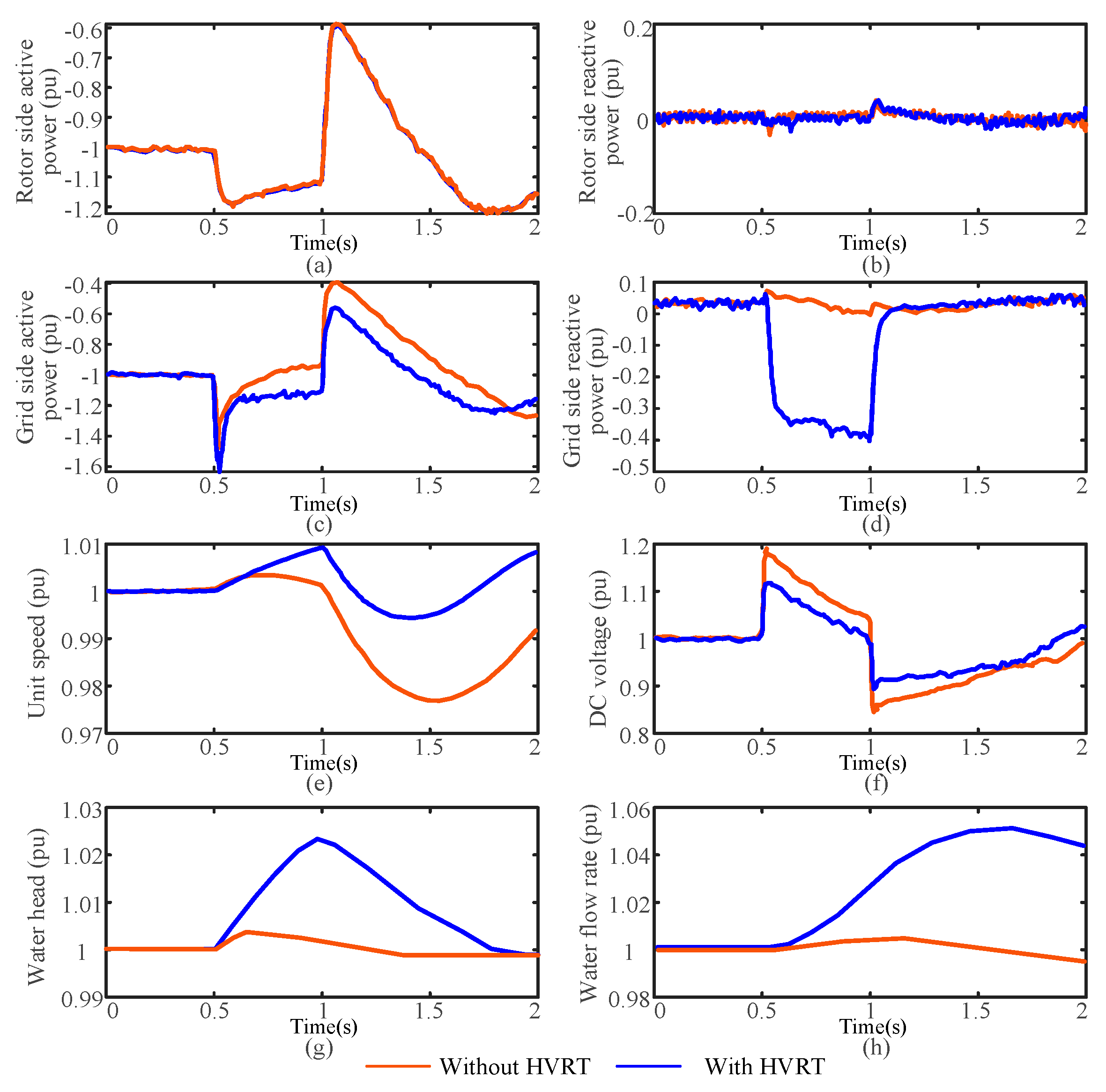
Figure 22 shows the simulation curve of the pumping condition before and after the HVRT measures are applied. In this case, the rotor speed increases, and reactive power compensation strategies are applied. The crowbar circuit is not adopted.
During the fault period, the active power on both rotor and grid side increased significantly, the unit speed fluctuated greatly, and the changes in water head and flow rate are relatively small. The maximum DC bus voltage rises to 1.2 pu. With the proposed HVRT strategy applied, the rotor is precisely accelerated, increasing the active power consumption on the rotor side and reducing the unbalanced power stored in the DC capacitor. Combined with reactive power compensation of the inverter, the DC voltage decreases from 1.2 pu to 1.1 pu. The water head of the unit increases to 1.024 pu, and the pumping flow rate increases to 1.045 pu.
The above simulation results verify the correctness of the fault analysis during the high voltage period, as well as the effectiveness of the proposed HVRT combination strategy. However, it should be further noted that although the DC overvoltage decreased to 1.1 pu after implementing control measures, it is still recommended to configure a crowbar circuit in engineering to ensure the unit’s safe operation.
6. Conclusions
This paper analyzes the characteristics of the FSC-VSPSU under low voltage and high voltage fault conditions. Based on this analysis, the fault ride-through requirements and control strategies are proposed. The dominant factor causing DC overvoltage during low-voltage events is power imbalance. The high-voltage process is mainly affected by the overmodulation of FSC and the power imbalance. In order to provide better support for the renewable energy or the power grid, it is recommended that the fault ride-through ability of the FSC-VSPSU is stronger than that of wind turbines.
In terms of LVRT, the critical issues include power imbalance and DC overvoltage or undervoltage. Under power generation conditions, adopting a combination strategy of power droop, reactive power compensation, and crowbar circuits is advocated. In fast-speed mode, a strategy integrating rotor kinetic energy regulation, power reversal, reactive power compensation, and crowbar circuits is suggested. Under pumping conditions, it is prudent to implement low power protection strategies. The application of the proposed LVRT strategy enables the FSC-VSPSU to handle low voltage faults down to a minimum of 0.15 pu, actively bolstering the grid voltage and reducing potential peak DC voltage to a stable 1.1 pu.
In terms of HVRT, the primary issues involve the DC overvoltage caused by the overmodulation of the converter and the power imbalance. The strategies for power generation conditions are still applicable. Under pumping conditions, fast speed regulation can effectively solve the problems of power imbalance and DC overvoltage during fault processes. It is recommended to adopt a combination strategy of fast speed regulation, reactive power compensation, and crowbar circuit. Implementing the proposed HVRT strategy ensures that the FSC-VSPSU can endure high voltage faults up to 1.35 pu, actively supporting the grid voltage while preventing overmodulation, and maintaining DC voltage within a safe range of 1.1 pu.

 ,
, 

