1. Introduction
The advantages of using carbon in electrical applications are well documented and include low cost, a broad potential window, relatively inert electrochemistry, and electrocatalytic activity for various redox reactions [
1]. Several reviews and monographs have highlighted the use of carbon as an electronic material, focusing particularly on classical carbon materials such as graphite, glassy carbon, and carbon black [
2,
3,
4]. Additionally, mesoporous carbon, a high-surface-area graphitic material, is produced through the “carbonization” or pyrolysis of carbon-rich precursors like sucrose [
5,
6].
Carbon polymers exhibit a broad range of conductivities due to the diverse nature of carbon materials, making them suitable for electronic applications. In this study, carbon particles are utilized as the foundational electronic components, leveraging the properties of high-surface-area carbon materials. This technique has the potential to be widely applied in developing new circuit components and advancing electronic technologies and processes.
1.1. Physisorption and Conductivity
When heating elastic polymer composite materials doped with carbon or activated carbon powder, the low-melting-point polymer evaporates completely, leaving behind the carbon, which maintains its mass and size. This process involves physisorption, also known as van der Waals adsorption, rather than chemisorption, as it does not involve any chemical reactions between the carbon and the polymer.
1.2. Adsorptive Reaction of Elastic Polymer Composite Material and Carbon Powder
Adsorption refers to the process where a material interface attracts and temporarily holds medium particles from its surroundings. Materials that can adsorb particles on their surface are known as adsorbents, while the particles being adsorbed are called adsorbates. In this study, graphite and activated carbon are used as conductive adsorbents in solid form. The surface of these carbon materials can adsorb molecules from the elastic polymer composite material, leading to adsorption by both the internal molecules of the polymer and the carbon molecules.
This dual adsorption creates opposing forces, which can reduce the surface tension of the carbon. As a result, the interaction between the carbon adsorbent and the polymer composite material is enhanced, potentially improving the composite’s properties and performance.
However, the elastic polymer composite material’s molecules adsorbed on carbon’s surface are not static because the heated perturbation or elastic collisions of these molecules can cause them to deviate from the surface of the adsorbent and return to the surrounding media [
7,
8]. This phenomenon is called desorption. Adsorption and desorption are reversible reactions; physisorption also has the property of surface adsorbent saturation. At a fixed temperature, adsorption can reach equilibrium with the reaction time, which is named adsorptive equilibrium. Adsorptive equilibrium can be acquired by the basic dynamic model and the statistical mechanics method. The brief expression is shown as
2. Materials and Methods
2.1. The Base Material of Elastic Polymer Composite Materials
Using the soft, insulating, and durable properties of elastic polymer materials, we design devices that fit closely and provide flexibility and resilience. However, these elastic polymers are typically non-conductive. Through research and experimentation, it was discovered that polysiloxy polymers, which are often silicones, exhibit strong adsorption properties.
Polysiloxy polymers are characterized by their silicon–oxygen backbone, with the basic repeating unit being –Si–O–. To impart electrical conductivity, these polymers are doped with a high concentration of graphite particles. Silicones are known for their stable, non-toxic structure and rubber-like physical properties, making them an ideal base material when combined with conductive fillers like graphite. The structural unit of silicones is shown in
Figure 1a.
Silicon atoms in polysiloxy polymers are bonded with various organic functional groups, such as methyl, ethyl, and phenyl, making these polymers semi-organic and semi-inorganic. Oxygen plasma treatment can enhance the –SiO
n(OH)
4−n groups on the silicon surface, with the degree of modification being influenced by the intensity of the oxygen plasma and the treatment duration [
9].
To investigate the electrical properties related to carbon doping concentrations, different doping levels of the polymeric rubber-like material were produced. Highly adsorptive carbon was chosen for doping within silicon-based polymers and polyurethane rubber. The repetitive structural units of these materials are depicted in
Figure 1b as thermoplastic rubber (TPR). This approach aimed to explore how varying concentrations of carbon influence the electrical properties of the composite material.
2.2. The Analysis of SEM
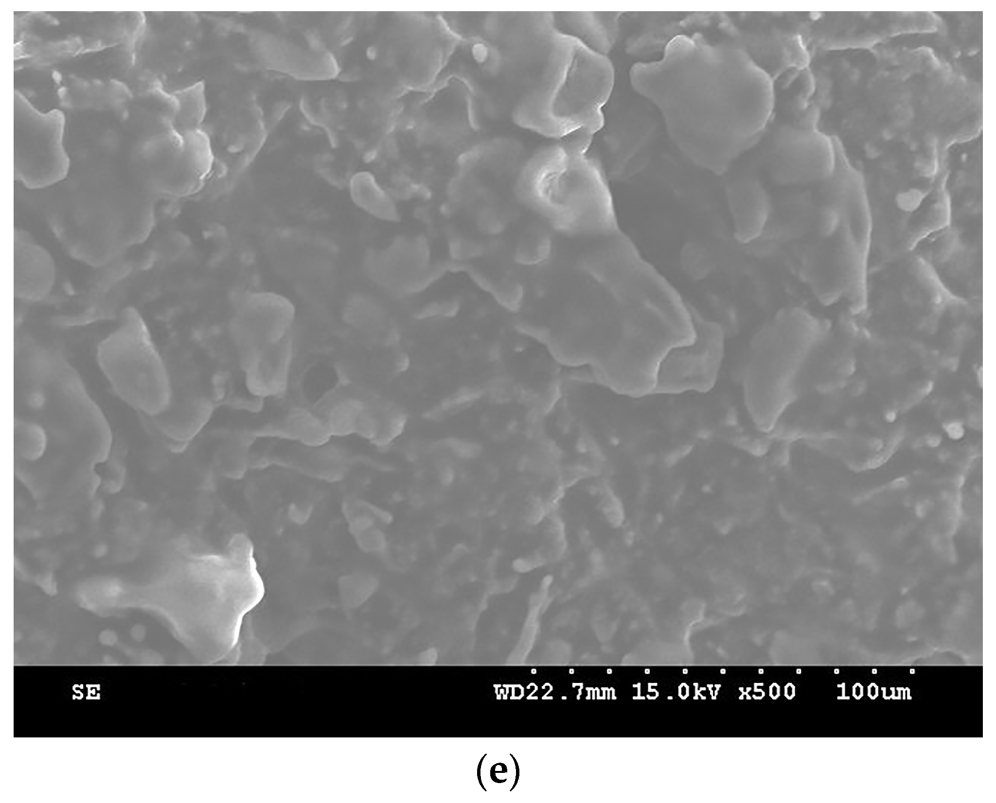
The molecular packing of polymers significantly impacts their physical properties. Carbon physisorption reduces the intermolecular distance while substantially increasing intermolecular attraction. The adsorption behavior at different doping concentrations in elastic polymer composite materials was observed through SEM, as shown in
Figure 2. These images highlight the secondary bonding forces within the polymer and the high residual forces due to macromolecular weight. When the carbon dopant concentration is too high, it creates a strong attraction, leading to tightly packed molecules arranged in a highly regular structure. However, due to the polymer’s macromolecular weight and structural defects, perfect parallel alignment is not achievable.
Carbon atoms are composed of three sp
2 hybridized orbitals, which interact when in close proximity. In a graphite structure, carbon atoms have an electronic configuration of 2S-2P. Each layer of carbon atoms forms strong σ bonds with three adjacent carbon atoms. The bonding in the vertical direction between layers is facilitated by unhybridized P orbitals forming π bonds, which are relatively weak, resulting in a very narrow energy gap. This narrow gap allows valence electrons to move easily within the π orbitals, providing good electrical conductivity. SEM images from
Figure 2a–e show that increasing the concentration of carbon powder enhances the physisorption function. When the distance between carbon particles approaches the van der Waals radius (0.3354 ± 0.0001 nm), valence electrons begin to overlap intermolecularly, significantly increasing electrical conductivity.
2.3. Doping Concentration of Carbon and Electrical Conductivities
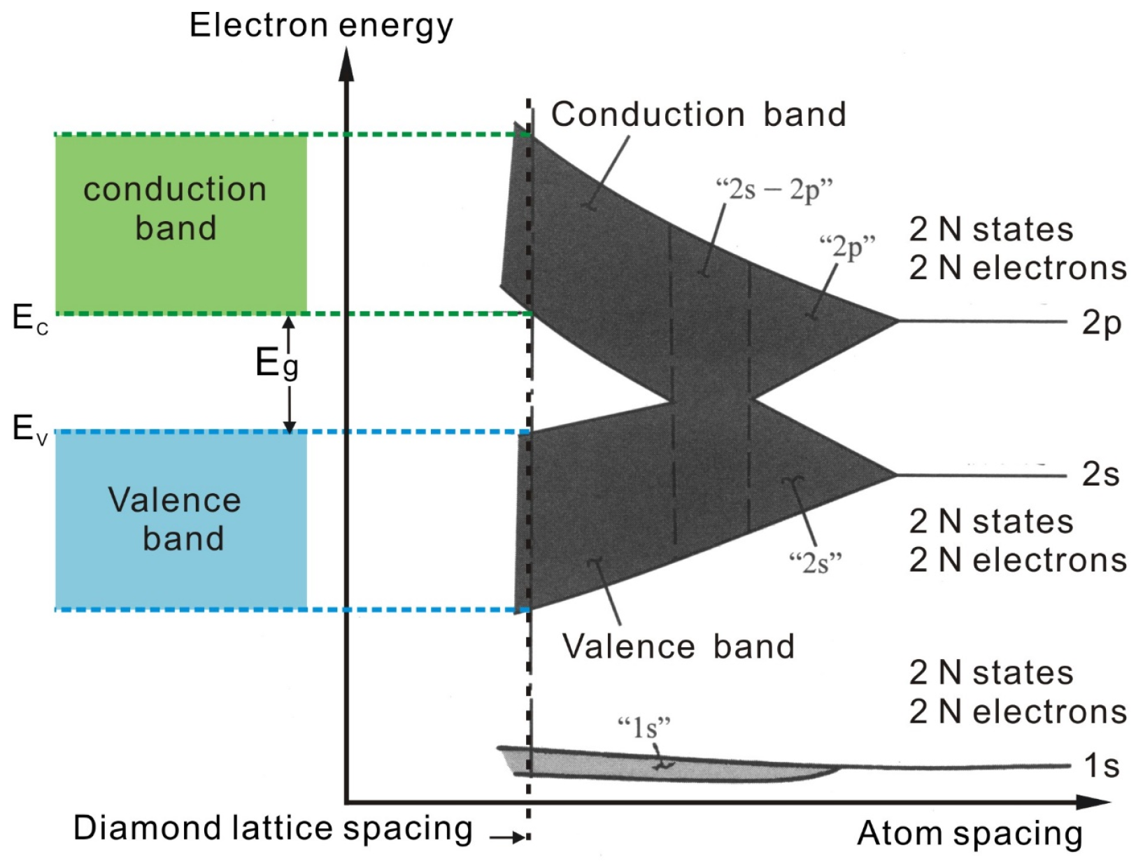
When enough carbon atoms are close to each other as shown on
Figure 3, they will form a continuous permissible energy level. This energy level can cause the electrons which were fixed on the valence band to move interatomically. It is not possible to distinguish which atoms these electrons belong to, which is called electron sharing. These electrons have both around atomic and communization movement characteristics, so they will split into the energy levels of many groups. The energy levels of each group are very close, so the energy levels turn into approximate continuity, while the composition of a particular band width, with this kind of energy level arranged as close-order belt shape, is called the energy band.
An important consideration regarding electrode materials is the concentration of electronic states (DOS), which varies greatly for different forms of carbon. The high conductivity of metals results from the combination of a large number of atomic orbits to form bands with a high concentration of electronic states.
Sole atoms that only have one energy level are those where the electron is bound on the energy level. When another atom is very close, the atoms interact and the energy level splits into two, resulting in a degenerated state. If there is one more atom approaching, it will split into three energy levels. As N’s isolated atoms are brought together to form a solid, they will split into N’s energy levels and become very close to each other. The electronic structure of each individual carbon atom is 1S22S22P4, so a single carbon atom has two 1S states, two 2S states, four 2P states and higher energy state. Ns’ carbon atoms will have 2 × Ns’ 1S states, 2 × Ns’ 2S states and 4 × Ns’ 2P states.
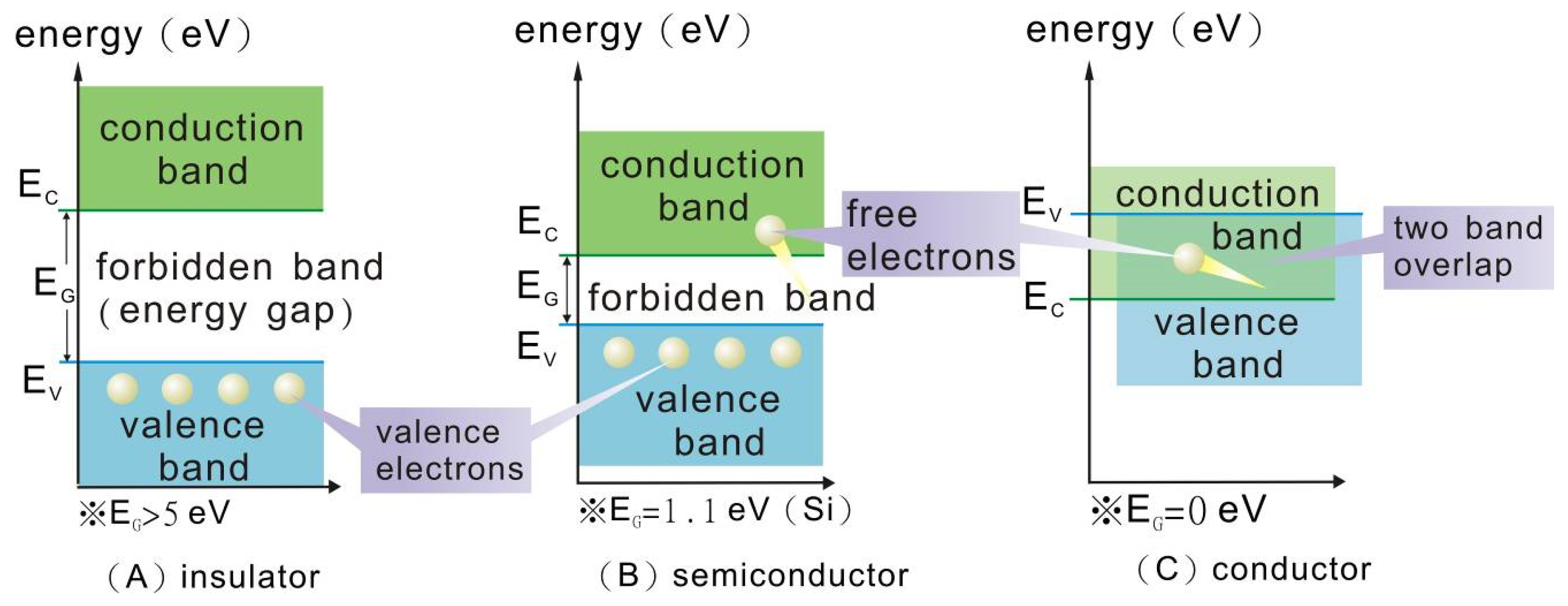
Figure 4 is a solid model of the energy gap; the region between different energy levels without any electronics is called the energy gap or forbidden band. The width of the energy gap is the indicator of the difference between the insulator, semiconductor, and conductor. The carbon atoms of graphite’s structure have very good electric conductivity because there is not an energy gap between the valence band and conduction band. Electrons move freely without changing energy, and metallic conduction follows Ohm’s law [
11].
When the distance between carbon atoms is smaller, then the carbon atoms will form a diamond lattice as
Figure 5 shows. The 2S-2P energy level can be dispersed to two energy levels and possess 8 × Ns’ states. The top energy level is called the conduction band which has 4 × Ns’ states, and the bottom energy level is called the valence band, which also has 4 × Ns’ states. These two energy levels are separated by a very wide energy gap, a large band gap of more than 5 eV, so undoped diamond is normally electrically insulating and cannot be used as an electrode material [
12]. But as with other large-band-gap materials, diamond can be made conductive by doping it with certain elements [
13].
Diamond electrodes that make use of the surface transfer doping effect have been named surface conductive diamond (SCD) materials [
14]. The electroanalytical techniques for which diamond electrodes have been applied are called amperometric detection [
15,
16,
17,
18,
19,
20,
21,
22,
23,
24,
25,
26,
27,
28,
29,
30,
31,
32,
33,
34,
35].
Figure 5.
Diamond lattice, for example, Si, Ge, C…, etc. (
A) Tetrahedron bond in diamond lattice. (
B) A tetrahedron bond. (
C) Schematic two-dimensional representation of a tetrahedron bond [
36]. Explanation: The points in Figure (
C) depict the electrons shared within the covalent bond.
Figure 5.
Diamond lattice, for example, Si, Ge, C…, etc. (
A) Tetrahedron bond in diamond lattice. (
B) A tetrahedron bond. (
C) Schematic two-dimensional representation of a tetrahedron bond [
36]. Explanation: The points in Figure (
C) depict the electrons shared within the covalent bond.
2.4. Infrared Absorption Spectrum Analysis
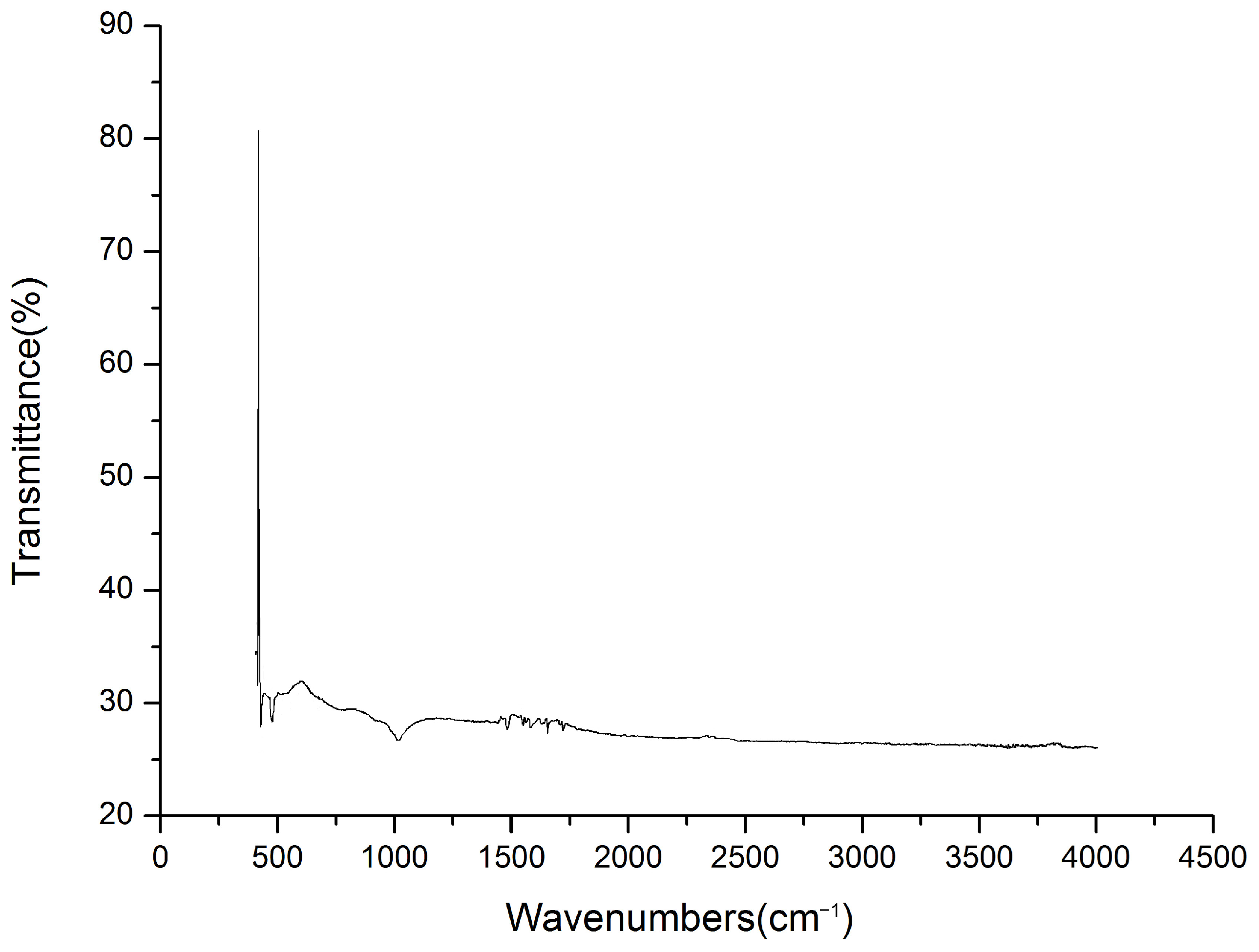
Figure 6 presents the infrared absorption spectrum of the base material, which exhibits four main absorption peaks at the following wavenumbers: 1030 cm
−1, 1600 cm
−1, 2260 cm
−1, and 2315 cm
−1.
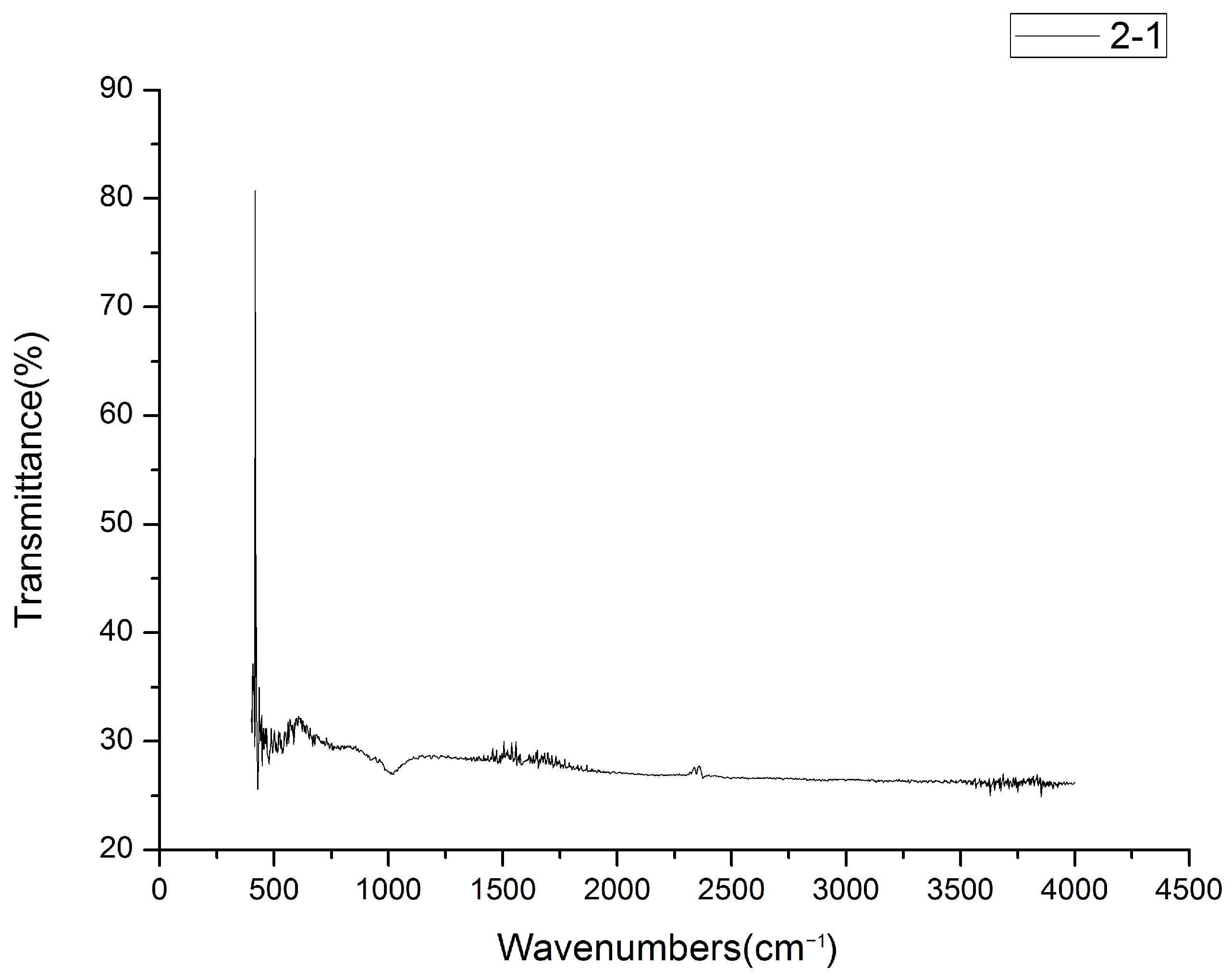
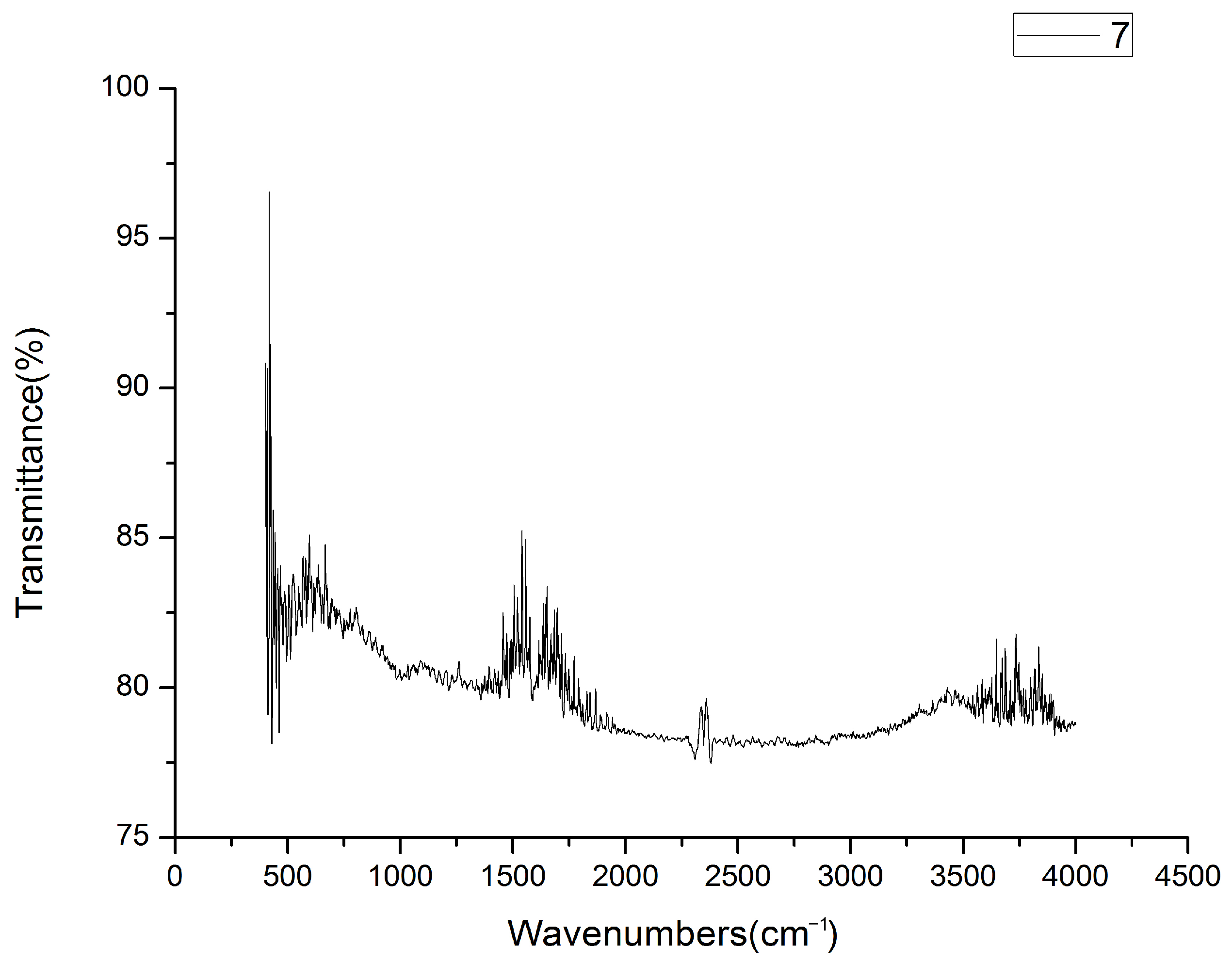
Figure 7 and
Figure 8 illustrate the infrared spectra of elastic polymer composite materials doped with varying concentrations of carbon powder, showing how these peaks shift or change with different doping levels.
As the doping concentration of carbon powder increases, the absorbance of lower energy chemical bonds decreases significantly. Consequently, absorption peaks at wavenumbers less than 1500 cm−1 nearly vanish. The characteristic infrared spectra of the elastic polymer composite materials in this study are primarily attributed to various vibrational modes of chemical bonds, as explained in the following.
2.4.1. The Infrared Spectrum Illustration of C–O Group
The absorption peak corresponding to the C–O group stretching vibration, which is found at 1030 cm−1, diminishes as the concentration of carbon particles in the substrate increases. This indicates an inverse relationship between the C–O group concentration and the carbon particle doping concentration. As the doping concentration of carbon powder rises, the concentration of C–O groups in the base material decreases.
2.4.2. The Infrared Spectrum Illustration of C=C Group
In the characteristic region of the C=C group stretching vibration, the absorption spectrum typically features a single peak near the wavenumber of 1600 cm−1 (6.25 μm). The intensity of this peak is directly proportional to the doping concentration of carbon particles in the substrate. As the concentration of carbon powder increases, the number of C=C groups in the base material also rises, leading to a more pronounced absorption peak in this region.
2.4.3. The Infrared Spectrum Illustration of C≣C Group
At low doping concentrations of carbon powder in the substrate, the absorption spectrum displays a single, reduced absorption peak located at 2260 cm−1. However, at higher doping concentrations, the spectrum reveals two distinct absorption peaks at wavenumbers of 2260 cm−1 and 2315 cm−1, respectively.
2.5. UV/VIS/NIR Spectroscopy
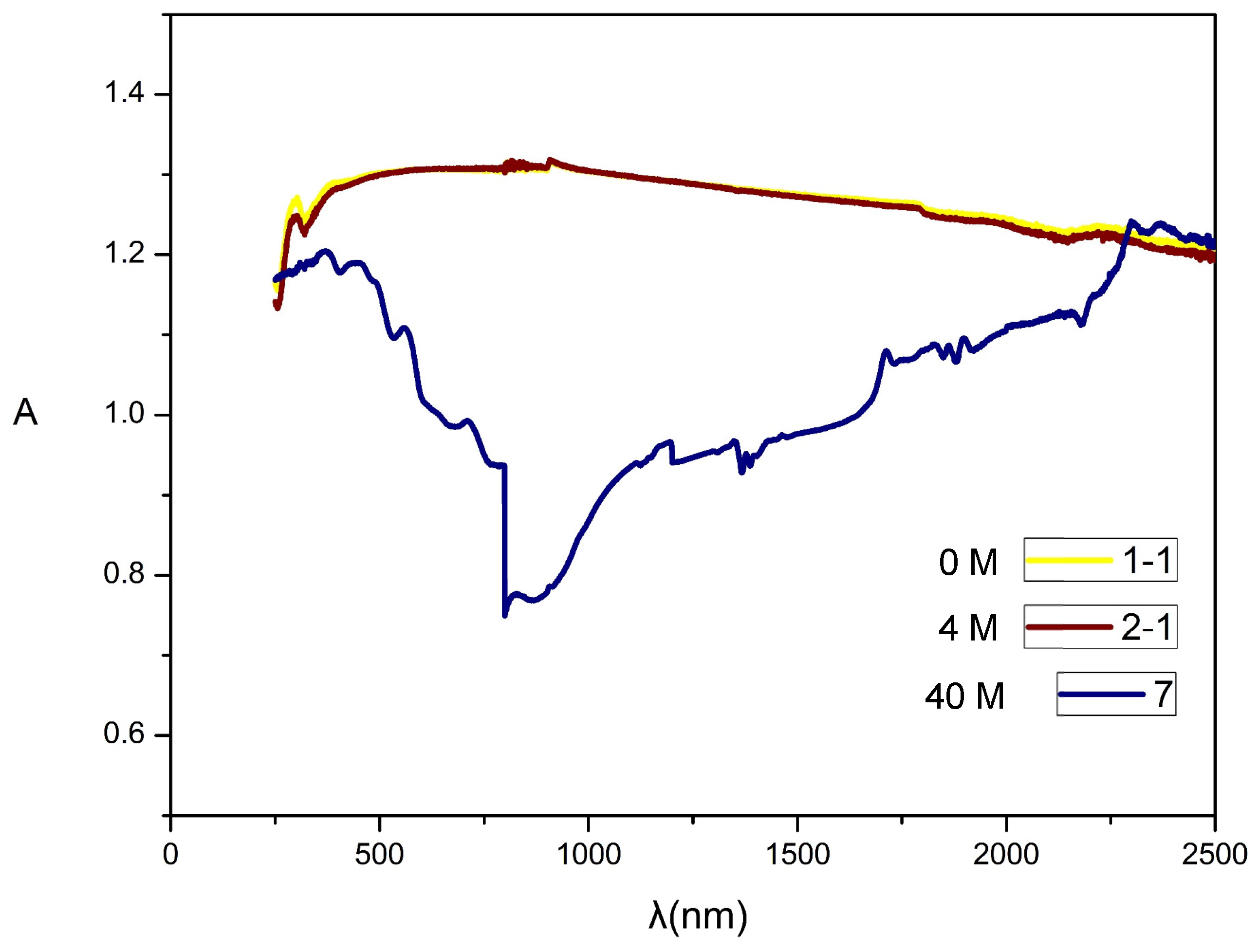
Figure 9 illustrates the UV-VIS-NIR spectroscopy of the base material with varying concentrations of carbon powder doping. The UV-VIS-NIR absorption spectrum reveals a consistent pattern across different doping concentrations, with a common absorption peak at 325 nm. This peak is attributed to the transition of electrons from the valence band to the conduction band within the polymer chain of the elastic polymer composite materials [
37]. As the concentration of carbon powder increases, a stronger absorption peak emerges at a wavelength of 2310 nm.
UV-VIS-NIR absorption spectroscopy provides insights into chemical bonding, particularly in relation to the electronic structures of polymers, including electronic orbitals, valence shells, and molecular configurations [
38,
39,
40,
41,
42]. When the doping concentration of carbon powder in the base material is increased to 40 M, the conductive elastic polymer composite material exhibits a more pronounced absorption peak at 2310 nm. This enhancement occurs because the valence electrons, initially confined to the valence band, transition to the conduction band as the doping concentration rises. The carbon powder’s physisorption contributes to the excitation of these electrons, turning them into free carriers. Consequently, the material’s conductivity improves significantly, shifting the absorption peak into the near-infrared region, between 1500 nm and 2500 nm.
Figure 9 reveals how the material’s absorption properties change with varying levels of doping. As the concentration of carbon powder increases, the absorption spectrum displays notable shifts and intensifications. Specifically, the presence of carbon powder enhances the absorption peaks, with significant changes occurring at wavelengths that correspond to the increased electronic transitions and improved conductivity in the composite materials. This effect causes the absorption peaks to shift towards the near-infrared region as the doping concentration rises.
2.6. EDX Analysis
This study utilized energy-dispersive X-ray (EDX) analysis to investigate the composition and content of elastic polymer composite material specimens.
Figure 10 and
Table 1 present the results of the EDX analysis. The findings indicate that the elastic polymer composite material contains 4.9% silicon after doping with 40 M graphite, suggesting that the silicon atomic structure significantly influences the adsorption and conductivity of the elastic polymer composite material.
3. Results
3.1. Activated Carbon’s Characteristic Equation
The relationship between the activated carbon doping concentration (C
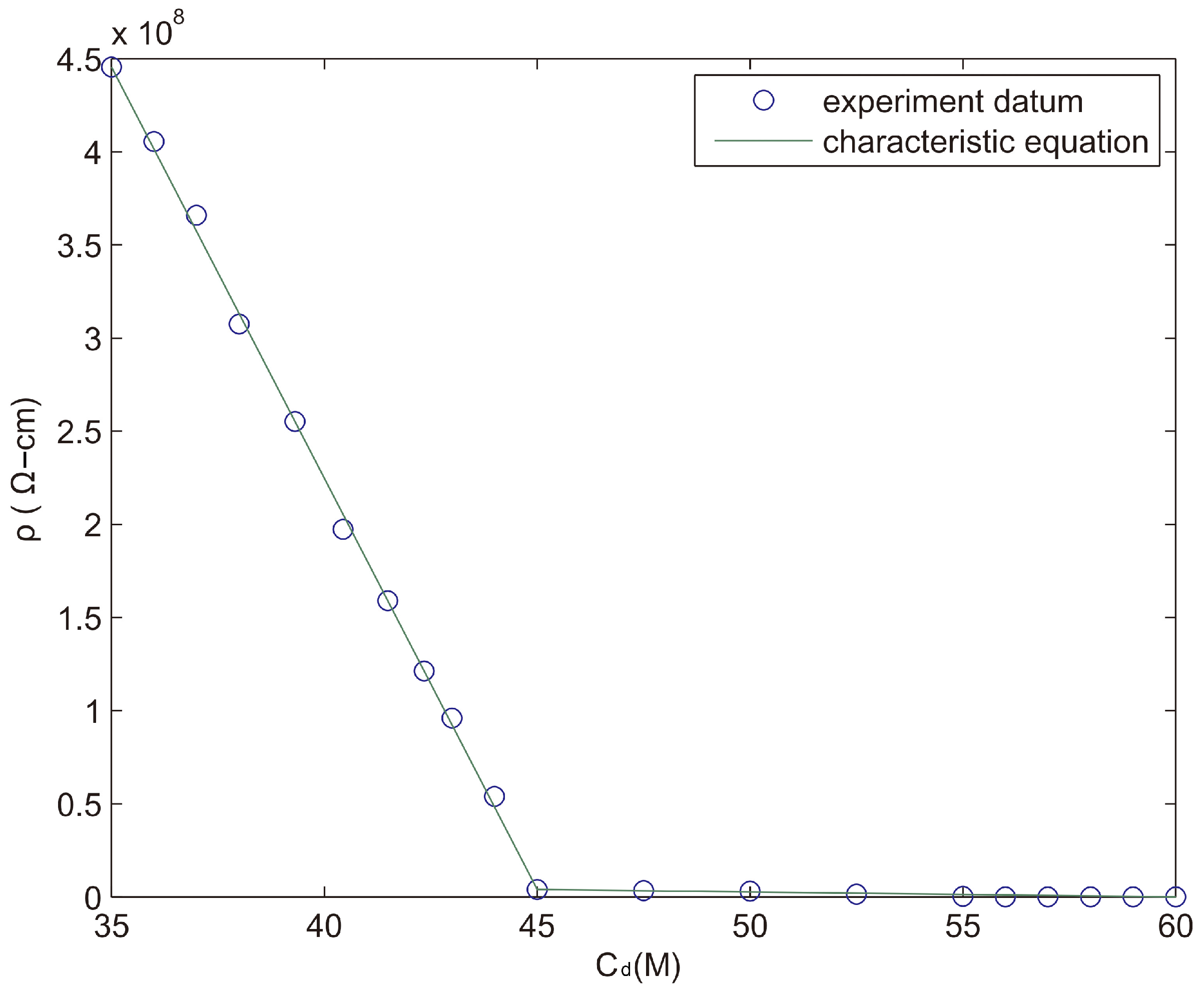
d) and resistivity (ρ) of the specimen is shown in
Figure 11. The specimen’s resistivity and doping concentration are in inverse proportion. At a temperature of 300 K, when the activated carbon doping concentration reaches 35 M, the electric conductivity increases rapidly, but when the activated carbon doping concentration increases to 45 M, the electric conductivity enters into a steady state. In the meanwhile, if the activated carbon doping concentration reaches 55 M, the adsorption of activated carbon is so strong that it causes the specimen’s elasticity to reduce. Moreover, when the activated carbon doping concentration is 60 M, at which point adsorptive saturation is reached, many cracks are left on the surface of the hardened specimen. Increasing to 65 M causes adsorption over-saturation, and the activated carbon desorbs from the surface of the specimen. After many experiments, the equation for the resistance characteristic of the activated carbon doping concentration is derived as follows:
In Formula (2), C0 is the minimum doping concentration required for the elastic polymer composite materials to become resistance materials; ρ0 is the resistivity of C0; Cc is the critical doping concentration at which the conductor is in a steady state; ρc is the resistivity of the critical doping concentration; Cs is the adsorption-saturated doping concentration; and ρs is the resistivity of the adsorption-saturated saturated doping concentration.
At a temperature of 300 K, for the elastic polymer composite materials doped with activated carbon, C0 = 35 M, Cc = 45 M, Cs = 60 M, ρ0 = 4.456 × 10⁸ Ω-cm, ρc = 4 × 10⁶ Ω-cm, and ρs = 1.12 × 10⁴ Ω-cm.
3.2. Graphite’s Characteristic Equation
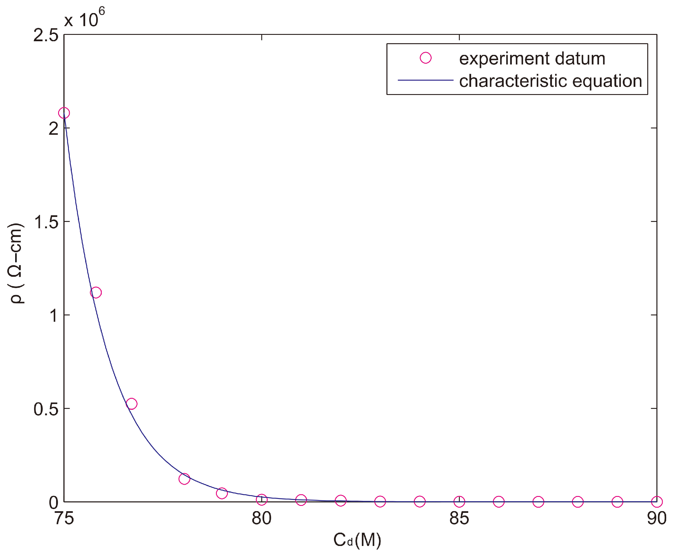
Figure 12 shows the relationship between the graphite doping concentration (C
d) and the resistivity (ρ) of the specimens. When the graphite doping concentration reaches 75 M, the electric conductivity increases sharply; when the graphite doping concentration reaches 79 M, the electric conductivity enters into a steady state; when the graphite doping concentration increases to 90 M, graphite reaches adsorptive saturation and the polymer’s elasticity starts to deteriorate, and as a result, the specimen’s edge has small cracks.
After many experiments, the equation for the resistance characteristic of the graphite doping concentration is derived as follows:
In Formula (3), C0 is the minimum doping concentration required for the elastic polymer composite materials to become resistance materials; ρ0 is the resistivity of C0; Cc is the critical doping concentration at which the conductor is in a steady state; Cs is the adsorption-saturated doping concentration; ρs is the resistivity of the adsorption-saturated doping concentration; and Qm is the quality factor of the material which is dimensionless, where the Qm value of graphite is 4.
At a temperature of 300K, for the elastic polymer composite materials doped with graphite, C
0 = 75 M, C
c = 80 M, C
S = 90 M, ρ
0 = 2.08 × 10
6 Ω-cm, and ρ
s = 3.04 × 10
2 Ω-cm. When C
d is smaller than C
c, Equation (3) could be simplified as follows:
4. Discussion
4.1. Temperature Coefficient of Resistance for Graphite’s Physisorption
Since physisorption occurs without a chemical reaction, it does not need activation energy and can therefore occur easily and at low temperature. The adsorption is an exothermic reaction, so the resistance produced by the elastic polymer composite materials’ physisorption is directly proportional to the temperature. The main force of physisorption is based on the weak van der Waals and easily affected by temperature, so temperature has a great impact on resistance. Conservation of energy dictates that electron transfer between an electrode and a redox system in solution or adsorbed on the electrode surface is fastest when the energy of the electron is equal in the metal and in the thermally activated redox system [
43,
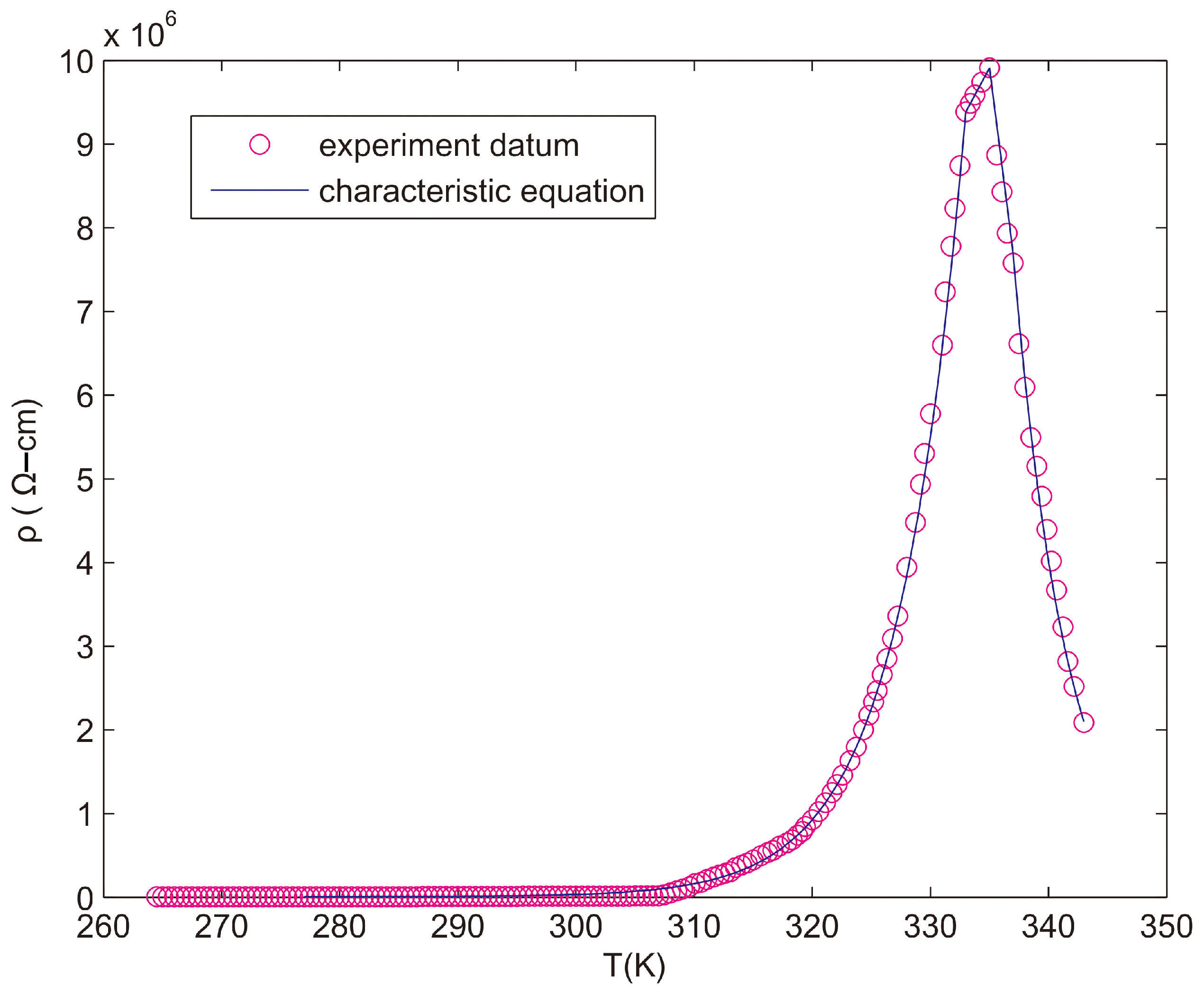
44]. The elastic polymer composite materials were doped with a 46.3 M concentration of graphite, for which the influence of temperature on resistance is shown in
Figure 13. The characteristic equations of resistivity (ρ) and temperature are as follows:
In Formula (5), T0 is the temperature at which absorption starts; ρ0 is the resistivity at temperature T0; Tpl is the initial temperature of the positive temperature coefficient on the linear region; ρpl is the resistivity when the temperature is at Tpl; Tc is the critical temperature of the positive and negative temperature coefficients of the elastic polymer composite materials; ρc is the resistivity when the temperature is at Tc; Tnl is the cut-off temperature of the negative temperature coefficient on the linear region; ρnl is the resistivity when the temperature is at Tnl; Tm is the melting temperature of the elastic polymer composite materials; ρm is the resistivity when the temperature is at Tm; Te is the temperature of the testing environment; and QTd is the thermodynamics characteristic of the material that is dimensionless, and graphite’s QTd is 2. The Dm is the thermal desorption characteristic of the material that is also dimensionless, and graphite’s Dm is 3.
For the elastic polymer composite materials doped with 46.3 M concentration of graphite, T0 = 267 K, Tpl = 312 K, Tc = 319 K, Tnl = 322.5 K, Tm = 343 K, ρ0 = 1.296 × 10³ Ω-cm, ρpl = 4.88 × 10⁴ Ω-cm, ρc = 5.712 × 10⁴ Ω-cm, ρnl = 4.936 × 10⁴ Ω-cm, and ρm = 7.04 × 10³ Ω-cm.
4.2. Temperature Coefficient of Resistance for Activated Carbon’s Physisorption
The influence of temperature on the resistance of the elastic polymer composite materials doped with activated carbon is shown in
Figure 14. The characteristic equation of resistivity and temperature also accords with Formula (5). For the elastic polymer composite materials doped with 45M concentration of activated carbon, Q
Td = 1.3, D
m = 7.7, T
0 = 277 K, T
pl = 333 K, T
c = 335 K, T
nl = 337 K, T
m = 343 K, ρ
0 = 2.856 × 10
6 Ω-cm, ρ
pl = 9.384 × 10
6 Ω-cm, ρ
c = 9.912 × 10
6 Ω-cm, ρ
nl = 7.696 × 10
6 Ω-cm, and ρ
m = 2.088 × 10
6 Ω-cm.
Since ρm is much higher than ρ0, the conductive characteristic of the elastic polymer composite materials is produced by physisorption. When the environmental temperature Te is higher than Tc, the electronic kinetic energy of the valence band increases to cause the energy gap to become smaller. Meanwhile, the resistance temperature characteristics of the elastic polymer composite materials and the semiconductor are the same. Therefore, the resistance temperature coefficient of elastic polymer composite materials has the dual characteristics of metallic conductor and semiconductor.
For the physisorption produced by the elastic polymer composite materials doped with graphite or activated carbon, the resistivity and temperature coefficient characteristics have the same equation, that is, they have the same physical characteristics. However, the surface area of activated carbon is bigger, so the values of the material’s thermodynamics characteristic (QTd) and thermal desorption characteristic (Dm) are different, which makes the resistance temperature characteristic curve of the activated carbon sharper than graphite.
4.3. Application of Elastic Polymer Composite Materials Adsorption of Carbon Powder
Carbon elastic polymer composite materials exhibit a broad range of conductivities due to the diverse types of carbon materials available, allowing them to be utilized in electronic devices. This study leverages the high-surface-area properties of carbon materials to fabricate electronic components from carbon powder. This technology holds promise for widespread use in circuit components and the development of new electronic technologies. Additionally, the extremely low inductance of carbon elastic polymer composites makes them highly suitable for high-frequency circuits [
45,
46].
Carbon black (CB) is a preferred filler in large-scale industrial processes, primarily due to its cost-effectiveness. When added to elastic polymer composite materials, CB can impart electrical conductivity [
47]. These systems exhibit percolation-type conductive behavior [
48,
49,
50], and the introduction of fillers also significantly impacts the mechanical properties, making the material much tougher [
51,
52]. By selecting different fillers and adjusting the required conductivity levels, unique materials can be designed for various applications, including electromagnetic shielding, thermal resistors, automotive boards, power cable shielding, chemical vapor sensors, and pipe applications [
53,
54].
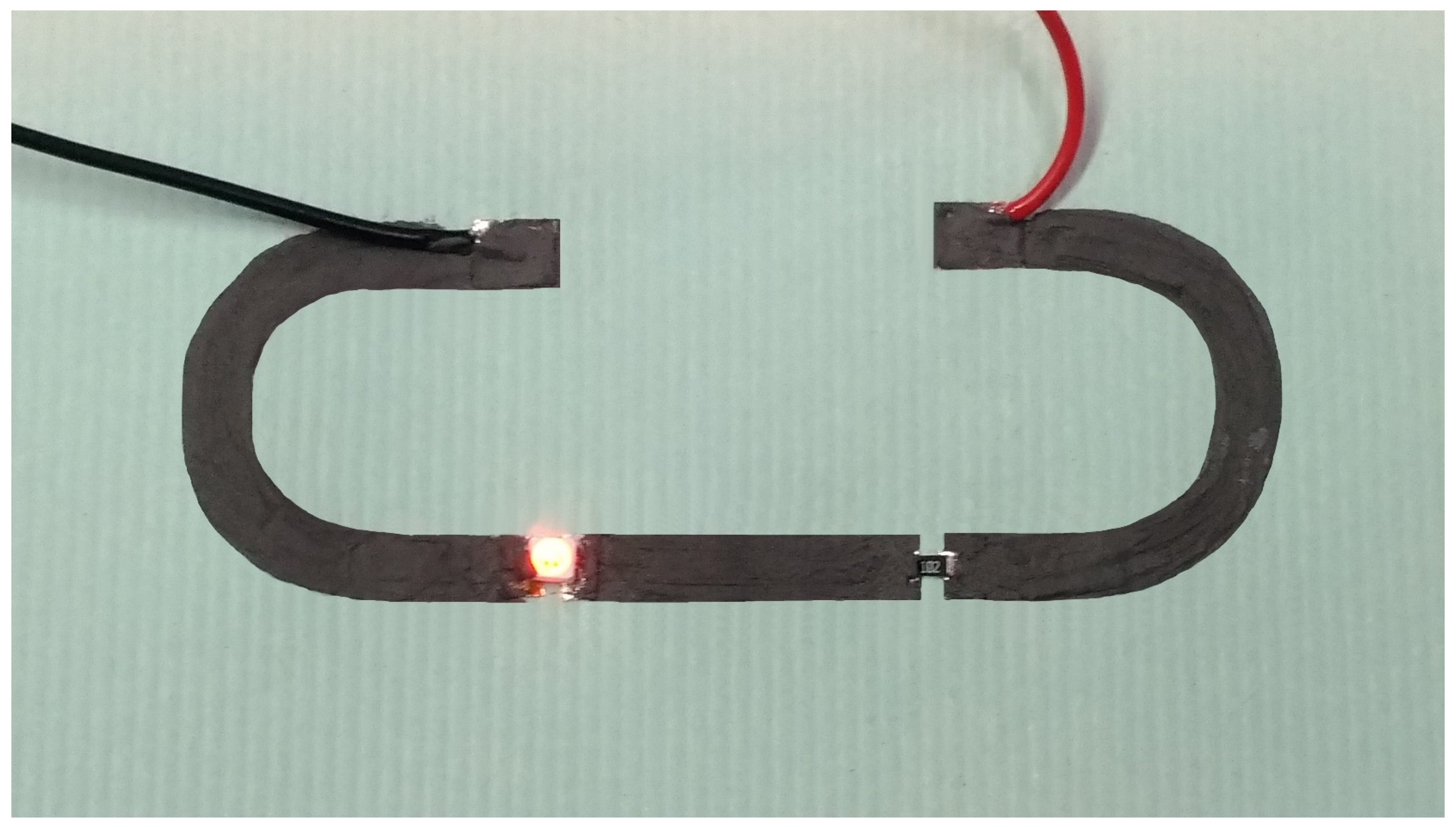
Highly conductive elastic polymer composite materials can be utilized to create both flexible printed circuit boards and traditional printed circuit boards. As illustrated in
Figure 15, the process involves dissolving the material in an organic solvent and then using screen printing to form the conductive circuit. This method eliminates the need for metal materials like copper and avoids waste liquid from corrosion, thus reducing costs and benefiting the environment. These composite materials are also heat-resistant and adaptable to extreme climates, making them suitable for a wide range of applications.
5. Conclusions
This study focuses on the research and development of highly conductive elastic polymer composite materials. These materials are created by doping electrically insulating elastic polymers with high concentrations of activated carbon or graphite particles, which are then dispersed and compounded to form elastic composite conductive polymers. Activated carbon and graphite, both composed of carbon atoms, interact with the rubbery polymeric material through physisorption, altering the molecular packing and reducing the distance between polymer molecules. This results in a high residual force within the polymer molecules.
The performance of organic electronics has seen significant advancements over the past twenty years. Carbon powder allows molecules to stack tightly, reducing the energy gap and imparting semiconductor-like properties to polymers. When combined with solution-processed polymeric materials, such as those used in radio-frequency technologies, this development holds substantial practical value for electronic applications.
However, the electrical conductivity of doped activated carbon and graphite differs significantly. The key distinction lies in how their doping concentration relates to resistivity: in activated carbon, the relationship is linear, while in graphite, it follows an exponential pattern. Consequently, the ratio of surface area to particle size in carbon powder influences its conductive properties. When the surface area is large relative to particle size, the doping concentration and resistivity show a linear relationship. Conversely, if the ratio is low, the relationship becomes exponential. This characteristic is worth further investigation.
Additionally, this study revealed that the physisorption of elastic polymer composite materials is governed solely by van der Waals forces. Unlike covalent bonds, van der Waals forces are weaker and non-selective. While these forces do not form chemical bonds, they do produce a distinct infrared absorption spectrum.
Author Contributions
Conceptualization, T.-H.T. and P.-P.C.; methodology, T.-H.T.; software, P.-P.C.; validation, T.-H.T. and P.-P.C.; formal analysis, T.-H.T.; investigation, P.-P.C.; resources, T.-H.T.; data curation, T.-H.T.; All authors have read and agreed to the published version of the manuscript.
Funding
This research received no external funding.
Institutional Review Board Statement
Not applicable.
Informed Consent Statement
Not applicable.
Data Availability Statement
The original contributions presented in the study are included in the article, further inquiries can be directed to the corresponding author. All the data presented in this study are original.
Conflicts of Interest
The authors declare no conflict of interest.
References
- McCreery, R.L. Advanced carbon electrode materials for molecular electrochemistry. Chem. Rev. 2008, 108, 2646–2687. [Google Scholar] [CrossRef] [PubMed]
- Kinoshita, K. Carbon, Electrochemical and Physicochemical Properties; John Wiley and Sons: New York, NY, USA, 1988. [Google Scholar]
- McCreery, R.L. Electroanalytical Chemistry; Bard, A.J., Ed.; Dekker: New York, NY, USA, 1991; Volume 17. [Google Scholar]
- Leony Leon, C.A.; Radovic, L.R. Chemistry and Physics of Carbon; Thrower, P.A., Ed.; Dekker: New York, NY, USA, 1994; Volume 24. [Google Scholar]
- Zhou, M.; Ding, J.; Guo, L.-p.; Shang, Q.-k. Electrochemical Behavior of l-Cysteine and Its Detection at Ordered Mesoporous Carbon-Modified Glassy Carbon Electrode. Anal. Chem. 2007, 79, 5328–5335. [Google Scholar] [CrossRef]
- Li, H.-Q.; Luo, J.-Y.; Zhou, X.-F.; Yu, C.-Z.; Xia, Y.-Y. An Ordered Mesoporous Carbon with Short Pore Length and Its Electrochemical Performances in Supercapacitor Applications. J. Electrochem. Soc. 2007, 154, A731. [Google Scholar] [CrossRef]
- McDermott, C.A.; McCreery, R.L. Scanning Tunneling Microscopy of Ordered Graphite and Glassy Carbon Surfaces: Electronic Control of Quinone Adsorption. Langmuir 1994, 10, 4307–4314. [Google Scholar] [CrossRef]
- McDermott, M.T.; Kneten, K.; McCreery, R.L. Anthraquinonedisulfonate adsorption, electron-transfer kinetics, and capacitance on ordered graphite electrodes: The important role of surface defects. J. Phys. Chem. 1992, 96, 3124. [Google Scholar] [CrossRef]
- Chaudhury, M.K.; Whitesides, G.M. Direct measurement of interfacial interactions between semispherical lenses and flat sheets of poly (dimethylsiloxane) and their chemical derivatives. Langmuir 1991, 7, 1013. [Google Scholar] [CrossRef]
- Streetman, B.G.; Banerjee, S. Solid State Electronic Devices; Prentice Hall: Saddle River, NJ, USA, 1999; p. 58. [Google Scholar]
- Kokko, K.; Ojala, E.; Mansikka, K. Fermi Level Density of States in Ag—Au Alloys. Nuclear Magnetic Spin-Lattice Relaxation Rate and Low-Temperature Specific Heat. Phys. Status Solidi B 1989, 153, 235–241. [Google Scholar] [CrossRef]
- Kraft, A. Doped Diamond: A Compact Review on a New, Versatile Electrode Material. Int. J. Electrochem. Sci. 2007, 2, 355–385. [Google Scholar] [CrossRef]
- Nesladek, M. Conventional n-type doping in diamond: State of the art and recent progress. Semicond. Sci. Technol. 2005, 20, R19. [Google Scholar] [CrossRef]
- Chatterjee, A.; Compton, R.G.; Foord, J.S.; Hiramatsu, M.; Marken, F. Electrochemical and related processes at surface conductive diamond–solution interfaces. Phys. Stat. Sol. A 2003, 199, 49–55. [Google Scholar] [CrossRef]
- Provent, C.; Haenni, W.; Santoli, E.; Rychen, P. Boron-doped diamond electrodes and microelectrode-arrays for the measurement of sulfate and peroxodisulfate. Electrochim. Acta 2004, 49, 3737–3744. [Google Scholar] [CrossRef]
- Sine, G.; Duo, I.; El Roustom, B.; Foti, G.; Comninellis, C. Deposition of clusters and nanoparticles onto boron-doped diamond electrodes for electrocatalysis. J. Appl. Electrochem. 2006, 36, 847–862. [Google Scholar] [CrossRef]
- Ivandini, T.A.; Sato, R.; Makide, Y.; Fujishima, A.; Einaga, Y. Electroanalytical application of modified diamond electrodes. Diam. Relat. Mater. 2004, 13, 2003–2008. [Google Scholar] [CrossRef]
- Ivandini, T.A.; Sato, R.; Makide, Y.; Fujishima, A.; Einaga, Y. Pt-implanted boron-doped diamond electrodes and the application for electrochemical detection of hydrogen peroxide. Diam. Relat. Mater. 2005, 14, 2133–2138. [Google Scholar] [CrossRef]
- Ivandini, T.A.; Sato, R.; Makide, Y.; Fujishima, A.; Einaga, Y. Electrochemical detection of arsenic(III) using indium-implanted boron-doped diamond electrodes. Anal. Chem. 2006, 78, 6291–6298. [Google Scholar] [CrossRef]
- Xu, J.; Swain, G.M. Oxidation of Azide Anion at Boron-Doped Diamond Thin-Film Electrodes. Anal. Chem. 1998, 70, 1502–1510. [Google Scholar] [CrossRef]
- Granger, M.C.; Xu, J.; Strojek, J.W.; Swain, G.M. Polycrystalline diamond electrodes: Basic properties and applications as amperometric detectors in flow injection analysis and liquid chromatography. Anal. Chim. Acta 1999, 397, 145–161. [Google Scholar] [CrossRef]
- Rao, T.N.; Sarada, B.V.; Tryk, D.A.; Fujishima, A. Electroanalytical study of sulfa drugs at diamond electrodes and their determination by HPLC with amperometric detection. J. Electroanal. Chem. 2000, 491, 175–181. [Google Scholar] [CrossRef]
- Chailapakul, O.; Fujishima, A.; Tipthara, P.; Siriwongchai, H. Electroanalysis of Glutathione and Cephalexin Using the Boron-Doped Diamond Thin-Film Electrode Applied to Flow Injection Analysis. Anal. Sci. 2001, 17, i419. [Google Scholar]
- Witek, M.A.; Swain, G.M. Aliphatic polyamine oxidation response variability and stability at boron-doped diamond thin-film electrodes as studied by flow-injection analysis. Anal. Chim. Acta 2001, 440, 119–129. [Google Scholar] [CrossRef]
- Rao, T.N.; Loo, B.H.; Sarada, B.V.; Terashima, C.; Fujishima, A. Electrochemical detection of carbamate pesticides at conductive diamond electrodes. Anal. Chem. 2002, 74, 1578–1583. [Google Scholar] [CrossRef] [PubMed]
- Wangfuengkanagul, N.; Chailapakul, O. Electrochemical analysis of d-penicillamine using a boron-doped diamond thin film electrode applied to flow injection system. Talanta 2002, 58, 1213–1219. [Google Scholar] [CrossRef] [PubMed]
- Prado, C.; Flechsig, G.-U.; Gründler, P.; Foord, J.S.; Marken, F.; Compton, R.G. Electrochemical analysis of nucleic acids at boron-doped diamond electrodes. Analyst 2002, 127, 329–332. [Google Scholar] [CrossRef]
- Siangproh, W.; Wangfuengkanagul, N.; Chailapakul, O. Electrochemical oxidation of tiopronin at diamond film electrodes and its determination by amperometric flow injection analysis. Anal. Chim. Acta 2003, 499, 183–189. [Google Scholar] [CrossRef]
- Zhang, Y.; Yoshihara, S. Cathodic stripping voltammetry of nickel on boron-doped diamond. J. Electroanal. Chem. 2004, 573, 327–331. [Google Scholar] [CrossRef]
- Chailapakul, O.; Amatatongchai, M.; Wilairat, P.; Grudpan, K.; Nacapricha, D. Flow-injection determination of iodide ion in nuclear emergency tablets, using boron-doped diamond thin film electrode. Talanta 2004, 64, 1253–1258. [Google Scholar] [CrossRef]
- Treetepvijit, S.; Preechaworapun, A.; Praphairaksit, N.; Chuanuwatanakul, S.; Einaga, Y.; Chailapakul, O. Use of nickel implanted boron-doped diamond thin film electrode coupled to HPLC system for the determination of tetracyclines. Talanta 2006, 68, 1329–1335. [Google Scholar] [CrossRef]
- Chang, C.C.; Chen, L.C.; Liu, S.J.; Chang, H.C. The Electro-Oxidation of Formaldehyde at a Boron-Doped Diamond Electrode. Anal. Lett. 2006, 39, 2581–2589. [Google Scholar] [CrossRef]
- Preechaworapun, A.; Chuanuwatanakul, S.; Einaga, Y.; Grudpan, K.; Motomizu, S.; Chailapakul, O. Electroanalysis of sulfonamides by flow injection system/high-performance liquid chromatography coupled with amperometric detection using boron-doped diamond electrode. Talanta 2006, 68, 1726–1731. [Google Scholar] [CrossRef]
- Zhou, Y.L.; Zhi, J.F. Development of an amperometric biosensor based on covalent immobilization of tyrosinase on a boron-doped diamond electrode. Electrochem. Commun. 2006, 8, 1811–1816. [Google Scholar] [CrossRef]
- Ivandini, T.A.; Honda, K.; Rao, T.N.; Fujishima, A.; Einaga, Y. Simultaneous detection of purine and pyrimidine at highly boron-doped diamond electrodes by using liquid chromatography. Talanta 2007, 71, 648–655. [Google Scholar] [CrossRef] [PubMed]
- Sze, S.M. Semiconductor Devices Physics and Technology, 2nd ed.; Wiley: Hoboken, NJ, USA, 2002. [Google Scholar]
- Zhuang, L.; Zhhou, Q.; Lu, J. Simultaneous electrochemical–ESR–conductivity measurements of polyaniline. J. Electroanal. Chem. 2000, 493, 135–140. [Google Scholar] [CrossRef]
- Libert, J.; Coril, J.; dos Santos, D.A.; Brédas, J.L. From neutral oligoanilines to polyanilines: A theoretical investigation of the chain-length dependence of the electronic and optical properties. Phys. Rev. B 1997, 56, 8638. [Google Scholar] [CrossRef]
- Brédas, J.L.; Quattrocchi, C.; Libert, J.; MacDiarmid, A.G.; Ginder, J.M.; Epstein, A. Influence of ring-torsion dimerization on the band gap of aromatic conjugated polymers. J. Phys. Rev. B. 1991, 44, 6002–6010. [Google Scholar] [CrossRef] [PubMed]
- Barta, P.; Kugler, T.; Salaneck, W.R.; Monkman, A.P.; Libert, J.; Lazzzaaroni, R.; Brédas, J.L. Electornic structure of emeraldine and pernigraniline base: A joint theoretical and experimental study. Synth. Met. 1999, 93, 83–87. [Google Scholar] [CrossRef]
- de Oliveira, Z.T.; dos Santos, M.C. Semi-empirical study of chain conformation and absorption spectra of polyanilines: Size, solvent and disorder effects. Chem. Phys. 2000, 260, 95–103. [Google Scholar] [CrossRef]
- Jansen, S.A.; Duong, T.; Major, A.; Wei, Y.; Sein, L.T. Evolution of the electronic states of polyaniline: An ab initio analysis of the orbital states of PAni synthons. Synth. Met. 1999, 105, 107–113. [Google Scholar] [CrossRef]
- Iwasita, T.; Schmickler, W.; Schultze, J.W. The influence of the metal on the kinetics of outer sphere redox reactions. Berichte Bunsenges. Phys. Chem. 1985, 89, 138–142. [Google Scholar] [CrossRef]
- Royea, W.J.; Hamann, T.W.; Brunschwig, B.S.; Lewis, N.S. A Comparison between Interfacial Electron-Transfer Rate Constants at Metallic and Graphite Electrodes. J. Phys. Chem. B 2006, 110, 19433–19442. [Google Scholar] [CrossRef]
- Subramanian, V.; Chang, P.C.; Lee, J.B.; Molesa, S.E.; Volkman, S.K. Printed organic transistors for ultra-low-cost RFID applications. IEEE Trans. Compon. Pack. T 2005, 28, 742–747. [Google Scholar] [CrossRef]
- Yoon, W.-J.; Berger, P.R. Atomic layer deposited HfO2 gate dielectrics for low-voltage operating, high-performance poly-(3-hexythiophene) organic thin-film transistors. Org. Electron. 2010, 11, 1719–1722. [Google Scholar] [CrossRef]
- Medalia, A.I. Electrical conduction in carbon black composites. Rubber. Chem Technol. 1986, 59, 432–454. [Google Scholar] [CrossRef]
- Kirkpartick, S. Percolation and conduction. Rev. Mod. Phys. 1973, 45, 574. [Google Scholar] [CrossRef]
- Lux, F. Models proposed to explain the electrical conductivity of mixtures made of conductive and insulating materials. J. Mater Sci. 1993, 28, 285–301. [Google Scholar] [CrossRef]
- Zallen, P. The Physics of Amorphous Solids; Wiley: New York, NY, USA, 1983. [Google Scholar]
- Chodak, I.; Omastova, M.; Pionteck, J. Relation between electrical and mechanical properties of conducting polymer composites. J. Appl. Polym. Sci. 2001, 82, 1903–1906. [Google Scholar] [CrossRef]
- Xia, J.; Pan, Y.; Shen, L.; Yi, X.S. A model-based approach to electrical percolation behavior of CB-HDPE composites. J. Mater. Sci. 2000, 35, 6145–6150. [Google Scholar] [CrossRef]
- Bigg, D.M.; Stutz, D.E. Plastic Composites for Electromagnetic Interference Shielding Applications. Polym. Compd. 1983, 4, 40–46. [Google Scholar] [CrossRef]
- Lundberg, B.; Sundqvist, B. Resistivity of a composite conducting polymer as a function of temperature, pressure, and environment: Applications as a pressure and gas concentration transducer. J. Appl. Phys. 1986, 60, 1074. [Google Scholar]
| Disclaimer/Publisher’s Note: The statements, opinions and data contained in all publications are solely those of the individual author(s) and contributor(s) and not of MDPI and/or the editor(s). MDPI and/or the editor(s) disclaim responsibility for any injury to people or property resulting from any ideas, methods, instructions or products referred to in the content. |
© 2024 by the authors. Licensee MDPI, Basel, Switzerland. This article is an open access article distributed under the terms and conditions of the Creative Commons Attribution (CC BY) license (https://creativecommons.org/licenses/by/4.0/).


