Article

Transverse and Longitudinal Energy Flows in a Sharp Focus of Vortex and Cylindrical Vector Beams

by
Victor V. Kotlyar
1,2,
Alexey A. Kovalev
1,2,*,
Anton G. Nalimov
1,2,
Sergey S. Stafeev
1,2 and
Alexey M. Telegin
2
1
Image Processing Systems Institute, NRC Kurchatov Institute, Molodogvardeyskaya st., 151, 443001 Samara, Russia
2
Samara National Research University, Moskovskoe sh., 34, 443086 Samara, Russia
*
Author to whom correspondence should be addressed.
Appl. Sci. 2024, 14(14), 6305; https://doi.org/10.3390/app14146305
Submission received: 25 June 2024 / Revised: 15 July 2024 / Accepted: 17 July 2024 / Published: 19 July 2024
(This article belongs to the Section Optics and Lasers)

Abstract

:
It is shown in this work that, with strong focusing of a beam with optical vortex and circular polarization, three energy flows take place in the focal plane: direct longitudinal, reverse longitudinal and azimuthal transverse flows. Calculations are made analytically using the Richards–Wolf formalism and by numerical simulation. Moreover, the energy rotation at different lengths from the optical axis occurs in different directions. Therefore, the focal plane intersects along the optical axis only part of the initial beam energy per unit time. The same energy part (other things being equal) intersects the focal plane along the positive direction of the optical axis when an optical vortex with cylindrical polarization is focused. The difference is that, if an optical vortex is present, then the transverse energy flux at the focus rotates around the optical axis. If an optical vortex is not present (a beam with only cylindrical polarization), then the average transverse flow in the focal plane is zero, though, in some regions in the focal plane, the flow is directed towards the optical axis and, in other regions, away from it. This behavior of the transverse energy flow at the focus (flow direction towards the optical axis and away from the optical axis) of a cylindrical vector beam can be deemed another kind of Hall effect.

1. Introduction

Calculation of the intensity distribution, Poynting vector (energy flow), spin and orbital angular momentum vectors in a sharp focus of laser light is an actual and interesting problem. At the strong focus, all six projections of the electric and magnetic vectors of the electromagnetic beam strength have approximately the same weight and must all be taken into account in the calculations. An adequate analytical description of the behavior of coherent monochromatic light at the focus is provided by the Richards–Wolf theory [1]. Based on this theory, many interesting results have been obtained characterizing the behavior of light in the area of a sharp focus. There are a lot of effects that have been obtained at the focus: spin–orbit conversion [2,3,4,5,6,7], optical (photon) wheels [8,9,10,11], polarized Möbius strips [12,13,14,15,16,17], spin and orbital Hall effects [18,19,20,21], optical magnetization [22,23,24], reverse energy flow [25,26,27,28] and optical skyrmions [29,30,31]. To demonstrate different effects at the focus, laser radiation with different polarization states is used. Light with radial, azimuthal and cylindrical polarization in combination with the vortex phase [32,33] and Poincaré beams [34,35] are used.
In [36,37], we analyzed in detail characteristics of laser beams with circular polarization at a sharp focus. Analytical expressions for projections of an energy flux vector (Umov–Poynting vector), a spin angular momentum (SAM) vector and for a longitudinal projection of the orbital angular momentum (OAM) at the strong focus were obtained. Similar expressions in the strong focus of a vortex beam with cylindrical polarization we obtained in [38]. For different beam types (a circularly polarized optical vortex has a spin, and a vortex with cylindrical polarization has no spin), the same expression for the average energy flow along the optical axis in the focal plane was obtained. This expression shows that only a part of the initial light energy crosses the focal plane in the optical axis direction. It can be assumed that the rest of the energy is directed in the transverse direction. But the energy fluxes averaged over the beam cross section in the focal plane along two transverse Cartesian axes are equal to zero [36,37,38]. A question arises. If only a part of the initial light energy of the beam crosses the focal plane in the longitudinal direction, and there is no energy flow in the transverse direction, what happens with the remaining part of the initial beam energy in the focal plane?
In this work, we show that, in the focal plane, in addition to the forward energy flow, there is a reverse energy flux, or toroidal energy flow, as well as an azimuthal energy flow (energy rotation in a circle), if the initial beam has a vortex (OAM beam), or there is a circular polarization in the initial plane. Calculations are based on the Richards–Wolf formalism and using numerical simulation. If the initial beam with only cylindrical polarization (without a vortex) is considered, then there is no rotating transverse energy flow in the focal plane, but there are two energy flows that compensate each other; one transverse flow propagates towards the optical axis, and the second moves away from the optical axis.

2. Spin and Energy Flows in the Focal Plane for a Circularly Polarized Optical Vortex

Following the works [36,37] for the convenience, we shortly present expressions for the characteristics of the light beam in the focal plane. In the incident plane, the Jones vector of a vortex beam with right-handed circular polarization can be written as follows:
F ( θ , φ ) = B ( θ ) 2 exp ( i m φ ) ( 1 i )
Here, φ is an azimuthal angle in the plane of an exit pupil of an aplanatic optical system. θ is a polar angle, which equals the inclination of light rays to the optical axis, B(θ) is a real function and is an initial beam amplitude, radially symmetrical about the optical axis, and m is an integer topological charge of an optical vortex. Using the Richards–Wolf formalism [1], expressions for all projections of the energy flux vector in the focal plane can be found.
In general, the Poynting vector P is determined by the well-known expression P = c Re ( E * × H ) / ( 2 π ) , where H and E are magnetic and electric field vectors, signs “*” and “×” mean complex conjugate and vector multiplication, Re is a real part of a complex number and c is the vacuum light speed (we will omit later the constant c/(2π)). Projections of the energy flow vector at the focus can be written as follows [36,37]:
P x = Ω ( r ) sin φ , P y = Ω ( r ) cos φ , P z = J 0 , m 2 J 2 , m + 2 2 , Ω ( r ) = J 1 , m + 1 ( J 0 , m + J 2 , m + 2 ) .
Functions Jα,β in (2) denote the following integrals, where the first index is the type of the integral (α = 0, 1, 2), and the second index (β = 0, ±1, ±2, …) equals the Bessel function order Jβ(ξ) under the integral:
J α , β = ( 4 π f λ ) 0 θ 0 sin α + 1 ( θ 2 ) cos 3 α ( θ 2 ) cos 1 / 2 ( θ ) B ( θ ) e i k z cos θ J β ( ξ ) d θ ,
where k = 2π/λ is the wave number, λ is the light wavelength, (r, φ, z) are cylindrical coordinates in focus, f is a focal distance of the aplanatic system and θ0 is the maximal inclination angle of rays to the optical axis, which defines a numerical aperture of the aplanatic lens. The numerical aperture is NA = sin(θ0), ξ = kr sin(θ). Similarly to (2), expressions for the projections of the spin angular momentum (SAM) vector in the focal plane for the initial field (1) can be obtained. The SAM vector is determined by the well-known formula S = Im ( E * × E ) / ( 8 π ω ) , where Im is an imaginary part of a complex number, and ω is an angular frequency of light. Next, we will omit the constant 1/(8πω). In this case, expressions for SAM vector components at the focus of the initial field (1) are completely similar to the Poynting vector components (2):
S x = Ω ( r ) sin φ , S y = Ω ( r ) cos φ , S z = J 0 , m 2 J 2 , m + 2 2 , Ω ( r ) = J 1 , m + 1 ( J 0 , m + J 2 , m + 2 ) .
For the orbital angular momentum (OAM) vector in the focal plane of the field (1), we find a formula only for the longitudinal projection [36]:
L z = Im ( F x * φ F x + F y * φ F y + F z * φ F z ) = m J 0 , n 2 + ( m + 2 ) J 2 , n + 2 2 + 2 ( m + 1 ) J 1 , n + 1 2 .
In (5), Fx, Fy and Fz are projection of the electric field vector F in the focus of the field (1). Let us also write an intensity distribution formula in the focal plane for the initial field (1) [36]:
I ( r , φ , z = 0 ) = | F x | 2 + | F y | 2 + | F z | 2 = J 0 , m 2 + J 2 , m + 2 2 + 2 J 1 , m + 1 2 .
Now let us find the average characteristics of the light field in the focal plane: the energy (or power) of the entire beam I ¯ = W, full longitudinal energy flow P ¯ z , full longitudinal SAM S ¯ z and full longitudinal OAM L ¯ z .
I ¯ = 0 0 2 π I r d r d φ = 0 0 2 π ( J 0 , m 2 + J 2 , m + 2 2 + 2 J 1 , m + 1 2 ) r d r d φ = W 0 + W 2 + 2 W 1 .
P ¯ z = 0 0 2 π P z r d r d φ = 1 2 0 0 2 π r d r d φ ( J 0 , m 2 J 2 , m + 2 2 ) = W 0 W 2 = I ¯ 2 W 2 2 W 1 .
S ¯ z = 0 0 2 π S z r d r d φ = 1 2 0 0 2 π r d r d φ ( J 0 , m 2 J 2 , m + 2 2 ) = W 0 W 2 = I ¯ 2 W 2 2 W 1 .
L ¯ z = 0 r d r 0 2 π d φ L z ( r , φ ) = 0 r d r 0 2 π d φ ( m J 0 , m 2 + ( m + 2 ) J 2 , m + 2 2 + 2 ( m + 1 ) J 1 , m + 1 2 ) = m W 0 + ( m + 2 ) W 2 + 2 ( m + 1 ) W 1 .
Expressions (7)–(10) are obtained based on the following integral from [39]:
W α = 2 π 0 | J α , β ( r ) | 2 r d r = 4 π f 2 0 θ 0 sin 2 α + 1 ( θ 2 ) cos 5 2 α ( θ 2 ) | B ( θ ) | 2 d θ .
It follows from (9) and (10) that the sum of SAM and OAM (angular momentum) is equal to the total energy of the beam I ¯ multiplied by the topological charge m plus 1:
S ¯ z + L ¯ z = ( m + 1 ) I ¯
In order to understand how the average characteristics of the initial field (1) change at the focus, let us find these characteristics in the initial plane:
S ¯ z , 0 =   I ¯ ,   P ¯ z , 0 = I ¯ ,   L ¯ z , 0 = m I ¯ .
From a comparison of (12) and (13), it is seen that the sum of the longitudinal SAM and OAM for the wave (1) is preserved during focusing. The longitudinal SAM at the focus decreases by the amount S ¯ z , 0 S ¯ z   = 2 ( W 2 + W 1 ) relative to the initial value. This decrease is clear; it is due to the spin–orbit conversion effect. Indeed, from a comparison of (10) and (13), it is seen that the magnitude of the longitudinal OAM at the focus increases by exactly the same value: L ¯ z L ¯ z , 0   = 2 ( W 2 + W 1 ) . It is not yet clear why the longitudinal energy flow decreases by the same number of times, as follows from comparison of (8) and (13): P ¯ z , 0 P ¯ z   = 2 ( W 2 + W 1 ) . On the one hand, a part of the beam energy being in the initial plane at all, directed along the optical axis in the focal plane, is clear to propagate not only along it, but also in the transverse direction. However, if we average the crosscut projections of the energy flow vector (2) over the entire focal plane, we obtain zeros:
P ¯ x = 0 0 2 π P x r d r d φ = 0 0 2 π Ω ( r ) sin φ r d r d φ = 0 , P ¯ y = 0 0 2 π P y r d r d φ = 0 0 2 π Ω ( r ) cos φ r d r d φ = 0 .
Integrals in (14) are equal to zero since integrals of sin φ and cos φ over the azimuthal angle φ over an integer period are equal to zero. That is, there is a transverse rotation of the energy flow in the focal plane (2), but, on average, the energy flow along the transverse axes is zero. But, although there is no averaged crosscut energy flow in the focal plane, because the energy still rotates along a circular path, the averaged value of the azimuthal rotating energy flow is nonzero and should be equal to the following expression:
P ¯ φ = 0 0 2 π P φ r d r d φ = 0 0 2 π Ω ( r ) r d r d φ .
It is interesting that, when m = 0 (there is no optical vortex), the azimuthal energy flux will remain unchanged and will be equal to P φ , m = 0 = Ω ( r ) = J 1 , 1 ( J 0 , 0 + J 2 , 2 ) , and the full azimuthal energy flow (15) will not be changed since it is formed by the spin–orbit conversion. The azimuthal energy flow in the focal plane also has a crosscut SAM; the azimuthal projection of the spin density vector (4) is directed tangentially to any circle in the focal plane with the center lying on the optical axis:
S ¯ φ = 0 0 2 π S φ r d r d φ = 0 0 2 π Ω ( r ) r d r d φ .
That is, for light that rotates in a circle in the focal plane, the polarization vector also rotates in a plane perpendicular to the vector Sφ. If Ω ( r ) > 0 in (4), then the polarization vector rotates counterclockwise. Now we see that the initial longitudinal energy flow at the focus is preserved, but redistributed; a part of it goes to the rotating transverse energy flow:
P ¯ z , 0 = P ¯ z   + 2 ( W 2 + W 1 ) = P ¯ z + P ¯ φ
Note that the total energy flow, which propagates along the optical axis (8), consists of two terms, P ¯ z   = W 0 W 2 . Both terms are positive, and the second is always less than the first [39], but the second term is included in the expression with a minus sign. The physical meaning of this term is that this part of the energy flow propagates along the z axis, but in the opposite direction. That is, the term W2 describes the total reverse energy flow in the focal plane. Thus, in (17), we can distinguish not two, but three terms that have a certain physical meaning:
P ¯ z , 0 = W = P ¯ z + + P ¯ z + P ¯ φ = W 0 W 2 + 2 ( W 2 + W 1 ) .
In (18), P ¯ z + = W 0 ,   P ¯ z = W 2 . It was previously shown for the case of an optical vortex with linear polarization that, with a numerical aperture NA = 0.95, only a half of the initial beam energy intersects the focal plane in the positive direction of the optical axis per unit time [40]. Similarly, the initial longitudinal spin decreases, but does not disappear, and is redistributed so that a part of it changes sign, and a part goes to the azimuthal spin of the transverse rotating energy flow:
S ¯ z , 0 = W = W 0 W 2 + 2 ( W 2 + W 1 ) = S ¯ z + + S ¯ z + S ¯ φ
A part of the light flow in the focal plane has changed its spin sign from positive to negative, S ¯ z = W 2 , because circularly polarized light with right-handed polarization, which propagates in the opposite direction to the optical axis, appears to an observer as left-handedly circularly polarized light. And, along the positive direction of the z axis, only a part of the light with right-handed circular polarization and SAM equal to S ¯ z + = W 0 propagates.
These last three equations, Equations (17)–(19), are the main result of this work. The general picture can be presented as follows. In the initial plane, there is only a longitudinal (axial and forward) energy flow and an axial projection of the SAM (spin). And this longitudinal energy flow and longitudinal spin density are equal to the power (total energy) of the vortex beam with right-handed circular polarization. That is, all photons in the initial plane propagate forward and “rotate” around their axis counterclockwise (the spin is +1), and each photon has angular momentum ( m + 1 ) where is the Planck’s constant. In the focal plane, both the total energy flow and the total SAM of the beam are preserved, but are redistributed so that a part of the energy flux propagates in the opposite direction, a part goes to form transverse rotation of energy in a circle in the beam cross section and a part of the total spin goes to form azimuthal spin of light rotating in the focal plane. Figure 1 schematically shows how the energy flow and spin density are redistributed at the beam focus (1).
The deficiency of the previous arguments is that they are based on Equations (15) and (16), which are not derived strictly and are obtained intuitively. But there is another approach to justify the decrease in the longitudinal energy flux in the focal plane. It is based on exact formulas for projections of the electric and magnetic field strength vectors at a sharp focus for the initial field (1):
F x , m = i m 1 2 e i m φ ( J 0 , m + e 2 i φ J 2 , m + 2 ) , F y , m = i m 2 e i m φ ( J 0 , m e 2 i φ J 2 , m + 2 ) , F z , m = 2 i m e i ( m + 1 ) φ J 1 , m + 1 , H x , m = i m 2 e i m φ ( J 0 , m + e 2 i φ J 2 , m + 2 ) , H y , m = i m 1 2 e i m φ ( J 0 , m e 2 i φ J 2 , m + 2 ) , H z , m = 2 i m + 1 e i ( m + 1 ) φ J 1 , m + 1 .
When the initial optical vortex exp(imφ) propagates through a spherical lens, two additional optical vortices, exp(i(m + 2)φ) and exp(i(m + 1)φ), are seen from Equation (20) to be formed, where the expressions of (20) describe field components in the focus of the beam (1). That is, a part of the energy goes to the formation of these vortices. The last optical vortex has only longitudinal projections of the electric and magnetic fields Fz,m and Hz,m, and therefore propagates along the focal plane and does not cross it. The power of this vortex is 2W1, as follows from (11). Another beam with angular harmonic exp(i(m + 2)φ) is described by transverse field projections (20), but we can notice that it is included in the Fx field with a plus sign and in Hy with a minus sign. This optical vortex must propagate along the z axis so that the triple of vectors Fx, Hy and kz is right. But, since the OAM harmonic exp(i(m + 2)φ) enters Hy with a minus sign, then kz < 0 for it, that is, this beam intersects the focal plane in the backward direction. Therefore, the power 2W2 in (8) is subtracted from the total beam power W. It turns out that the total longitudinal energy flow in the focal plane equals, as in (8), P ¯ z = W 2 W 2 2 W 1 . Or, in other words, the longitudinal energy flux in the focal plane is equal to the direct energy flux, which is determined by the energy optical vortex exp(imφ), minus the reverse energy flow, which is determined by the energy of the optical vortex exp(i(m + 2)φ): P ¯ z = W 0 W 2 .

3. Spin and Energy Flow in the Focal Plane for an Optical Vortex with Cylindrical Polarization

In this section, we show that a similar redistribution of energy and spin fluxes at the focus also occurs for another initial light field, namely, an n-order cylindrical vector beam, and with an embedded vortex beam with a topological charge m. The Jones vector in the initial plane for a cylindrical vector beam with an optical vortex has the following form:
F m , n ( θ , φ ) = B ( θ ) exp ( i m φ ) ( cos n φ sin n φ ) ,
where angles θ and φ are defined after (1). Projections of the energy flow vector in the focal plane can be written as follows [38]:
P r = 0 , P φ = Ω ( r ) , P z = 1 2 ( J 0 , m + n 2 + J 0 , m n 2 J 2 , m + n 2 2 J 2 , m n + 2 2 ) , Ω ( r ) = J 1 , m + n 1 ( J 0 , m + n + J 2 , m + n 2 ) + J 1 , m n + 1 ( J 0 , m n + J 2 , m n + 2 ) .
It is clear from (22) that there is an azimuthal energy flow in the focal plane of the initial field (21). Moreover, the energy rotates counterclockwise. The expression for the longitudinal component of the energy flow in (22) has terms with a minus sign, that is, at certain radii, the energy flow can be directed in the backward direction (in the negative direction along the z axis). The expression for the SAM vector longitudinal projection in the focal plane can also be found in [38]:
S z = 1 2 [ I 0 , m n 2 I 0 , m + n 2 + I 2 , m + n 2 2 I 2 , m n + 2 2 + 2 ( 1 ) n cos ( 2 ( n 1 ) φ ) ( I 0 , m n I 2 , m + n 2 I 0 , m + n I 2 , m n + 2 ) ] .
It is seen from (23) that, although the field (21) does not have a longitudinal projection of the SAM in the initial plane (it is equal to zero), the longitudinal projection of the SAM in the focal plane is not zero, and changes its sign when the azimuthal angle φ changes. That is, the polarization at each point in the initial plane is linear, although non-uniform. When going around a circle which is centered on the coordinate center, the direction of the vector of polarization makes n full turns. And, in the focal plane, areas with different signs of the longitudinal SAM projection are formed (23). That is, the spin Hall effect takes place. When going along a certain circle which is centered on the optical axis in the focal plane, the longitudinal SAM sign (the spin sign) changes 4(n − 1) times.
The distribution of intensity in the focal plane for the initial beam (21) is as follows:
I = 1 2 ( I 0 , m + n 2 + I 0 , m n 2 + I 2 , m + n 2 2 + I 2 , m n + 2 2 ) + I 1 , m + n 1 2 + I 1 , m n + 1 2 + ( 1 ) n + 1 cos ( 2 ( n 1 ) φ ) ( I 0 , m + n I 2 , m n + 2 + I 0 , m n I 2 , m + n 2 + 2 I 1 , m + n 1 I 1 , m n + 1 ) .
The intensity in the focal plane is seen from (24) not to have circular symmetry, except for in the case of n = 1. Moreover, the intensity distribution (24) has 2(n − 1) side lobes lying on a circle of a certain radius with a center on the optical axis. Next, using (22)–(24), we find the averaged values of the energy (or power) of the entire beam, the total longitudinal energy flux P ¯ z and the total longitudinal SAM S ¯ z :
I ¯ = 0 0 2 π I r d r d φ = 1 2 0 0 2 π ( J 0 , m + n 2 + J 0 , m n 2 + J 2 , m + n 2 2 + J 0 , m n + 2 2 ) r d r d φ + 0 0 2 π ( J 1 , m + n 1 2 + J 1 , m n + 1 2 ) r d r d φ + ( 1 ) n + 1 0 0 2 π cos ( 2 ( n 1 ) φ ) ( J 0 , m + n J 2 , m n + 2 + J 0 , m n J 2 , m + n 2 2 J 1 , m + n 1 J 1 , m n + 1 ) r d r d φ = W 0 + W 2 + 2 W 1 = W .
P ¯ z = 0 0 2 π P z r d r d φ = 1 2 0 0 2 π r d r d φ ( J 0 , m + n 2 + J 0 , m n 2 J 2 , m + n 2 2 J 2 , m n + 2 2 ) = 1 2 ( W 0 + W 0 W 2 W 2 ) = W 0 W 2 = W 2 W 2 2 W 1 .
S ¯ z = 0 0 2 π S z r d r d φ = 1 2 0 0 2 π r d r d φ ( J 0 , m n 2 J 0 , m + n 2 + J 2 , m + n 2 2 J 2 , m n + 2 2 ) + 2 ( 1 ) n 0 0 2 π r d r d φ cos ( 2 ( n 1 ) φ ) ( J 0 , m n J 2 , m + n 2 J 0 , m + n J 2 , m n + 2 ) = 1 2 ( W 0 W 0 + W 2 W 2 ) = 0 .
It is clear from the comparison that expression (25) coincides with (7), and expression (26) coincides with (8). But (27) does not coincide with (9) since field (21) has no spin in the initial plane. It should not be in any other plane, including the plane of focus. The fact that the total beam energies (1) and (21) coincide follows from the fact that the initial amplitudes of both beams are the same, B(θ), and the vortex component exp(imφ) and the polarization distribution (cos φ, sin φ) do not affect the beam energy value. The total longitudinal energy flux of (26) and (8) is the same for both beams (1) and (21) because both beams have the same vortex component exp(imφ). And, although the azimuthal energy flows (2) and (22) for beams (1) and (21) are different, the part of the energy going to the formation of the transverse azimuthal flow is the same and is equal to expression (15). Note that, when m = 0 (there is no optical vortex), the azimuthal projection of the energy flow is zero: P φ = Ω ( r ) = 0 . Therefore, the following question arises: where does the part of the energy flow in (26) go which previously went to the formation of azimuthal transverse rotation of energy (18) at the focus of the beam (1)? In order to deal with this issue, let us write expressions for the projections of the electric field strength in the focal plane of the initial beam (21):
F x = i m + n 1 2 e i ( m + n ) φ ( J 0 , m + n + e 2 i φ J 2 , m + n 2 ) + i m n 1 2 e i ( m n ) φ ( J 0 , m n + e 2 i φ J 2 , m n + 2 ) , F y = i m + n 2 e i ( m + n ) φ ( J 0 , m + n + e 2 i φ J 2 , m + n 2 ) + i m n 2 e i ( m n ) φ ( J 0 , m n e 2 i φ J 2 , m n + 2 ) , F z = i m + n e i ( m + n 1 ) φ J 1 , m + n 1 i m n e i ( m n + 1 ) φ J 1 , m n + 1 .
The initial beam (21), even in the absence of an optical vortex (m = 0) in the focal plane, is seen from (28) to form four new optical vortices, exp(i(n − 2)φ), exp(i(2 − n)φ), exp(i(n − 1)φ) and exp(i(1 − n)φ) with topological charges (n − 2), −(n − 2), (n − 1) and −(n − 1). A part of the light energy is spent on their formation. There is a transverse azimuthal energy flow (15) if m > 0 in the focal plane since P φ = Ω ( r ) 0 . In this case, the initial optical vortex defines the rotation direction of the energy flow (for m > 0, the energy rotation in the focal plane is counterclockwise). And the situation for field (21) is similar to that formed at the focus for field (1). But when m = 0, the azimuthal energy flow disappears: P φ = Ω ( r ) = 0 . Which direction is the transverse flow facing at the focus if it is present before the focus (the beam converges) and after the focus (the beam diverges)? In the focal plane, when m equals 0 and 1, the longitudinal component of the energy flow is shown by numerical simulation to not change, on average (see Section 3). It turns out that the transverse component of the energy flow in the focal plane remains at each point, and, on average over the plane, is equal to zero. This can happen when, in some areas of the focal plane, the beam is still converging, and, in some places, it is already diverging. Or, in other words, optical vortices of orders (n − 1), −(n − 1), (n − 2) and −(n − 2) propagate along the focal plane and partially along the optical axis but in the opposite direction. Thus, at m = 0, when there is only a cylindrical vector beam of order n at the input, four different energy flows are formed in the focal plane: forward W0, reverse W2 and transverse energy flows directed to the optical axis W2 + W1 and from the optical axis W2 + W1. The total energy flow in the initial plane is preserved in the focal plane:
P ¯ z , 0 = W = P ¯ z + + P ¯ z + P ¯ x , y + P ¯ x , y = W 0 W 2 + 2 ( W 2 + W 1 ) .
The polarization in the focal plane for field (21) at m = 0 (no vortex) is distributed in an unusual way, different from the polarization distribution in the focus of the field (1). Since the longitudinal spin density in the focal plane (23) at m = 0 is equal to zero, the SAM vector has only a transverse projection onto the focal plane, and the polarization ellipses centered at each point of the focal plane are perpendicular to this plane. That is, polarization ellipses resemble optical wheels in which the polarization vector rotates in time like wheel spokes. Moreover, at some points, the polarization vector rotates clockwise, and, at other points of the focal plane, rotates counterclockwise.
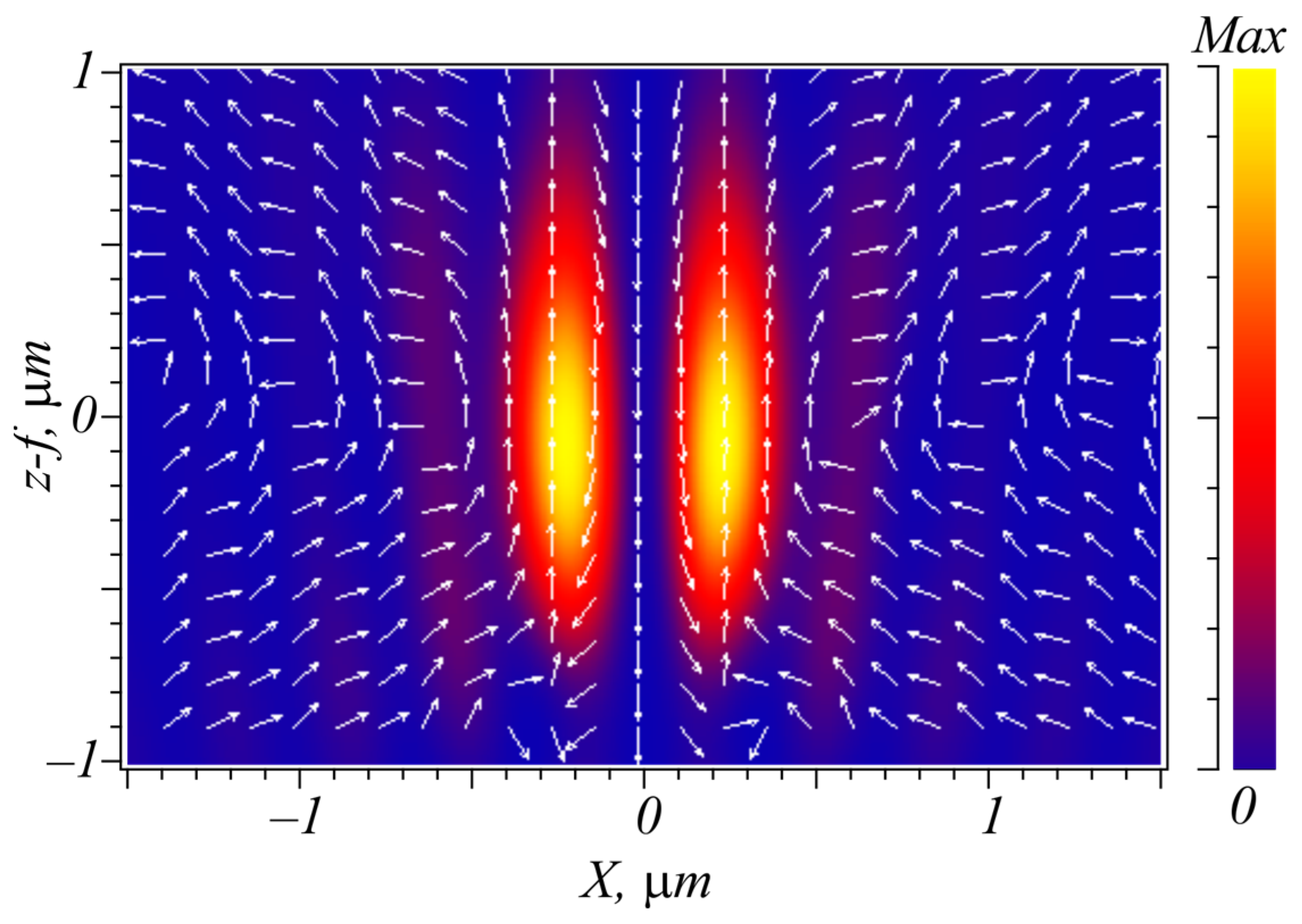
Shown in Figure 2 is a diagram of the wave vector distribution (thick arrows that are perpendicular to the beam cross section) and linear polarization vectors (thin arrows lying in the beam cross section) in the initial plane and in the focal plane for field (21) at m = 0. The initial energy flux, equal to the total beam energy, is seen from Figure 2 to be directed along the optical axis z. This energy flow is divided into four energy flows in the focal plane: a flow along the optical axis z, an energy flow in the opposite direction and two energy flows moving towards each other towards the optical axis and from the optical axis.

4. Simulation

4.1. Energy Flux near the Focus for a Vortex Beam with Right-Handed Circular Polarization

The simulation is carried out using Richards–Wolf integrals [1] of the initial field (1), the wavelength is 633 nm and 0.95 is the numerical aperture.
It is seen from Figure 3 (m = 3) that, before the focal plane (a), the transverse flux is directed towards the coordinate center (the beam converges), after the focal plane (c), the energy flow is directed from the coordinate center (the beam diverges) and, in the focal plane (b), the energy flow rotates along closed trajectories (clockwise and counterclockwise). Blue arrows are also seen in Figure 3 to show the backward energy flux near the focus.
Figure 4 shows that, even at m = 0 (no vortex), the transverse energy flux is directed towards the coordinate center before the focal plane (a), from the optical axis after the focus (b), and, in the focal plane, the transverse energy flux due to the spin–orbital conversion rotates along circular trajectories around the optical axis (b). Moreover, at different distances from the optical axis, the energy flow rotates in different directions. Many blue arrows are seen in Figure 4 to indicate the reverse energy flux directions near the focal spot.
The topological charge in Figure 5 at m = −2 has changed its sign, and, therefore, the energy rotation in the focal plane in the region of maximum intensity is clockwise (b), and not counterclockwise, like in Figure 3. In addition, the energy flow is backward inside the light intensity ring (blue arrows on the optical axis shown in Figure 5). Where the white arrows are, there is only a transverse energy flow and almost no longitudinal.

4.2. Energy Flow near the Focus of a Cylindrical Vector Beam

The simulation results are obtained using the finite difference time domain method of solving the Maxwell’s equations (FDTD method). Simulation parameters are as follows: λ = 633 nm, simulation grid along all three axes is λ/30, the incident field size is 8 × 8 µm, the focal length is f = 1.31 µm (NA = 0.95), the aperture of the incident field is 8 µm (the radius is 4 µm). Arrows in the figures below indicate the direction of the Poynting vector, and the arrow’s length is proportional to the magnitude of it. The arrows are constructed utilizing projections of the Poynting vector Px, Py in the transverse XY plane, and according to the projections Px, Pz in the longitudinal plane XZ. The background (halftones) is an intensity of the electric vector |F|2 (all three projections of the light field are taken into account). Figure 6 shows the transverse Poynting vector distribution near the focus (at a distance of 1 wavelength from the focal plane) for the initial field:
E = ( cos n φ sin n φ ) exp ( i ( m φ k l ) ) ,   l = x 2 + y 2 + f 2 ,   k = 2 π / λ .
Before the focus, the transverse energy flow is seen from Figure 6 to converge to the optical axis (m = 0) (a). After the focus, the transverse energy flow diverges (b) and, almost at the focus itself, partly converges and partly diverges (c). Figure 6d shows the distribution of transverse energy flow in the focal plane: black color—the flow is directed towards the center, white color—from the center. The energy flow in the longitudinal XZ plane before the focus, after the focus and at the focus (e–g) has toroidal form when part of the energy propagates in the opposite direction. Shown in Figure 6g is an enlarged part of the picture in Figure 6e. Figure 6 confirms the prediction of the theory that part of the total initial energy flow W before and after the focus transforms into a transverse energy flow 2(W2 + W1) (light converges at the focus and then diverges). And, at the focus itself, the light converges in some places of the focal plane, and, in some, diverges (c, d). On average, the transverse flow in the focal plane is zero. And part of the energy is directed in the backward direction to the optical axis (reverse or toroidal energy flows). The maximum value of the transverse flow is 4 a.u. before (Figure 6a) and after the focus (Figure 6b), and, at the focus, the maximum value of the transverse flow is almost 10 times less—0.5 a.u. (Figure 6c), though the maximum value of the longitudinal energy flow is 25 a.u. (Figure 6f).
Figure 7 shows the longitudinal intensity and directions of energy flow in the XZ plane, as in Figure 6e, but for the initial field (30) with parameters m = 0, n = 2. The reverse energy flow is seen from Figure 7 to take place near the optical axis. And, in addition, horizontal arrows directed towards the optical axis and away from the optical axis are visible in the focal plane. Both the backward flow and the horizontal arrows shown in Figure 7 prove that not all energy of the initial beam (21), (30) crosses the focal plane. Part of the energy propagates along the surface itself (transverse flow: diverges and converges in different areas), and part in the backward direction to the optical axis.
If there is an optical vortex in the vector field (30), then the energy flows and intensity distribution will have a different form. Figure 8 shows the transverse (a–c) and longitudinal (e) intensity distributions depicted in color as well as profiles of longitudinal projections of the Poynting vector in three observation planes (d). Arrows indicate the direction of the transverse (a–c) and longitudinal (e) Poynting vectors near the focus of the initial field (21) or (30) at m = 1, n = 1. The other parameters are the same as in Figure 6.
Because there is an optical vortex which has a topological charge equal to m = 1, the intensity is seen from Figure 8 to have the form of a transverse ring or longitudinal tube. And the energy flow before the focus not only converges to the optical axis, but rotates around it counterclockwise (Figure 8a). After focus, the transverse energy flux is directed away from the coordinate center (the beam diverges) and still rotates counterclockwise (Figure 8b). At the focus itself, the beam far from the optical axis propagates only along the optical axis, and, near it, the energy flow rotates around the optical axis. The maximum transverse energy flows are different at different distances. Before the focus, the maximum transverse energy flow is 5 a.u. (Figure 8a); after the focus, it is 9 a.u. (Figure 8b); and, at the focus itself, it is 25 a.u. (Figure 8c). The longitudinal energy flux at the focus has a maximum value in the coordinate center and is approximately 45 a.u. Figure 8e shows the intensity in the XZ plane (in color). The arrows indicate the direction of energy flow near the focus.

5. Conclusions

With sharp focusing of an optical vortex with topological charge m and right-handed circular polarization, because of the spin–orbit conversion, a part of the total longitudinal spin Sz equal to the energy 2(W1 + W2), as seen from analytical expressions (7)–(10) obtained in the work, goes into the longitudinal OAM Lz. In this case, the sum of the total longitudinal SAM and OAM is conserved and equal to (m + 1)W, where W is the total energy of the beam. And exactly the same part of the energy 2(W1 + W2) transforms from the total energy flow to the azimuthal energy flow (transverse Poynting vector) at the focus. Although there is some contradiction here, it is believed that the spin of light does not transfer energy [41]. Then how does circularly polarized light (even without an optical vortex) form a focal spot with an azimuthal energy flow in it? In [41], the authors compare the canonical energy flux and the Poynting vector. The Poynting vector can be represented as the sum of two vectors: the orbital flux (canonical energy flux) and the spin flux. The spin flux is a rotor from the spin angular momentum. Since the divergence from the rotor is zero, the spin flux does not participate in the energy transfer, although it does participate in the formation of the electromagnetic field distribution. For example, the presence of a backward energy flow (negative Poynting vector) is simply explained by the fact that the spin flow is negative and greater in magnitude than the orbital flow. When, using a numerical solution (FDTD method) of Maxwell’s equations, we calculate the amplitudes of the magnetic and electric fields in the reverse flow region, the vectors F (electric), H (magnetic) and k (wave vector) form the right-handed triple of vectors if kz < 0. The Poynting vector at a sharp focus is much simpler to calculate than the canonical energy flux. And, therefore, many vector problems at a sharp focus are easier to solve using the Poynting vector. But the main thing is that both energy flows (canonical flow and Poynting vector) satisfy the differential and integral laws of energy conservation. Therefore, the results obtained on their basis are equal if we consider the average characteristics of energy flows when the energy flow crosses closed surfaces. In this work, we considered just such an averaged energy flow intersecting the initial and the focal planes. And it is shown that the total energy flow in the incident plane (longitudinal only) is equal to the total energy flow in the focal plane, if we take into account the reverse energy flow and transverse flow. Note that, without taking into account the reverse flow near the focus, the energy balance cannot be obtained. Let us also note one feature associated with the direction of the energy flow around the optical axis in the focal plane when focusing the optical vortex. It is known that, in scalar vortex beams near the center of the optical vortex, the azimuthal energy flux tends towards infinity as the radial variable tends towards zero (towards the center of the optical vortex) [41]. But, with sharp focusing of a circularly polarized vortex beam (due to the presence of a longitudinal component of the field), the azimuthal energy flux tends towards zero as it approaches the center of the optical vortex. This follows from the comparison of expressions (2) and (6). The azimuthal energy flux in the center (for kr << 1) is proportional to Ω ( r ) ( k r ) 2 m + 1 , and the intensity is proportional to I ( r ) ( k r ) 2 m , so their ratio linearly tends towards zero: Ω ( r ) / I ( r ) ( k r ) .
It is interesting to note that an optical vortex with a topological charge (m + 2), which is present in (20), was experimentally discovered in [4] in the sharp focus of the optical vortex as a result of an increase in the radius of the circular trajectory when the microparticle rotates. This work shows that the radius of the circular trajectory of a microparticle rotation for right-handed circular polarization is greater than for left-handed circular polarization. Since, for the left-handed circular polarization, there is an optical vortex with a topological charge (m − 2) at the focus, the radius of the annular intensity distribution is smaller. Thus, this work makes it possible to theoretically explain the results of the experiment in [4].

Author Contributions

Conceptualization, V.V.K. and A.A.K.; methodology, V.V.K., A.A.K. and S.S.S.; software, A.G.N.; validation, V.V.K., A.A.K., A.G.N., S.S.S. and A.M.T.; formal analysis, V.V.K.; investigation, V.V.K., A.A.K., A.G.N., A.M.T. and S.S.S.; resources, A.G.N., A.M.T. and S.S.S.; data curation, V.V.K.; writing—original draft preparation, V.V.K.; writing—review and editing, V.V.K., A.A.K. and A.G.N.; visualization, A.A.K. and A.G.N.; supervision, V.V.K.; project administration, V.V.K.; funding acquisition, A.G.N. All authors have read and agreed to the published version of the manuscript.

Funding

The work was partly funded by Russian Science Foundation grant #23-12-00236 (the part regarding theory). The work was also carried out within the state assignment of NRC “Kurchatov Institute” (the part regarding simulation).

Institutional Review Board Statement

Not applicable.

Informed Consent Statement

Not applicable.

Data Availability Statement

The original contributions presented in the study are included in the article, further inquiries can be directed to the corresponding author.

Conflicts of Interest

The authors declare no conflicts of interest.

References

  1. Richards, B.; Wolf, E. Electromagnetic Diffraction in Optical Systems. II. Structure of the Image Field in an Aplanatic System. Proc. R. Soc. A Math. Phys. Eng. Sci. 1959, 253, 358–379. [Google Scholar]
  2. Bliokh, K.Y.; Ostrovskaya, E.A.; Alonso, M.A.; Rodríguez-Herrera, O.G.; Lara, D.; Dainty, C. Spin-to-orbital angular momentum conversion in focusing, scattering, and imaging systems. Opt. Express 2011, 19, 26132–26149. [Google Scholar] [CrossRef] [PubMed]
  3. Li, H.; Ma, C.; Wang, J.; Tang, M.; Li, X. Spin-orbit Hall effect in the tight focusing of a radially polarized vortex beam. Opt. Express 2021, 29, 39419–39427. [Google Scholar] [CrossRef] [PubMed]
  4. Arzola, A.V.; Chvátal, L.; Jákl, P.; Zemánek, P. Spin to orbital light momentum conversion visualized by particle trajectory. Sci. Rep. 2019, 9, 4127. [Google Scholar] [CrossRef] [PubMed]
  5. Guo, J.-X.; Wang, W.-Y.; Cheng, T.-Y.; Lü, J.-Q. Interaction of spin-orbit angular momentum in the tight focusing of structured light. Front. Phys. 2022, 10, 1079265. [Google Scholar] [CrossRef]
  6. Wu, Y.; Yu, P.; Liu, Y.; Wang, Z.; Li, Y.; Gong, L. Time-Varying Optical Spin-Orbit Interactions in Tight Focusing of Self-Torqued Beams. J. Light. Technol. 2023, 41, 2252–2258. [Google Scholar] [CrossRef]
  7. Jera, E.S.; Ragb, H.K.; Kyamo, M.J.; Darwish, O.M.; Buaossa, N. Spin-Orbital Angular Momentum Conversion Under High NA Focusing of Vertically Polarized Vortex Beam. In Proceedings of the NAECON 2021—IEEE National Aerospace and Electronics Conference, Dayton, OH, USA, 16–19 August 2021; pp. 150–153. [Google Scholar] [CrossRef]
  8. Graydon, O. Photonic wheel. Nat. Photonics 2013, 7, 672. [Google Scholar] [CrossRef]
  9. Aiello, A.; Banzer, P.; Neugebauer, M.; Leuchs, G. From transverse angular momentum to photonic wheels. Nat. Photonics 2015, 9, 789–795. [Google Scholar] [CrossRef]
  10. Miao, W.; Pang, X.; Liu, W. Photonic Wheels and Their Topological Reaction in a Strongly Focused Amplitude Tailored Beam. IEEE Photonics J. 2020, 12, 6500709. [Google Scholar] [CrossRef]
  11. Berškys, J.; Orlov, S. Interaction of photonic wheel with cluster of nanoparticles. In Proceedings of the 2021 Conference on Lasers and Electro-Optics Europe and European Quantum Electronics Conference, Munich, Germany, 21–25 June 2021. [Google Scholar]
  12. Galvez, E.J.; Dutta, I.; Beach, K.; Zeosky, J.J.; Jones, J.A.; Khajavi, B. Multitwist Möbius Strips and Twisted Ribbons in the Polarization of Paraxial Light Beams. Sci. Rep. 2017, 7, 13653. [Google Scholar] [CrossRef]
  13. Bauer, T.; Banzer, P.; Karimi, E.; Orlov, S.; Rubano, A.; Marrucci, L.; Santamato, E.; Boyd, R.W.; Leuchs, G. Observation of optical polarization Möbius strips. Science 2015, 347, 964–966. [Google Scholar] [CrossRef] [PubMed]
  14. Angelsky, O.V.; Mokhun, I.I.; Bekshaev, A.Y.; Zenkova, C.Y.; Zheng, J. Polarization singularities: Topological and dynamical aspects. Front. Phys. 2023, 11, 1147788. [Google Scholar] [CrossRef]
  15. Wan, C.; Zhan, Q. Generation of exotic optical polarization Möbius strips. Opt. Express 2019, 27, 11516–11524. [Google Scholar] [CrossRef] [PubMed]
  16. Bliokh, K.Y.; Alonso, M.A.; Sugic, D.; Perrin, M.; Nori, F.; Brasselet, E. Polarization singularities and Möbius strips in sound and water-surface waves. Phys. Fluids 2021, 33, 077122. [Google Scholar] [CrossRef]
  17. Freund, I. Polarization Möbius strips on elliptical paths in three-dimensional optical fields. Opt. Lett. 2020, 45, 3333–3336. [Google Scholar] [CrossRef] [PubMed]
  18. Shu, W.; Lin, C.; Wu, J.; Chen, S.; Ling, X.; Zhou, X.; Luo, H.; Wen, S. Three-dimensional spin Hall effect of light in tight focusing. Phys. Rev. A 2020, 101, 023819. [Google Scholar] [CrossRef]
  19. Zhang, M.; Ren, H.; Ouyang, X.; Jiang, M.; Lu, Y.; Hu, Y.; Fu, S.; Li, Z.; Chen, Z.; Guan, B.-O.; et al. Nanointerferometric Discrimination of the Spin–Orbit Hall Effect. ACS Photonics 2021, 8, 1169–1174. [Google Scholar] [CrossRef]
  20. Wang, W.; Zhao, R.; Kang, Q.; Wang, R.; Liu, X.; Liu, T.; Fan, S.W.; Guo, Z. Photonic spin Hall effect driven broadband multi-focus dielectric metalens. Appl. Opt. 2023, 62, 8159–8167. [Google Scholar] [CrossRef] [PubMed]
  21. Neugebauer, M.; Banzer, P.; Bauer, T.; Lindlein, N.; Aiello, A.; Marquardt, C.; Korger, J.; Leuchs, G. Experimental demonstration of the geometric spin Hall effect of light in highly focused vector beams. In Proceedings of the 2012 Conference on Lasers and Electro-Optics (CLEO), San Jose, CA, USA, 6–11 May 2012; pp. 1–2. [Google Scholar] [CrossRef]
  22. Zhao, K.; Zhang, Z.; Zang, H.; Du, J.; Lu, Y.; Wang, P. Generation of pure longitudinal magnetization focal spot with a triplex metalens. Opt. Lett. 2021, 46, 1896–1899. [Google Scholar] [CrossRef]
  23. Ignatyeva, D.O.; Davies, C.S.; Sylgacheva, D.A.; Tsukamoto, A.; Yoshikawa, H.; Kapralov, P.O.; Kirilyuk, A.; Belotelov, V.I.; Kimel, V.A. Plasmonic layer-selective all-optical switching of magnetization with nanometer resolution. Nat. Commun. 2019, 10, 4786. [Google Scholar] [CrossRef]
  24. Hendriks, F.; Rojas-Lopez, R.R.; Koopmans, B.; Guimarães, M.H.D. Electric control of optically-induced magnetization dynamics in a van der Waals ferromagnetic semiconductor. Nat. Commun. 2024, 15, 1298. [Google Scholar] [CrossRef] [PubMed]
  25. Zhou, J.; Ma, H.; Zhang, Y.; Zhang, S.; Min, C.; Yuan, X. Energy flow inversion in an intensity-invariant focusing field. Opt. Lett. 2022, 47, 1494–1497. [Google Scholar] [CrossRef] [PubMed]
  26. Yan, W.; Hu, X.; Li, Y.; Chen, R. Energy Backflow in Tightly Focused Fractional Order Vector Vortex Beams with Binary Topological Charges. Photonics 2023, 10, 820. [Google Scholar] [CrossRef]
  27. Li, H.; Wang, C.; Tang, M.; Li, X. Controlled negative energy flow in the focus of a radial polarized optical beam. Opt. Express 2020, 28, 18607–18615. [Google Scholar] [CrossRef] [PubMed]
  28. Mitri, F.G. Reverse propagation and negative angular momentum density flux of an optical nondiffracting nonparaxial fractional Bessel vortex beam of progressive waves. J. Opt. Soc. Am. A 2016, 33, 1661–1667. [Google Scholar] [CrossRef]
  29. Shen, Y.; Zhang, Q.; Shi, P.; Du, L.; Yuan, X.; Zayats, A.V. Optical skyrmions and other topological quasiparticles of light. Nat. Photonics 2024, 18, 15–25. [Google Scholar] [CrossRef]
  30. Zeng, Y.; Yu, Y.; Shen, X.; Chen, J.; Zhan, Q. Tightly focused optical skyrmions and merons formed by electric-field vectors with prescribed characteristics. Nanophotonics 2024, 13, 251–261. [Google Scholar] [CrossRef]
  31. Barnett, S.M.; Cisowski, C.M.; McWilliam, A.; Speirits, F.C.; Ye, Z.; Götte, J.B.; Franke-Arnold, S. Optical skyrmions. In Proceedings of the SPIE Nanoscience + Engineering, San Diego, CA, USA, 4 October 2023. [Google Scholar] [CrossRef]
  32. Moh, K.J.; Yuan, X.C.; Bu, J.; Burge, R.E.; Gao, B.Z. Generating radial or azimuthal polarization by axial sampling of circularly polarized vortex beams. Appl. Opt. 2007, 46, 7544–7551. [Google Scholar] [CrossRef] [PubMed]
  33. Zhan, Q. Cylindrical vector beams: From mathematical concepts to applications. Adv. Opt. Photonics 2009, 1, 1–57. [Google Scholar] [CrossRef]
  34. Beckley, A.M.; Brown, T.G.; Alonso, M.A. Full Poincaré beams. Opt. Express 2010, 18, 10777–10785. [Google Scholar] [CrossRef]
  35. Naidoo, D.; Roux, F.S.; Dudley, A.; Litvin, I.; Piccirillo, B.; Marrucci, L.; Forbes, A. Controlled generation of higher-order Poincaré sphere beams from a laser. Nat. Photonics 2016, 10, 327–332. [Google Scholar] [CrossRef]
  36. Kotlyar, V.V.; Kovalev, A.A.; Telegin, A.M. Angular and Orbital Angular Momenta in the Tight Focus of a Circularly Polarized Optical Vortex. Photonics 2023, 10, 160. [Google Scholar] [CrossRef]
  37. Kotlyar, V.V.; Stafeev, S.S.; Zaitsev, V.D.; Telegin, A.M.; Kozlova, E.S. Spin–Orbital Transformation in a Tight Focus of an Optical Vortex with Circular Polarization. Appl. Sci. 2023, 13, 8361. [Google Scholar] [CrossRef]
  38. Kotlyar, V.V.; Stafeev, S.S.; Telegin, A.M. Spin angular momentum at the tight focus of a cylindrical vector beam with an imbedded optical vortex. Optik 2023, 287, 171103. [Google Scholar] [CrossRef]
  39. Kovalev, A.A.; Kotlyar, V.V. Spin Hall Effect of Double-Index Cylindrical Vector Beams in a Tight Focus. Micromachines 2023, 14, 494. [Google Scholar] [CrossRef]
  40. Kotlyar, V.V.; Kovalev, A.A.; Kozlova, E.S.; Telegin, A.M. Hall Effect at the Focus of an Optical Vortex with Linear Polarization. Micromachines 2023, 14, 788. [Google Scholar] [CrossRef]
  41. Ghosh, B.; Daniel, A.; Gorzkowski, B.; Bekshaev, A.Y.; Lapkiewicz, R.; Bliokh, K.Y. Canonical and Poynting currents in propagation and diffraction of structured light: Tutorial. J. Opt. Soc. Am. B 2024, 41, 1276–1289. [Google Scholar] [CrossRef]
Figure 1. The distribution of photons in the incident plane with a spin of +1 (right-handed circular polarization), which all propagate along the optical axis, is schematically shown. In the focal plane, some photons propagate in the opposite direction and have a spin of −1, and some photons rotate along a closed trajectory, creating an azimuthal energy flow and an azimuthal spin flow. In fact, the energy flow and the movement of photons are different things, and, here, we talk about photons for clarity of the picture. Between the initial and the focal planes there is a spherical lens, not shown in the figure.
Applsci 14 06305 g001
Figure 2. Scheme of the location of wave vectors k and linear polarization vectors F in the initial plane (21) at m = 0, as well as the direction of energy flows P ¯ z + ,   P ¯ z ,   P ¯ x , y + ,   P ¯ x , y and the location of polarization ellipses in the focal plane. Polarization ellipses are perpendicular to the focal plane. Between the initial and the focal planes, there is a spherical lens, not shown in the figure.
Applsci 14 06305 g002
Figure 3. Intensity distributions (color) and energy fluxes (arrows) near the sharp focus of an optical vortex with right-handed circular polarization. Here are the simulation parameters: the wavelength is λ = 633 nm, the focal length is f = 10 μm, m = 3 is the vortex order, the numerical aperture is NA = 0.95. An amplitude radial distribution of the focused field is uniform (B(θ) = 1). Transverse planes are z = −λ (before the focus) (a), z = 0 (at the focus) (b) and z = +λ (behind the focus) (c). The red, blue and white colors of the arrows mean, respectively, positive, negative and close-to-zero longitudinal energy flow.
Applsci 14 06305 g003
Figure 4. The same as in Figure 3, but for m = 0. The dotted circles are the boundaries of the zones of positive and negative longitudinal energy flow. Transverse planes are z = −λ (before the focus) (a), z = 0 (at the focus) (b) and z = +λ (behind the focus) (c).
Applsci 14 06305 g004
Figure 5. The same as in Figure 3, but for m = −2. Transverse planes are z = −λ (before the focus) (a), z = 0 (at the focus) (b) and z = +λ (behind the focus) (c).
Applsci 14 06305 g005
Figure 6. Intensity distributions near the focus for the incident field (30) at m = 0, n = 1 in color. Arrows show the energy flow direction in the XY plane (ac) at a distance of f − λ (a), f + λ (b), z = 1.41 μm (c) and in the XZ plane (e,g). Transverse flow in the focus plane (d) and profiles of the Poynting vector longitudinal projections in transverse planes (f).
Applsci 14 06305 g006aApplsci 14 06305 g006b
Figure 7. Intensity distribution in color and direction of energy flow (Poynting vector) in the longitudinal XZ plane (arrows) with the same parameters as before, but for the initial wave (30) with parameters m = 0, n = 2.
Applsci 14 06305 g007
Figure 8. Intensity distribution (in color) and Poynting vector (arrows) near the focus for the initial field (30) with m = 1, n = 1 at a distance f − λ (a), f + λ (b) and z = 1.41 μm (c). Arrows show the direction of transverse flow in the XY plane (ac). Longitudinal flow profiles in the focus (d). Intensity and power flow in the XZ plane (e).
Applsci 14 06305 g008
Disclaimer/Publisher’s Note: The statements, opinions and data contained in all publications are solely those of the individual author(s) and contributor(s) and not of MDPI and/or the editor(s). MDPI and/or the editor(s) disclaim responsibility for any injury to people or property resulting from any ideas, methods, instructions or products referred to in the content.

