Article

Characterization of the Prepared CaO-Based Sorbents for Hydrogen Production through Ethanol Steam Reforming

1
National Energy Research Centre, Ministry of Higher Education, Khartoum 4032, Sudan
2
Department of Systems Engineering, Military Technological College, Muscat 111, Oman
3
Jacobs Engineering UK Ltd., Cottons Lane, London SE1 2QG, UK
4
Hydrogen Research Group, University of Nottingham, Nottingham NG7 2RD, UK
*
Authors to whom correspondence should be addressed.
Appl. Sci. 2024, 14(14), 6304; https://doi.org/10.3390/app14146304
Submission received: 26 May 2024 / Revised: 13 July 2024 / Accepted: 15 July 2024 / Published: 19 July 2024
(This article belongs to the Section Materials Science and Engineering)

Abstract

Sorbents for CO2 capture based on CaO have been synthesized and tested for sorption-enhanced steam reforming (SESR) via the co-precipitation method. Various stoichiometries of MgO and CeO2 have been utilized along with Cao and an optimum stoichiometry was identified providing the highest capacity and stability over cycling. The as-synthesized sorbents were structurally characterized by means of XRD and SEM. The thermal characterization was obtained via TGA. The porosity of the synthesized samples was measured by the N2 adsorption and mercury porosimetry. Based on the outcomes of the current work, the sorbents with the highest capacities presented a highly porous structure with a porosity level higher than 65%. The sorbents were tested at high temperatures over repeated cycling (carbonation/decarbonation) to identify the stability of the synthesized sorbents over cycling. The results showed that the stoichiometry of 6:2:1 (CaO, MgO, CeO2) could retain a capacity up to 25 wt% even after 45 cycles.

1. Introduction

Hydrogen as an alternative energy carrier has attracted much attention recently due to its high calorific value and non-polluting combustion, which produces water as a reaction product [1,2]. About 80–85% of global hydrogen is produced from fossil fuels like natural gas and liquid hydrocarbons through three different processes: steam reforming (SR), partial oxidation (POX), and autothermal reforming (ATR) [3,4]. These processes can contribute to the increase in annual global carbon emissions. Since carbon dioxide is produced as a by-product, the CO2 should be captured to ensure a sustainable (zero-emission) process and to prevent its negative economic and environmental impact [5,6]. The Paris Agreement on climate change emphasizes the crucial need to limit the temperature increase to 1.5 °C above pre-industrial levels. Hydrogen and its derivatives will contribute 10% of total emissions reduction by 2050. Fossil fuel-based hydrogen production is expected to expand from 0.04 Gt/year of captured CO2 currently to 3.4 Gt/year of CO2 in 2050 [7]. In the Paris Agreement 1.5 °C scenario, green and blue hydrogen production grows from negligible levels to 19 EJ (154 million tonnes) by 2030 and over 74 EJ (614 million tonnes) by 2050 [8]. Accordingly, the produced hydrogen needs to be low carbon (Blue Hydrogen) or zero carbon (Green Hydrogen), which is produced by water electrolysis using renewable electricity [9]. Clean hydrogen would play an important role in the industrial sector, such as steel production, chemicals, and petrochemicals. Clean hydrogen use is projected to grow to 16 EJ by 2030 and over 38 EJ by 2050. Hydrogen can also play a vital role in balancing renewable electricity supply and demand by offering alternative long-term storage and helping control the variability of energy production across seasons. Hydrogen storage provides long-term seasonal flexibility from 2030 onwards, with an estimated storage capacity of 2000 TWh by 2050 [10]. The choice of suitable CO2 removal sorbents is based on criteria such as capacity, selectivity, adequate adsorption/desorption kinetics, significant stability, low cost, and ease of regeneration [11,12]. The most commonly used sorbent for SESR is calcium oxide (CaO), which can reversibly react with CO2 to form calcium carbonate. Much attention has been given to CaO due to its high CO2 capture capacity and its low cost [13,14]. The deactivation of CaO-based sorbent over multiple cycles of carbonation/decarbonation reactions is well known in the literature [12,13]. It was reported that the CO2 adsorption capacity of natural CaO declines by 80% after a few cycles (10–20 cycles) [15]. CaO sintering and particle agglomeration were suggested to be the main causes of this dramatic drop. Sintering of the sorbents usually occurs at high regeneration temperatures and causes irreversible physical changes, such as the loss of the porous structure [12].
In the current work, novel synthetic CaO-based sorbents for carbon dioxide (CO2) capture in sorption-enhanced steam reforming (SESR) were prepared by the co-precipitation method. Magnesium oxide (MgO) and cerium oxide (CeO2) were added to calcium oxide (CaO) in different molar percentages to obtain the optimum percentage for achieving high and efficient CO2 uptake capacity and cyclic stability. The prepared samples were structurally characterized by X-ray powder diffraction (XRD), scanning electron microscopy (SEM), and energy-dispersive X-ray spectroscopy (EDX). The thermal behavior and calcination temperature were obtained by thermogravimetric analysis (TGA) and the surface area by N2 adsorption analysis. Finally, the performance of the materials was studied and evaluated by multi-cycle carbonization/decarbonization test.

2. Experimental Section

2.1. Materials

Calcium nitrate tetrahydrate Ca(NO3)2·4H2O (≥99.0% purity, Sigma-Aldrich, UK), magnesium nitrate hexahydrate Mg(NO3)2·6H2O (98.0–102.0% (KT) purity, Puriss. p.a., ACS reagent, Sigma-Aldrich) and cerium (III) nitrate hexahydrate Ce(NO3)3·6H2O (99% trace metals basis, Aldrich) were dissolved in a mixture of isopropyl alcohol (IPA) (≥99.7% purity, Sigma-Aldrich) and distilled water at room temperature.

2.2. Sorbents Preparation

Several CaxMgyCez samples were prepared, with the values x, y and z representing the molar percentage of the corresponding oxides loaded in the sample (see Table 1); the resultant solution was stirred for 1 h at 75 °C on a hot plate magnetic stirrer inside a fume cupboard and then evaporated at 350 °C. The procedure followed for the co-precipitation synthesis is described in details in [15].

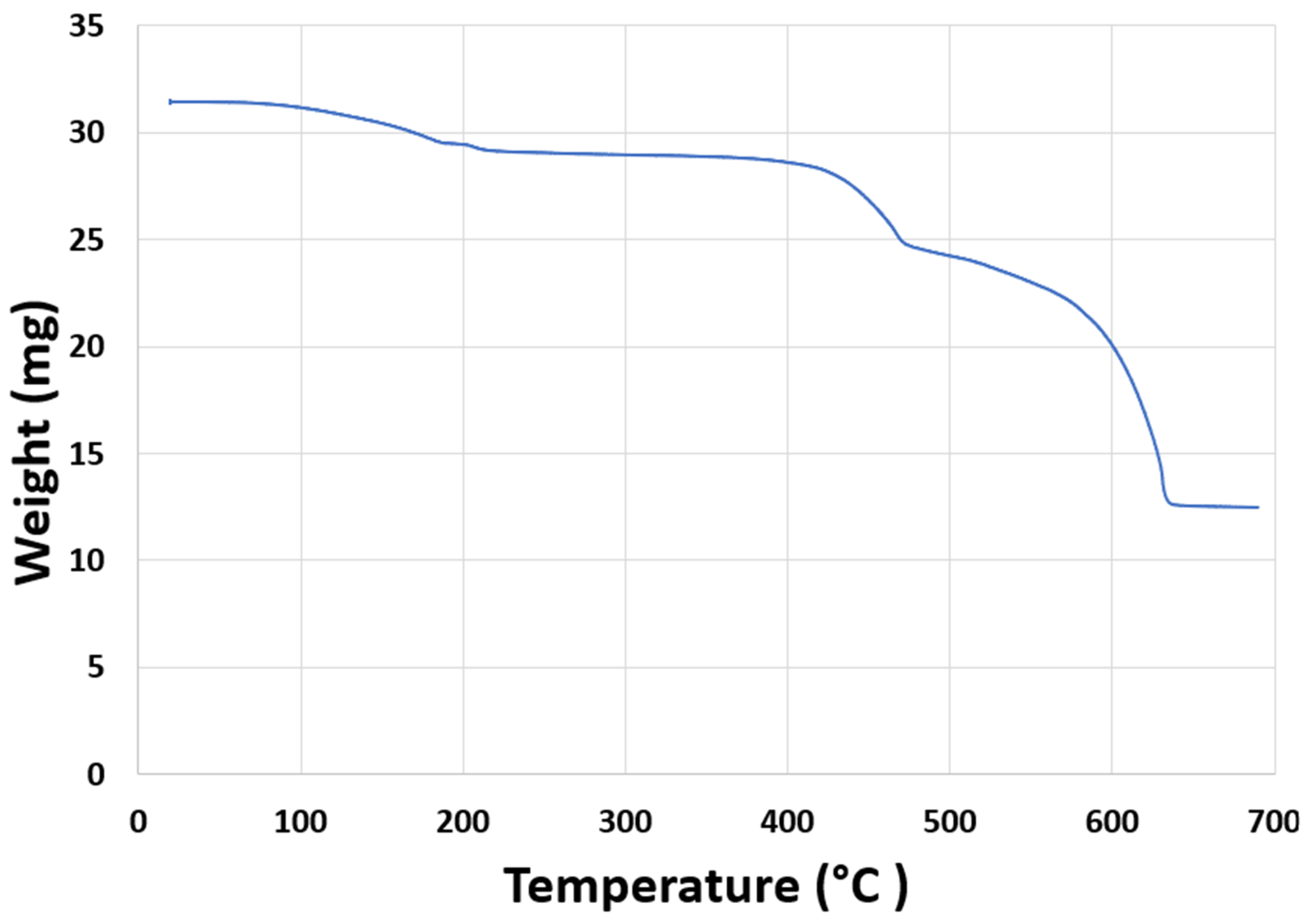
2.3. Determination of the Calcination Temperature

Calcination leads to thermal decomposition, phase transition, and removal of unstable anions and cations that are not desired in the final sorbent. However, the calcination procedure might affect the sorbents’ activity, so an optimum temperature is necessary. To select the optimum temperature for sorbents’ calcination, a thermogravimetric analyzer (TGA) was used. The calcination of samples was carried out using an SDT-Q600-TA instrument, 20–50 mg of sample was heated in an alumina crucible at a heating ramp rate of 20 °C/min from 25 °C up to 800 °C.

2.4. Sorbents Characterization

All samples indicated as being in their fresh state were heated at 750 °C in N2 prior to characterization. This represents the same state inside the reactor at the commencement of reduction on a fresh sample and simulates the heat treatment that all samples received.

2.4.1. X-ray Diffraction (XRD)

XRD patterns were recorded using a Bruker-AXS D8 Advance diffractometer, Karlsruhe, Germany. The samples were scanned at room temperature with Bragg–Brentano geometry, 2θ over a range of 5° to 80°, with a step size of 0.020° and a step time of 2 s. Data were analyzed using Bruker’s Eva software version 3.1.

2.4.2. Scanning Electron Microscopy (SEM)

A Philips XL-30 scanning electron microscope with LaB6 filament, fitted with an Oxford Instruments INCA (High Wycombe, Buckinghamshire, UK), was used to examine surface topography and morphology. Samples were coated with platinum to reduce surface charge.

2.4.3. Surface Area Test (BET)

The surface area of the catalysts/adsorbents was calculated by N2 adsorption/desorption isotherms at −196 °C on a Quantachrome Autosorb-1 Automated Gas Sorption System, using the accompanying software, Autosorb for Windows V1.24, after vacuum degassing overnight at 300 °C.

2.4.4. Porosity Test

Mercury intrusion porosimetry was used to measure pore size and volume. A 0.5–2 g sample was immersed in mercury using the Micromeritics Autopore IV Model 9520, Norcross, GA, USA, which measures a range of pore sizes (0.003 to 360 µm).

2.5. Carbonation Test and Carbonation/De-Carbonation Multi-Cycle Test

About 20–50 mg of the sample was placed in a thermogravimetric analyzer (TGA) (SDT-Q600-TA instrument) for the carbonation/de-carbonation cyclic tests. The sample was heated to 700 °C at a heating rate of 20 °C/min under a nitrogen (N2) atmosphere with a flow rate of 100 mL/min. When the temperature was achieved and stabilized, the carbonation reaction step was conducted. The samples were exposed to 100% carbon dioxide (CO2) at a flow rate of 50 mL/min for 60 min. For the cycling test, N2 gas was purged at a flow rate of 300 mL/min at 700 °C to decarbonate the CO2 sorbent.
The carbonation and decarbonation reactions were carried out at 700 °C. The cycling test was conducted for 25 and 45 cycles of carbonation/decarbonation. The CO2 uptake capacities of sorbents are expressed as the increase in weight percentage, as given in Equation (1).
A d s o r p t i o n / A b s o r p t i o n   c a p a c i t y   ( w % ) = W t W 0 W 0
It can also be defined as molar ratio, as shown in Equation (2).
M o l a r   u p t a k e   c a p a c i t y = M o l e   o f   C O 2   a b s o r b e d / a d s o r b e d M o l e   o f   C a O   i n   s o r b e n t   m i x t u r e
The carbonation conversion α   expressed as
α = ( W 0 W t ) ( W 0 W )
where
  • W 0 : is the initial sorbent weight,
  • W t : is the sorbent weight at time t ,
  • W : is the final weight.

3. Results and Discussion

3.1. Determination of the Calcination Temperature

Calcination is a thermal treatment applied to sorbents or catalysts [16]. It is normally performed in the presence of air at temperatures below the melting point of the catalyst or sorbent. It leads to the modification or stabilization of the mechanical properties of the catalyst or sorbent through phase transition or thermal decomposition. The volatile fraction and the chemically bonded CO2 or water are removed during calcination [12]. It was reported that excessive temperature may lead to catalyst/sorbent sintering. Sintering alters the catalyst/sorbent surface area structure and may affect its activity [17]. Accordingly, an optimum calcination temperature is desired. Thermogravimetric analysis (TGA) was conducted to determine the optimum calcination temperature. Five grams of the sorbent were exposed to air at a 10 °C/min heating rate, ramping from 25 °C to 800 °C. It was observed that the mass loss started at 80 °C and stabilized above 600 °C (see Figure 1).
The mass loss of the sample up to 600 °C was most likely due to dehydration, as the water of crystallization in the sample started to be released at about 400 °C and finished at about 630 °C. This weight loss was due to the thermal decomposition of Ca(OH)2, which decomposes to CaO at 450–500 °C [18]. Similar results were observed from the TGA results and XRD data for the used sorbents as discussed in Section 3.2 and Section 3.3.1 respectively. Accordingly, a calcination temperature of 650 °C for 3 h was applied to all the prepared samples.

3.2. Carbonation Test

The CO2 uptake capacities of all the prepared samples are presented in Table 2. It was observed that, although Ca11Mg2Ce1 and CaO had high calcium weight percentages (72 wt.% and 100 wt.% respectively), their calcium utilizations were low (30 wt.% and 18 wt.% respectively). The Ca1Mg2Ce1 sample had a low calcium percentage uptake capacity, but its calcium utilization was very high at 69%. These results suggest that the high calcium conversion in the sorbent is not related solely to its calcium content but also to its porous structure, as discussed in Section 3.3.3. The thermogravimetric analyzer (TGA), the SDT-Q600-TA instrument, provides a balance sensitivity of 0.1 μg and calorimetric accuracy of ±2%. The CO2 uptake tests were repeated to investigate the accuracy of the results, and the error difference was found to be ±1%.
According to their CO2 uptake capacities, two groups were selected for further characterization and carbonation/de-carbonation cycling tests. The prepared CaO was used as the benchmark. The first group had higher CO2 uptake capacities: Ca6Mg2Ce1 and Ca4Mg2Ce1; the second group had relatively low CO2 uptake capacities: Ca11Mg2Ce1 and Ca1Mg2Ce1 (see Table 2). Ca11Mg2Ce1 had high CaO molar content, whereas Ca1Mg2Ce1 had low CaO molar content (see Table 1). It was observed that the CO2 uptake capacities of Ca4Mg2Ce1 and Ca6Mg2Ce1 were 25 wt.% and 29 wt.%, respectively, and were in the acceptable range for sorption-enhanced steam reforming (SESR) processes, i.e., 20–40 wt.% [15].

3.3. Sorbent Characterization

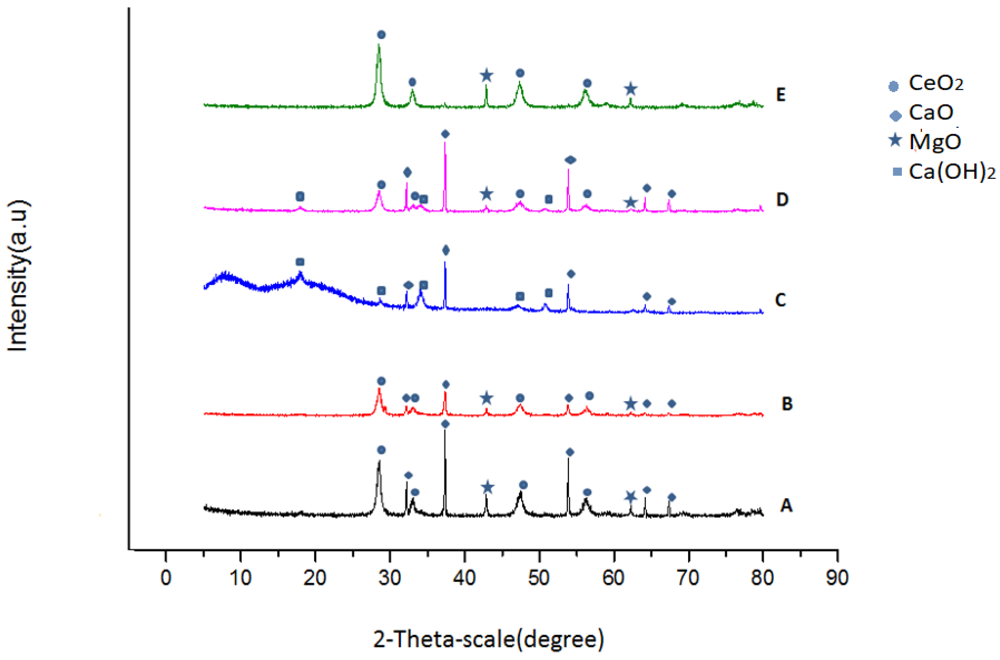
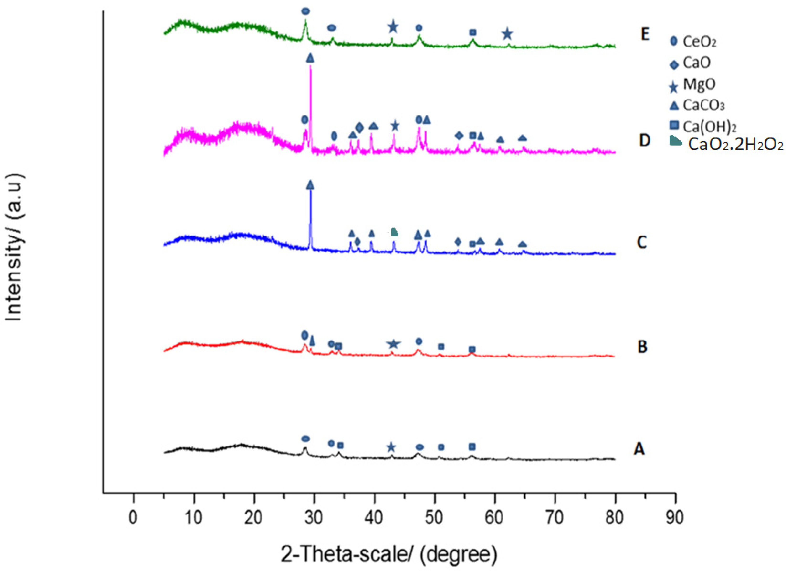
3.3.1. X-ray Diffraction (XRD)

XRD patterns of the selected sorbents were collected to examine the phase changes in the sorbents before and after CO2 uptake, as shown in Figure 2 and Figure 3, respectively. All five fresh samples before CO2 uptake showed similar profiles with three or four peaks corresponding to CaO, MgO, CeO2 and Ca(OH)2, regardless of the weight percentage of the precursor. The appearance of the Ca(OH)2 peak may have been due to moisture contamination of the sample. However, Ca(OH)2 decomposed to CaO at 450–500 °C [14]. Therefore, the presence of Ca(OH)2 in the fresh sample may not have affected the sorbent’s reactivity in the carbonation/decarbonation reactions at 700 °C and in the ethanol sorption-enhanced processes, which were performed at a temperature range of 550–700 °C.
Examination of the CaO d-spacing in all the selected samples indicates that diffraction lines of CaO did not change significantly upon the addition of MgO and CeO2 to the CaO-based sorbents in the different weight percentage as CaO peak observed at 37.5° had d-spacing of (d = 2.40731 nm, d = 2.40633 nm, d = 2.40545 nm, d = 2.40688 nm, d = 2.40427 nm) in Ca4Mg2Ce1, Ca6Mg2Ce1, CaO, Ca11Mg2Ce1 and Ca1Mg2Ce1, respectively, corresponding to the (200) plane with a d-spacing of 2.40587 nm. After CO2 uptake, as shown in Figure 3, three samples yielded patterns of CaCO3. Although CeO2 and MgO could be used for CO2 sorption, their presence in this study was as inert composites. This study investigates the possibility of using CaO doped with MgO and CeO2 as CO2 sorbents to be employed in the ESR process. The experimental investigations of ESR were conducted at temperatures above 550 °C using iron oxide as the catalyst (because the iron oxide reducing temperature was 534 °C). In this temperature range, MgO and CeO2 maintained their inert nature as they did not participate in the carbonation reactions. The absence of magnesium carbonate (MgCO3) in the samples after CO2 uptake confirmed the presence of MgO as a structural support since MgO did not reacts with CO2 at temperatures over 400 °C [15]. On the other hand, the CeO2-based adsorbent exhibited CO2 desorption peak temperatures near 390 K (116.85 °C) [19] and thus, CO2 desorption occurs at a relatively lower temperature than in this study. No appearance of CeCO3 was detected in the XRD samples after CO2 uptake. Nevertheless, employing CeO2 and MgO as CO2 adsorbents has potential for lower-temperature steam reforming processes and could be investigated in further studies. It was also noticed that the CaO phase was detected in all samples after carbonation, except for Ca1Mg2Ce1. This may be due to the low CaO content in this sample, which is only 13% (see Table 3).
The Scherrer equation was used to calculate the crystallite size of CaO, Ca(OH)2, MgO and CeO2. The results are displayed in Table 4.
XRD analysis of the selected samples treated at a calcination temperature of 650 °C revealed that the preparation and calcination procedures were sufficient to convert the nitrate precursor into metal oxides, as no nitrate phases were detected. XRD patterns confirmed that CaO had sharp crystalline peaks. The crystallite size of CaO before CO2 uptake was calculated to be much larger than that of CeO2 and MgO. The dispersion of small grain sizes of CeO2 and MgO between CaO grains may provide a porous surface that favors gas–solid reactions, resulting in high sorbent activity. This observation is consistent with Zhou et al. (2012) [20], who reported that the sorbents with small grains and porous surfaces exhibit high CO2 capture performance.

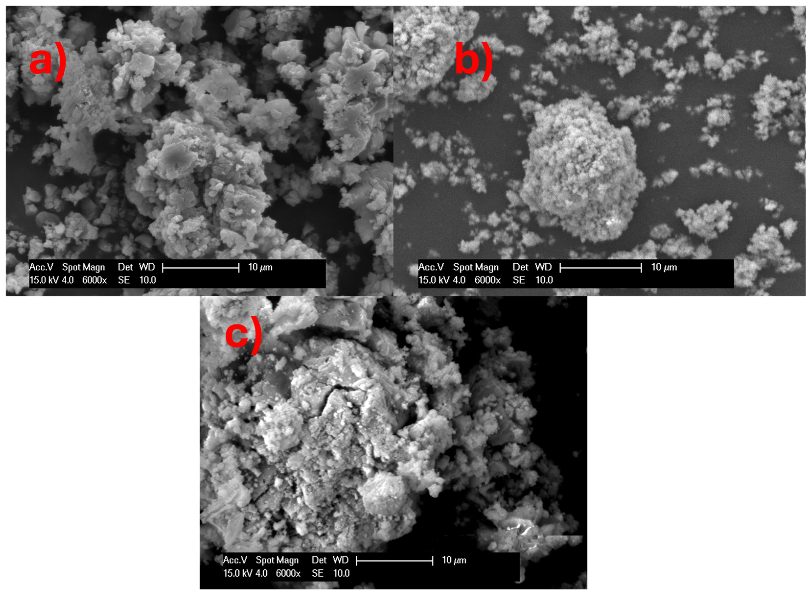
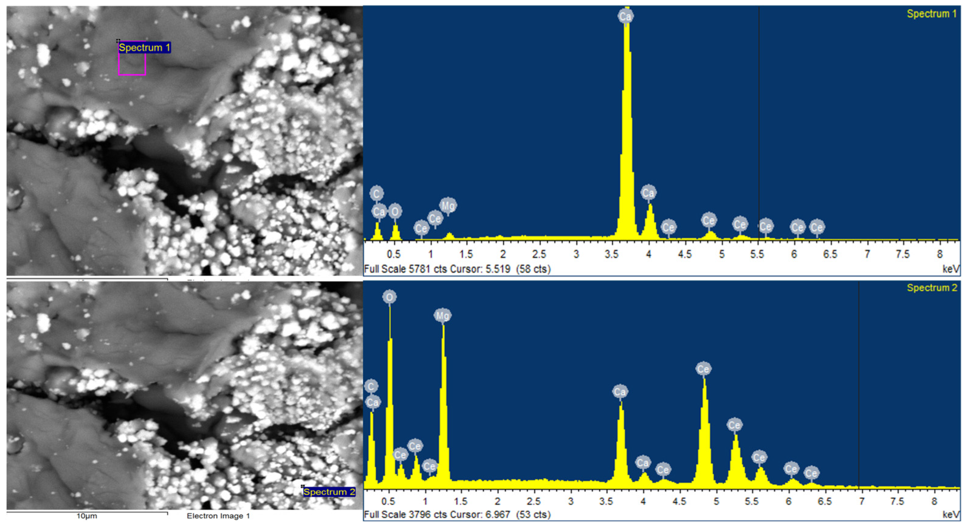
3.3.2. Scanning Electron Microscopy (SEM)

The SEM micrographs obtained from the fresh calcium-based sorbents are shown in Figure 4 and Figure 5. The SEM images of the samples that exhibited higher reactivity, i.e., Ca6Mg2Ce1 and Ca4Mg2Ce1 (see Figure 4), showed significant differences in surface topography compared to those of the poor CO2 uptake group, i.e., Ca11Mg2Ce1, CaO and Ca1Mg2Ce1 (shown in Figure 5). The Ca6Mg2Ce1 and Ca4Mg2Ce1 samples had more porous surfaces and grains of different sizes compared to the group including Ca11Mg2Ce1, CaO and Ca1Mg2Ce1.
The energy-dispersive X-ray (EDX) image, shown in Figure 6, depicts a dark and smooth surface with fewer pores, indicating a calcium-rich area. In contrast, the lighter area with small particle size is the magnesium- and cerium-rich area.
It may be concluded that sorbents with a higher number of small grains and porous surfaces display an initial high CO2 uptake. MgO and CeO2, as inert elements dispersed among CaO particles, separate the CaO particles and provide micro-voids in the sorbent for the CO2 pathway. Additionally, MgO and CeO2, as inert oxides dispersed between the CaO particles, prevent agglomeration and size growth during multiple carbonation/de-carbonation cycles, as previously reported by Ma et al. (2023) [21]. Therefore, it was concluded that the CaO content and the inert percentage in the CaO-based sorbent should be optimized to achieve substantial CO2 uptake capacity and reasonable stability during the carbonation/decarbonation cycles.

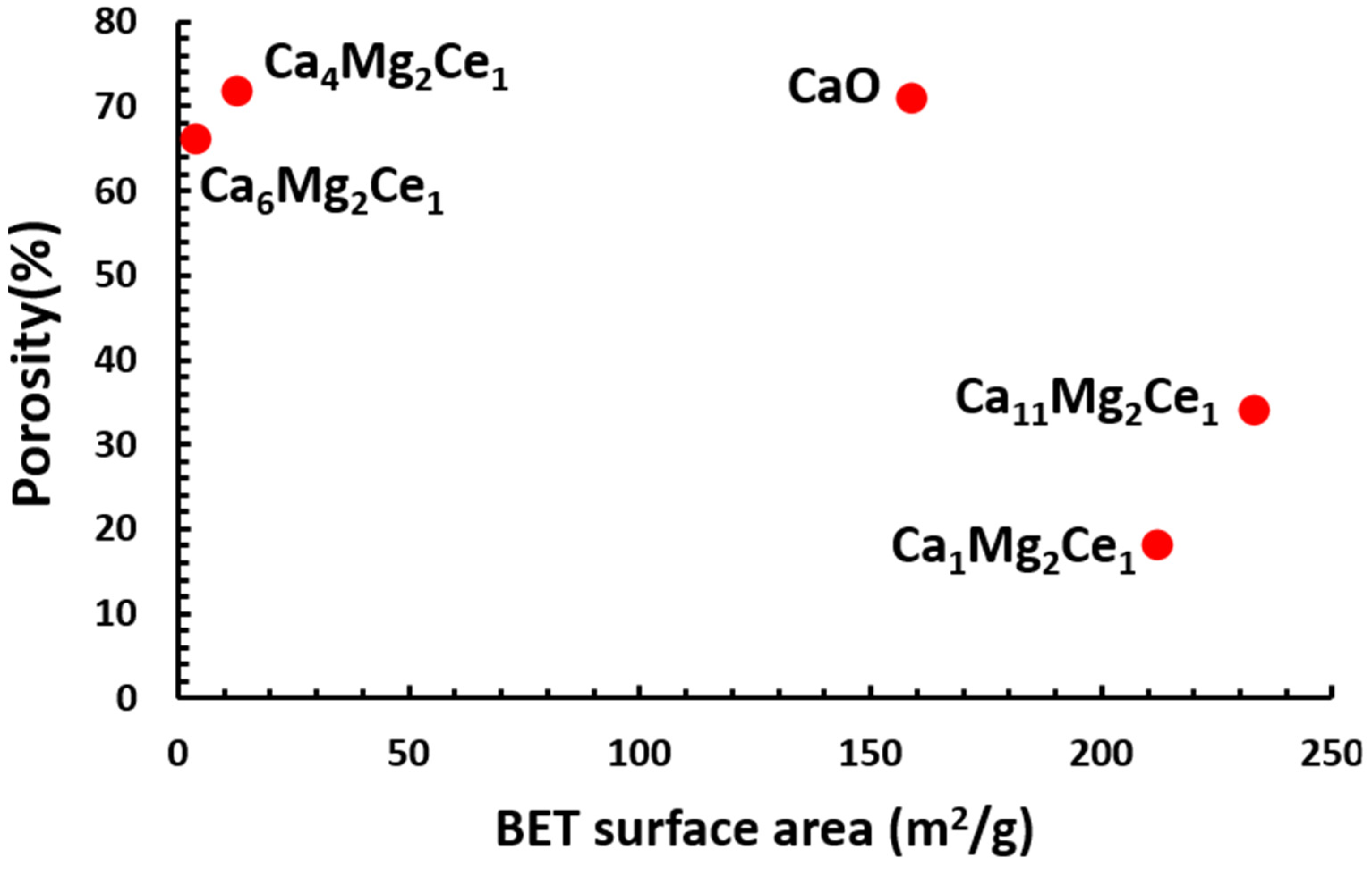
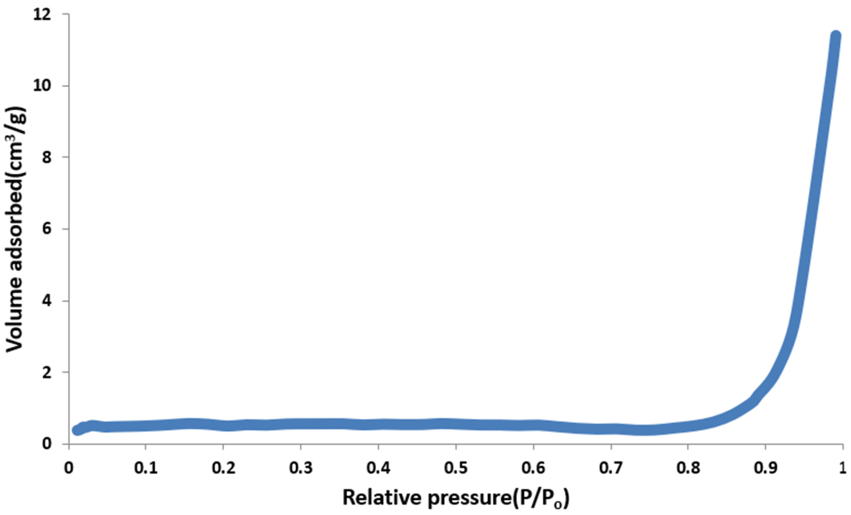
3.3.3. Measurement of Surface Area and Porosity

It is well known that the CO2 uptake capacity and stability of the sorbent reactivity during carbonation/decarbonation cycles are closely related to its micromorphology [12,22]. The CO2 uptake capacity of the sorbents is particularly dependent on the presence of micropores and mesopores in the surface topography. Porosity and pore size distribution for the selected sorbents were evaluated using the Micromeritics Autopore IV Model 9520, which measured a range of pore sizes (0.003–360 µm) at pressures up to 413.6 MPa. Surface area measurements were performed for the selected samples using a Quantachrome Autosorb-1 automated system. Figure 7 clearly shows that the best CO2 uptake groups for the samples before CO2 uptake have higher porosity percentages, substantiating the previous observation from SEM images (see Figure 4 and Figure 5) that high porosity results in higher CO2 uptake. This observation is consistent with Zhou et al. (2012), who reported that sorbents with small grains and porous surfaces exhibit high CO2 capture performance [20]. Moreover, the sorbent stability is closely linked with the pore structure, as discussed in Section 3.4. Similar results were reported by Manovic et al. (2009) [23]. The surface area measurement results shown in Figure 7 reveal no clear correlation between CO2 uptake and large surface area in samples before CO2 uptake. This is contrary to expectations, as a large surface area was anticipated to be the principal factor for higher CO2 uptake capacity. Therefore, a large surface area is not an indicator that sorbents can have good stability over multiple carbonation and calcination cycles. These results are in accordance with Zhang et al.’s (2013) study [24].
It was observed from Figure 8 that nitrogen adsorption started to increase at a relative pressure (p/p0 > 0.8). These results suggest that most of the pores are in the macroporous range.

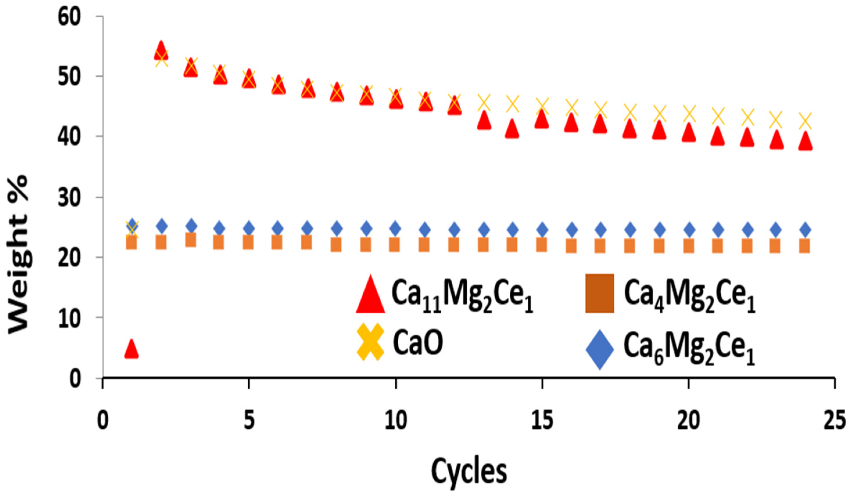
3.4. Sorbent Behavior in Carbonation/De-Carbonation Multi-Cycle Test

The reversibility of carbonation/de-carbonation reactions is limited by the sintering process, which leads to a gradual decay in the sorbent’s CO2 uptake capacity [21]. However, the practical use of the sorbent depends on its reactivity and stability during multiple cycles. In this study, multiple carbonation/calcination cycles were performed in the TGA to investigate changes in the sorbent’s activities upon cycling. TGA was used to investigate the decomposition temperature of CaCO3 and thus determine the optimum decarbonation temperature. The flow rate of CO2 was 50 mL/min for the carbonation reaction, while 30 mL/min of N2 was used for the decarbonation step at 700 °C. The figure shows that purging N2 gas at a flow rate of 300 mL/min at 700 °C was sufficient to level out the CO2 uptake curve and ensure the complete decomposition of CaCO3 back to CaO. Therefore, carbonation and decarbonation reactions were carried out at 700 °C. The data obtained on CO2 uptake capacities over successive carbonation/de-carbonation cycles are shown in Figure 9. It was noted that all samples exhibited an increase in CO2 uptake capacity after the first cycle. Ca11Mg2Ce1 and CaO had a dramatic increase in CO2 uptake capacity after the first cycle. Ca11Mg2Ce1 increased from 17 wt.% to 54 wt.%, whereas CaO increased from 14 wt.% to 53 wt.%. After one cycle, all the selected samples showed a noticeable decline in CO2 uptake capacities but at different rates. After 45 cycles, the overall decay of the CO2 uptake capacities from the capacity of the first cycle was calculated to be 25% for Ca6Mg2Ce1, 29% for Ca4Mg2Ce1 and 39% for CaO
From Figure 9, it was concluded that the stability of CO2 uptake capacity results from small grains and porous surfaces. These results indicate that the addition of MgO and CeO2 helped achieve this stability. The addition of these inerts at certain percentages to CaO can effectively prevent the agglomeration and size growth of CaO during carbonation/decarbonation multi-cycles [22]. However, the CaO content affects the sorbent reactivity. A very high CaO content is not favorable due to the low content of inert material, whereas a low CaO content results in a reduced amount of active CaO and, accordingly, less CO2 uptake capacity. Additionally, doping CaO with Ce and other metal oxides creates more oxygen vacancies in the sorbent to promote the diffusion of CO2 [22,25,26]. The increase in CO2 uptake capacities in all samples after the first cycle indicates a microstructural change following the initial decarbonation reaction. The CO2 released during the decarbonation reaction and changes in surface particle sizes from CaCO3 back to CaO may result in the formation of micro-cracks on the surface, which would facilitate CO2 movement during subsequent carbonation steps and thus increase the CO2 uptake after the first cycle. These results and explanations are similar to those obtained by Zhihong Xu et al. (2021), who referred to this phenomenon as self-deactivation [27]. They explained that during sorbent calcination (high-temperature thermal pretreatment), a hard skeleton was formed. In the next adsorption–desorption cycle, a soft skeleton was generated, which enhanced the sorbent carbonation rate, thereby gradually increasing CO2 adsorption capacity during the initial cycles.

4. Conclusions

Novel synthetic CaO-based sorbents were developed for CO2 capture in the SESR process. Based on the experimental work carried out in this research, the following conclusions were drawn: For the preparation of the CaO-based sorbents, the adapted co-precipitation method from Park, et al 2012 study [15] described in Section 2.1 and Section 2.2, was used adding a drying step at 350 °C with continuous slight stirring inside a fume cupboard. The calcination of the samples at 650 °C successfully converted the nitrate precursors into oxide phases. MgO and CeO2 maintained their inert nature as they did not take part in the carbonation reactions and did not change the crystalline structure of CaO. It has been found that the CO2 uptake capacity and CaO utilization of the prepared samples depend on the MgO, CeO2 and CaO ratio. Thus, controlling this ratio can result in improved CaO utilization and CO2 uptake capacity. It was found that samples with CaO, MgO and CeO2 molar ratios of 6:2:1 and 4:2:1 had CO2 uptake capacities of 29 wt% and 25 wt%, respectively. These values fall within the accepted range of 20–40 wt% for application in SESR processes for CO2 capture [15]. The characterization tests of the prepared samples confirmed that there was no clear correlation between CO2 uptake and surface area. It was also concluded that the presence of MgO and CeO2 as inert composites provided a well-dispersed skeleton (partition wall) that effectively prevented the agglomeration and size growth of CaO. They prevented CaO sorbent sintering and provided a porous surface structure that helps maintain their CO2 uptake capacity during carbonation/decarbonation multi-cycles. Generally, based on the above conclusions, it may be concluded that sorbents’ porous texture is the key parameter for stability over multiple carbonation/decarbonation cycles.

Author Contributions

Conceptualization, E.I.G.; Formal analysis, H.E.; Investigation, M.K.; Resources, G.W.; Writing—original draft, H.E.; Writing—review & editing, M.K.; Supervision, G.W. All authors have read and agreed to the published version of the manuscript.

Funding

This study was financially supported by Islamic Development Bank (IDB) and University of Nottingham (Advanced Material Research Division).

Institutional Review Board Statement

Not applicable.

Informed Consent Statement

Not applicable.

Data Availability Statement

The original contributions presented in the study are included in the article, further inquiries can be directed to the corresponding author.

Conflicts of Interest

Author Evangelos I. Gkanas was employed by the company Jacobs Engineering UK Ltd. The remaining authors declare that the research was conducted in the absence of any commercial or financial relationships that could be construed as a potential conflict of interest.

References

  1. Tan, Y.; Yang, H.; Cheng, J.; Hu, J.; Tian, G.; Yu, X. Preparation of hydrogen from metals and water without CO2 emissions. Int. J. Hydrogen Energy 2022, 47, 38134–38154. [Google Scholar] [CrossRef]
  2. Khzouz, M.; Gkanas, E.I.; Du, S.; Wood, J. Catalytic performance of Ni-Cu/Al2O3 for effective syngas production by methanol steam reforming. Fuel 2018, 232, 672–683. [Google Scholar] [CrossRef]
  3. Sazali, N. Emerging technologies by hydrogen: A review. Int. J. Hydrogen Energy 2020, 45, 18753–18771. [Google Scholar] [CrossRef]
  4. Khzouz, M.; Gkanas, E. Experimental and numerical study of low temperature methane steam reforming for hydrogen production. Catalysts 2017, 8, 5. [Google Scholar] [CrossRef]
  5. Kouchaki-Penchah, H.; Bahn, O.; Bashiri, H.; Bedard, S.; Bernier, E.; Elliot, T.; Hammache, A.; Vaillancourt, K.; Levasseur, A. The role of hydrogen in a net-zero emission economy under alternative policy scenarios. Int. J. Hydrogen Energy 2024, 49, 173–187. [Google Scholar] [CrossRef]
  6. Gkanas, E.I.; Steriotis, T.A.; Stubos, A.K.; Myler, P.; Makridis, S. A complete transport validated model on a zeolite membrane for carbon dioxide permeance and capture. Appl. Therm. Eng. 2015, 74, 36–46. [Google Scholar] [CrossRef]
  7. Khzouz, M.; Gkanas, E.I.; Shao, J.; Sher, F.; Beherskyi, D.; El-Kharouf, A.; Qubeissi, M. Life cycle costing analysis: Tools and applications for determining hydrogen production cost for fuel cell vehicle technology. Energies 2020, 13, 3783. [Google Scholar] [CrossRef]
  8. IRENA. World Energy Transition Outlook, 2022; IRENA: Abu Dhabi, United Arab Emirates, 2022. [Google Scholar]
  9. Khzouz, M.; Gkanas, E.I.; Girella, A.; Statheros, T.; Milanese, C. Sustainable hydrogen production via LiH hydrolysis for unmanned air vehicle (UAV) applications. Int. J. Hydrogen Energy 2020, 45, 5384–5394. [Google Scholar] [CrossRef]
  10. Lyons, M.; Durrant, P.; Kochhar, K. Reaching Zero with Renewables: Capturing Carbon; IRENA: Abu Dhabi, United Arab Emirates, 2021; Volume 108. [Google Scholar]
  11. da Silva, T.H.; Chaghouri, M.; Cesário, M.R.; Tidahy, H.L.; Gennequin, C.; Macedo, D.A.; Abi-Aad, E. The role of CO2 sorbents materials in SESMR for hydrogen production. In Heterogeneous Catalysis; Elsevier: Amsterdam, The Netherlands, 2022; pp. 141–174. [Google Scholar]
  12. Blamey, J.; Anthony, E.; Wang, J.; Fennell, P. The calcium looping cycle for large-scale CO2 capture. Prog. Energy Combust. Sci. 2010, 36, 260–279. [Google Scholar] [CrossRef]
  13. Abanades, J.C.; Anthony, E.J.; Lu, D.Y.; Salvador, C.; Alvarez, D. Capture of CO2 from combustion gases in a fluidized bed of CaO. AIChE J. 2004, 50, 1614–1622. [Google Scholar] [CrossRef]
  14. Dou, B.; Wang, C.; Song, Y.; Chen, H.; Jiang, B.; Yang, M.; Xu, Y. Solid sorbents for in-situ CO2 removal during sorption-enhanced steam reforming process: A review. Renew. Sustain. Energy Rev. 2016, 53, 536–546. [Google Scholar] [CrossRef]
  15. Park, J.; Yi, K. Effects of preparation method on cyclic stability and CO2 absorption capacity of synthetic CaO–MgO absorbent for sorption-enhanced hydrogen production. Int. J. Hydrogen Energy 2012, 37, 95–102. [Google Scholar] [CrossRef]
  16. Katheria, S.; Gupta, A.; Deo, G.; Kunzru, D. Effect of calcination temperature on stability and activity of Ni/MgAl2O4 catalyst for steam reforming of methane at high pressure condition. Int. J. Hydrogen Energy 2016, 41, 14123–14132. [Google Scholar] [CrossRef]
  17. Han, R.; Wang, Y.; Xing, S.; Pang, C.; Hao, Y.; Song, C.; Liu, Q. Progress in reducing calcination reaction temperature of Calcium-Looping CO2 capture technology: A critical review. Chem. Eng. J. 2022, 450, 137952. [Google Scholar] [CrossRef]
  18. Criado, Y.A.; Alonso, M.; Abanades, J. Kinetics of the CaO/Ca(OH)2 hydration/dehydration reaction for thermochemical energy storage applications. Ind. Eng. Chem. Res. 2014, 53, 12594–12601. [Google Scholar] [CrossRef]
  19. Yoshikawa, K.; Kaneeda, M.; Nakamura, H. Development of Novel CeO2-based CO2 adsorbent and analysis on its CO2 adsorption and desorption mechanism. Energy Procedia 2017, 114, 2481–2487. [Google Scholar] [CrossRef]
  20. Zhou, Z.; Qi, Y.; Xie, M.; Cheng, Z.; Yuan, W. Synthesis of CaO-based sorbents through incorporation of alumina/aluminate and their CO2 capture performance. Chem. Eng. Sci. 2012, 74, 172–180. [Google Scholar] [CrossRef]
  21. Ma, K.; Han, L.; Wu, Y.; Rong, N.; Xin, C.; Wang, Z.; Ding, H.; Qi, Z. Synthesis of a composite Fe–CaO-based sorbent/catalyst by mechanical mixing for CO2 capture and H2 production: An examination on CaO carbonation and tar reforming performance. J. Energy Inst. 2023, 109, 101256. [Google Scholar] [CrossRef]
  22. Wang, Y.; Memon, M.Z.; Seelro, M.A.; Fu, W.; Gao, Y.; Dong, Y.; Ji, G. A review of CO2 sorbents for promoting hydrogen production in the sorption-enhanced steam reforming process. Int. J. Hydrogen Energy 2021, 46, 23358–23379. [Google Scholar] [CrossRef]
  23. Manovic, V.; Anthony, E. Long-term behavior of CaO-based pellets supported by calcium aluminate cements in a long series of CO2 capture cycles. Ind. Eng. Chem. Res. 2009, 48, 8906–8912. [Google Scholar] [CrossRef]
  24. Zhang, M.; Peng, Y.; Sun, Y.; Li, P.; Yu, J. Preparation of CaO–Al2O3 sorbent and CO2 capture performance at high temperature. Fuel 2013, 111, 636–642. [Google Scholar] [CrossRef]
  25. Wu, S.; Beum, T.; Yang, J.; Kim, J. Properties of Ca-base CO2 sorbent using Ca(OH)2 as precursor. Ind. Eng. Chem. Res. 2007, 46, 7896–7899. [Google Scholar] [CrossRef]
  26. Heidari, M.; Tahmasebpoor, M.; Mousavi, S.B.; Pevida, C.J. CO2 capture activity of a novel CaO adsorbent stabilized with (ZrO2+ Al2O3+ CeO2)-based additive under mild and realistic calcium looping conditions. J. CO2 Util. 2021, 53, 101747. [Google Scholar] [CrossRef]
  27. Xu, Z.; Jiang, T.; Zhang, H.; Zhao, Y.; Ma, X.; Wang, S. Efficient MgO-doped CaO sorbent pellets for high temperature CO2 capture. Front. Chem. Sci. Eng. 2021, 15, 698–708. [Google Scholar] [CrossRef]
Figure 1. TGA profiles for the determination of the calcination temperature for the Ca6Mg2Ce1 at heating ramp of 10 °C/min from 25 °C to 700 °C in air and at atmospheric pressure.
Applsci 14 06304 g001
Figure 2. XRD patterns of the sorbents before CO2 uptake. (A) Ca6Mg2Ce1 (B) Ca4Mg2Ce1 (C) CaO (D) Ca11Mg2Ce1 and (E) Ca1Mg2Ce1.
Applsci 14 06304 g002
Figure 3. XRD patterns of the sorbents after CO2 uptake. (A) Ca6Mg2Ce1 (B) Ca4Mg2Ce1 (C) CaO (D) Ca11Mg2Ce1 (E) Ca1Mg2Ce1.
Applsci 14 06304 g003
Figure 4. SEM images of (a) Ca6Mg2Ce1 and (b) Ca4Mg2Ce1 and before CO2 uptake.
Applsci 14 06304 g004
Figure 5. SEM images of (a) CaO, (b) Ca11Mg2Ce1 and (c) Ca1Mg2Ce1 before CO2 uptake.
Applsci 14 06304 g005
Figure 6. EDX images of Ca6Mg2Ce1 sample.
Applsci 14 06304 g006
Figure 7. Porosity verses BET surface area results for the prepared sorbents before CO2 uptake.
Applsci 14 06304 g007
Figure 8. Nitrogen adsorption isotherm of Ca6Mg2Ce1 obtained by BET.
Applsci 14 06304 g008
Figure 9. The sorbents’ CO2 uptake capacities in weight percentage over 25 cycles under carbonation conditions (700 °C, 60 min, CO2 flow rate of 50 mL/min) and decarbonation conditions (700 °C, 60 min, N2 flow rate of 350 mL/min).
Applsci 14 06304 g009
Table 1. Sorbents’ molar ratio.
SampleMolar Ratio
Ca4Mg2Ce13.7:1.7:1
Ca6Mg2Ce15.5:1.7:1
Ca3Mg2Ce12.8:1.7:1
Ca2Mg2Ce11.8:1.7:1
Ca1Mg2Ce10.6:1.7:1
Ca7Mg2Ce17.4:1.7:1
Ca11Mg2Ce111.0:1.7:1
Ca3Mg2Ce12.6:1.7: 1
CaO100
Table 2. CO2 uptake capacities for all the prepared sorbents in weight and molar percentage bases.
SampleCO2 Uptake in Weight/%CO2 Uptake in/Molar (*) %
Ca4Mg2Ce12566
Ca6Mg2Ce12966
Ca3Mg2Ce11033
Ca2Mg2Ce11642
Ca1Mg2Ce1769
Ca7Mg2Ce1612
Ca11Mg2Ce11730
CaO1418
(*) mole CO2/mole CaO.
Table 3. CO2 uptake capacities in weight percentage and molar bases of the selected sorbents.
SampleCaO Percentage in Sample
/wt.%
CO2 Uptake by Weight (wt CO2/wt CaxMgyCez)
/wt.%
CO2 Uptake by Weight (wt CO2/wt CaO)
/wt.%
CO2 Uptake by Moles * (CO2 Moles/CaO Moles)
/mol.%
Ca4Mg2Ce146255266
Ca6Mg2Ce156295266
CaO100141418
Ca11Mg2Ce172172430
Ca1Mg2Ce11375469
* Based on CaO reacts with 78% wt CO2 to form CaCO3; wt: weight of gas or oxides per gram.
Table 4. The crystallite sizes of sorbents components before CO2 uptake.
SampleCaO Crystallite Size/nmCa(OH)2 Crystallite Size/nmMgO Crystallite Size/nmCeO2 Crystallite Size/nm
Ca4Mg2Ce1219N/A5515
Ca6Mg2Ce14081266214
Ca11Mg2Ce1107175512
Ca1Mg2Ce160N/A6115
CaO11624N/AN/A
Disclaimer/Publisher’s Note: The statements, opinions and data contained in all publications are solely those of the individual author(s) and contributor(s) and not of MDPI and/or the editor(s). MDPI and/or the editor(s) disclaim responsibility for any injury to people or property resulting from any ideas, methods, instructions or products referred to in the content.

