
Orbital-Rail-Type Automatic Inspection Device for Pipeline Welds Using Radiation Dose Prediction Results from FLUKA Simulation


Abstract
1. Introduction
2. Experimental Details
2.1. Digital Detector Array Quality Assessment Using Radioactive Isotopes (Se-75 and Ir-192)
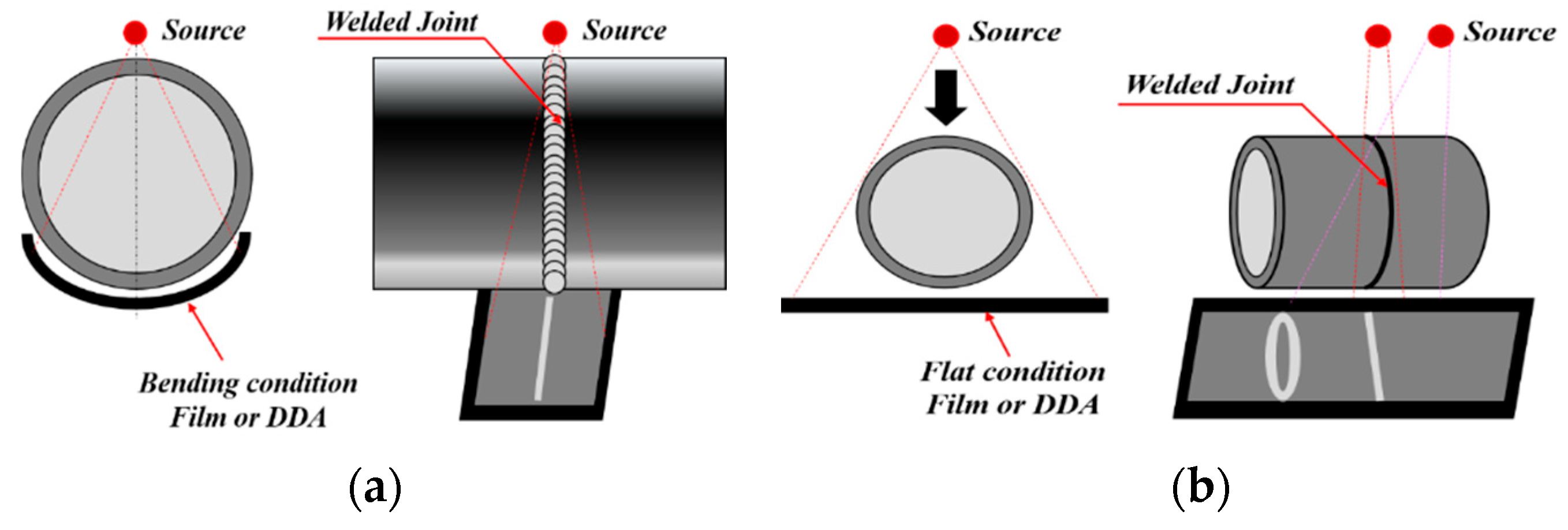
2.2. Selection of the Radiographic Examination Technique
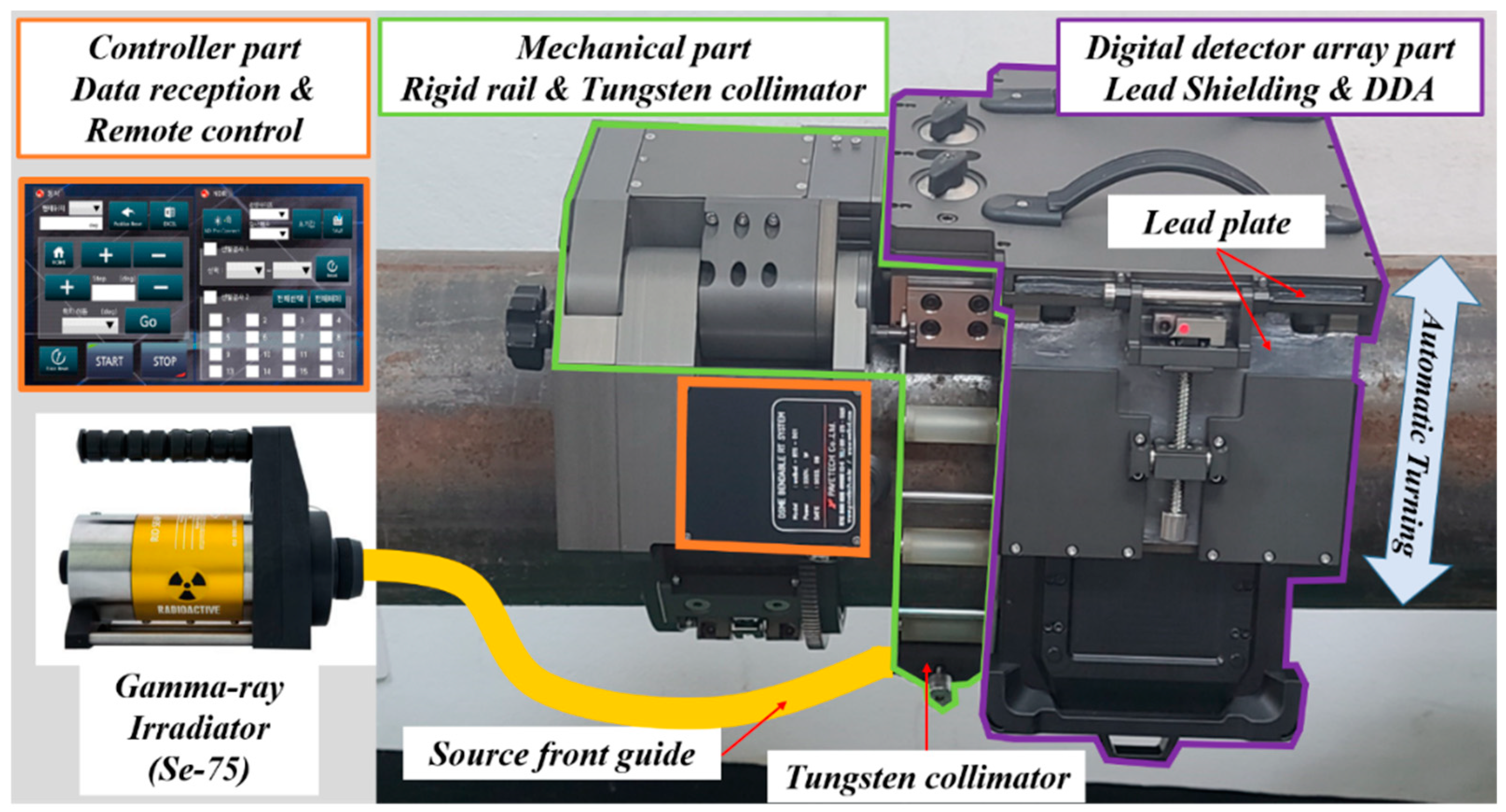
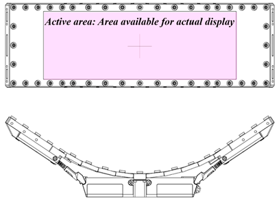
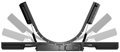
2.3. Configuration of the Orbital-Rail-Type Digital Radiography Inspection Device
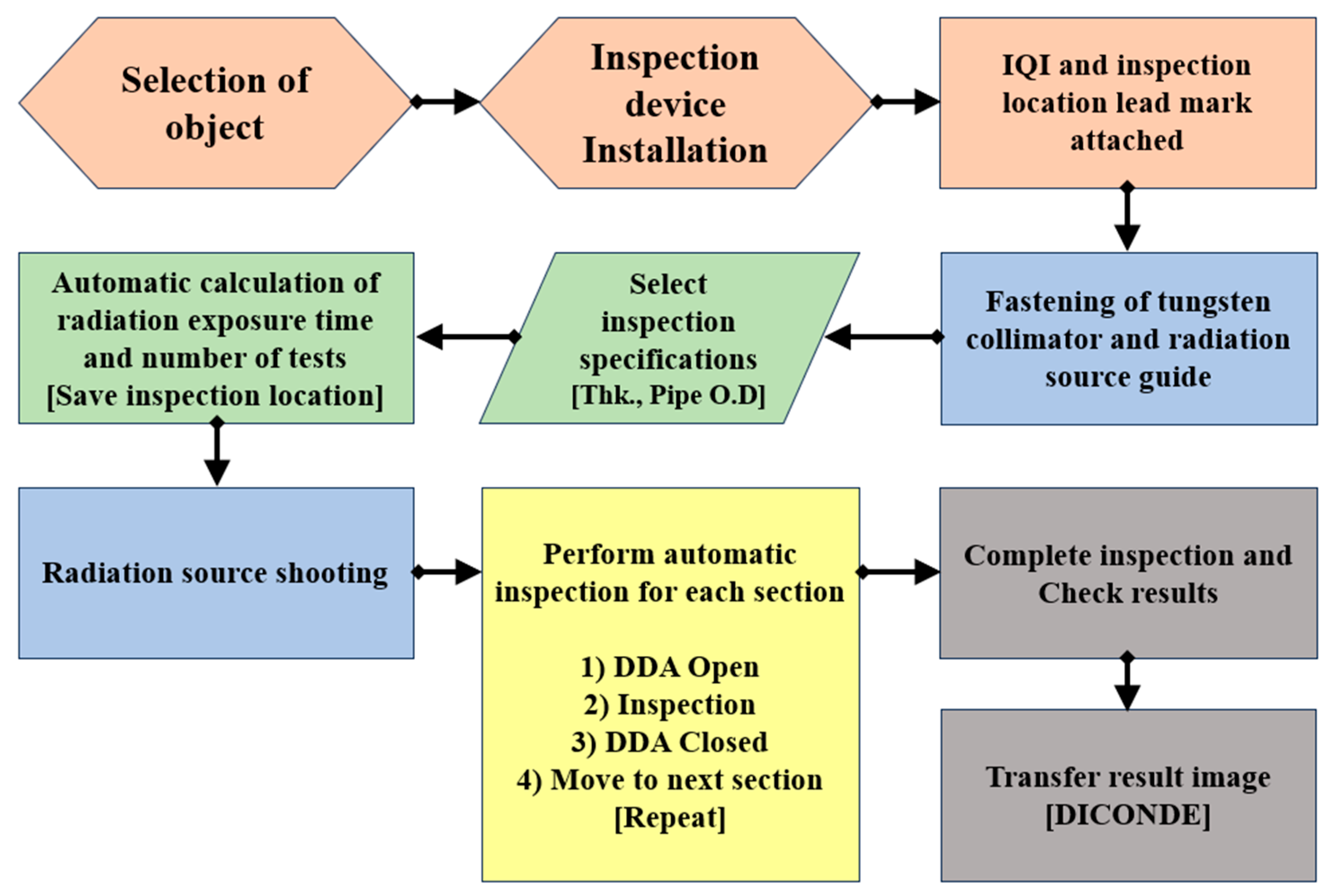
3. Development and Verification of the Inspection Device for Field Application
- (a)
- Formula for calculating the theoretical radiation dose rate.
- (b)
- Formula for calculating 1 μSv/h.
- (c)
- Ambient dose equivalent formula.
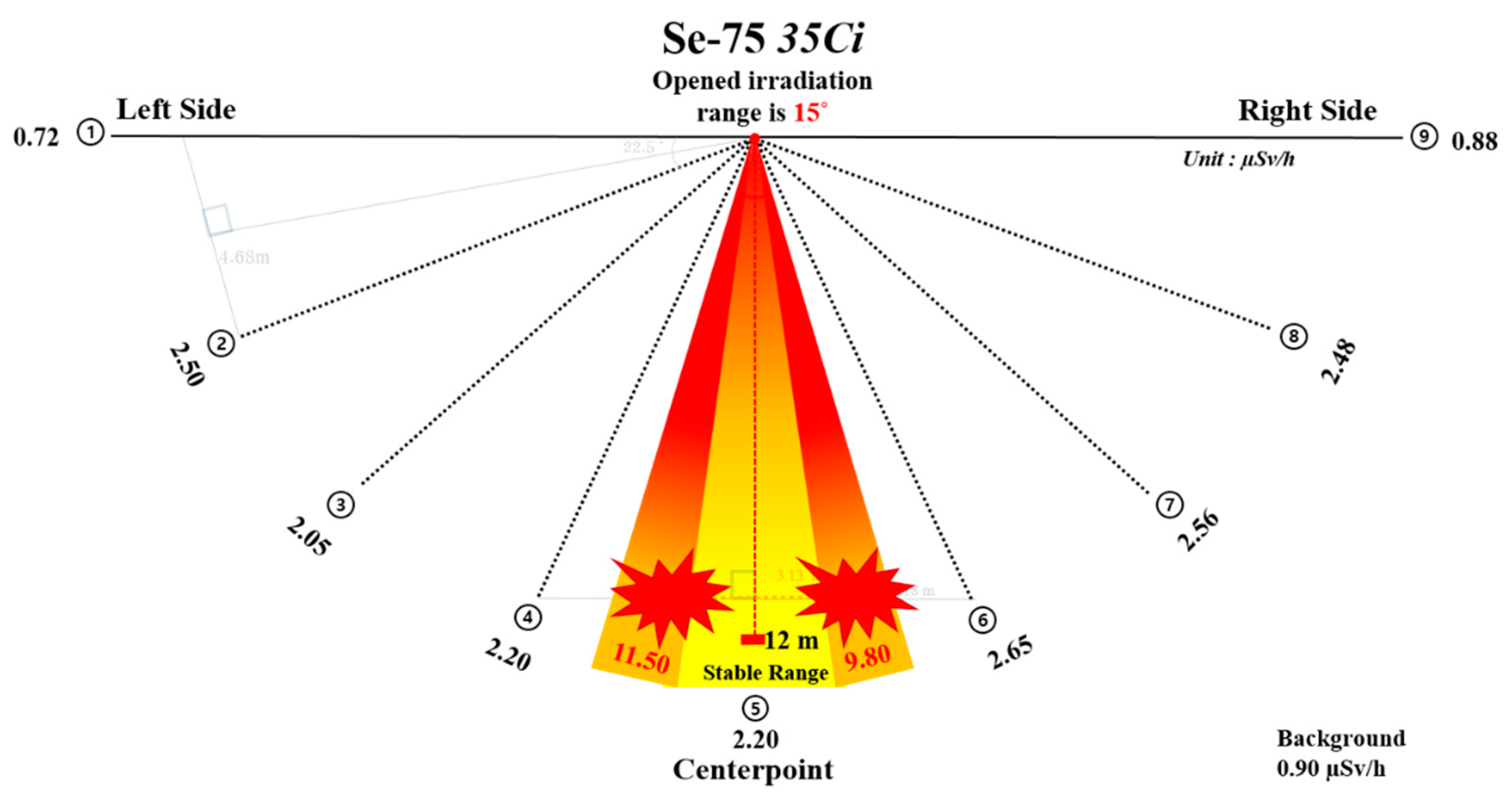
3.1. Radiation Shielding Performance Comparing FLUKA Code and Field Measurements
Field Measurements Using a Survey Meter
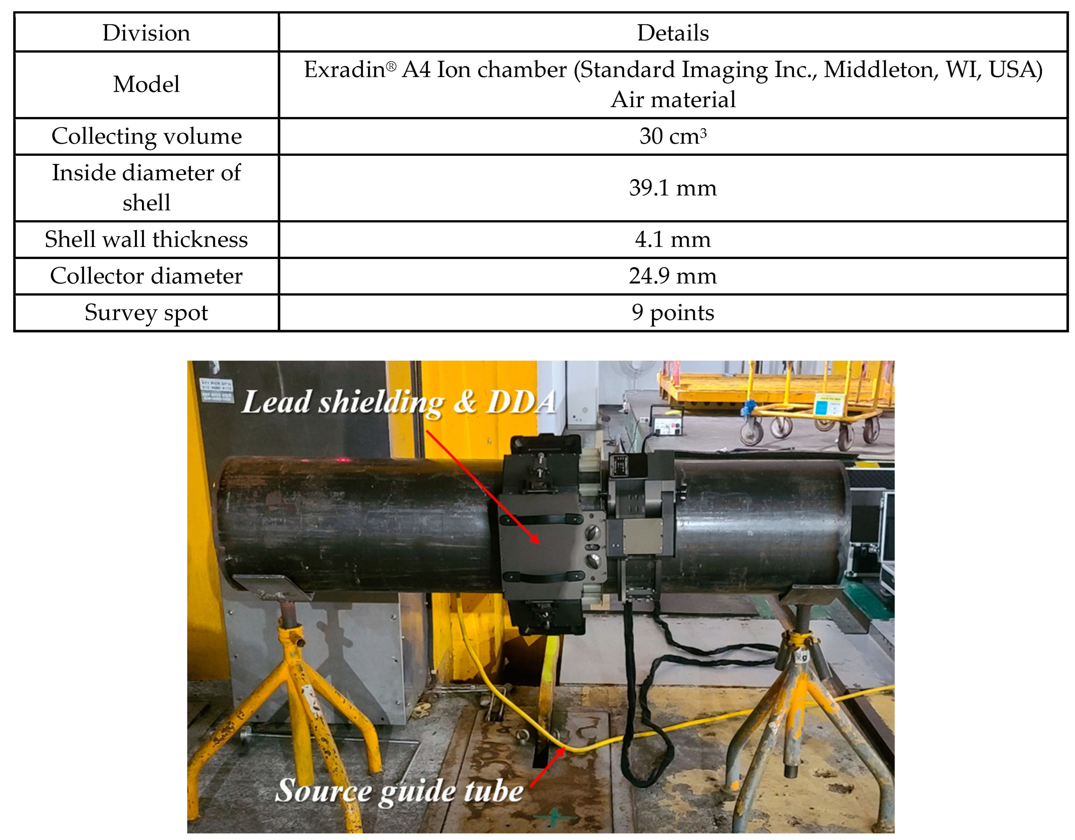
3.2. Cross-Assessment of Measurements Data through MCNP Simulation
3.2.1. Computer Simulation Evaluation Methods
- (a)
- Energy per decay in the ion chamber (E).S = Source Intensity
- (b)
- Absorbed dose in the ion chamber (D).
- (c)
- Ambient dose equivalent (H) formula.
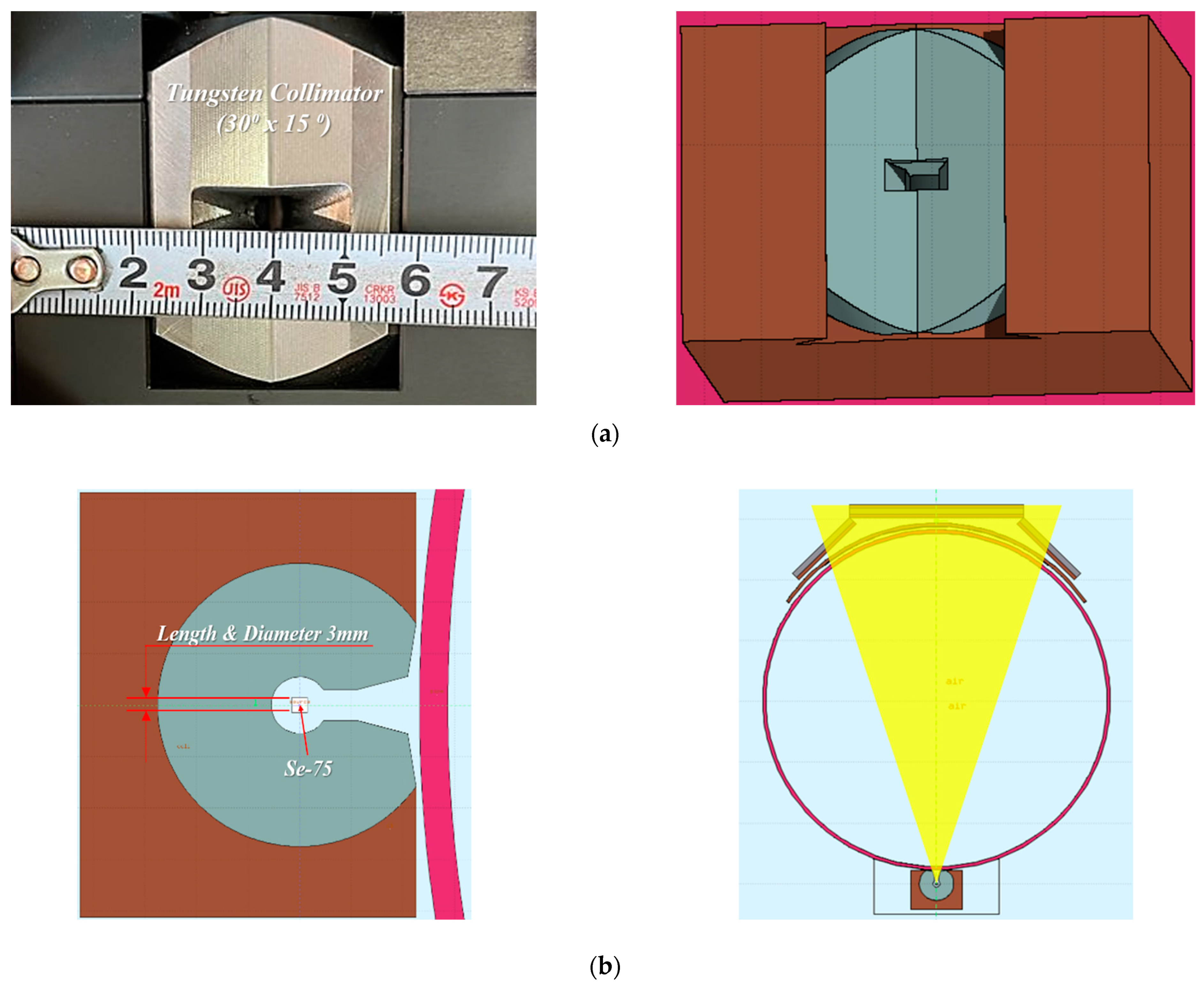
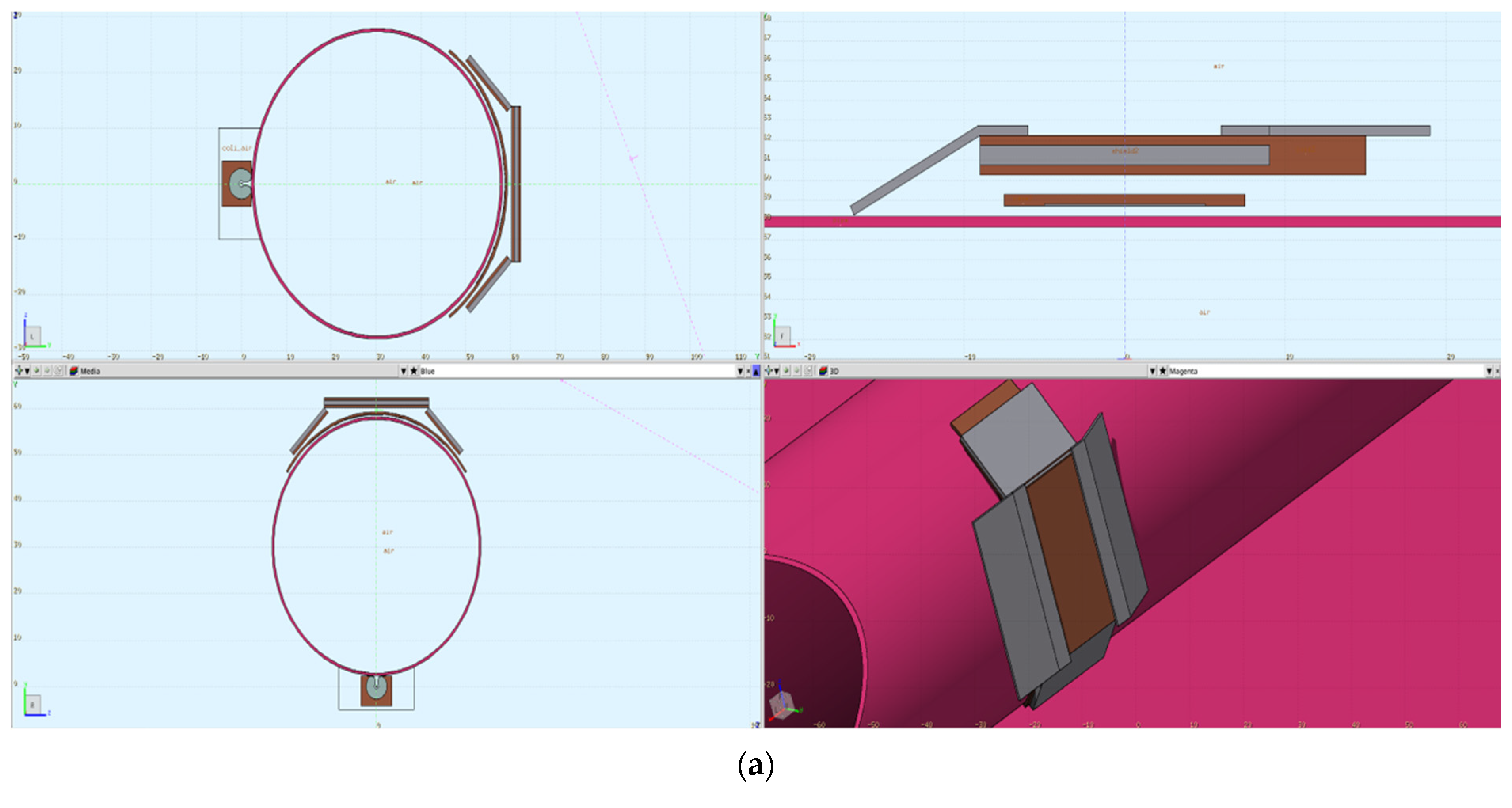
3.2.2. Geometry Modeling
3.2.3. Verification and Comparison with Field Measurements Using FLUKA Simulation
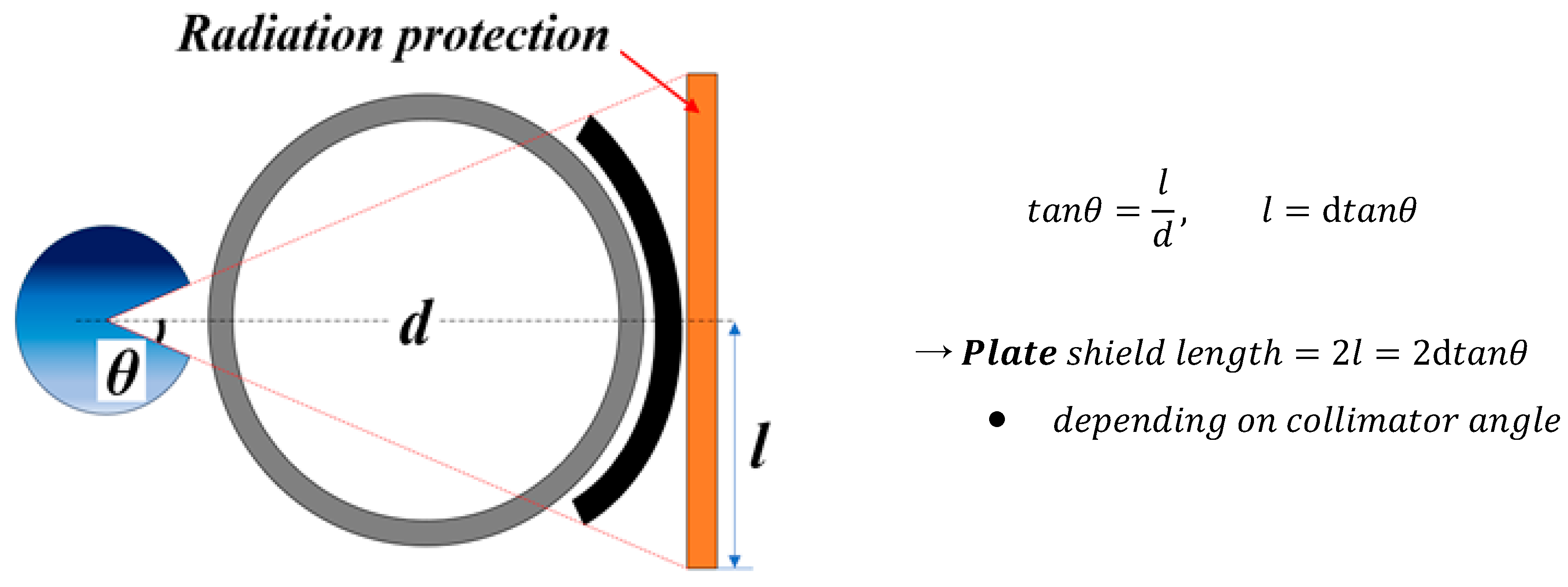
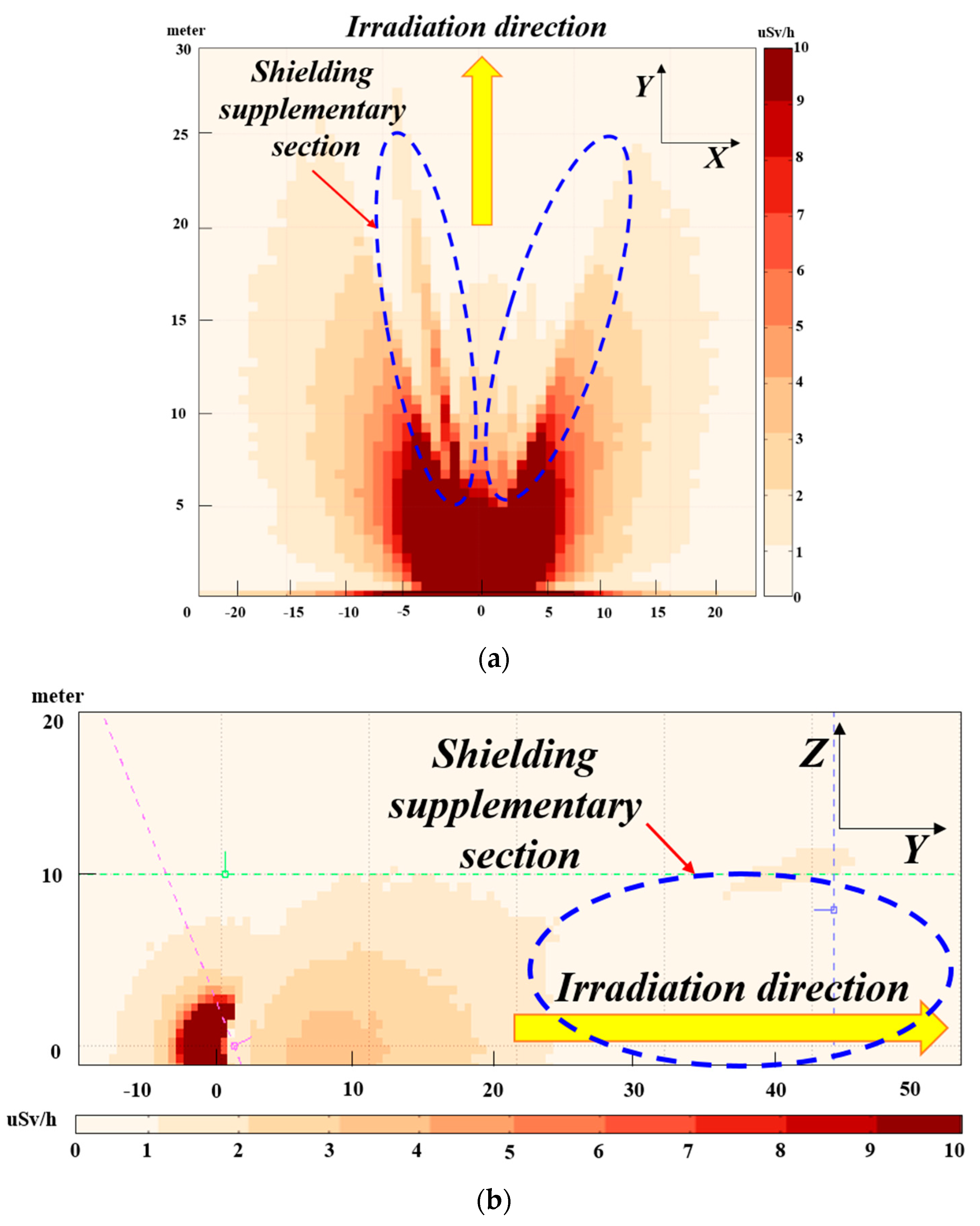
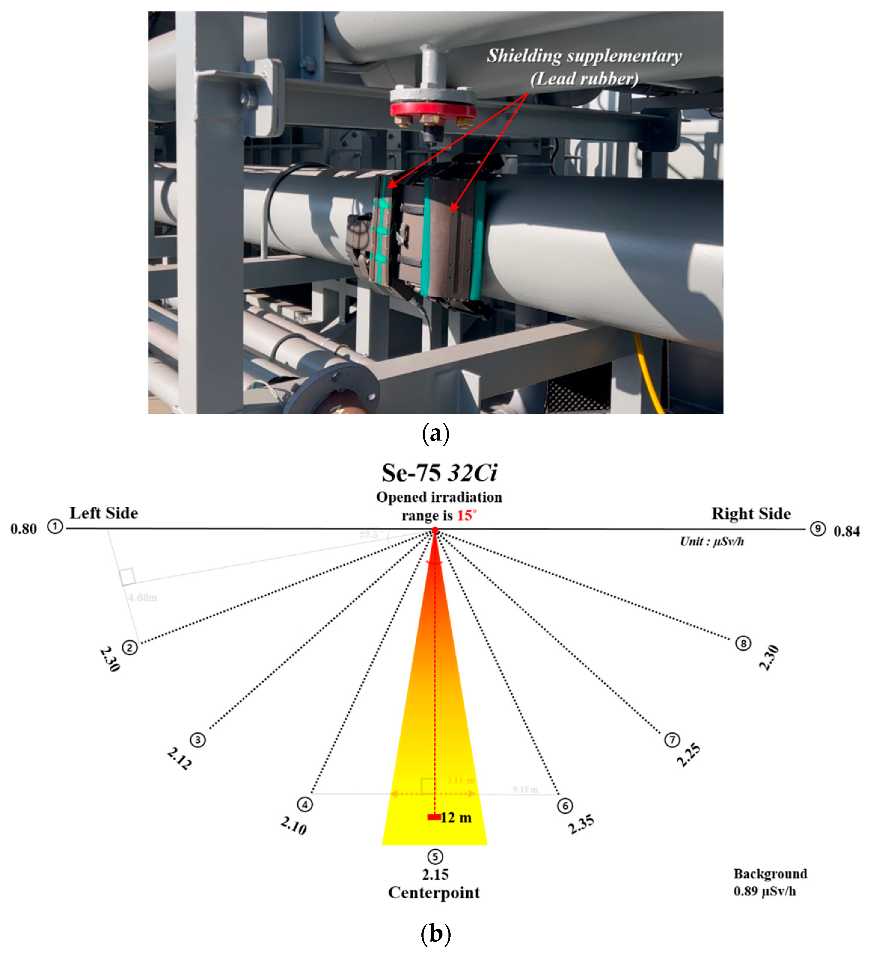
3.3. Complementation of the Shielding Area of Inspection Equipment
Geography Re-Modeling and Design
3.4. Comparison of Simulation Results and Field Measurements in Supplemented Shielding Conditions
4. Conclusions
- Using gamma rays instead of X-rays offers advantages for placing inspection equipment in narrow spaces between pipes. However, gamma ray radiography quality is generally inferior to that of X-rays. Specifically, the Se-75 radiation source can produce high-contrast images for thinner materials compared to Ir-192 and meets DRT quality standards.
- The theoretical calculation results from the conservative approach and the FLUKA simulation results differed by approximately 5 m from the safety distance and the error rate was small. However, concerning the leakage angle of the tungsten collimator through micro processing and the theoretical shielding area, the actual measured radiation dose and safety distance differed considerably. This phenomenon could be attributed to differences in the amount of scattering in the transmission path of radiation and different variables such as absorption and reflection.
- When applying the atomic regulation authority’s conservative safety constant in the theoretical formula, the corresponding distance was 21.6 m if the target dose of 1 μSv/h was satisfied. Because of using the inspection device with the supplemented shielding conditions through FLUKA simulation to test pipes installed in the field, a value of approximately 2.15 μSv/h was measured at 12 m. When converting this value using the inverse square law, the target dose of 1 μSv/h could be satisfied at approximately 17.5 m. This phenomenon could lower dose values measured in the field when compared to those in the simulation results because of the additional shielding effect of the surrounding structures.
- Through this study, we developed equipment capable of automatically inspecting welds by rotating them using radioactive sources. To further develop the equipment in the future, the following research directions and needs were identified:
- (1)
- Prolonged exposure to radiation in Digital Detector Arrays (DDAs) can introduce noise that may adversely affect image quality. Although this study confirmed satisfactory performance for pipe thicknesses around 10 mm, it is necessary to assess potential degradation in image quality with pipes of maximum thickness.
- (2)
- X-rays are essential as radiation sources that can produce the optimal quality of digital radiography tests. It is expected that there will be a need to develop inspection devices using small-sized X-rays that can be integrated into the equipment.
- (3)
- Lastly, it is expected that the development of an automatic inspection device using a video-type inspection method will be necessary to improve inspection efficiency. There will still be difficulties due to the image distortion of test results but research to overcome these and establish optimal conditions is expected to continue to be necessary.
Author Contributions
Funding
Data Availability Statement
Conflicts of Interest
References
- Kim, S.-T.; Yoo, J. Analysis of the radiological safety control level versus the exposure of radiation workers in South Korea from 2008–2017. Radiat. Prot. Dosim. 2019, 184, 98–108. [Google Scholar] [CrossRef]
- Lee, S.; Lim, J.; Yi, C.-G. The improvement of the regional regulatory governance system for radiation risk management: Spatial analysis on radiation hazards in South Korea. Sustainability 2022, 14, 966. [Google Scholar] [CrossRef]
- Silva, A.S.S.; Oliveira, D.F.; Gomes, C.S.; Azeredo, S.R.; Lopes, R.T. Evaluation of digital detector arrays systems for industrial radiography. Braz. J. Radiat. Sci. 2019, 07-02A, 1–12. [Google Scholar] [CrossRef]
- Tyystjärvi, T.; Virkkunen, I.; Fridolf, P.; Rosell, A.; Barsoum, Z. Automated defect detection in digital radiography of aerospace welds using deep learning. Weld. World 2022, 66, 643–671. [Google Scholar] [CrossRef]
- Moreira, E.V.; Rabello, J.M.B.; dos Santos Pereira, M.; Lopes, R.T.; Zscherpel, U. Digital radiography using digital detector arrays fulfills critical applications for offshore pipelines. J. Adv. Signal Process. 2010, 2010, 894643. [Google Scholar] [CrossRef]
- Bai, W.; Bueno, C.; Wong, B.S.; Wang, X. Generation of radiographic techniques for digital radiography applications. Insight Non-Destr. Test. Cond. Monit. 2009, 51, 327–331. [Google Scholar] [CrossRef]
- Duliu, O.G. X- and Gamma Ray Imaging (CT, PET and SPEC, Scintigraphy, and Radiography) Benefits and Risks. In Medical Imaging Methods, 1st ed.; CRC Press: Boca Raton, FL, USA, 2021; ISBN 9781003112068. [Google Scholar]
- Yenumula, L.; Acharya, R.V.; Lingade, B.M.; Borgohain, A.; Maheshwari, N.K.; Kumar, U.; Selvam, T.P.; Dash, A. Radiographic evaluation of gas tungsten arc welded joints used in nuclear applications by X- and gamma-rays. NDT E Int. 2019, 102, 144–152. [Google Scholar] [CrossRef]
- ISO 19232-1:2013; Non-destructive testing—Image quality of radiographs. Part 1: Determination of the image quality value using wire-type image quality indicators. ISO: Geneva, Switzerland, 2013.
- ISO 17636-2:2022; Nondestructive testing of welds—Radiographic testing—Part 2: X- and gamma-ray techniques with digital detectors. ISO: Geneva, Switzerland, 2022.
- American Society of Mechanical Engineers (ASME). Boiler and Pressure Vessel Code, Section V: Nondestructive Examination, Article 2: Radiographic Examination, T-270; ASME: New York, NY, USA, 2013. [Google Scholar]
- Beinke, C.; Ben-Shlomo, A.; Abend, M.; Port, M. A case report: Cytogenetic dosimetry after accidental radiation exposure during 192Ir industrial radiography testing. Radiat. Res. 2015, 184, 66–72. [Google Scholar] [CrossRef]
- Meisberger, L.L.; Keller, R.J.; Shalek, R.J. The effective attenuation in water of the gamma rays of gold 198, iridium 192, cesium 137, radium 226, and cobalt 60. Radiology 1968, 90, 953–957. [Google Scholar] [CrossRef]
- Arbol, P.M.R.; Garcia, P.G.; Gonzalez, C.D.; OrioAlonso, A. Non-destructive testing of industrial equipment using muon radiography. Philos. Trans. R. Soc. A 2019, 377, 20180054. [Google Scholar] [CrossRef]
- Jolly, M.; Prabhakar, A.; Sturzu, B.; Hollstein, K.; Singh, R.; Thomas, S.; Foote, P.; Shaw, A. Review of non-destructive testing (NDT) techniques and their applicability to thick walled composites. Procedia CIRP 2015, 38, 129–136. [Google Scholar] [CrossRef]
- Bak, W.S.; Heo, S.U.; Min, B.I. Benchmarking FLUKA Monte Carlo code with international measurement standard for air kerma. J. Instrum. 2020, 15, P12014. [Google Scholar] [CrossRef]
- Koh, W.Y.C.; Tan, H.Q.; Ang, K.W.; Park, S.Y.; Lew, W.S.; Lee, J.C.L. Standardizing Monte Carlo simulation parameters for a reproducible dose-averaged linear energy transfer. Br. J. Radiol. 2020, 93, 20200122. [Google Scholar] [CrossRef]
- DeMarco, J.J.; Wallace, R.E.; Boedeker, K. An analysis of MCNP cross-sections and tally methods for low-energy photon emitters. Phys. Med. Biol. 2002, 47, 1321–1332. [Google Scholar] [CrossRef] [PubMed]
- Battistoni, G.; Cerutti, F.; Fassò, A.; Ferrari, A.; Muraro, S.; Ranft, J.; Sala, P.R. The FLUKA code: Description and benchmarking. AIP Conf. Proc. 2007, 896, 31–49. [Google Scholar] [CrossRef]
- Androulakaki, E.G.; Kokkoris, M.; Skordis, E.; Fatsea, E.; Patiris, D.L.; Tsabaris, C.; Vlastou, R. Implementation of FLUKA for γ-ray applications in the marine environment. J. Environ. Radioact. 2016, 164, 253–257. [Google Scholar] [CrossRef] [PubMed]
- Yang, Z.-Y.; Tsai, P.-E.; Lee, S.-C.; Liu, Y.-C.; Chen, C.-C.; Sato, T.; Sheu, R.-J. Inter-comparison of dose distributions calculated by FLUKA, GEANT4, MCNP, and PHITS for proton therapy. EPJ Web Conf. 2017, 153, 04011. [Google Scholar] [CrossRef]
- Guembou Shouop, C.J.; Sang-In, B. Shielding design for high-intensity Co-60 and Ir-192 gamma sources used in industrial radiography based on PHITS Monte Carlo simulations. Eur. Phys. J. Plus 2020, 135, 784. [Google Scholar] [CrossRef]
- Abdul Aziz, M.Z.; Yani, S.; Haryanto, F.; Ya Ali, N.K.; Tajudin, S.M.; Iwase, H.; Musarudin, M. Monte Carlo simulation of X-ray room shielding in diagnostic radiology using PHITS code. J. Radiat. Res. Appl. Sci. 2020, 13, 704–713. [Google Scholar] [CrossRef]
- Ay, M.R.; Shahriari, M.; Sarkar, S.; Adib, M.; Zaidi, H. Monte Carlo simulation of x-ray spectra in diagnostic radiology and mammography using MCNP4C. Phys. Med. Biol. 2004, 49, 4897–4917. [Google Scholar] [CrossRef]
- Nazemi, E.; Rokrok, B.; Movafeghi, A.; Choopan Dastjerdi, M.H. Simulation of a complete X-ray digital radiographic system for industrial applications. Appl. Radiat. Isot. 2018, 139, 294–303. [Google Scholar] [CrossRef] [PubMed]
- Dwivedi, S.K.; Vishwakarma, M.; Soni, P.A. Advances and researches on non destructive testing: A review. Mater. Today Proc. 2018, 5, 3690–3698. [Google Scholar] [CrossRef]
- Scott, B.R.; Gott, K.M.; Potter, C.A.; Wilder, J. A Comparison of in vivo Cellular Responses to CS-137 Gamma Rays and 320-KV X Rays. Dose Response 2013, 11, 444–459. [Google Scholar] [CrossRef] [PubMed]
- Trauernicht, C.J.; Moosa, F.; Blassoples, G.; Okwori, E.; Nyoni, B.R.; Moyo, P.; Burger, H. Concrete density estimation of linac bunker walls using impact-echo testing. Phys. Medica 2020, 77, 43–47. [Google Scholar] [CrossRef] [PubMed]
- Ismail, M.P.B.; Sani, S.B.; Masenwat, N.A.B.; Mohd, S.; Sayuti, S.; Ahmad, M.R.B.; Mahmud, M.H.B.; Isa, N.B. Radiation attenuation on labyrinth design bunker using Iridium-192 source. AIP Conf. Proc. 2017, 1799, 050011. [Google Scholar] [CrossRef]
- Shiiba, T.; Kuga, N.; Kuroiwa, Y.; Sato, T. Evaluation of the accuracy of mono-energetic electron and beta-emitting isotope dose-point kernels using particle and heavy ion transport code system: PHITS. Appl. Radiat. Isot. 2017, 128, 199–203. [Google Scholar] [CrossRef]


| Items | Main Content |
|---|---|
| Restrictions on the use of radiation sources | (1) Ir-192, Se-75
|
| Control of public access during radiation work | (1) Restricted access area accessible to the general public
|
  | ▪ Scintillator type | Gadox |
| ▪ Pixel size | 140 μm | |
| ▪ Pixel matrix | 768 × 2304 mm | |
| ▪ Active area | 327 × 107 mm | |
| ▪ Internal shieling | 300 kV | |
| ▪ Wireless | Battery and WLAN | |
| ▪ Bendable | 8″ (O.D = 202 mm) |
| ▪ Radioactive isotopes: Se-75 (72 Ci) ▪ IQI: ASTM 1A, 1B EN 10 FE (ISO 19232-1) [9] ▪ Related standards: (1) ASME BPVC Section V: Nondestructive Examination (2) ISO 17636-2: Nondestructive testing of welds—Radiographic testing—Part 2: X- and gamma-ray techniques with digital detectors [10] | |||||
|---|---|---|---|---|---|
| No. | Size/Type | Thickness (mm) | Material | IQI Requirement (mm) | Acquired IQI (mm) |
| 1 | 2″ Pipe | 3 | Stainless steel | 0.20 (DWDI) | 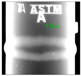 0.20 |
| 2 | 2″ Pipe | 5.5 | Stainless steel | 0.20 (DWDI) |  0.20 |
| 3 | 4″ Pipe | 13 | Carbon steel | 0.33 |  0.33 |
| 4 | 10″ Pipe | 4 | Stainless steel | 0.16 |  0.16 |
| 5 | 12″ Pipe | 15 | Carbon steel | 0.33 | 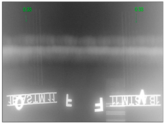 0.33 |
| ▪ Radioactive isotopes: Ir-192 (46 Ci) ▪ IQI: ASTM 1A, 1B EN 10 FE (ISO 19232-1) [9] ▪ Related standards: (1) ASME BPVC Section V: Nondestructive Examination (2) ISO 17636-2: Nondestructive testing of welds—Radiographic testing—Part 2: X- and gamma-ray techniques with digital detectors [10] | |||||
|---|---|---|---|---|---|
| No. | Size/ Type | Thickness (mm) | Material | IQI Requirement (mm) | Acquired IQI (mm) |
| 1 | 400 mm Plate | 10 | Carbon steel | 0.25 | 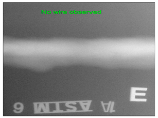 Not detected |
| 2 | 400 mm Plate | 15 | Carbon steel | 0.25 |  0.20 |
| 3 | 400 mm Plate | 20 | Carbon steel | 0.33 |  0.33 |
| 4 | 400 mm Plate | 30 | Carbon steel | 0.40 | 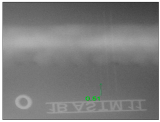 0.51 |
| HVL (mm) | Concrete | Lead | Tungsten | Steel |
|---|---|---|---|---|
| Se-75 | 30 | 1.0 | 0.8 | 8 |
| Division | Details | |
|---|---|---|
| Input Parameter | Input Card | Input Condition |
| Physical setting | Default | Precisio |
| Source term | Beam | Type: Isotope/Momentum |
| Hi-Prope | Type: Region Part: DOSE-EQ | |
| Scoring | Usrbin | Type: Region Part: DOSE-EQ |
| Auxscore | Set: AMB74 | |
| Transport | Emf-On | Type: Transport γ: 50 keV |
| NPS * | Start | No: 3.0 × 10¹⁰ |
| Type | Details | ||
|---|---|---|---|
| Blackhole area | Size | 100 m × 100 m × 20 m | |
| Evaluated area | Size | 50 m × 50 m × 20 m | |
| Shielded for Radiography Testing | Size | 200 mm × 380 mm | |
| Thickness | 10 mm (Lead) | ||
| Pipe (for inspecting) | Dia. | 500 A (out. 558.8 mm) | |
| Leng. | 10 m | ||
| Thickness of shielding material | 5.5 mm (Iron) | ||
| Source | Intensity | 47 Ci | |
| Active Source Size (Dia.) | 3.0 × 3.0 mm | ||
| Energy Spectrum (peak) | 97, 121, 136, 264, 279, 401 keV | ||
| Collimator | Angle range of irradiation | 30° × 15° | |
| Size | Leng. | 72 mm | |
| Depth. | 41 mm | ||
| Thickness of shielding material | 21 mm (Tungsten) | ||
Disclaimer/Publisher’s Note: The statements, opinions and data contained in all publications are solely those of the individual author(s) and contributor(s) and not of MDPI and/or the editor(s). MDPI and/or the editor(s) disclaim responsibility for any injury to people or property resulting from any ideas, methods, instructions or products referred to in the content. |
© 2024 by the authors. Licensee MDPI, Basel, Switzerland. This article is an open access article distributed under the terms and conditions of the Creative Commons Attribution (CC BY) license (https://creativecommons.org/licenses/by/4.0/).
Share and Cite
Kim, D.-S.; Heo, S.-H.; Heo, S.-U.; Kim, J. Orbital-Rail-Type Automatic Inspection Device for Pipeline Welds Using Radiation Dose Prediction Results from FLUKA Simulation. Appl. Sci. 2024, 14, 6165. https://doi.org/10.3390/app14146165
Kim D-S, Heo S-H, Heo S-U, Kim J. Orbital-Rail-Type Automatic Inspection Device for Pipeline Welds Using Radiation Dose Prediction Results from FLUKA Simulation. Applied Sciences. 2024; 14(14):6165. https://doi.org/10.3390/app14146165
Chicago/Turabian StyleKim, Du-Song, Sung-Hoe Heo, Seung-Uk Heo, and Jaewoong Kim. 2024. "Orbital-Rail-Type Automatic Inspection Device for Pipeline Welds Using Radiation Dose Prediction Results from FLUKA Simulation" Applied Sciences 14, no. 14: 6165. https://doi.org/10.3390/app14146165
APA StyleKim, D.-S., Heo, S.-H., Heo, S.-U., & Kim, J. (2024). Orbital-Rail-Type Automatic Inspection Device for Pipeline Welds Using Radiation Dose Prediction Results from FLUKA Simulation. Applied Sciences, 14(14), 6165. https://doi.org/10.3390/app14146165