1. Introduction
Unlike conventional design for manufacturability (DfM) methods and techniques, the design for additive manufacturing (DfAM) method [
1] provides significant freedom in comprehensive product design, allowing the creation of countless engineering solutions before the designer sends any data into production to build a final product or its prototype. Benefits derived from this design method ensure the creation of complex parts with tricky geometries and can guarantee parts production with improved mechanical properties. These benefits are supported mainly by creating and taking advantage of cell structure design oriented to additive manufacturing (AM), resulting in the product’s enhanced inner morphology and functional design. Creating freeform geometry is a relatively straightforward routine, but incorporating it into the macro design of components, simulating natural conditions, and component working environments is quite challenging [
2]. Parametric design has become more significant when it has become clear that additive-based technology can deliver complex-mathematically described geometric shapes like lattices with desirable quality defined by engineering or other rules [
3].
Cell structures can take various physical forms, but lattices have outstanding properties over other types like foams, such as being lightweight, having high strength, absorbing energy, and reducing vibration. Regarding its uniqueness, natural cellular materials have ideally served as the original form to develop artificial structures made from various materials like foams, ceramics, and a wide range of plastics. The latter material is the most widespread among end users and broad industry since the FDM method covers most of the market. Although many papers have dealt with lattice structures made of metal foams and liquids, this paper deals with polymer material, which served in physical lattice creation [
4]. Artificial lattice structures use basic unit cell shapes to make numerous repetition forms of interconnected cells. Repetition forms of lattice structures are realized throughout uniform and nonuniform lattice arrangements or, most frequently named, periodic and stochastic. Many papers have been researching both lattice types, considering their micro-architecture and primary unit cell shape variability [
5]. Lattices are composed of inter-connected networks of struts/beams if they are about circle cross-section or sheets/plates if they are about planar geometry, with broad end-use applications in getting a lightweight design for a product [
6]. Advanced computer-aided design (CAD) systems enable control over the lattice creation in various shapes and directions, as additive manufacturing simultaneously allows such intricate designs to be produced [
7].
The mechanical properties of artificial cellular materials are not uniform from the aspect of macro-design and differ depending on which shape and material they are made of. Therefore, three major factors determine lattice mechanical properties: the material from which they are made, relative density, and topology [
8,
9]. Relative density is the ratio of the lattice structure’s physical density
to the prime material’s density
. The relative density is typically controlled by cell unit size, number, strut thickness, or diameter. Topology is related to node connectivity, which presents the number of struts connected to a node and the shape of the structure’s cells. The influence of these three factors is well-investigated among researchers and widely implemented in various studies [
10,
11,
12]. Given the applied material, the significant contribution of most conducted studies refers to increased and decreased node connectivity. Increased node connectivity leads to more rigid structures with increased static strength [
13] and fatigue strength, while vice versa, it leads to more yielding because structures tend to flex under loading conditions.
However, from the other side, the contribution of these three influential factors is quite limited concerning the papers’ availability of data related to stochastic structures, particularly emphasizing the application of polymers. Still, the stochastic approach is well-suited for producing lattice parts with nonuniform geometry arrangements due to the struts repeating oriented at different angles and positions [
14]. Regarding the control of the design model of the stochastic structure, authors [
15] analyze geometries with varying degrees of nodal connectivity, ranging from bending-dominated to stretching-dominated, at different orientations and compare their responses. Still, results did not show a better mechanical response than periodic responses. In support of the results found in [
15], authors [
16] conducted research that considered lesser nodal connectivity levels than [
15] and found stochastic structures had inferior mechanical properties compared to periodic lattices. Besides nodal connectivity variations in the structures, some authors dealt with isotropy and anisotropy lattice properties to reduce the impact of printing direction. In the reference [
14], the authors presented a modified stochastic structure with great potential to be used as basic structures that achieve uniform stiffness in all directions. Some investigations [
17] went a step further and gave the first model to predict the anisotropic apparent modulus and strength of structures based on lattice density and fabric tensors, which are helpful in the mechanical design of components. If dealing with design models and various methodologies put aside, the authors [
18] also researched mechanical responses of the lattice structures with stochastic geometric defects originating directly from the additive manufacturing process. This research is curious because the findings revealed a higher prevalence of geometric imperfections in the horizontal struts compared to the diagonal or vertical struts.
Regarding defects and material properties, it is notable that the elastic properties of highly connected lattice-truss materials respond to defects in the same manner as homogeneous materials [
19]. This study investigates the dependence of the elastic moduli on the concentration and distribution of missing struts for several truss-lattice materials. This means the examined structures were characterized by many material defects but without significant influence on the elastic properties of the design. On the other side of the stated problems related to the additive technology process, some researchers [
20,
21] investigated how laser energy and scan strategy affect strut thickness and mechanical strength of porous materials. Processing parameters [
22] significantly control the quality of lattice parts’ mechanical properties, especially in micro-lattice block structures.
Research Objectives
This work emphasizes the significance of optimizing processing parameters to maximize mechanical performance. Considering these mentioned sources and analyzing important printing physical aspects such as isotropy or anisotropy and material defects are both crucial in getting accurate asses of the internal structure state for ensuring optimal mechanical responses regardless of design models. If it approaches closer to the state-of-art of current implemented studies, processing parameters hold the mechanisms in defining primary mechanical issues. An extensive list of papers is devoted to researching the ability of a material to have the same properties in all directions. This characteristic is expressed in periodic repeating cubic unit cells [
23,
24]. Stochastic structures offer alternatives since they use distributions of points generated algorithmically. A big challenge in creating stochastic structures is attributed to variable anisotropy in different directions.
Considering the previous, it is reasonable to determine that the proposed methods and design models must be revised to ensure a desirable mechanical response of stochastic lattices. The selected strategies did not deliver the assigned assumptions and showed inferior or, at best, unreliable results. Therefore, there is a need to understand better how stochastic structures’ topology and geometry impact the behavior and mechanical properties. This research aims to investigate semi-controlled stochastic structures based on the proposed design method to analyze uniaxial loading, which imitates the actual state of the component within the assembly functioning. The goal is to determine the behavior of stochastic arrangements, predict internal mechanics, and contribute to their optimized response.
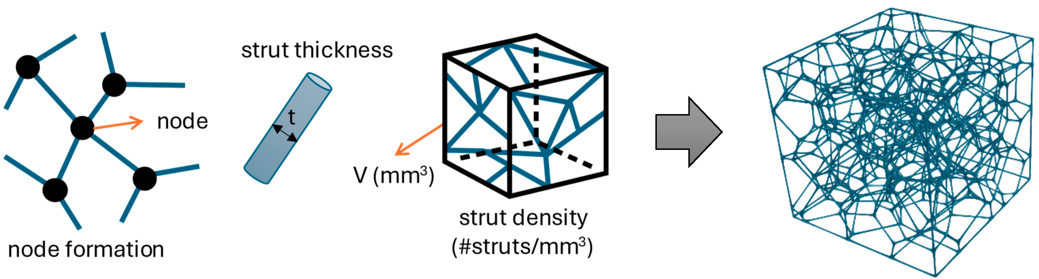
Regarding these statements, this paper’s hypothesis is to introduce a new design model based on predefined topologic and geometric routines to control the mechanical response of stochastic lattice structures. Three design parameters were used to define the structure: node formation (topology), strut thickness, and pattern of lattice generation (geometry) to fully describe the structure and correlate these to relative density. If successful, this would enable the importance of correlating these three design parameters to regulate a structure’s properties like stiffness, strength, and porosity. Besides these three, the impact of cell geometry enables changes in Voronoi tessellation, contributing to significant modifications in mechanical properties [
25]. The well-known Gibson-Ashby model [
26,
27] is the suitable starting point for this, which correlates significant mechanical properties, such as elastic modulus and strength, to relative density. The Rhinoceros 7 (Robert McNeel & Associates) was used to conduct all assigned model design goals.
The novelty is in the design approach of impacting the volume tessellation to get a semi-controlled stochastic arrangement of struts and nodes for a reliable mechanical response to outer forces. The proposed novel design approach ensures a geometric routine based on a mathematically defined parabolic entity to create a parabolically shaped surface extending inside the predefined volume’s boundaries, finally serving to distribute points (Voronoi seeds) to generate a suitable structure. Novelty is additionally founded on the fact that no one has yet used a parabolic-shaped surface bounded and positioned by the product volume’s dimensions to form a lattice structure. Simultaneously, the design mechanism parallel controls internal structure generation by purging and regulating adjacent points situated too close to each other, thus avoiding abnormal knots. As a result, it contributes to eliminating stress concentration cusps, leading to an enhanced mechanical response to an external force acting.
The impact of material defects and variations of processing parameters related to the nature of additively manufactured parts are not considered in the proposed model. This is attributed to the utilization of Stratasys F270, a closed fused deposition system that guarantees highly accurate and superior quality printed parts for this additive method.
2. Material and Methods
2.1. Initial Material Characterization
The tensile stress-strain curve of a bending-dominated lattice’s prime material is linear elastic with the modulus (Em) up to its elastic limit. At this point, the cell edges yield, buckle, and fracture. Regarding the reliability and correctness of experimental and numerical results in lattice mechanical response investigation, prime material characterization from which lattice structures were made.
Acrylic Styrene Acrylonitrile (ASA) [
28] filament was selected for material characterization. It is ASA Black filament, type F900-T16 Tip, manufactured by Stratasys (Eden Prairie, MN, USA), with yield strength (S
y) of 32.8 MPa, elastic modulus (E
m) of 2140 MPa, elongation at yield point (E
y) of 2.5%, and elongation at break point (E
b) of 5.9%. ASA black specimens for testing purposes were printed with 0.254 mm layer height. Due to the anisotropic nature of FDM, tensile curves are different depending on orientation. So, for the proposed methodology, specimens were tested in the printing direction since the intention is to ensure that specific determined stress conditions can be effectively applied to the macro design of a component. Pretty good mechanical properties define this FDM thermoplastic polymer, making it extremely powerful in this class. It was initially developed as an alternative to Acrylonitrile Butadiene Styrene (ABS) [
29], with a similar molecular structure but significant improvements. Due to its additional composition, which provides better resistance to ultra-violent radiation, it has become a widely used material in the industry. It is called an engineering plastic because it is impact-resistant and stable in different weather conditions, emphasizing that it can withstand high temperatures well.
Due to the material’s high glass transition temperature, a heated bed is required to print successfully. Thus, for the best results when printing with ASA, the printing speed was 50 mm/s, the extruder temperature was 245 °C, the bed temperature was 100 °C, and the heated chamber was enabled. As suggested by the ASA printing tips [
30], to avoid initial layering problems, the extruder temperature processing parameter was decreased by 5 °C compared with the mid-range values. As the manufacturer declared, everything beyond these parameter processing values decreases the quality of the printed specimens. The most critical issues when working with ASA are the warping effects, so it must avoid high-temperature processing values. Thus, it is strongly recommended that these processing values be followed.
Therefore, the prime’s material characterization for determining the tensile properties was carried out per ISO 527-2 [
31]. Specimens are firstly modeled following dimensions of specimen type 1A (
Figure 1). FDM additive manufacturing method (AM) enabling Stratasys F270 from the F123 series, an industrial-grade device, was used in manufacturing testing specimens. Since FDM was selected to realize testing specimens, additive manufacturing was performed using a standardized [
32] technique of dispensing thermoplastic polymer through a hot nozzle named Material Extrusion (MEX) [
33]. MEX is a significant method characterized by its fundamental technical capabilities contributing to materials science [
34]. Based on those capabilities, MEX allowed the development of the proposed design model through the following prototypes in this paper. According to standard guidelines, five specimen designs were printed using a solid infill structure with minimal support material usage. All specimens were transferred to the universal testing machine at standard room temperature. Testing equipment was based on the Shimadzu AGS-X machine (Kyoto, Japan) with TrapeziumX software v1.5.6 containing imported standardized testing rules following the ISO norm. All specimens were tested individually, and then, as can be seen later in the figures, all results were loaded and overlapped into one diagram chart along with the resulting values.
The tensile properties were characterized and written according to the subject standard [
35], adhering to symbols and abbreviations to comply with the ISO/IEC directives. The testing process was set according to the assigned standard, assuming that yield and maximum tensile stress match (Equation (1)), while tensile stress at break and maximum tensile stress do not match (Equation (2)).
If so, according to Equations (1) and (2), elongation between points of Ey and Eb is the main feature of this examination that characterizes prime material and must be considered thoroughly.
The FDM Stratasys F270 3D printer from the F123 series was used in manufacturing testing specimens. Specimens are modeled according to the ISO 527-2 standard, specimen type 1A. The specimen’s cross-section dimensions are 10 × 4 mm. Five specimen designs were printed using a solid infill structure with minimal support material usage. All specimen designs were melted in a liquid bath for 24 h at 60 °C. The Shimadsu AGS-X, a universal testing machine with a 100 kN load cell capacity, and TrapeziumX software were utilized for testing and processing results.
2.2. Nodal Connectivity Optimization Design Model
The primary focus at findings of earlier available research data related to stochastic open or closed cells is the type of deformation for most lattices, or whether it would be stretch or bending-dominated under the loading. Still, despite numerous research findings and results, a wide specter of applied materials and designs caused stiffness and strength, in correlation with relative density, to fall far below the assigned assumptions.
According to the findings of the reference [
26] regarding a stochastic cellular structure, the topology of the low-connectivity cells causes the edges of the cells to bend when the structure is loaded. Even when the cells are closed, the deformation primarily bends constituents since the thin cell faces buckle easily.
Figure 2 shows a typical open-cell stochastic lattice made from struts connected in joints or nodes.
Previously, most significant studies have focused on connectivity phenomena [
8,
15], defining the number of struts that meet in the node. Unlike them, if the focus moves from the variable nodal connectivity degree to the nodal formation definition, it creates space to decrease the number of nodal imperfections in lattice composition. By this, the first sub-hypothesis takes the significance of nodal tolerance definition in getting valid formation. It implies introducing a controlled mechanism for nodal formation based on tolerance value to ensure lattice correctness since no authors have dealt with lattice validity lately. This assumption returns the process to Voronoi tessellation and investigates whether all struts and nodes make the structure valid. If the loading primarily bends constituents, causing the thin cell faces to buckle easily, whole volume tessellation must be reviewed.
Voronoi tessellation populates volume geometry, ensuring a series of random points inside the defined boundaries using two major parameters definition: the number of points to add and a random cell seed for insertion. The tessellation causes polygon’s corners where topological formation retains sharpness, and as a response, it piles up a more significant number of nodes, making topology arrangement more complicated. This means that tessellation causes excess points concentrated at a relatively small curve distance, which is considered to have an irregular topology arrangement.
Figure 3 shows the interior of a structure, where the blue arrow indicates a distance between two points, obtained by measuring distances between each point in the cluster that is less than allowed to form a regular node. Node formation based on this unallowed distance causes shape irregularity, leading to the appearance of notches and creating stress concentrations. Therefore, the proposed design model ensures an algorithmic routine to prevent the appearance of these irregularities, eliminate notches and, thus, errors in node formation, and improve not only a mechanical response but also the visual appeal of the lattice.
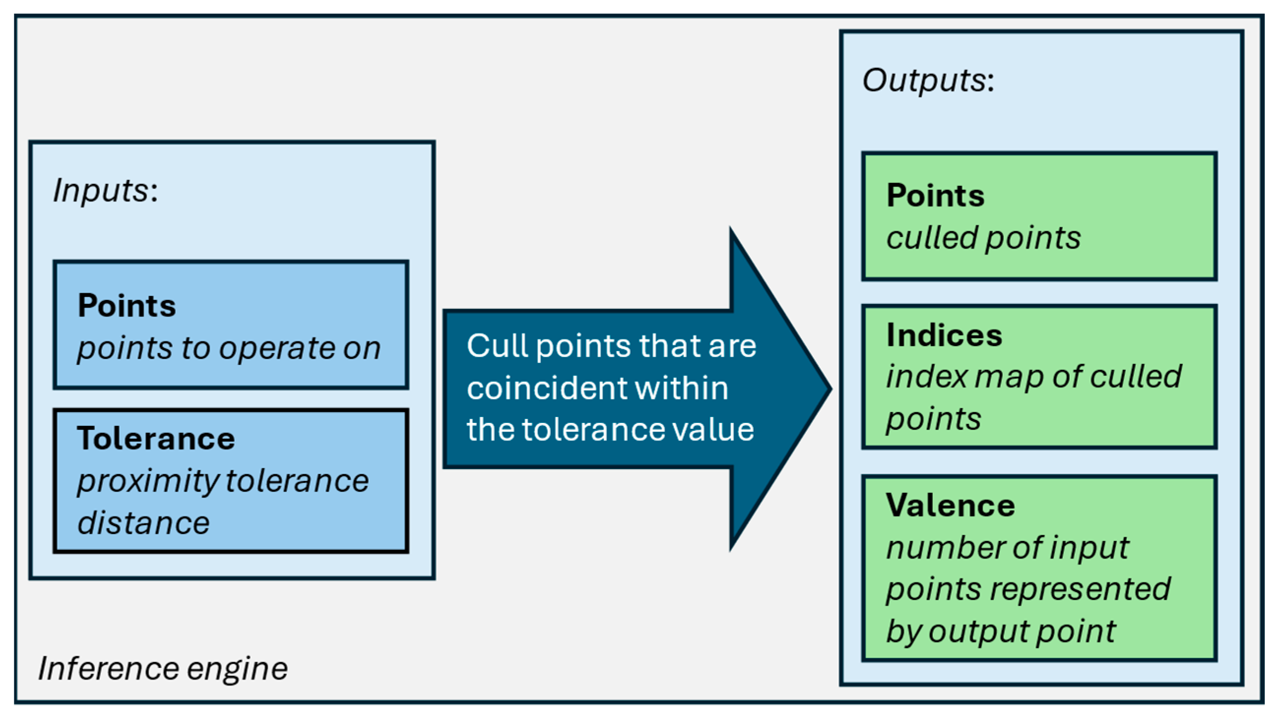
Now, nodal connectivity is considered through the winged-edge data structure, using edges to control and keep track of overall topological formation. Edges are used to make line discontinuity and achieve point recognition. Upon the points (nodal) recognized, the tolerance value for defining minimal nodal distance is introduced to prevent points from piling up. The goal is to cull inconvenient points for regular topology formation, resulting in retaining a suitable point using tolerance value (
Figure 4).
It is crucial to underline that tolerance value correlates with strut thickness and must be adjusted to be not much greater or lesser than the thickness value. Besides strut thickness, lattice volume impacts the tolerance value. The algorithm tracks the winged-edge structure and, based on the defined tolerance, seeks two or more points having a distance equal to or lesser than the tolerance value to merge them into a single point. Newly created points make a polyline-wired structure, creating a new relief pattern for each cell at the boundary region. Polylines replace old relief topology with a new active pattern that must be closed-loop. Given the new nodal formation, the Voronoi cell structure has no sharp corners, and all polygons look topologically correct, ensuring better nodal connectivity when strut thickness is applied. The algorithm is critical to eliminating small gaps and grooves in the structure’s configuration, preventing residual stresses from occurring, which is the starting point for a lattice structure to be topologically validated and gives the possibility to make results more uniform and reliable.
The stochastic open cellular structure consists of solid struts surrounding a void space. When analyzing bending-dominated stress states of stochastic open cellular structure, it is crucial to consider significant mechanical strength criteria in correlation with relative density. Having started from the fact that cellular solids are characterized by their relative density [
26], for which the structure is defined as follows:
where
, is the density of the lattice structure,
is the solid prime material’s density,
is the cell size, and
is the thickness of the cell edges. It follows from this that relative density plays a critical role in mechanical property determination.
However, controlling the number of struts for different seed orientations in stochastic tessellation, and thus relative density, which varies depending on the strut number, has been challenging. Having analyzed this, the Gibson-Ashby model was the starting point for most papers that have tackled this issue, where remote compressive stress exerts a force
on the cell edges, causing them to bend, leading to a bending deflection for a value
:
This expression in Equation (4) is related to a horizontally oriented strut length
, loaded at its mid-point by force
, causing deflection, where
is the modulus of the solid of which the strut is made, and
is the second moment of area of the cell edge of the circular cross-section. The approximate compressive strain experienced by the entire cell is equal to
. Assembling these values will give the following relationship:
2.3. Test Specimen Generation
Considering deflection principles under the remote force acting on the structure, the bending-dominated nature of the structure’s constituents, and the impact of relative density in a function of struts number, there is a need for a better understanding of mechanical behavior inside the lattice. Typical Voronoi tessellation ensures the randomized arrangement of cells within certain volume boundaries. This randomized cell arrangement results in a nonuniform open-cell lattice named a stochastic structure. The curiosity is that the user has no control over the stochastic cell arrangement except for defining input parameters such as cell count and seed. The second sub-hypothesis proposes establishing a predefined geometric routine to arrange the cells, introducing a semi-controlled mechanism over points’ distribution in tessellation. It means that stochastic lattices were designed using Rhinoceros 7 software by filling a cuboidal volume of 50 × 50 × 50 mm
3 with pseudo-randomly distributed points [
8,
14] along a predefined geometric pattern. Cell arrangments like this aim to predict deformation and make the structure’s mechanical response more uniform and reliable, unlike in stochastic cases, which do not ensure it. This means defining a parabolic pattern as the geometric base for the randomized points distribution of the Voronoi tessellation (
Figure 5).
The parabola’s height (
) is a geometric entity positioned inside predefined volume boundaries (any volume dimensions) determined in four dimensions:
(
Figure 6).
Therefore, the proposed design model ensures the routine of randomized point arrangements along the parabolic surface, including its varying heights, which can impact a structure’s mechanical response. The proposed design model aims to establish a semi-controlled mechanism over tessellating an uncontrolled number of struts, thus significantly affecting the lattice’s density change.
Following the proposed design model, lattice structures for experimental testing were modeled in 125 cm
3 (50 × 50 × 50) volume using a Rhinoceros Grasshopper parametric module. Experimental testing aims to show and assess the mechanical behavior of lattice structures made following the proposed design model guidelines, starting from typical Voronoi tessellation (randomly distributed) and shifting to the topological and geometric predefined routine for Voronoi tessellation (semi-controlled). The experimental testing plan includes printing each lattice in five specimens per selected seed for each design model (DM) and repeating all series for another seed position (
Table 1).
Regarding the population density and the number of points that must be populated inside the volume, ten points in total were used for distribution for all model designs. This means that ten points in total were arranged randomly in both designs, typical Voronoi tessellation and along the parabolic surface tessellation.
2.4. Experimental Testing
Five specimen designs were printed out of already defined ASA Black filament, type F900-T16 Tip, on the FDM Stratasys F270 3D printer using a solid infill structure with minimal support material usage. All specimen designs were melted in a liquid bath for 24 h at 60 °C. The Shimadsu AGS-X, a universal testing machine with a 100 kN load cell capacity, and TrapeziumX software were utilized for testing and processing results (
Figure 7).
The compression testing was performed in laboratory conditions at a room temperature of 22 °C. Compressive flat plates were installed and used on the universal testing machine, with defined static pre-stressed conditions depending on the specimens’ heights, having measured from the lower compressive plate. All specimens were cut off (during 3D modeling) in a top and bottom plane to be adjacent to the compressive plates better when touching. At a slightly higher height than the specimen’s height, the testing machine’s traverse moves at a constant strain rate until it detects a force of 10 N. This force results from the contact between the surface of the compression plate and the structure’s upper cut-off surface. After this point occurs in the force-displacement curve, the pre-stressed condition ends, and the primary load condition begins. The traverse moves constantly between these two load conditions. As a proposed minimum according to ISO 2602 [
36] and ISO 527-2 normative, five test specimens were used in the testing procedure for each design model, where the confidence interval supports the evaluation of the derived results.
2.5. Finite Element Analysis Model
A Finite Element Analysis (FEA) model is a numerical representation of a physical system that uses a mesh of discrete elements to approximate and solve complex engineering problems involving stress, strain, thermal, or other field variables under given boundary conditions and loads. It is necessary to emphasize the importance of acquiring precise material properties to analyze key characteristic parameters, their response, and the scale of localized stresses.
Besides tensile stress and Young’s modulus, the tangential modulus of elasticity plays a significant role in the numerical model parametrization. The tangent modulus is the slope of a line tangent to the flow curve featured at a plastic point of interest. Following recommendations from [
37], the Ansys software (v.17.1) utilized a multilinear isotropic hardening material model.
The FE model (
Figure 8) is sandwiched between a moving flat surface (defined displacement load condition along negative Z) and a fixed flat surface (lower cut-off surface). Given the computational efficiency and significant deformation due to lower relative density, a large deflection was used in quasi-static testing. The reaction forces are measured in the upper lattice area and numerically linked with the displacement of the upper contact surface opposite the fixed flat surface. Analog to experimental testing results, charts, and the appearance of maximum forces, the displacement value along the negative Z axis was set at 1 mm of deformation (parameterized FE model).
A parameterized FE model featuring a 50 × 50 × 50 tessellation was established using the standard mesh element discretization. Due to the low relative density of the structures, the numerical model considers large deflection in the parametrization setup. It implies that the stiffness is no longer a constant but varies as it progresses through the load path. Thus, tangential stiffness represents the tangent to the force-deflection curve at a particular point in the load path. Therefore, numerical parametrization involves the time stepping in loading conditions. This will force the parameterized FE model to apply the load in smaller steps. It calculates an optimum time step at the end of each substep based on the structure’s response to the applied loads. The numerical model aims to iterate loading conditions until the residual becomes acceptably tiny and the solution is converged.
Generally, the manufacturing process significantly influences the mechanical properties of additively manufactured lattice structures [
38]. Although similar “printing defects” were expected to occur in all specimens, this study did not focus on including any of these imperfections. As a result, the modifications of the hardening model were not impacted by these defects. Therefore, the modified volumetric hardening model shown in reference [
14] was not used to establish a numerical material model in this research. The intention of establishing a multilinear isotropic hardening model was to separate material definition into two independent effects of elastic and plastic behavior and, thus, achieve different temperature-dependent data sets where the elastic modulus significantly impacts that region and plastic strain-stress behavior after the yielding process begins.
Concerning the accurate determination of the hardening model, stress versus plastic strain data points must be specified, starting from the yield stress of the prime material. This means that the starting point in the multilinear isotropic hardening model is the yield stress value, and the plastic strain is zero. These data serve in the numerical model for internal calculation of the tangent modulus for every two consecutive data points in the plastic region.
4. Discussion
If one examines the charts (
Figure 11 and
Figure 12) closely, the mechanical response increases as the height of the parabola extending decreases. Besides, maximum forces are achieved in smaller distances along the displacement axis, between 1.1 and 1.2 mm of deformation, which makes results more reliable for those design models.
Also, with the decline in parabolic height, the results seem more coherent, and force-displacement curves got closer to each other. If the data in
Table 1 are considered carefully, one can notice that as the height of the parabolic surface drops off, the relative density slightly increases. This leads to the significant novelty that by reducing the height of the parabolic surface, the tessellation increases the number of struts and, thus, the relative density of the stochastic structure. This implies the notable fact that the more the parabola extends through the volume, the tessellation builds fewer struts, so the relative density drops off and vice versa. These findings prove that the position and size of the geometric parabolic surface that serves as the basis for Voronoi population distribution directly affect the relative density of the tessellated model. Even slight differences in relative lattice structure density lead to drastic differences in mechanical response. This clearly implies that it is possible to control the mechanical response of the stochastic structure and even improve it in some segments. A degree of increasing linear dependence between relative density and stiffness is evident in design models that were tessellated based on a parabolic surface distribution (DM2 to DM5), which proves the significant influence of geometric parabolic arrangement of struts and topological validness of node formation. From another point of view, typical tessellation based on a random point distribution has the lowest relative density but has provided a significant response compared to DM5. However, the inability to predict the possible strut and node arrangement inside the structure is a massive disadvantage in seed-changing. The lack of any geometric law impacting the creation of internal structures results in the inability to predict any mechanical response related to stress acting in any direction. Uniaxial compression tests on lattice blocks highlighted the effect of design parameters on the mechanical properties of parabolic tessellated structures. A linear relationship was found between the plateau stress and elastic modulus relative to the measured relative density.
On the other side, in both cases, FE analysis delivered lower results than experimental testing, which corresponds to the findings of Zhou et al. [
18], who pointed out that actually printed structures are more resistant and yield, buckle, and crack later than FEM structures.
It must be highlighted that experimental maximum forces are recorded at the highest chart peak, which is significantly behind the 1 mm deformation. It means doubtfully that experimentally recorded forces are objectively higher and belong beyond the elastic area or precisely to the maximum tensile stress area. That is why those obtained by FE analysis are significantly and expectedly less.
Both experimental and numerical results showed that the introduction of a semi-controlled stochastic cellular structure can influence compressive mechanical properties. Variating the height and position of the parabolic surface influences the mechanical properties and, therefore, can be used to tailor the response of the stochastic structure, as shown in
Figure 15.
5. Conclusions
The study delved into the bending-dominated stress states of stochastic open cellular structures, emphasizing the importance of significant mechanical strength criteria in conjunction with relative density. Relative density, defined as the ratio of the density of the lattice structure to the density of the solid prime material, plays a pivotal role in determining the mechanical properties of cellular solids.
The Gibson-Ashby model provided a foundational understanding for analyzing the mechanical response of the lattice structures, particularly under compressive stress and bending deflection. This insight is essential for comprehending the behavior of the structure’s constituents and their response to external forces.
The study also addressed the challenge of controlling the number of struts and, consequently, relative density in stochastic tessellations. After the application of an algorithm for tracking topological formation and defining tolerance value to cull unwanted points, the elimination of small gaps and grooves in the structure’s configuration is achieved, preventing residual stresses from occurring, which is the starting point for a lattice structure to be topologically validated and gives the possibility to make results more uniform and reliable. By introducing a predefined geometric routine, such as the parabolic pattern discussed, a semi-controlled mechanism was established for arranging cells in the lattice structure. This approach aimed to predict deformation more accurately and enhance the structure’s mechanical response compared to stochastic arrangements.
The comparison between typical Voronoi tessellation and the proposed design model showcased the potential benefits of a semi-controlled mechanism in achieving more uniform and reliable mechanical responses. The variations in parabolic height demonstrated the influence on the structure’s density and, subsequently, its mechanical behavior.
The compression tests conducted in quasi-static uniaxial loading clearly demonstrated that structures created with a parabolic distribution dimensioned by exhibited the most reliable and vital mechanical response compared to other design models, including the typical Voronoi distribution. The consistent 15% improvement in mechanical response between the tested design models, following the proposed approach that nominates , thus emerging as the best performer, even surpassing the typical Voronoi distribution, solidly supports this conclusion. This demonstrates the significance of struts’ geometric parabolic arrangement and the validity of the node formation. On the other hand, a typical tessellation based on a random point distribution has the lowest relative density but still shows a significant response compared to DM5. However, the inability to predict the possible strut and node arrangement inside the structure is a major drawback when changing the initial configuration. The absence of any geometric rule affecting the creation of internal structures leads to the inability to predict any mechanical response related to stress acting in any direction.
In conclusion, the findings underscore the intricate relationship between relative density, geometric arrangement, and mechanical properties in stochastic lattice structures. The proposed design model offers insights into improving predictability and control over mechanical responses, paving the way for advancements in the design and optimization of lattice structures for various applications.
These findings contribute to the broader understanding of cellular materials and their mechanical behavior, with implications for fields such as materials science, engineering design, and additive manufacturing.


