Article

Improvement of Buildings’ Air Quality and Energy Consumption Using Air Purifying Paints

by
Thomas Maggos
1,*,
Vassiliοs Binas
2,3,
Panagiotis Panagopoulos
1,
Evangelia Skliri
2,
Konstantinos Theodorou
4,
Aristotelis Nikolakopoulos
4,
George Kiriakidis
2,
Effrosyni Giama
5,
Georgios Chantzis
5 and
Agis Papadopoulos
5
1
Atmospheric Chemistry and Innovative Technologies Laboratory (AirTechLab), NCSR “Demokritos”, 15310 Ag. Paraskevi, Greece
2
Institute of Electronic Structure and Laser, Foundation for Research and Technology, 70013 Heraclion, Greece
3
Physical Chemistry Laboratory, Chemistry Department, Aristotle University of Thessaloniki, 54124 Thessaloniki, Greece
4
VITEX S.A., 19300 Aspropyrgos, Greece
5
Process Equipment Design Laboratory, Mechanical Engineering Department, Aristotle University of Thessaloniki, 54124 Thessaloniki, Greece
*
Author to whom correspondence should be addressed.
Appl. Sci. 2024, 14(14), 5997; https://doi.org/10.3390/app14145997
Submission received: 12 March 2024 / Revised: 7 June 2024 / Accepted: 5 July 2024 / Published: 9 July 2024
(This article belongs to the Special Issue Air Quality Monitoring and Improvement: Latest Advances and Prospects)

Abstract

:
Among the existing techniques to mitigate the problem of contamination in the indoor environment, photocatalytic technology is considered to be the most promising solution in terms of effectiveness and cost. To that end, in the frame of the LIFEVISIONS project, a novel photocatalytic powder (photo-powder) was mixed in paints’ matrix, producing a photocatalytic building material (photo-paint) able to improve indoor air quality (IAQ), upon its application, without downgrading paint physical properties. As a result, of IAQ improvement, less energy will be needed from ventilation systems, addressing not only health issues related to air quality but also energy reduction targets. Many powder formulae were synthesized using different synthetic pathways, concentration of dopants, and TiO2 particles’ size. They were tested in a photocatalytic reactor (lab-scale tests), according to EN 16980-1:2021, under visible light and the results showed that the most promising photocatalytic performance degrades 85.4% and 32.4% of nitrogen oxide (NO) and toluene, respectively. This one was used for the production of two different kinds of paints, organic (with organic binder) and inorganic (with potassium silicate binder), in an industrial scale. Both were tested in the Demo Houses’ prototype demonstrator (real-scale tests) with an ultimate scope to estimate their effectiveness to degrade air pollutants under real-world conditions. In addition, the reduced energy consumption as a result of less ventilation needs was calculated in Demo Houses. More specifically, the energy reduction based on simulation results on Demo Houses was more than 7%. Although lab-scale tests showed better photocatalytic performance than the real scale, the efficiency of the paints under a more complicated environment was very promising.

1. Introduction

Air quality in indoor spaces has become an increasingly studied aspect of environmental and public health research. To that end, the focus of the building sector and construction industries is to develop innovative technologies to improve indoor air quality (IAQ), given its importance for human health and comfort. One of the technological approaches that were developed is the photocatalytic oxidation (PCO). More specifically, the integration of semiconductor materials like titanium dioxide (TiO2) or zinc oxide (ZnO) into paints, coatings, or other building materials results in the absorption of photons from light sources, exciting electrons and generating electron–hole pairs. Subsequently, these electron–hole pairs initiate redox reactions on the material’s surface when in contact with water or oxygen, leading to the breakdown of inorganic and organic pollutants [1,2,3]. To that end, a new-generation paint with photocatalytic properties has been development based on the PCO technique. Regarding indoor microenvironments where air quality is a growing concern, photocatalytic surfaces actively purify the air by decomposing harmful pollutants such as nitrogen oxides (NOx) and volatile organic compounds (VOCs) into harmless substances. This dual functionality of enhancing esthetics while mitigating IAQ impact positions photocatalytic paints as a cornerstone in sustainable architectural practices. This technique has been hailed as a promising new zero-emission technology that improves indoor air quality by transforming conventional pigments to innovative paints with self-cleaning properties, air purification capabilities, and potential energy harvesting attributes [4].
Although the motivation behind the development of photocatalytic paints is to improve IAQ, the effect in the energy consumption of the buildings could be considered as a significant added value. This interest is particularly pronounced within the stringent regulatory environment of the European Union (EU), which places a vast importance on conserving energy and enhancing living conditions. Energy consumption is a matter of immense environmental concern as the energy usage of buildings, especially through Heating, Ventilation, and Air Conditioning (HVAC) systems, constitutes a considerable share of the total energy usage, contributing to global warming and climate change [5]. Due to these reasons, any strategies that can provide avenues to improve IAQ while also being energy-efficient are deemed of high value and become target areas for regulatory policy-making. Therefore, there is a strong correlation between indoor air quality, thermal comfort, and HVAC systems, which are actually connected on energy consumption as well as energy efficiency. One significant parameter to define thermal comfort is the air temperature within the indoor environment. Nevertheless, apart from thermal comfort, there are also important aspects to evaluate in order to achieve energy efficiency in the built environment. For instance, indoor air quality is an aspect correlated to human health and well-being that is a key issue parameter to energy efficiency as well as the overall energy management of existing buildings. More specifically, and mainly in relation to the ventilation process, poor indoor air quality levels can increase discomfort and also cause serious health problems for users. No-one can easily forget in 2012 based on the World Health Organization survey the 99,000 deaths in Europe because of bad indoor air conditions. As a result and also taking into consideration the European policy [6] for newly constructed and nearly zero refurbished buildings, issues regarding indoor air quality should be placed high on the agenda of directives, standards, and legislation not only as a general term of thermal comfort but separately expressed by different aspects such as daylight, acoustic comfort, and indoor air quality.
One significant parameter to define thermal comfort is the air temperature within the indoor environment. Nevertheless, apart from thermal comfort, there are other important aspects.
To overcome the above drawbacks, the application of passive removal materials (PRMs) was proposed for indoor air quality improvement [7]. These materials are able to reduce indoor air pollutants without significant energy demands and by-product formation. The type of pollutants, environmental and operational factors, and characteristics of PRMs play significant roles in the effectiveness of PRMs. The Energy Performance of Buildings Directive (EPBD) (Directive 2010/31/EU) includes articles on the general framework for a methodology to calculate the integrated energy performance of buildings and standards for their energy performance, indirectly impacting ventilation rates and, consequently, indoor air quality [8]. Other regulations refer to product construction, like Regulation (EU) No. 305/2011, which sets out conditions for the marketing of construction products, including requirements for the emission of harmful substances from construction materials [9]. Focused around energy conservation, European norms emphasize the commitment to reduce energy consumption in buildings. Predominantly, the HVAC systems, which play a prime role in determining energy usage, come under the spotlight. These regulations heavily favor the employment of energy-efficient technologies and best practices—such as efficient thermal insulation, utilization of natural ventilation, heat recovery systems, innovative building materials, and more—that contribute to a decrease in overall energy consumption. The issue in our case is not only to correlate energy consumption to the ventilation rate but also to achieve the same level of pollutant reduction as if we used the photocatalytic paint. So, the problem to solve gets more complicated as three parameters need to be balanced and evaluated: air quality, energy consumption, and ventilation.
Beyond the advantages of photocatalytic interventions in a building in terms of IAQ improvement and energy savings, a number of limitations have been reported in the literature. One of the limitations of TiO2-based photocatalytic paints is their low adsorption capacities [10]. To counterbalance this drawback, intense efforts have been made to load TiO2 on an absorbent supporting medium, e.g., a graphene structure, activated carbon, or zeolite, to improve TiO2 effectiveness [11,12,13]. Overall, the efficiency is increased by the modification of the photocatalyst supporting medium. It is attributed to (a) the rise in the reaction surface area of the photocatalytic material, (b) the availability of the photocatalyst within the medium, and (c) the increased contact time between the gas and the photocatalyst. Furthermore, various TiO2 photocatalysts have been modified in order to enhance their photocatalytic capacity [14,15,16,17,18]. In building materials, attempts have been made in changing surface morphology to obtain the desired performance of photocatalytic materials mentioned above. Giosuè et al. (2017) improved standard paints’ remediation capacity through the management of adsorption properties by changing siliceous filler to ones having higher porosity and specific surface area [19].
Furthermore, it is well known that in the presence of UV radiation, photocatalytic paints emit VOCs themselves [1,20,21,22,23]. More specifically, the active radical species (OH and O2−) generated on the catalyst surface under UV irradiation react with the organic binder molecules that are present in the paint matrix to produce and emit VOCs. The latter consist of a significant shortcoming for the application of photocatalytic paints that contain organic solvents or organic binders to a certain degree. On the other hand, the presence of organic binders in paints is structurally important as it keeps the pigments stable after the paint dries. To that end, the photocatalytic reactions between the radical species and binder molecules not only produce and emit VOCs (e.g., formaldehyde, acetaldehyde, and acrolein) under UV irradiation but they also affect paint durability, have a negative impact on indoor air quality, and limit the paint’s mechanical and photocatalytic properties. One of the current solutions to overcome this problem is to reduce or replace the organic binder content with a mineral one [20]. The latter could lead to a significant decrease in total VOC emission under given experimental conditions. Taking under consideration these promising results, an innovative inorganic and organic paint, which is activated under Vis light irradiation (instead of the usually used UV, which significantly affects the VOC emission), has been developed in the frame of the current study.
As far as the evaluation tests of the above-mentioned photocatalytic materials are concerned, most studies have focused on NOx (NO, NO2) and VOC removal using UV lights for outdoor applications [24,25,26,27,28,29]. Meanwhile, the evaluation was performed at relatively high concentrations (well above those usually encountered outside) [30,31,32,33,34,35]. Visible light-driven photocatalytic materials studies are limited [36,37,38,39,40,41].
Studying the state of the art regarding photocatalytic paints, the variety of results on the air pollutant degradation is obvious. This large variability is mainly due to the employment of different photoreactor configurations, the operating conditions, the air pollutants to be tested, and the components of the photocatalytic paint. Thus, the direct comparison among these systems could not be valid and a common protocol should be followed in order to obtain comparable results, e.g., following the European standard EN16980-1:2021 [42].
TiO2 is a wide-band-gap semiconductor, thus requiring ultraviolet irradiation, which corresponds only to 4% of the solar spectrum. In order to obtain activity in the visible region, it is essential to modify the semiconductor materials by several techniques such as noble metal (such as Au, Pt, and Pd) or non-metal doping (such as C, N, and S); modification with transition metals has been employed in order to extend light absorption into the visible region [40]. Modifications such as altering surface properties by modified surface chemistry or introducing co-catalysts can facilitate the charge separation of electron–hole pairs and enhance the overall photocatalytic efficiency. In the current study, many powder formulae were synthesized using different synthetic pathways, concentration of metal dopants, and different particle size.
The most promising photo-powder was used in the paint production process with an ultimate scope to produce paint that aims to photocatalytically improve IAQ by degraded indoor air pollutants.
A plethora of scientific methods have been investigated for the synthesis of TiO2 by employing different synthesis techniques including sol–gel, solvothermal, chemical precipitation, micro-emulsion, chemical vapor deposition, etc. In the present work, TiO2 particles were synthesized via three different synthetic routes (sol–gel route, hydrothermal, and precipitation). In particular, we focus on the sol–gel method, which is the most commonly used technique for the preparation of TiO2 nanoparticles due to low-cost, low-temperature processing, and good shaping ability.
The pollutants that were chosen as targets were NO and toluene. The reason is that they are typical indoor air pollutants, which could be emitted from various indoor sources. Among them are building materials, tobacco smoke, cooking, furniture, and fireplaces. In order to simulate the real indoor air conditions and avoid reactions with paint organic contaminants, which might lead to harmful emitted by-products, visible light was used as the source for the photocatalytic reaction in the current study. The experimental study of the current work, in terms of air quality (AQ), was carried out using EN16980:2021 as a reference for the lab-scale experiments. The real-scale experiments were performed in the Demo Houses, a unique European facility located in the premises of FORTH in Crete, based on the comparison between the concentration level of a pollutant in a “reference” and a “green” room, respectively. The elimination in energy consumption in the Demo Houses was calculated based on the monitoring data and on the DesignBuilder Pro, V5 2017 simulation tool. DesignBuilder is advanced interface simulation software, which provides to users access to the most commonly required simulation capabilities covering buildings’ design and use like thermal mass, glazing, shading, renewables, HVAC, mechanical ventilation, energy efficiency, CO emissions, and financial analysis. To the best of our knowledge, the current study which is part of the LIFEVISIONS project (www.lifevisions.gr accessed on 14 March 2024), is the first attempt to qualitatively and quantitatively study a close-to-market innovative photocatalytic paint, under both lab- and real-scale application, for its efficiency to reduce air pollutants and energy consumption.

2. Materials and Methods

2.1. Materials

Chemicals for the preparation of VISIONS photo-powders were purchased from Aldrich and were of an analytical reagent grade. Titanium (IV) oxysulfate hydrate (≥29% Ti, TiOSO4 xH2O), iron (III) nitrate nonahydrate (≥98%, Fe(NO3)3∙9H2O), manganese(II) acetate tetrahydrate (≥99%, (CH3COO)2Mn∙4H2O), cobalt(II) acetate tetrahydrate (98%, (CH3COO)2Co∙4H2O), copper acetate hydrate (98%, (CH3COO)2Cu∙xH2O), nickel acetate tetrahydrate (98%, (CH3COO)2Ni∙4H2O), aluminum nitrate nonahydrate (≥98%, Al(NO3)3∙9H2O), sodium hydroxide (≥98%, NaOH), and ammonium hydroxide solution (25% NH4OH) were applied with no further purification.
Chemicals for the preparation of the photo-paint were the above-described VISIONS photo-powder at 20%, Vinyl VeoVA 10 copolymer emulsion, non-photocatalytic TiO2 (Ti Pure 902+), high-boiling-point organic solvents used as plasticizers, special organic polymers like polyacrylate salts used as dispersing and wetting agents, modified cellulosic additives used as thickeners and antisettling agents, organic biocides based on isothiazolinone mixtures used as in can biocidal protection, silicon-based additives used as defoamers, calcium carbonates used as fillers, and other additives for viscosity and stability adjustment.

2.2. Methods

2.2.1. Preparation of VISIONS Photo-Powder

An optimum powder (VISIONS photo-powder) was prepared via the co-precipitation method. Fe- with an optimum molar ratio (0.04) was precipitated at pH ~9 from an aqueous solution of TiOSO4 xH2O [titanium (IV) oxysulfate hydrate] by the addition of an ammonium solution. After aging the suspension overnight, the precipitate was filtered and dried in air at 373 K. The residue was crushed to a fine powder and calcinated in a furnace at 973 K for 3 h. More details on the preparation procedures are described elsewhere [43].

2.2.2. Preparation of Photo-Paint

VISIONS powder was added to a specially formulated architectural coating. The paint consisted of 20% w/w of the VISIOΝS powder partly replacing the Titanium Oxide (normally used as a white pigment). The production process of the organic photo-paint was as follows: A total of 20% Visions photo-powder was mixed in a dispersing machine with water, calcium carbonates, the non-photocatalytic TiO2, a plasticizer, and the other additives as described in Section 2.1. The dispersing machine was left in the grinding mode for 20 min and the product was ready for use if the fineness grid was <40μm in the grinding plate with no visual coagulations. The inorganic photo-paint production followed the same production process and ingredients with the organic formulation except for the binder. Instead of using organic polymer emulsion, a water–glass solution was used and more specifically potassium silicate.

2.3. Characterization

Powder X-ray diffraction patterns were obtained by a Rigaku D/MAX-2000H rotating anode diffractometer (CuKα radiation) equipped with a secondary pyrolytic graphite monochromator operating at 40 kV and 80 mA over the 2θ collection range of 20–80° (scan rate was 0.05° s−1). The grain size (nm) of VISIONS powder was calculated from the line broadening of the X-ray diffraction peak according to the following Scherrer formula:
D = kλ/βcosθ
where k is the Scherrer contact (~0.9), λ is the wavelength of the X-ray radiation (1.54 Ǻ for CuKα), β is the full width at half maximum (FWHM) of the diffraction peak measured at 2θ, and θ is the Bragg angle.
The UV–Vis/near-IR diffuse reflectance spectra of the final powders were obtained using a Perkin Elmer LAMBDA 950 (PerkinElmer, Waltham, MA, USA)in the wavelength range 200–1300 nm. BaSO4 powder was used as a reference (100% reflectance) and base material on which the powder sample was coated. Band gaps were determined from the Kubelka–Munk function:
F(R) = (1R)2/(2R)
where R is the measured reflectance. Band gaps were then determined from the Kubelka–Munk function. Morphology and an elemental analysis were performed using SEM/EDX on a JSM-6390LV microscope (Jeol, Tokyo, Japan). Typical quality control measurements were applied for the evaluation of the photo-paint. Viscosity was measured using a stormer viscometer and density was measured using a density cup. Fineness of grinding was evaluated using a grinding plate and lastly, pH was measured using an electronic PH meter.

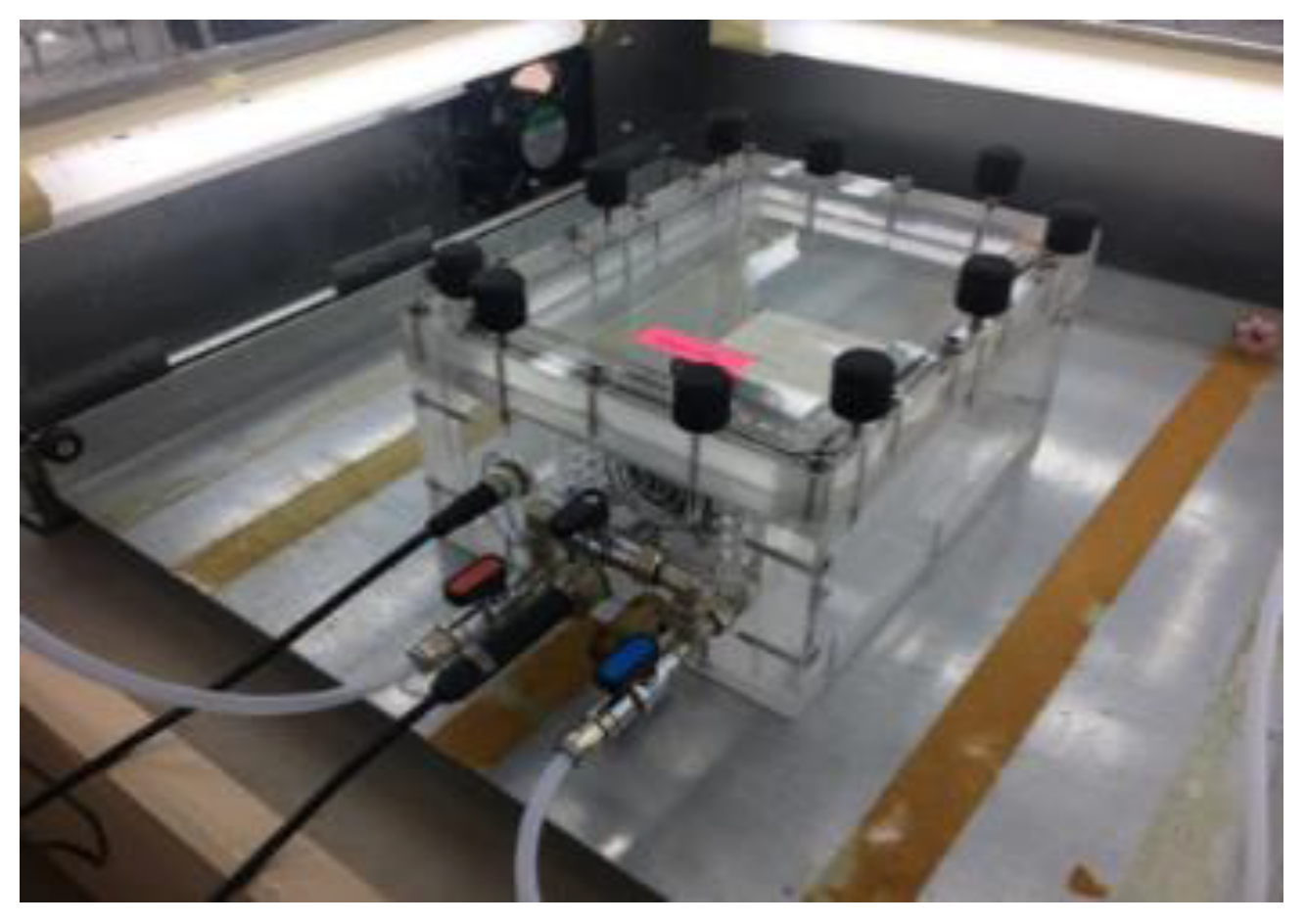
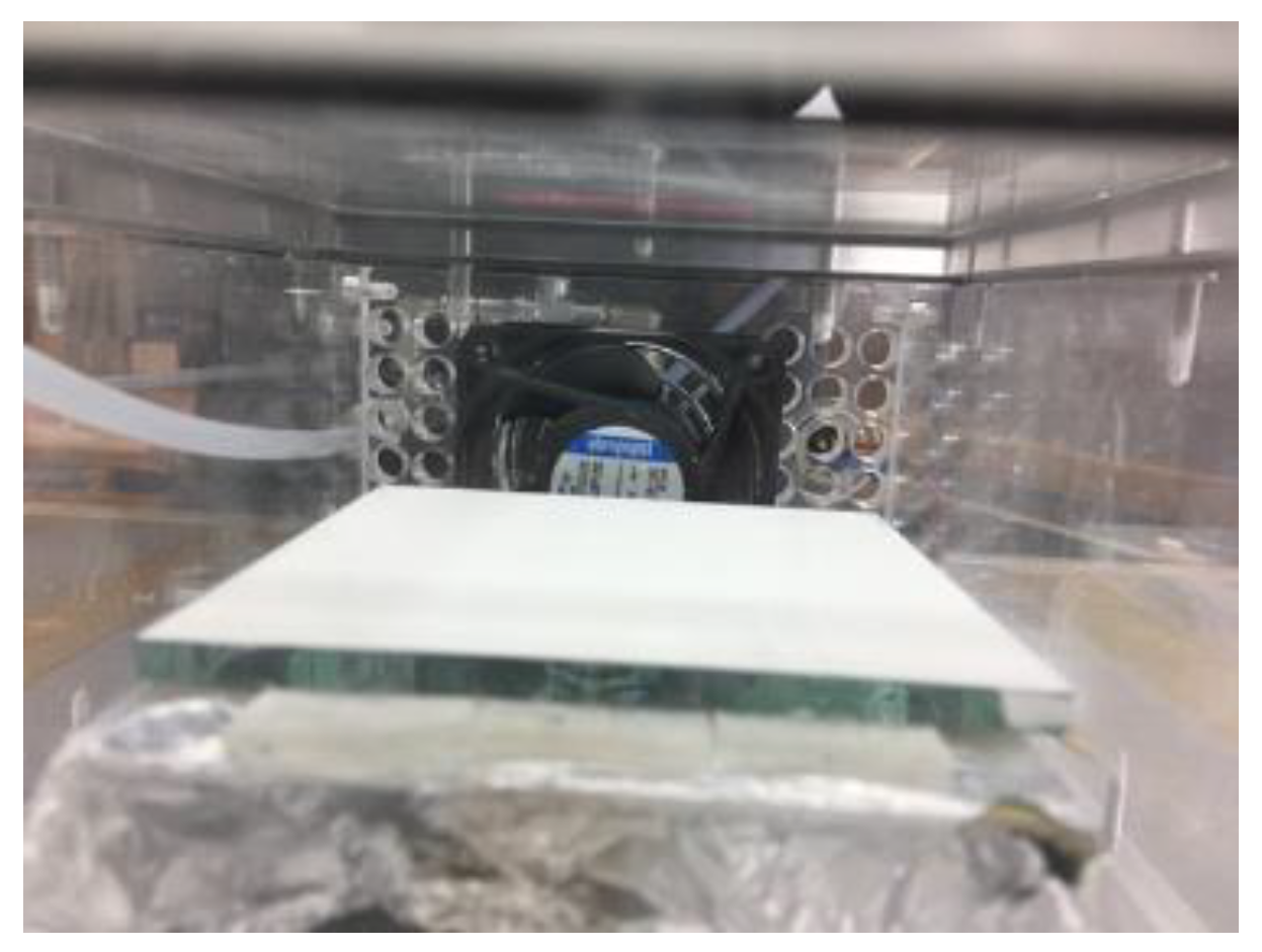
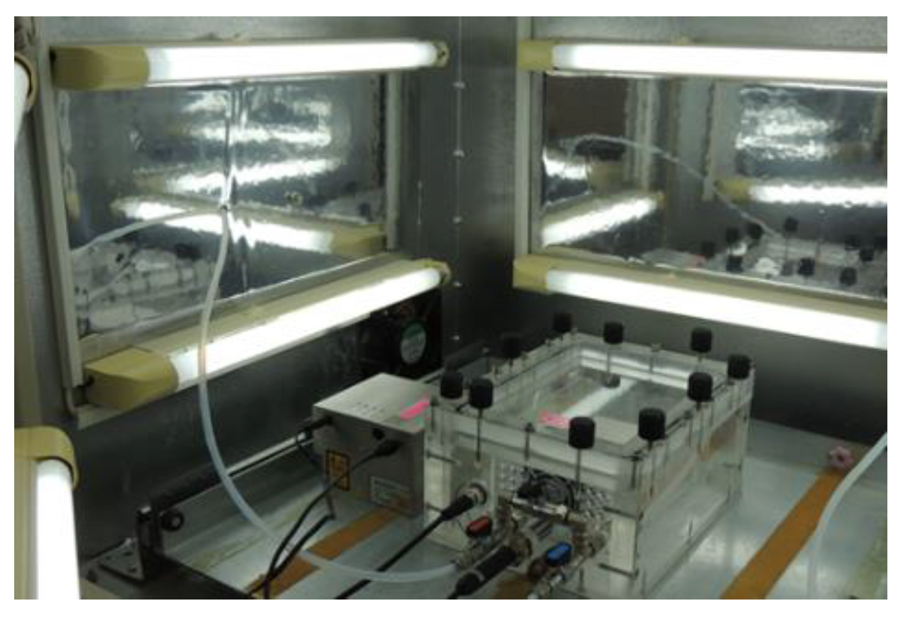
2.4. Photocatalytic Evaluation in Terms of IAQ Improvement_Lab-Scale

The applied experimental methodology was based on EN 16980-1:2021 [42]. The photocatalytic effect of the optimized material was studied in an in-house continuous-flux photocatalytic reactor system (Figure 1), which consists of (a) a gas transfer and mixing unit in order to adjust the concentration and humidity levels; (b) the photocatalytic reactor main body (Figure 2 and Figure 3) made of special plastic so that radiation intensity and wavelength of the radiation are not affected; (c) UV irradiation system Omicron FSLED lamps, LASERAGE FSLED.365.10_10 (Figure 4); (d) the visible irradiation source, which consists of 10 commercial fluorescent lamps (PHILIPS FSL YZ15RR26), which emit across the visible spectrum (Figure 5), and the geometry of the system is such that uniform illumination of the sample surface is ensured; and (e) a NOx (Horiba) and VOC (SYNSPEC GC 955) analyzer connected with the reactor for continuous monitoring of the pollutant concentration. Furthermore, in order to ensure optimum mixing of atmospheric pollutants in the reactor, a fan is installed inside the chamber, while its intensity is adjusted externally to ensure the stability of the experimental conditions throughout the experiments. The NO concentration is set to (0.5 ± 0.05) ppmv, while the relative humidity is set to 40 ± 5%.

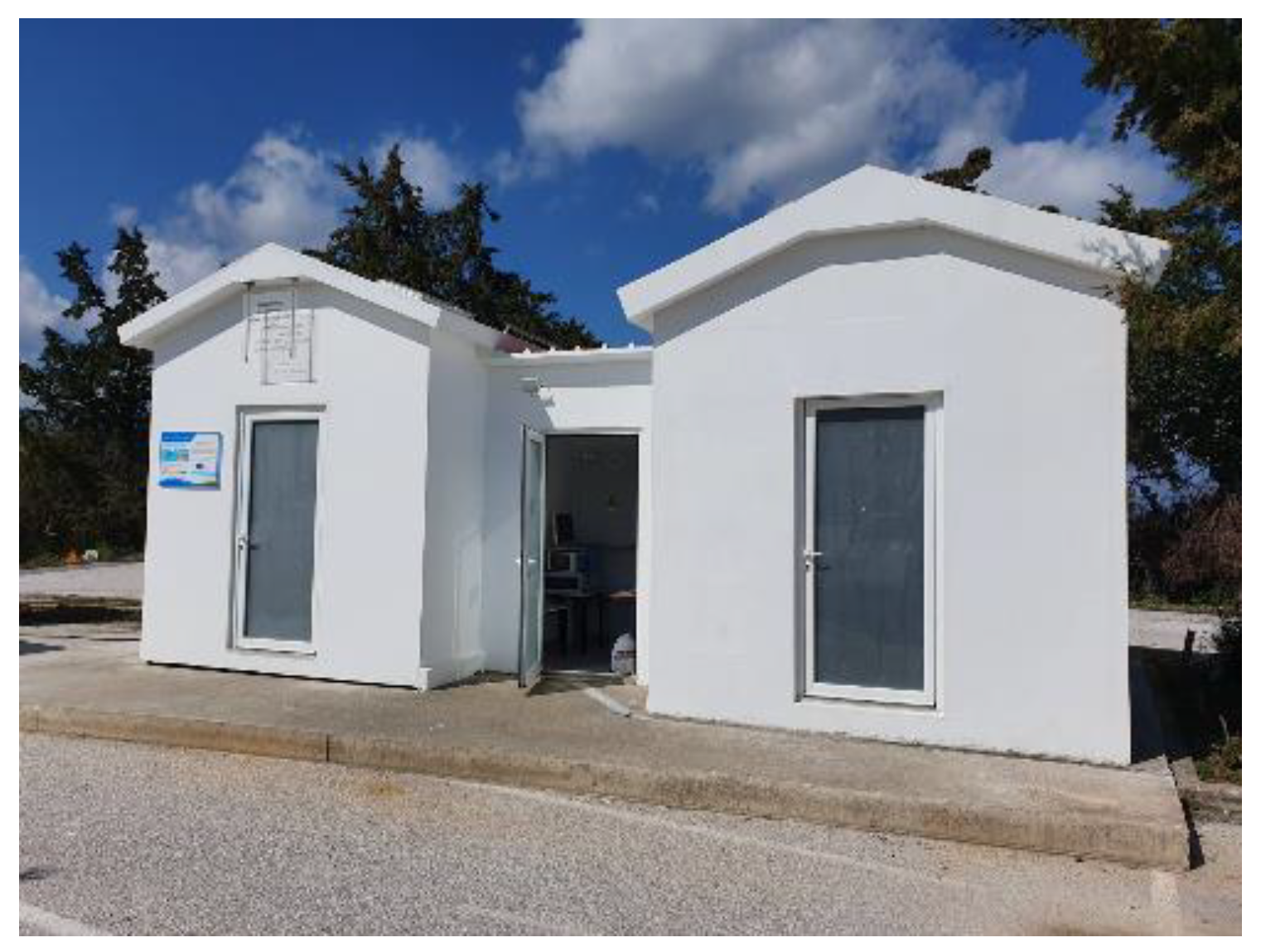
2.5. Photocatalytic Evaluation in Terms of IAQ Improvement_Real-Scale

Real-scale applications of the VISIONS photo-paints (organic and inorganic) were implemented in order to estimate their effectiveness to degrade air pollutants. The application took place in the Demo Houses (Figure 6), which are located on the premises of FORTH in Crete, which with the high-end installation and processing equipment comprise a unique European facility. The VISIONS photo-paints were applied on the surface of the interior area in one of the Demo Rooms (ceiling and walls: approx. 40 m2), the so-called “green room”. The other room was painted with conventional paint in order to be considered as a reference: the “conventional room”. Both rooms were equipped with 8 lamps (Philips 1200 mm, 18watt, LED Ecofit), which emit in visible spectra, and the light intensity on the walls was measured as 10.1 Btu/ft2 h up to 11.3 Btu/ft2 h (Figure 7). The two rooms are separated by a control room where the monitoring equipment coupled with data loggers (NOx, O3, and BTEX analyzers; temperature; RH%; and light intensity) was placed (Figure 8).
The methodological approach to estimate the photocatalytic efficiency of VISIONS photo-paint was as follows:
First approach
Both green (VISIONS paint) and conventional rooms were fed with equal amounts of pollutants and were illuminated using the same lamp system. Continuous monitoring of NOx and VOCs (toluene) was applied in both rooms and the pollutant degradation was determined after 1 h.
Second approach
The “green” (VISIONS paint) room was fed with air pollutants (NO, toluene) without illumination. After stabilizing the pollutant concentration in the room, the elimination of pollutants was calculated after 1 h without illumination. The test was repeated with illumination and the difference in the elimination rates represents the photocatalytic degradation of the pollutants.

2.6. Photocatalytic Evaluation in Terms of Energy Saving_Real-Scale

The energy saving calculation approach was based on the ventilation rate because of the photocatalytic paint use. Natural ventilation in combination with mechanical ventilation according to special weather conditions provides energy efficiency along with thermal comfort for the users [44]. The complicated issue of energy performance along with indoor air quality targets can be accomplished with the balanced operation of ventilation systems in cooperation with heating and cooling system as well as renewable energy system applications. With this way, not only the energy upgrade is ensured but also the reduced greenhouse gas emissions [45]. In this line of approach, activities undertaken for the evaluation of the Demo Houses in terms of energy performance and thermal comfort are specified. First of all, generic and specific pieces of information have been defined such as location, orientation, and shading from adjacent objects. The typological and geometrical data of Demo Houses have been registered. The building materials’ thermal and physical properties (λ and U value, absorptivity, emissivity of the coatings, or otherwise commercial names of materials used), the installed air conditioning equipment (type, capacity, EER and COP if available), and the lighting systems and controls are defined. According to the input data and the design and operational features of Demo Houses, the measurement plan has been defined. Three basic scenarios have been studied in Design Builder. More specifically, scenario 1 referred to the conventional Demo Room without the photocatalytic paint and scenarios 2 and 3 considered the green Demo Room in which the photocatalytic paint has been implemented. The results consider the energy consumption in the winter period as well as in the summer period. The parameter related to the photocatalysis use is the ventilation rate. The photocatalysis proved to help the indoor air quality and thus reduces the need for ventilation and therefore the energy consumption related to the ventilation process.

3. Results

3.1. Physical and Chemical Properties

To identify the most efficient and cost-effective synthetic method yielding photoactive powders, we synthesized doped titanium dioxide powders using various synthetic procedures. In order to find the best synthetic procedure, which will be easy, cost-effective, and lead to photoactive powders, we prepared doped titanium dioxide powders with different synthetic procedures. Undoped and metal-doped TiO2 powders are prepared by a modified sol–gel method according to which the photocatalyst can be obtained by precipitating titanium dioxide with different dopants (such as Mn-, Co-, Cu-, Ni-, Fe-, and Al-). The XRD patterns of undoped titanium dioxide in different synthetic procedures based on ammonia synthesis and alkali-based synthesis are shown in Figure 9a. In the ammonia-based synthesis, the resulting powder exhibits only the anatase phase in comparison with the alkali-based synthesis, which displays a mixed-phase composition.
XRD patterns of pure TiO2 and Mn-, Co-, Cu-, Ni-, Fe-, and Al-doped TiO2 are displayed in Figure 9b. The anatase phase is shown in pure TiO2 and metal-doped TiO2 at an optimum dopant concentration (0.04 %wt) except Ni-doped TiO2. The characteristic peaks indicating the presence of the anatase phase are observed at 2θ values of 25.3°, 37.6°, 48.2°, 53.9°, 54.8°, 62.7°, and 75.2°. These peaks correspond with the crystallographic planes (101), (004), (200), (105), (211), (204), and (215) of anatase, respectively. Moreover, no obvious diffraction peaks attributed to metal or metal oxides (such as MnO2, Co3O4, CuO, Fe2O3, and Al2O3) were observed in those samples, confirming the purity of synthetized powders. The metal ions were probably integrated into either the interstitial positions or substitution sites within the crystalline structure of TiO2.
Among these dopants, the Fe-doped TiO2 demonstrated the most promising photocatalytic behavior. Consequently, we directed our efforts towards optimizing its performance. Then, our subsequent efforts involved attempts to optimize and control the particle size of the iron-doped titanium. In Figure 10a, the XRD patterns before and after the ball milling process are displayed. The peak shown at 25.3° is related to crystal plane 101 of the anatase phase. From the diagram, the significant decrease in grain size from 29.9 nm to 19.4 nm is clear, alongside a change in the intensity of the main crystal plane. The SEM images of Fe-doped TiO2 before and after milling are depicted in Figure 10c,d. Figure 10c shows a relatively small number of small agglomerates (1–3 µm) along with large agglomerates between 10 and 70 µm. The agglomerates were composed of nanosized particles (below 100 nm).
UV–VIS absorption as a function of wavelength for VISION powder is shown in Figure 10b. The incorporation of the Fe into TiO2 resulted in the shift of the absorption edge to the visible light region (400–800 nm). The extension of the absorption spectra of Fe-doped TiO2 into the visible light region was achieved by modifying the electronic energy band structure of TiO2 through the introduction of doped Fe+3 ions. Despite enhancing the spectral response into the visible region, the introduction of iron may present challenges such as thermal instability affecting the anatase phase, potential blocking of reaction sites, and increased charge recombination at the metal sites. (The extension of the spectral response into the visible region after the incorporation of iron improves the overall photocatalytic activity despite certain issues that may occur like thermal instability to the anatase phase, blocking of reaction sites, and promoted charge recombination at metal sites.)
The physicochemical properties of the photo-paint are listed in Table 1. The measured values are typical for an indoor emulsion architectural paint, and although VISIONS photo-powder was used at 20% w/w, powder behaved as a Titanium Oxide white pigment. Both the organic and the inorganic paints were designed to have the same physicochemical properties with the commercial non-photocatalytic paints. To that end, the paints formulated with the process described in 2.2.2 as well as with the use of Ti Pure 902+ Titanium Oxide white pigment had identical physicochemical properties.

3.2. Laboratory Photocatalytic Performance of the Photo-Powder

The lab-scale tests provide information on the elimination of air pollutants due to both photolysis and photocatalysis on the photo-powder. To that end, experiments in the absence of the photocatalytic powder were initially performed in order to estimate background contribution. The photocatalytic effect is calculated by the subtraction of the side-effect pollutant elimination during the photocatalytic experiments. More specifically, the reactor was fed with NO and toluene in the absence of the photocatalyst with and without irradiation, respectively. Afterwards, the experiments were repeated but with the presence of the photocatalyst.
Figure 11a,b present the elimination of NO and toluene under the irradiation of the photo-paint from Vis light. It is observed that by Time 30 (start of irradiation), a significant decrease in NO concentration was present while a less sharp but also important decrease is shown for toluene. The latter demonstrate the instant response and the significant efficiency of the photo-paint to degrade both pollutants.
Side effects of pollutant removal such as adsorption on the chamber’s walls and photolysis were calculated and results showed that both these mechanisms did not have significant contribution to pollutant removal during the lab-scale experiments.
The evaluation of the photocatalytic activity was performed by calculating photocatalytic yield (% n, Equation (3)), photodegradation rate (r, Equation (4)), and deposition velocity (Vd, Equation (5)). The corresponding equations were used for toluene. Results in Table 2 are very promising and show a very active photocatalytic powder in terms of air pollutant degradation.
%   η N O t o t a l = C N O I N C N O O U T ,     l i g h t C N O I N × 100
where C N O I N is the concentration of NO at the reactor inlet.
C N O O U T ,   l i g h t is the concentration of NO at the reactor outlet under stable conditions with irradiation (lamp on).
The photocatalytic rate of yield of the material is calculated by the formula below (Equation (3)) and expressed in μgm−2 s−1:
r N O p h o t o = 613 F S ( η NO total ( 1 η NO total ) η NO dark ( 1 η NO dark ) )
where F is the gas flow (m3 h−1); S is the area of the test surface (m2).
The deposition velocity (Vd) was calculated as follows:
Vd = r NO/Cin NO
The photocatalytic rate provides a more accurate measure of the photo-paint activity as it is taking under consideration not only the final and the initial concentration of the pollutant but also the sample’s surface area and the irradiation time. To that end, compared with the % photocatalytic degradation, it is expressed as μg of converted NO/toluene per m2 of material per second of irradiation. As mentioned before, the losses in the system are minimal, and as a consequence, the fraction η N O d a r k ( 1 η N O d a r k ) is zero.
Figure 11a,b present NO and toluene concentration trends during the photocatalytic tests. After pollutant input into the reactor, an equilibrium phase of 30 min is established. By the time the irradiation starts, a sharp NO elimination is observed while a significant but less intense reduction in toluene concentration is also shown. Then, it was stabilized for approximately 1 h and by the time the irradiation stopped, it was increased to the initial concentration level. Although the degradation efficiency of toluene is lower than NO, the obtained results from both NO and toluene laboratory tests could be characterized as very promising, as they could have significant effects in the improvement of IAQ.

3.3. Real-Scale Photocatalytic Performance of the Photo-Paints in Air Pollutant Degradation

The depollution efficiency of both organic and inorganic paint under the real-scale application was calculated by the difference in the concentration levels of NO and toluene in the two rooms of the Demo Houses: the “green” and the “reference” rooms (Table 3). As it was expected from previous studies [50,51,52], real-scale applications of photo-paints show lower photocatalytic performance in terms of air pollutant elimination than in the lab-scale tests of photo-powder. The mixture of photo-powder in the paint matrix and the controlled environment of the laboratory versus the more complex and polyparametric environment of a real-scale application are the main reasons for the lower values observed for the photocatalytic parameters of the paints. However, they provide a more realistic approach of the photocatalytic efficiency of the photo-paints to improve IAQ through in situ air pollutant photocatalytic degradation.
Based on the above-described methodology (2.5) and equations (3.2), it was calculated that by activating the photocatalytic building material (turn on the Vis light), the pollution level in the ‘green room’ was reduced up to 61.7% for the organic paint and 36.8% for the inorganic paint, while in the conventional one, it was up to 24.6%. The corresponding values for toluene were significantly lower (up to 5.8% for the organic paint while for the inorganic one, the elimination was negligible). All side effects (adsorption on walls, photolysis, photocatalysis, etc.) were also estimated. In the scenario that the windows were not covered and sun light (UV light) irradiated the room, the reductions in NO were even higher, up to 70.1% (Figure 12) for the organic paint.
In order to normalize the initial concentrations of the experiments (as there were differences), the ln(Ct/Co), where Ct is the initial concentration and Co is the average concentration of the NO before the lamps were turned on for the experiments, was calculated. Figure 13 presents the ln(Ct/Co) vs. time during the conventional tests (1C, 2C, 3C) and the photocatalytic (4P, 5P, 6P) experiments. The significant reduction in NO during photocatalytic tests is clearly presented.

3.4. Real-Scale Photocatalytic Performance of the Photo-Paints in Energy Saving

The simulation results in Demo Houses depicted an energy reduction at about 7%. The detailed analysis of the approach, the scenarios selected, and the different energy results per process are presented below. In these scenarios, the energy reduction was compared to the conventional scenario (without photocatalysis) based on the ventilation rate reduction, which was determined by the occupancy (Table 4).
In the second scenario (Table 5), a simulation was carried out with the photocatalytic approach operation, assuming people density reduced by 20%. The target was to connect photocatalytic paint use with energy consumption. The parameter affected by photocatalytic paint is the ventilation rate due to emission reduction.
As it was expected in the second scenario where the ventilation rate has decreased, the energy consumption was affected and reduced. In case the ventilation rate reduces more, the energy reduction is also more noticeable. More specifically and based on case 3 where the photocatalytic impact is higher, the results are presented in Table 6.
There is a correlation of ventilation rates and photocatalysis (ventilation is related to energy consumption). The simulations determined about 5–7% energy reduction compared to the conventional scenario (without photocatalysis) because of the ventilation rate reduction. The energy parameter related to photocatalysis as already analyzed above is the ventilation rate. The photocatalysis helps the indoor air quality and thus reduces the need for extra ventilation. The reduction in ventilation rates leads not only to reduced energy consumption for ventilation, but also decreased energy consumption for heating and cooling due to decreased ventilation heat losses and gains, respectively. So based on measurements, the air pollutant concentration was determined and in order to reach these levels of reduction for the air pollutants, the use of mechanical ventilation was also measured. Based on the measurements at the Demo Houses, the ventilation rate was determined and then with the use of Design Builder, the ventilation rate input was entered in relation to the occupancy. As of now, it has been defined that the emission concentration has been reduced because of the photocatalysis. The next set of simulations will collate the reduction in the ventilation rate based on the emission reduction in order to validate the percentage of energy reduction because of photocatalysis. It is interesting to point out the energy as well as the CO2 emission reduction in connection to users’ presence, ventilation rate, and photocatalysis implementation. The effect of photocatalysis in the emission reduction is declared based on measurements in Demo Houses. The defined emission reduction and the need for less ventilation are the key issues for the reduction in energy consumption.

4. Discussion

The improvement of IAQ using photocatalytic paints (organic and/or inorganic) under visible light with parallel energy saving is feasible. Based on the outcome of real-scale applications, it was proven that NO and VOCs (toluene) could be effectively removed by the photocatalytic paint, although toluene is shown with less photocatalytic sensitivity than NO under the same photocatalytic process. The latter could be explained by the higher adsorption of NO by the alkaline constituents of the paint due to its acidic property, which significantly increases NO reaction potential with HOx radicals. It is worthwhile to note that HOx radicals are the dominant oxidants in a photocatalytic reaction [50,51]. On the other hand, toluene is absorbed better in less hydrophilic TiO2 surfaces than a hydroxylated one [52]. It is clear that the diffusion degree of each pollutant in the paint matrix significantly affects its photocatalytic activity. A photocatalytic reaction is promoted by a more efficient adsorption of the pollutant molecules at the catalyst surface. As far as the energy consumption is concerned, it was calculated that the reduced usage of the ventilation system due to the improved IAQ results in energy saving of more than 7% in the current case study of Demo Houses, promising more optimistic rates of reduction in real-world applications. The simulations proved the strong correlation of the ventilation process and the reduction in the ventilation rate because of the photocatalysis.
Laboratory tests of the powder showed a higher degradation rate of pollutants compared with the corresponding values of the real-scale application of the paint. The latter is expected for two reasons. Mixing photo-powder in a paint matrix decreases its active catalytic surface. The paint matrix itself might impede the diffusion of pollutants to the embedded photo-powder particles, affecting the efficiency of the catalytic process by reducing the contact between the pollutants and the active sites. In addition, the paint matrix might encapsulate the photo-powder particles, limiting their exposure to the environment, and preventing the interaction between the pollutants and the active catalytic sites on the powder’s surface. Furthermore, factors like temperature, humidity, airflow, and other environmental variables can significantly impact the performance of the photo-powder in degrading pollutants. Although the polyparametric and complex real-world environment results in lower photocatalytic efficiency values of the paint compared to lab-scale tests, it provides a more realistic characterization of the photocatalytic paints’ efficiency to improve IAQ. There are many cases in the literature of photocatalytic building materials, which showed very promising results during lab-scale tests, but the latter were not proven when applied to real-world conditions. To that end, it is very important to prove the efficiency of a material under real-scale conditions, due to the elimination of the photocatalytic character when upscaling in a more complex environment. Additionally, in most cases, TiO2, under UV irradiance, oxidizes not only the air pollutants on the photo-paint surface, but also their organic components. To that end, it is crucial to give special attention to the formulation of the paints (especially inorganic), which will be activated under Vis light. In the current study, the inorganic paint was produced with the same ingredients as the organic formulation except the binder. Instead of using organic polymer emulsion, a water–glass solution was used (potassium silicate). To that end, the formation and emission of by-products during the photocatalysis are eliminated while the mechanical properties of the photo-paint remain constant. More specifically, almost one year after the photo-paint application, surface damages have not been observed. However, the latter should be studied intensively through measurements of both the mechanical properties and the emissions of possible by-products in a future study as it is not under the scope of the current work. As a continuation of the current study, the photocatalytic paint is scheduled to be applied in real-world conditions (building of Hellenic Naval Academy). Beyond the measurements of its efficiency to improve IAQ and achieve energy savings, mathematical models (CFD) will be applied in order to simulate the photocatalytic processes and be able to assess the real-life effects of the intervention. In addition, life cycle assessment (LCA) of the produced photocatalytic paint will be presented [53].

5. Conclusions

The current study deals with the improvement of IAQ and energy consumption in buildings through the application of an innovative photocatalytic paint. The synthesis route of the photo-powder, mixing procedures with the paint matrix, and real-scale application are described. The main outcomes of the above procedures are summarized as follows:
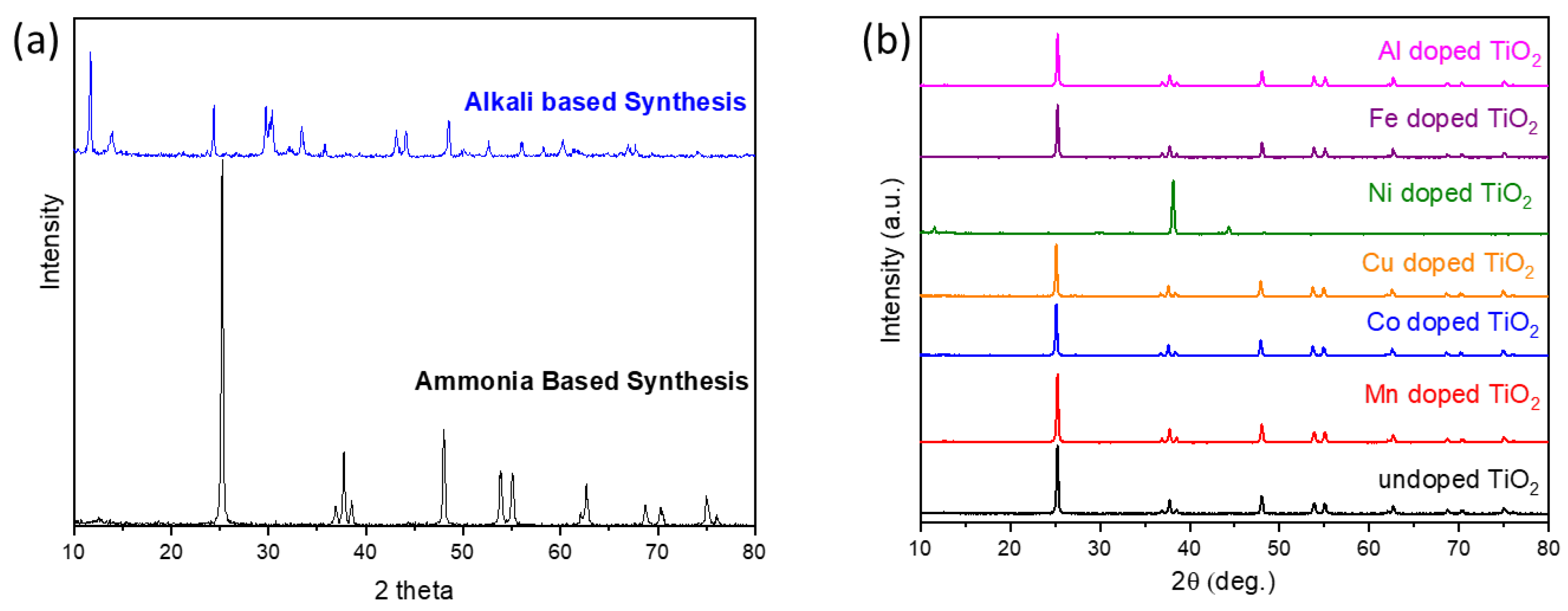
  • Fe-doped TiO2 was prepared successfully using an easy and cost-effective co-precipitation process. In the case of Fe, doping shifted the optical absorption edge to the visible region significantly.
  • The photocatalytic paint formulation has the same physicochemical and application characteristics as the commodity paints while presenting significant photocatalytic properties in terms of air pollutant elimination under real-scale application.
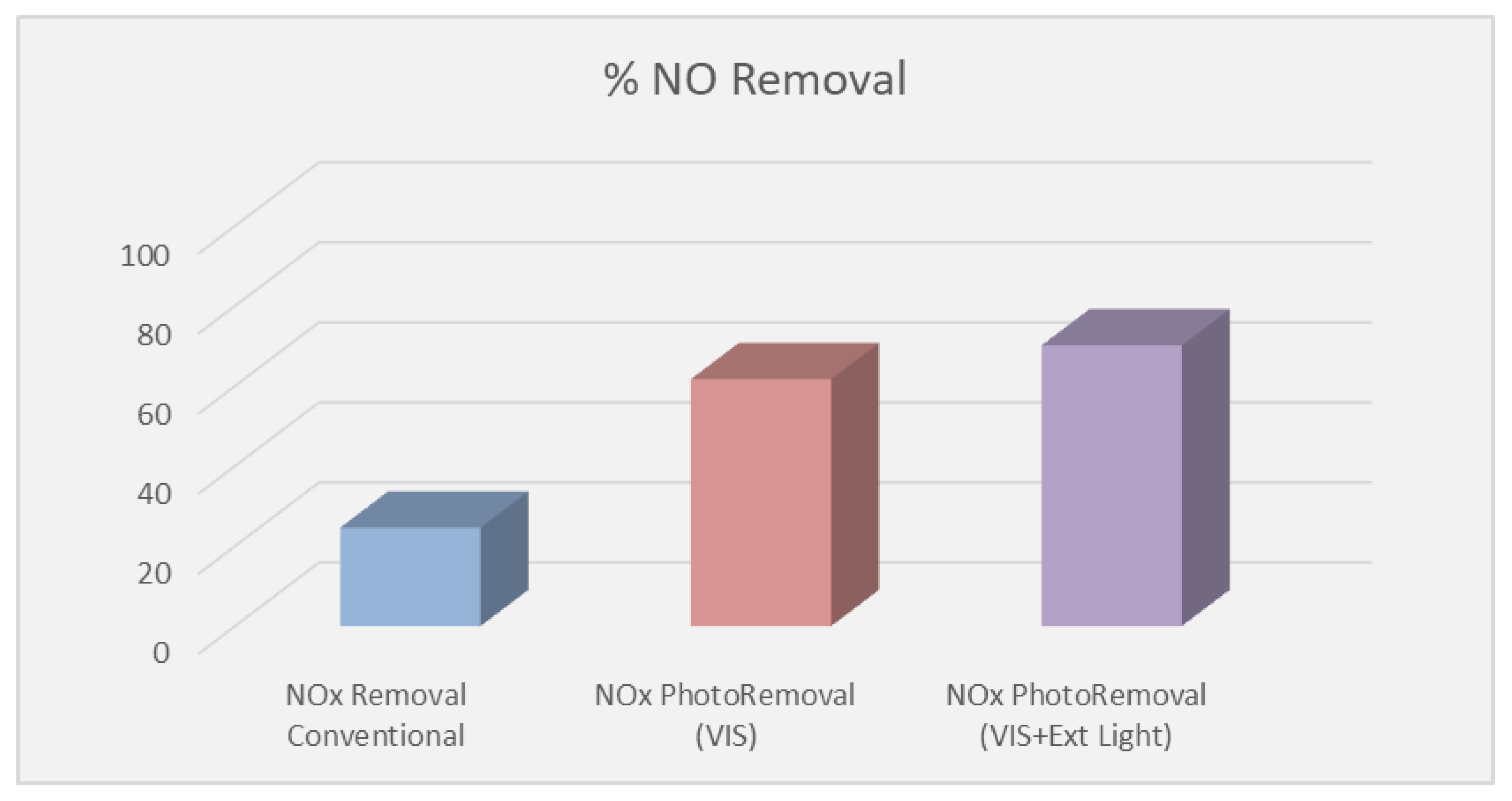
  • The real-scale application of the photo-paint is shown with lower photocatalytic performance than the corresponding photo-powder, which was tested under a laboratory scale. The reason for the lower activity of the paint compared with powder is the polyparametric conditions (such as humidity, temperature, initial concentration, etc.) in the real-scale application.
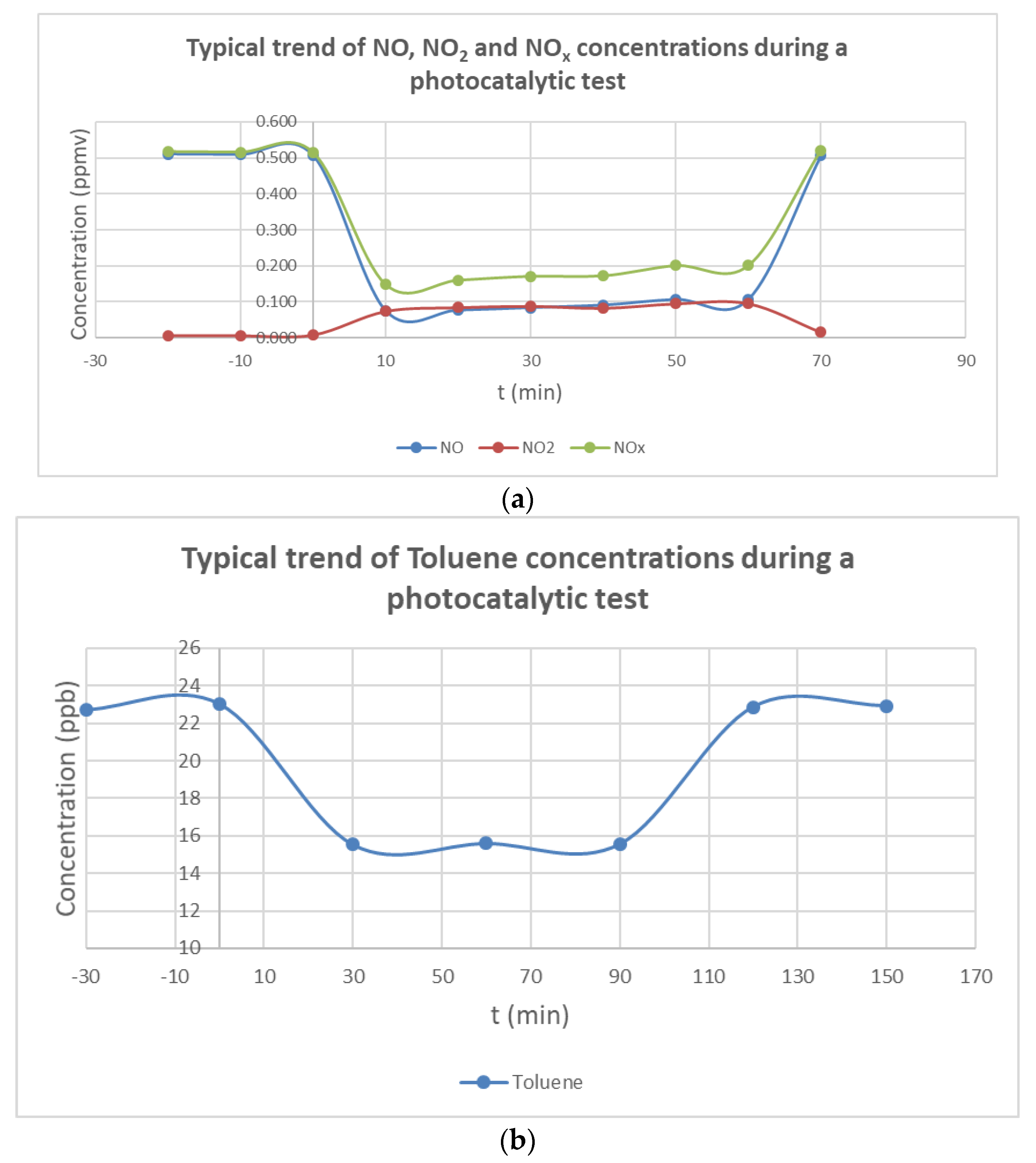
  • The ability of both organic and inorganic paints to photocatalytically remove NO was higher than toluene. The chemical structure of the pollutant plays a significant role during the oxidation reaction with the photocatalyst. Although the removal rate of toluene was lower than NO, it was very promising for IAQ applications.
  • As a result of IAQ improvement, which was obtained from the application of the photocatalytic paint, the ventilation rate was reduced. Accordingly, the energy consumption in the “green” room was reduced by more than 7% compared to the “conventional” room.
  • Although a real-scale application was conducted in the frame of the current work (Demo Houses), the latter was performed under controlled conditions (initial pollutant concentration, light intensity, access restrictions, etc.). To that end, there is a need for real-world building applications in order to prove the efficiency of photocatalytic paints to improve IAQ on-site. The latter is ongoing in the Hellenic Naval Academy and the results will be presented in a future manuscript.

Author Contributions

Conceptualization, T.M., V.B. and E.G.; Data curation, T.M., P.P., E.S., E.G. and G.C.; Investigation, E.G., P.P., E.S., V.B., G.K., G.C., A.P., K.T. and A.N.; Methodology, E.G., A.P., G.K., T.M., V.B., K.T., E.G., A.P. and A.N.; Project administration, T.M.; Writing—original draft, T.M.; Writing—review and editing, T.M., V.B., E.G., K.T. and A.P. All authors have read and agreed to the published version of the manuscript.

Funding

This work was supported by LIFE VISIONS project (LIFE19 ENV/GR/000100), with the contribution of the LIFE Programme of the European Union. This work reflects only the authors’ view and CINEA is not responsible for any use that may be made of the information it contains.

Institutional Review Board Statement

Not applicable.

Informed Consent Statement

Not applicable.

Data Availability Statement

Dataset available on request from the authors. The raw data supporting the conclusions of this article will be made available by the authors on request.

Conflicts of Interest

Authors Konstantinos Theodorou and Aristotelis Nikolakopoulos were employed by the company VITEX S.A. The remaining authors declare that the re-search was conducted in the absence of any commercial or financial relationships that could be construed as a potential conflict of interest.

References

  1. Mamaghani, A.H.; Haghighat, F.; Lee, C.-S. Photocatalytic Oxidation Technology for Indoor Environment Air Purification: The State-of-the-Art. Appl. Catal. B Environ. 2017, 203, 247–269. [Google Scholar] [CrossRef]
  2. Zhong, L.; Haghighat, F. Photocatalytic Air Cleaners and Materials Technologies—Abilities and Limitations. Build. Environ. 2015, 91, 191–203. [Google Scholar] [CrossRef]
  3. Zhong, L.; Haghighat, F.; Blondeau, P.; Kozinski, J. Modeling and Physical Interpretation of Photocatalytic Oxidation Efficiency in Indoor Air Applications. Build. Environ. 2010, 45, 2689–2697. [Google Scholar] [CrossRef]
  4. Salvadores, F.; Reli, M.; Alfano, O.M.; Kočí, K.; Ballari, M.D.L.M. Efficiencies Evaluation of Photocatalytic Paints Under Indoor and Outdoor Air Conditions. Front. Chem. 2020, 8, 551710. [Google Scholar] [CrossRef] [PubMed]
  5. 2021 Global Status Report for Buildings and Construction Towards a Zero-Emission Efficient and Resilient Buildings and Construction Sector.Pdf. Available online: https://www.google.com/url?sa=t&source=web&rct=j&opi=89978449&url=https://globalabc.org/sites/default/files/2021-10/GABC_Buildings-GSR-2021_BOOK.pdf&ved=2ahUKEwiExM6T8Y6HAxVus1YBHc3oBKUQFnoECBEQAQ&usg=AOvVaw1pfV3gOxQ4C3_NXO-s0UPr (accessed on 14 March 2024).
  6. BPIE. Indoor Air Quality, Thermal Comfort and Daylight. Analysis of Residential Building Regulations in Eight EU Member States.Pdf. Available online: https://www.google.com/url?sa=t&source=web&rct=j&opi=89978449&url=https://www.bpie.eu/wp-content/uploads/2015/10/BPIE_executive_briefing_IAQ2015.pdf&ved=2ahUKEwj3sNnA8Y6HAxVKqFYBHQ2KDGkQFnoECA4QAQ&usg=AOvVaw35l0s9gEh-wXa5nNhmJLh5 (accessed on 14 March 2024).
  7. Shayegan, Z.; Bahri, M.; Haghighat, F. A Review on an Emerging Solution to Improve Indoor Air Quality: Application of Passive Removal Materials. Build. Environ. 2022, 219, 109228. [Google Scholar] [CrossRef]
  8. Directive 2010/31/EU, Off. J. Eur. Union, Vol. L153/13, No. 18.6.2010.Pdf. Available online: https://www.google.com/url?sa=t&source=web&rct=j&opi=89978449&url=https://eur-lex.europa.eu/LexUriServ/LexUriServ.do%3Furi%3DOJ:L:2010:153:0013:0035:EN:PDF&ved=2ahUKEwiLsq7d8Y6HAxU7slYBHS6vCTMQFnoECBEQAQ&usg=AOvVaw0pOZGXaqo5VZyusosxfeop (accessed on 14 March 2024).
  9. Regulation EU No 305/2011 of the European Parliament and of the Council of 9 March 2011 Laying down Harmonised Conditions for the Marketing of Construction Products and Repealing Council Directive 89/106/EEC Text with EE.Pdf. Available online: https://www.google.com/url?sa=t&source=web&rct=j&opi=89978449&url=https://eur-lex.europa.eu/LexUriServ/LexUriServ.do%3Furi%3DOJ:L:2011:088:0005:0043:EN:PDF&ved=2ahUKEwi8rbD38Y6HAxXSslYBHeg0C5IQFnoECBwQAQ&usg=AOvVaw1LrzHJNHg4WJujhH3i-TCe (accessed on 14 March 2024).
  10. Águia, C.; Ângelo, J.; Madeira, L.M.; Mendes, A. Influence of Photocatalytic Paint Components on the Photoactivity of P25 towards NO Abatement. Catal. Today 2010, 151, 77–83. [Google Scholar] [CrossRef]
  11. Ao, C.H.; Lee, S.C. Indoor Air Purification by Photocatalyst TiO2 Immobilized on an Activated Carbon Filter Installed in an Air Cleaner. Chem. Eng. Sci. 2005, 60, 103–109. [Google Scholar] [CrossRef]
  12. Morales-Torres, S.; Pastrana-Martínez, L.M.; Figueiredo, J.L.; Faria, J.L.; Silva, A.M.T. Design of Graphene-Based TiO2 Photocatalysts—A Review. Environ. Sci. Pollut. Res. 2012, 19, 3676–3687. [Google Scholar] [CrossRef] [PubMed]
  13. Jansson, I.; Suárez, S.; Garcia-Garcia, F.J.; Sánchez, B. Zeolite–TiO2 Hybrid Composites for Pollutant Degradation in Gas Phase. Appl. Catal. B Environ. 2015, 178, 100–107. [Google Scholar] [CrossRef]
  14. Wang, Q.; Zhu, S.; Zhao, S.; Li, C.; Wang, R.; Cao, D.; Liu, G. Construction of Bi-Assisted Modified CdS/TiO2 Nanotube Arrays with Ternary S-Scheme Heterojunction for Photocatalytic Wastewater Treatment and Hydrogen Production. Fuel 2022, 322, 124163. [Google Scholar] [CrossRef]
  15. Wang, Q.; Zhao, S.; Zhao, Y.; Deng, Y.; Yang, W.; Ye, Y.; Wang, K. Construction of Z-Scheme Bi2O3/CeO2 Heterojunction for Enhanced Photocatalytic Capacity of TiO2 NTs. Spectrochim. Acta Part A Mol. Biomol. Spectrosc. 2024, 304, 123405. [Google Scholar] [CrossRef] [PubMed]
  16. Jia, Y.; Liu, P.; Wang, Q.; Wu, Y.; Cao, D.; Qiao, Q.-A. Construction of Bi2S3-BiOBr Nanosheets on TiO2 NTA as the Effective Photocatalysts: Pollutant Removal, Photoelectric Conversion and Hydrogen Generation. J. Colloid Interface Sci. 2021, 585, 459–469. [Google Scholar] [CrossRef] [PubMed]
  17. Wang, Q.; Zhao, Y.; Zhang, Z.; Liao, S.; Deng, Y.; Wang, X.; Ye, Q.; Wang, K. Hydrothermal Preparation of Sn3O4/TiO2 Nanotube Arrays as Effective Photocatalysts for Boosting Photocatalytic Dye Degradation and Hydrogen Production. Ceram. Int. 2023, 49, 5977–5985. [Google Scholar] [CrossRef]
  18. Wang, Q.; Li, H.; Yu, X.; Jia, Y.; Chang, Y.; Gao, S. Morphology Regulated Bi2WO6 Nanoparticles on TiO2 Nanotubes by Solvothermal Sb3+ Doping as Effective Photocatalysts for Wastewater Treatment. Electrochim. Acta 2020, 330, 135167. [Google Scholar] [CrossRef]
  19. Giosuè, C.; Belli, A.; Mobili, A.; Citterio, B.; Biavasco, F.; Ruello, M.; Tittarelli, F. Improving the Impact of Commercial Paint on Indoor Air Quality by Using Highly Porous Fillers. Buildings 2017, 7, 110. [Google Scholar] [CrossRef]
  20. Morin, J.; Gandolfo, A.; Temime-Roussel, B.; Strekowski, R.; Brochard, G.; Bergé, V.; Gligorovski, S.; Wortham, H. Application of a Mineral Binder to Reduce VOC Emissions from Indoor Photocatalytic Paints. Build. Environ. 2019, 156, 225–232. [Google Scholar] [CrossRef]
  21. Gandolfo, A.; Marque, S.; Temime-Roussel, B.; Gemayel, R.; Wortham, H.; Truffier-Boutry, D.; Bartolomei, V.; Gligorovski, S. Unexpectedly High Levels of Organic Compounds Released by Indoor Photocatalytic Paints. Environ. Sci. Technol. 2018, 52, 11328–11337. [Google Scholar] [CrossRef] [PubMed]
  22. Auvinen, J.; Wirtanen, L. The Influence of Photocatalytic Interior Paints on Indoor Air Quality. Atmos. Environ. 2008, 42, 4101–4112. [Google Scholar] [CrossRef]
  23. Salthammer, T.; Fuhrmann, F. Photocatalytic Surface Reactions on Indoor Wall Paint. Environ. Sci. Technol. 2007, 41, 6573–6578. [Google Scholar] [CrossRef]
  24. Guo, M.-Z. TiO2-Based Self-Compacting Glass Mortar: Comparison of Photocatalytic Nitrogen Oxide Removal and Bacteria Inactivation. Build. Environ. 2012, 53, 1–6. [Google Scholar] [CrossRef]
  25. Mills, A.; Burns, L.; O’Rourke, C.; Elouali, S. Kinetics of the Photocatalysed Oxidation of NO in the ISO 22197 Reactor. J. Photochem. Photobiol. A Chem. 2016, 321, 137–142. [Google Scholar] [CrossRef]
  26. De Melo, J.V.S.; Trichês, G. Evaluation of the Influence of Environmental Conditions on the Efficiency of Photocatalytic Coatings in the Degradation of Nitrogen Oxides (NOx). Build. Environ. 2012, 49, 117–123. [Google Scholar] [CrossRef]
  27. Pirola, C.; Boffito, D.C.; Vitali, S.; Bianchi, C.L. Photocatalytic Coatings for Building Industry: Study of 1 Year of Activity in the NO x Degradation. J. Coat. Technol. Res. 2012, 9, 453–458. [Google Scholar] [CrossRef]
  28. Cárdenas, C.; Tobón, J.I.; García, C.; Vila, J. Functionalized Building Materials: Photocatalytic Abatement of NOx by Cement Pastes Blended with TiO2 Nanoparticles. Constr. Build. Mater. 2012, 36, 820–825. [Google Scholar] [CrossRef]
  29. Suárez, S.; Portela, R.; Hernández-Alonso, M.D.; Sánchez, B. Development of a Versatile Experimental Setup for the Evaluation of the Photocatalytic Properties of Construction Materials under Realistic Outdoor Conditions. Environ. Sci. Pollut. Res. 2014, 21, 11208–11217. [Google Scholar] [CrossRef] [PubMed]
  30. Monteiro, R.A.R. Are TiO2-Based Exterior Paints Useful Catalysts for Gas-Phase Photooxidation Processes? A Case Study on n-Decane Abatement for Air Detoxification. Appl. Catal. B Environ. 2014, 147, 988–999. [Google Scholar] [CrossRef]
  31. Le Bechec, M.; Kinadjian, N.; Ollis, D.; Backov, R.; Lacombe, S. Comparison of Kinetics of Acetone, Heptane and Toluene Photocatalytic Mineralization over TiO2 Microfibers and Quartzel® Mats. Appl. Catal. B Environ. 2015, 179, 78–87. [Google Scholar] [CrossRef]
  32. Huang, H. Efficient Degradation of Gaseous Benzene by VUV Photolysis Combined with Ozone-Assisted Catalytic Oxidation: Performance and Mechanism. Appl. Catal. B Environ. 2016, 186, 62–68. [Google Scholar] [CrossRef]
  33. Antonello, A.; Soliveri, G.; Meroni, D.; Cappelletti, G.; Ardizzone, S. Photocatalytic Remediation of Indoor Pollution by Transparent TiO2 Films. Catal. Today 2014, 230, 35–40. [Google Scholar] [CrossRef]
  34. Pham, T.-D.; Lee, B.-K.; Lee, C.-H. The Advanced Removal of Benzene from Aerosols by Photocatalytic Oxidation and Adsorption of Cu–TiO2/PU under Visible Light Irradiation. Appl. Catal. B Environ. 2016, 182, 172–183. [Google Scholar] [CrossRef]
  35. Dhada, I.; Nagar, P.K.; Sharma, M. Photo-Catalytic Oxidation of Individual and Mixture of Benzene, Toluene and p-Xylene. Int. J. Environ. Sci. Technol. 2016, 13, 39–46. [Google Scholar] [CrossRef]
  36. Dong, F.; Ni, Z.; Li, P.; Wu, Z. A General Method for Type I and Type II G-C3N4/g-C3N4 Metal-Free Isotype Heterostructures with Enhanced Visible Light Photocatalysis. New J. Chem. 2015, 39, 4737–4744. [Google Scholar] [CrossRef]
  37. Li, D.; Haneda, H.; Hishita, S.; Ohashi, N. Visible-Light-Driven N−F−Codoped TiO2 Photocatalysts. 2. Optical Characterization, Photocatalysis, and Potential Application to Air Purification. Chem. Mater. 2005, 17, 2596–2602. [Google Scholar] [CrossRef]
  38. Zhang, Q.; Huang, Y.; Xu, L.; Cao, J.; Ho, W.; Lee, S.C. Visible-Light-Active Plasmonic Ag–SrTiO3 Nanocomposites for the Degradation of NO in Air with High Selectivity. ACS Appl. Mater. Interfaces 2016, 8, 4165–4174. [Google Scholar] [CrossRef] [PubMed]
  39. Kubacka, A.; Colón, G.; Fernández-García, M. Cationic (V, Mo, Nb, W) Doping of TiO2–Anatase: A Real Alternative for Visible Light-Driven Photocatalysts. Catal. Today 2009, 143, 286–292. [Google Scholar] [CrossRef]
  40. Zhong, L.; Brancho, J.J.; Batterman, S.; Bartlett, B.M.; Godwin, C. Experimental and Modeling Study of Visible Light Responsive Photocatalytic Oxidation (PCO) Materials for Toluene Degradation. Appl. Catal. B Environ. 2017, 216, 122–132. [Google Scholar] [CrossRef] [PubMed]
  41. Maggos, T.; Binas, V.; Siaperas, V.; Terzopoulos, A.; Panagopoulos, P.; Kiriakidis, G. A Promising Technological Approach to Improve Indoor Air Quality. Appl. Sci. 2019, 9, 4837. [Google Scholar] [CrossRef]
  42. EN16980-1:2021; Photocatalysis—Continuous Flow Test Methods—Part 1: Determination of the Degradation of Nitric Oxide (NO) in the Air by Photocatalytic Materials. Available online: https://standards.iteh.ai/catalog/standards/cen/e553c4c6-a577-4530-b32b-c9165aba25c3/en-16980-1-2021 (accessed on 4 July 2024).
  43. Binas, V.D.; Sambani, K.; Maggos, T.; Katsanaki, A.; Kiriakidis, G. Synthesis and Photocatalytic Activity of Mn-Doped TiO2 Nanostructured Powders under UV and Visible Light. Appl. Catal. B Environ. 2012, 113–114, 79–86. [Google Scholar] [CrossRef]
  44. Giama, E.; Chantzis, G.; Kontos, S.; Keppas, S.; Poupkou, A.; Liora, N.; Melas, D. Building Energy Simulations Based on Weather Forecast Meteorological Model: The Case of an Institutional Building in Greece. Energies 2022, 16, 191. [Google Scholar] [CrossRef]
  45. Giama, E. Review on Ventilation Systems for Building Applications in Terms of Energy Efficiency and Environmental Impact Assessment. Energies 2021, 15, 98. [Google Scholar] [CrossRef]
  46. ASTM D 562; Standard Test Method for Consistency of Paints Measuring Krebs Unit (KU) Viscosity Using a Stormer-Type Viscometer. ASTM International: West Conshohocken, PA, USA, 2018.
  47. ISO 2811; Paints and Varnishes—Determination of Density—Part 1: Pycnometer Method. ISO: Geneva, Switzerland, 2023.
  48. ASTM D1210; Standard Test Method for Fineness of Dispersion of Pigment-Vehicle Systems by Hegman-Type Gage. ASTM International: West Conshohocken, PA, USA, 2022.
  49. ISO 787-9; General Methods of Test for Pigments and extenders—Part 9: Determination of pH Value of an Aqueous Suspension. ISO: Geneva, Switzerland, 2019.
  50. Atkinson, R.; Baulch, D.L.; Cox, R.A.; Crowley, J.N.; Hampson, R.F.; Hynes, R.G.; Jenkin, M.E.; Rossi, M.J.; Troe, J. Evaluated Kinetic and Photochemical Data for Atmospheric Chemistry: Volume I—Gas Phase Reactions of OX, HOX, NOX and SOX Species. Atmos. Chem. Phys. 2004, 4, 1461–1738. [Google Scholar] [CrossRef]
  51. Finlayson-Pitts, B.J.; Pitts, J.N., Jr. Chemistry of the Upper and Lower Atmosphere; Academic Press: Cambridge, MA, USA, 1999; ISBN 978-0-12-257060-5. [Google Scholar]
  52. Boonen, E.; Beeldens, A. Photocatalytic Roads: From Lab Tests to Real Scale Applications. Eur. Transp. Res. Rev. 2013, 5, 79–89. [Google Scholar] [CrossRef]
  53. Hunger, M.; Hüsken, G.; Brouwers, H.J.H. Photocatalytic Degradation of Air Pollutants—From Modeling to Large Scale Application. Cem. Concr. Res. 2010, 40, 313–320. [Google Scholar] [CrossRef]
Figure 1. Photocatalytic reactor system.
Applsci 14 05997 g001
Figure 2. Salentec CSTR Reactor (Shijiazhuang, China).
Applsci 14 05997 g002
Figure 3. Reactor, flat window.
Applsci 14 05997 g003
Figure 4. UV source (AirTechLab (NCSRD Athens, Greece).
Applsci 14 05997 g004
Figure 5. Vis source (AirTechLab/NCSRD Athens, Greece).
Applsci 14 05997 g005
Figure 6. Demo Houses (FORTH).
Applsci 14 05997 g006
Figure 7. Visible light source.
Applsci 14 05997 g007
Figure 8. Control room.
Applsci 14 05997 g008
Figure 9. XRD patterns of (a) undoped TiO2 synthesized through ammonia-based and alkali-based procedures and (b) metal-doped TiO2 synthesized through ammonia-based procedure.
Applsci 14 05997 g009
Figure 10. (a) XRD patterns of Fe-doped TiO2 before and after milling, (b) optical absorption of Fe-doped TiO2, typical SEM images of Fe-doped TiO2 (c) before milling and (d) after milling.
Applsci 14 05997 g010
Figure 11. (a) Photocatalytic yields’ (% η) concentration profile versus time for the photo-oxidation of NO in the presence of the catalyst. (b) Photocatalytic yields’ (% η) concentration profile versus time for the photo-oxidation of toluene in the presence of the catalyst.
Applsci 14 05997 g011
Figure 12. NO variation in the Demo Houses due to different conditions.
Applsci 14 05997 g012
Figure 13. NO variation (lnCt/Co) during tests in the conventional and green rooms in the Demo Houses.
Applsci 14 05997 g013
Table 1. Physicochemical Properties of photo-paint.
PropertyValueTest Method
Viscosity at 25 °C (KU)95ASTM D 562 [46]
Density at 25 °C (kg/L)1.464ISO 2811 [47]
Fineness and dispersion<40 μmASTM D1210 [48]
pH at 25 °C7.85ISO 787-9 [49]
PVC (%)78Calculated
Usage rate for a 50 μm dry film thickness (m2/kg)6.52Calculated
Table 2. Photocatalytic parameters for lab-scale tests.
ParameterLab Scale—Photo-Powder under Vis Light
NOToluene
% η85.432.4
r photo (μg/m2s)15.80.01
Vd (m/s)0.030.0001
Table 3. Photocatalytic removal of NO in the Demo Houses due to VISIONS paints.
ParameterReal Scale—Organic Photo-Paint under Vis LightReal Scale—Inorganic Photo-Paint under Vis Light
NOTolueneNOToluene
% η61.75.836.82.3
rphoto (μg/m2s)0.100.010.060.004
Vd (m/s)0.030.0010.010.0003
Table 4. Energy data in the conventional Demo Room (scenario 1).
Winter Period—One-Week Simulation Output (Energy Data in kWh)Summer Period—One-Week Simulation Output (Energy Data in kWh)
Heating43.230
Cooling078.74
Mech. ventilation34.0434.04
Total82.91117.25
CO2 (kg) emissions301.45426.32
Mech. ventilation (ac/h)1.161.16
Table 5. Energy data in the green Demo Room (scenario 2).
Winter Period—One-Week Simulation Output (kWh)Summer Period—One-Week Simulation Output (kWh)
Heating40.120
Cooling074.44
Mech. ventilation33.4133.41
Total79.2112.32
CO2 emissions287.98408.38
Mech. ventilation (ac/h)0.880.88
Table 6. Energy data in the green Demo House (scenario 3).
Winter Period—One-Week Simulation Output (kWh)Summer Period—One-Week Simulation Output (kWh)
Heating38.180
Cooling071.83
Mech. ventilation33.1633.16
Total77.05109.46
CO2 emissions280.17397.98
Mech. ventilation (ac/h)0.720.72
Disclaimer/Publisher’s Note: The statements, opinions and data contained in all publications are solely those of the individual author(s) and contributor(s) and not of MDPI and/or the editor(s). MDPI and/or the editor(s) disclaim responsibility for any injury to people or property resulting from any ideas, methods, instructions or products referred to in the content.

