Article

Three-Dimensional Upper Bound Solution to Estimate Soil Thrust of a Track System on Saturated Clay Slopes under Undrained Conditions

Department of Civil and Environmental Engineering, Incheon National University, 119 Academy-ro, Yeonsu-gu, Incheon 22012, Republic of Korea
*
Author to whom correspondence should be addressed.
Appl. Sci. 2024, 14(10), 4335; https://doi.org/10.3390/app14104335
Submission received: 23 April 2024 / Revised: 16 May 2024 / Accepted: 17 May 2024 / Published: 20 May 2024
(This article belongs to the Special Issue Advances in Failure Mechanism and Numerical Methods for Geomaterials)

Abstract

:
This study proposes a three-dimensional upper bound solution for estimating the soil thrust of tracked vehicles on saturated clay slopes. The present study considered block, triangular wedge, and trapezoidal wedge failure modes to formulate an upper bound solution for each. The analytical solution for soil thrust was determined as the minimum upper bound solution among those for each failure mode. This analytical solution was validated through numerical simulations that modeled track-ground interactions. Parametric studies, based on the upper bound solution, assessed the impact of track system shape, vehicle weight, undrained shear strength, and ground slope on soil thrust. The analytical solutions and parametric studies provide a rapid method for assessing vehicle operability on clay slopes and offer references for designing tracked vehicles suitable for site conditions.

1. Introduction

Recently, there has been an increased focus on seabed resources [1], which has spurred the development of related mining technologies, such as the piping lifting system (e.g., [2,3]). In seabed mining, vehicles like backhoes, bulldozers, and excavators are essential for collecting and transporting resources, significantly impacting the efficiency of the process. Typically, these mining vehicles are heavy and equipped with a track system that offers better flotation and traction than wheels on the seabed, which typically consists of soft clay. Consequently, tracked vehicles are predominantly used in deep-sea mining as part of the piping lifting system, and their performance is extensively evaluated (e.g., [4,5,6,7]).
When a tracked vehicle moves, its weight and engine torque are transmitted to the ground via the track system as vertical and horizontal forces. These forces induce shear deformation in the ground, generating a shear force known as soil thrust [8]. The vehicle advances as a reaction force overcomes this shear resistance; thus, soil thrust serves as a key performance indicator for the tracked vehicle, and its accurate estimation is important in seabed mining.
Bekker [9] initially introduced a soil thrust solution by assuming a rectangular block failure in the ground caused by the track system. Based on this, various researchers have conducted model experiments to demonstrate that block failure typically occurs in sandy soils and have developed an improved method for evaluating soil thrust (e.g., [10,11,12,13]). Additionally, further studies have both experimentally and numerically analyzed soil thrust considering the properties of the soil and the shape of the track system on sandy ground (e.g., [14,15]).
For a track system on clay ground, numerous experimental and numerical studies have focused on evaluating soil thrust based on the conditions of the tracked vehicle and the ground [16,17,18,19,20,21]. Baek et al. [22] experimentally demonstrated that clay under a track system can experience a wedge failure mode as well as the block failure mode. Wang et al. [23] conducted a numerical analysis considering variables such as the strength parameters of clay and specifications of tracked vehicles, confirming the occurrence of the wedge failure mode. These findings suggest that under a track system, the failure mode in clay varies with the specifications of the track vehicle and the undrained shear strength of clay; thus, the estimation of the reasonable failure mode is one of the key factors in the evaluation of soil thrust of a track system over clay ground.
Woo and Baek [24] proposed upper bound solutions for soil thrust of a track system over clay ground, focusing on different failure modes (e.g., block, triangular wedge, and trapezoidal wedge) under the plane strain condition; subsequently, Woo and Beak [25] expanded on this research by developing a three-dimensional theoretical solution for soil thrust of an individual track system over clay ground; however, these studies only focused on tracked vehicles operating on flat terrain. To address this limitation, Na and Woo [26] introduced a theoretical solution for the soil thrust of a track system operating over a clay slope; however, this study only considered the soil thrust in the two-dimensional plane strain condition.
This study introduces a three-dimensional upper bound solution for soil thrust on a clay slope. The present study considered block, triangular wedge, and trapezoidal wedge failure modes, developing theoretical solutions for each. The seabed is typically composed of clayey deposits with undrained shear strengths ranging from 1.9 to 40 kPa [27]; thus, this study assumed the full saturation of clay. As the upper vehicle typically moves faster than the rate at which pore water drains in the clay, this study assumes undrained conditions within clay ground. According to Grečenko [28], the total thrust from tracked vehicles is the sum of the thrusts from individual track systems; therefore, this study concentrates on a theoretical solution for the soil thrust of a single-track system. This study also compared the theoretical solutions with numerical solutions for a track system on a clay slope. Finally, this paper presents parametric studies considering the shape of a track system, using dimensions from the commercial track system applied in Baek et al. [22], alongside the weight of the vehicle, slope angle, and the undrained shear strength of clay.

2. Upper Bound Solution
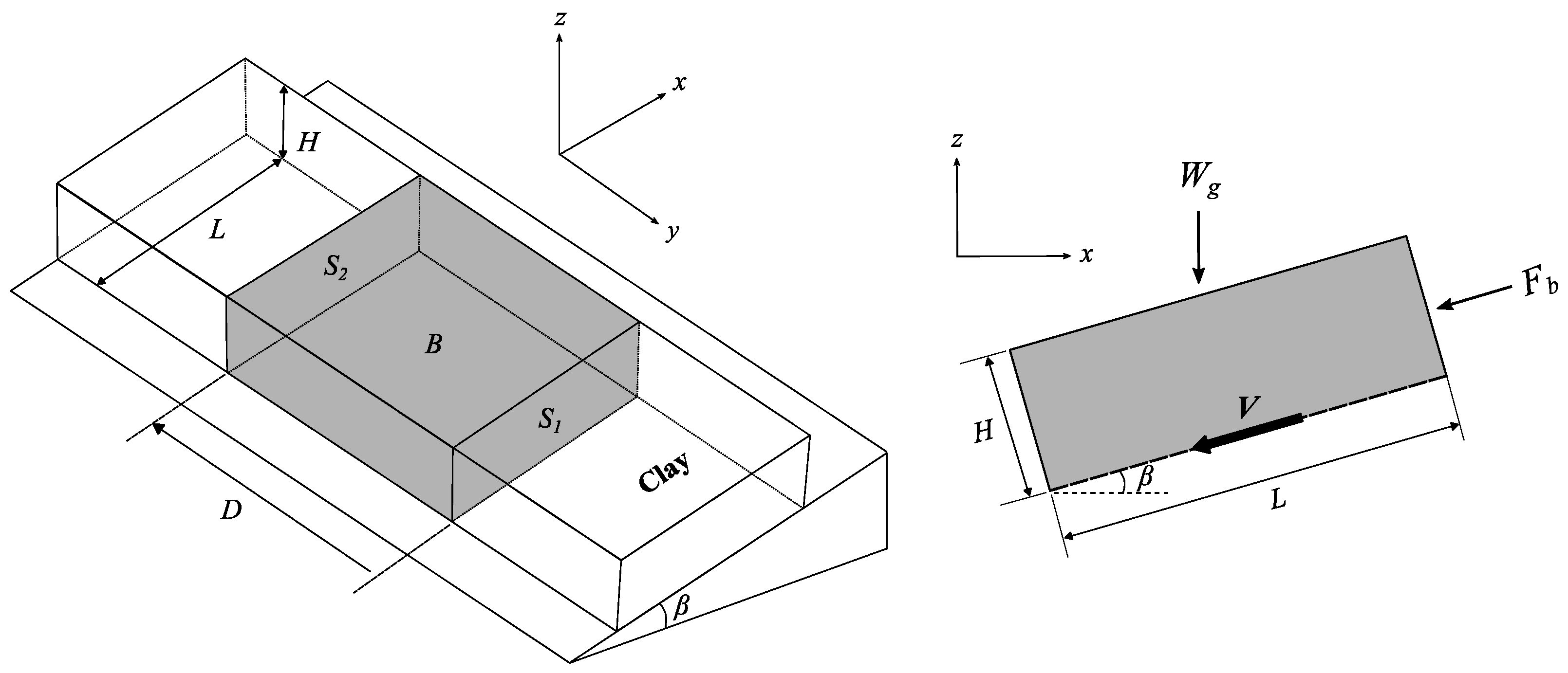
2.1. Assumption

Following Chen [29], in this study, the present upper bound solution assumes the following: (1) the undrained condition with fully saturated clay ground; (2) the kinematically admissible failure mechanism (or velocity field); (3) the occurrence of plastic dissipation limited to the failure surfaces derived from the admissible velocity field; (4) full dissipation of the external power to generate the plastic slip along the failure surface. Based on these assumptions, the present study considered three failure modes: block; triangular wedge; and trapezoidal wedge failure modes. In each failure mode, the soil block moves along the failure surfaces, and plastic dissipation is generated along the bottom and side failure planes. For a saturated clay under undrained conditions coupled with the Tresca plasticity model (the Mohr–Coulomb plasticity model with zero friction angle), the plastic dissipation rate along the failure surface D is given by Woo and Beak [25]:
D = c u V A
where cu is the undrained shear strength of the clay; V is the velocity along the failure surface, and A is the area of the failure surface. In the calculation of total external power, this study considered the vehicle weight and soil thrust as vertical and horizontal external forces, respectively. The weight of the soil block was ignored as the magnitude was very small compared to the vehicle weight. Based on these assumptions, the following sections derive the upper bound solutions for the soil thrust for each failure mode.

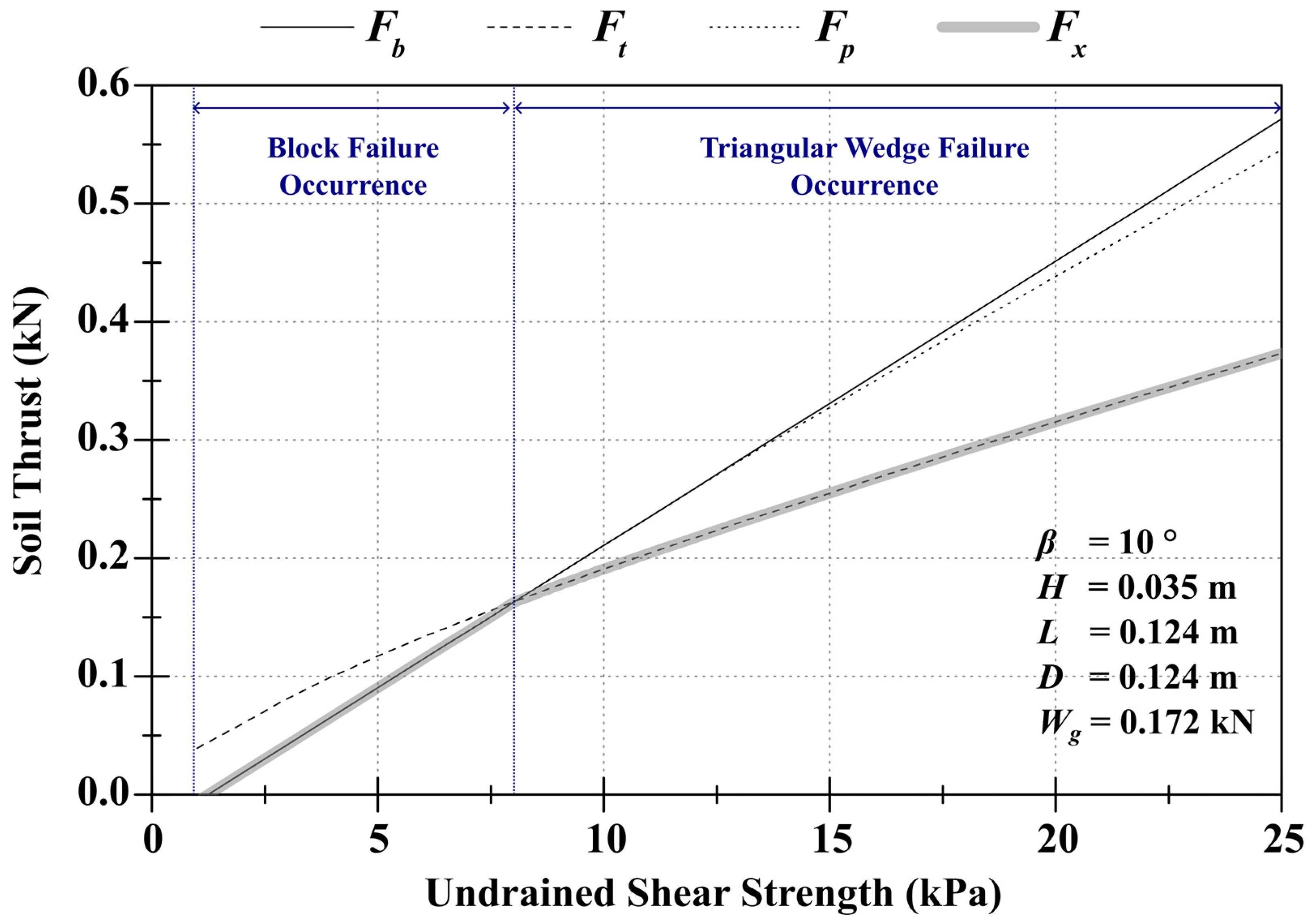
2.2. Block Failure Mode

Figure 1 schematically illustrates the block failure mechanism when a vehicle ascends a slope with angle β. In Figure 1, surface B represents the bottom failure plane, while surfaces S1 and S2 are the lateral failure planes. The dimensions H, L, and D denote the height, length, and width of a single-track system, respectively. The force Wg, aligned with the gravitational force, represents the weight transmitted from the upper vehicle. The force Fb, parallel to the slope, indicates the soil thrust. In the block failure mode, the brick-shaped soil block moves at velocity V.
In these conditions, the total external power P is given by
P = F b + W g sin β V ,
which corresponds to the sum of inner products between external forces (Wg and Fb) and velocity V. As there exist one bottom and two side failure planes, the total dissipation rate D is expressed as
D = D s + D b ,
where Db and Ds represent plastic dissipation rates along the bottom failure surface B and side failure surfaces (S1 and S2), respectively. Along surface B, plastic dissipation rate Db is written as
D b = c u L D V .
Along two side failure surfaces, plastic dissipation rate Ds is
D s = 2 c u L H V .
Thus, the total dissipation rate D is expressed as
D = D b + D s = c u L D V + 2 c u L H V = c u L V D + 2 H .
By assuming that all energy is dissipated to generate plastic deformation, the total external power P is identical to the total (internal) plastic dissipation rate D; thus, equating P = D gives the soil thrust Fb as
F b = c u L D + 2 H W g sin β ,
which shows that the soil thrust from the block failure mode is deterministic.

2.3. Triangular Wedge Failure Mode

Figure 2 schematically describes the failure mechanism of the triangular wedge failure mode. In Figure 2, surface B is an inclined bottom failure plane forming an angle θ with the ground surface, while surfaces S1 and S2 are two triangular side failure planes. In the triangular wedge failure mode, the prism-shaped soil block moves at velocity V.
In this case, total external power P is expressed as
P = F t + W g sin β V sin θ W g V cos β cos θ ,
where Ft represents the soil thrust under the triangular wedge failure mode. For the triangular wedge failure mode, plastic dissipation rate Db along the bottom failure surface B is defined in
D b = c u H cos θ D V ,
whereas, along the two triangular-shaped side failure surfaces S1 and S2, plastic dissipation rate Ds is expressed as
D s = 2 c u H 2 tan θ 2 V = c u tan θ H 2 V .
Consequently, the total dissipation rate D is formulated as
D = D b + D s = c u H cos θ D V + c u tan θ H 2 V = c u H D cos θ + tan θ H V .
Assuming that total external power is entirely dissipated to produce the plastic deformation along failure surfaces, the soil thrust Ft can be written as
F t = c u H D sin θ cos θ + H cos θ + W g cos β cos θ sin θ sin β ,
which shows that the soil thrust Ft is a function of the geometric variable θ. Therefore, the stationary upper bound solution is identified at the angle θ where ∂Ft/∂θ = 0; thus,
F t θ = c u H D cos 2 θ D sin 2 θ + H sin θ cos 2 θ + W g cos β cos 2 θ sin 2 θ cos β ,
which can be reorganized by
sin 3 θ + W g cos β c u H 2 + 2 D H sin 2 θ W g cos β c u H 2 + D H = 0 ,
which is a third-order polynomial equation of sinθ. Although there is an analytical way to solve Equation (14) for θ, the present research numerically solves it using the bisection method, which is very efficient when the solution range is definite (in this problem, 0 < θ < tan−1(L/H)).

2.4. Trapezoidal Wedge Failure Mode

Figure 3 schematically illustrates the failure mechanism in the trapezoidal wedge failure mode. In this mode, a trapezoid-shaped soil block forming an angle θ with the ground surface moves at velocity V.
Under the trapezoidal wedge failure mode, the total P power is expressed as
P = F p + W g sin β V sin θ W g V cos β cos θ .
The dissipation rates Db (along the slip surface B) and Ds (along the two side failure surfaces S1 and S2) are given as
D b = c u L sin θ D V ,
D s = 2 c u L H L 2 2 tan θ V = c u L 2 H L tan θ V .
The total dissipation rate D is then
D = D b + D s = c u L sin θ D V + c u L 2 H L tan θ V = c u L D sin θ + 2 H L tan θ V .
Assuming that the total work is fully dissipated, the following equation is derived.
F p + W g sin β V sin θ W g V cos β cos θ = c u L D sin θ + 2 H L tan θ V .
Thus, the soil thrust Fp is
F p = c u L D L cos θ sin 2 θ + 2 H sin θ + W g cos β cos θ sin θ sin β .
Given that cu, H, L, D, and Wg are known in Equation (20), the least upper solution obtained by setting the gradient of Fp with respect to θ should be zero:
F p θ = c u L L sin θ 2 H cos θ sin 2 θ 2 D L cos θ cos θ sin 3 θ                                 + W g cos β cos 2 θ sin 2 θ cos β = 0 ,
which yields
sin 2 θ + 2 L H sin θ + D 1 sin 2 θ W g cos β c u L 2 sin θ 2 = 0 .
Equation (22) represents a nonlinear equation of sinθ. This study employed the bisection method to solve it, with θ ranging from tan−1(L/H) to 90°. Once θ is determined, the soil thrust Fp can be calculated using Equation (20).

2.5. Upper Bound Solution

The upper bound theorem states that the collapse loads derived from any admissible velocity field are always higher than the actual collapse load [29]; therefore, the lowest load among those calculated from the various admissible velocity fields serves as a reasonable approximation of the actual collapse load. In this study, the soil thrust Fx is determined as the minimum value among Fb from the block failure mode, Ft from the triangular wedge failure mode, and Fp from the trapezoidal failure mode, as shown in Equation (23) and Figure 4.
F x = min F b ,   F t ,   F p .

3. Verification with Numerical Solutions

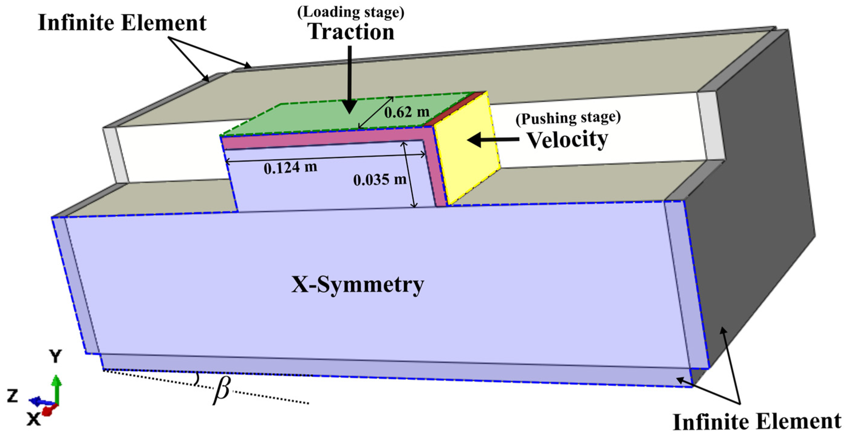
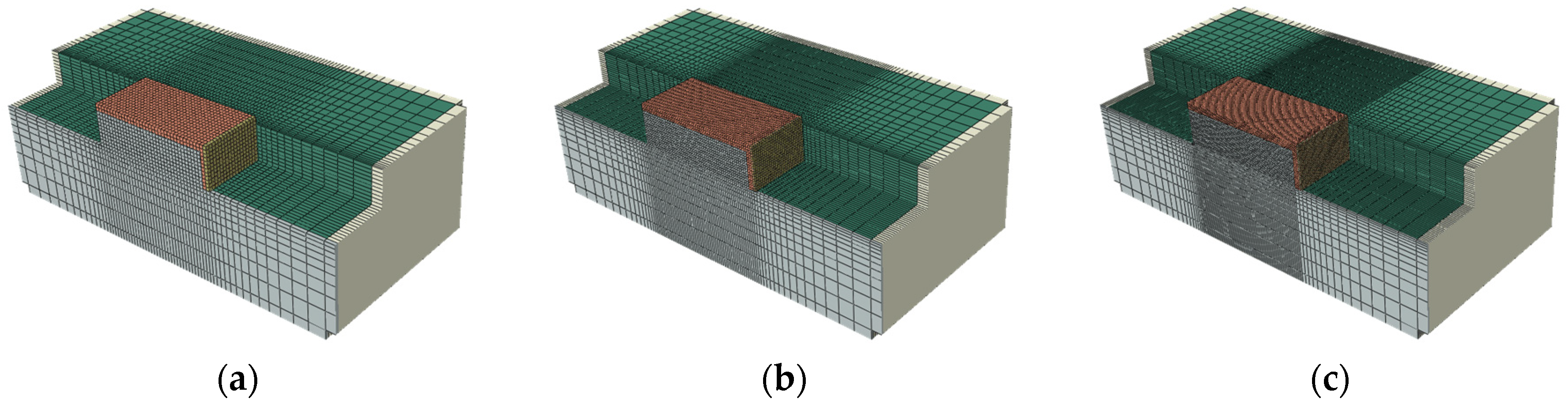
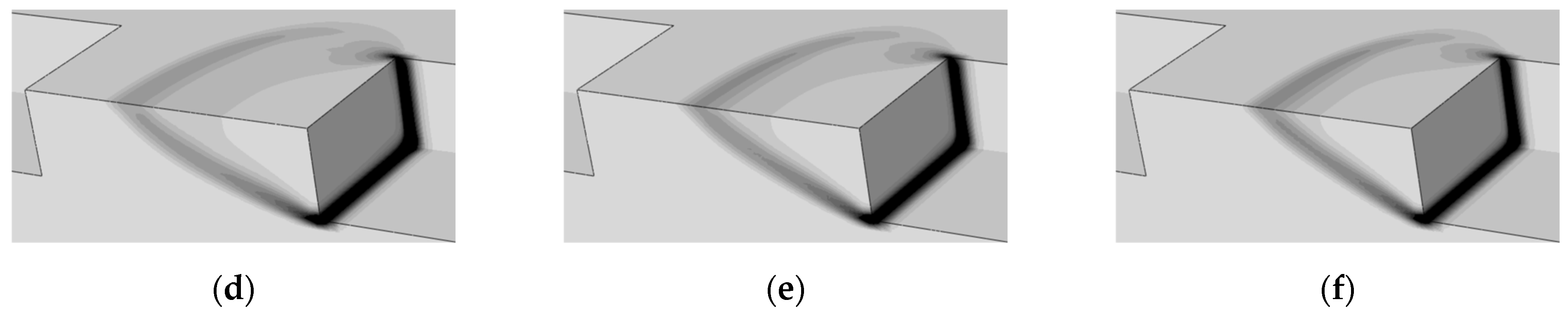
3.1. Numericla Modeling

Woo and Beak [25] verified the analytical solution of soil thrust through numerical analysis and model experiments on a flat ground surface in their study; following this, this study performed numerical analyses to validate the proposed theoretical solution for a track system on a clay slope. The interaction between the track and the ground was simulated using ABAQUS Explicit. Table 1 lists the material properties of both the ground and the track system considered in the numerical analyses. The track system was modeled as a linear elastic material employing the material properties of steel. In the numerical analysis, this study described the mechanical responses of the saturated clay using a linear elastic–perfect plastic constitutive model coupled with the Tresca yield criterion (Mohr–Coulomb yield criterion with zero friction angle). The elastic behavior was modeled as a linear elastic model with Young’s modulus E = 20,000 kPa and Poisson’s ratio ν = 0.49 (to describe the undrained responses), while its plastic behavior was described using the Tresca model with its yield strength corresponding to the undrained shear strength of clay assuming the perfect plastic condition. To examine the influence of the undrained shear strength cu of clay, this study conducted the numerical analyses by varying its values to 5, 7.5, 10, 15, 20, and 25 kPa.
Figure 5 depicts the geometric modeling of a track system and subgrade clay ground in the numerical analyses of this study. To improve the efficiency of the numerical analysis, a half section of the entire domain considering x-symmetricity was modeled, as shown in Figure 5. In Figure 5, the ground slope angle β was set at 10°; regarding the track system, its height, length, and width were set to 0.035, 0.124, and 0.062 m, respectively. To speed up the numerical analyses, a mass scaling factor of 400 was applied to all simulations. The outer boundaries of the ground (except the symmetric boundary) were modeled using infinite elements to minimize the disturbance caused by reflection.
The numerical analysis consists of two stages: loading; and pushing. In the loading stage, the surface traction (σc = 11.2 kPa = Wg/(LD)) was uniformly applied as traction on the upper surface of the track. The perpendicular and tangential components of traction with respect to the surface were σc sinβ and σc cosβ, respectively. The interface between the track and clay was modeled as the frictionless contact model. In the pushing stage, the front panel of the track was pushed at 1 mm/s velocity parallel to the ground surface (that had an angle β with the horizontal surface); this stage was maintained for 7.5 s, and the final displacement of the track was 7.5 mm.
To verify the convergence of the numerical simulations, this study carried out multiple simulations under consistent conditions while adjusting the mesh density. Figure 6 illustrates three different mesh configurations considered in this study. The section around the track system has the smallest and most uniform mesh; the mesh spacing increases gradually toward the outer boundaries. In Figure 6a, which has the lowest mesh density, the smallest node spacing is 3.6 mm; the total numbers of nodes and elements are 43,865 and 39,530, respectively. In Figure 6b, the intermediate mesh density case, the smallest node spacing is 2.4 mm; the total numbers of nodes and elements are 96,131 and 88,684, respectively. In Figure 6c, the highest mesh density case, the smallest node spacing is 1.8 mm; the total numbers of nodes and elements are 162,893 and 152,324, respectively.

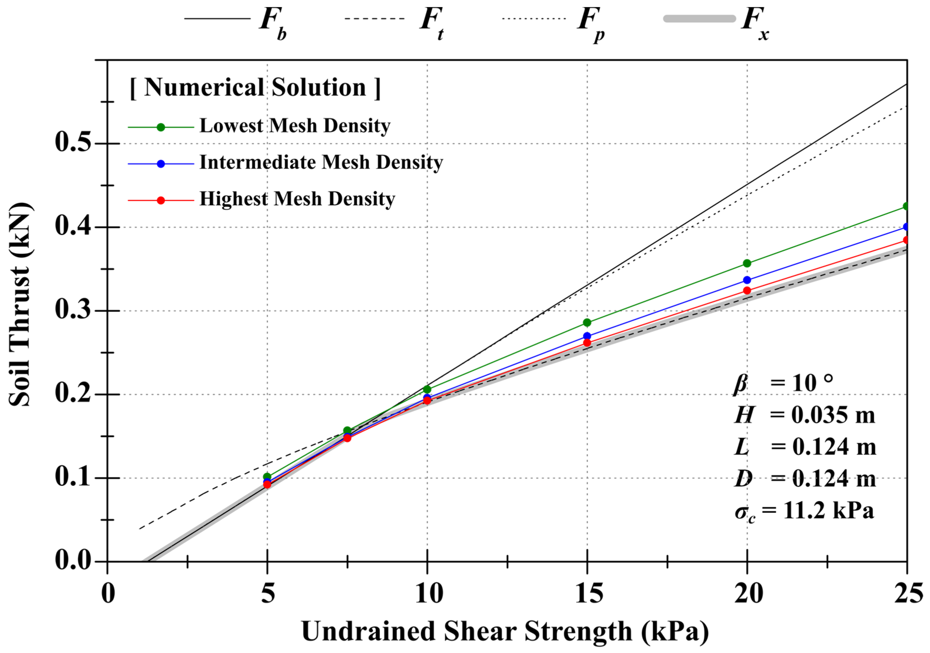
3.2. Comparison of Upper Bound Solutions with Numerical Analysis Result
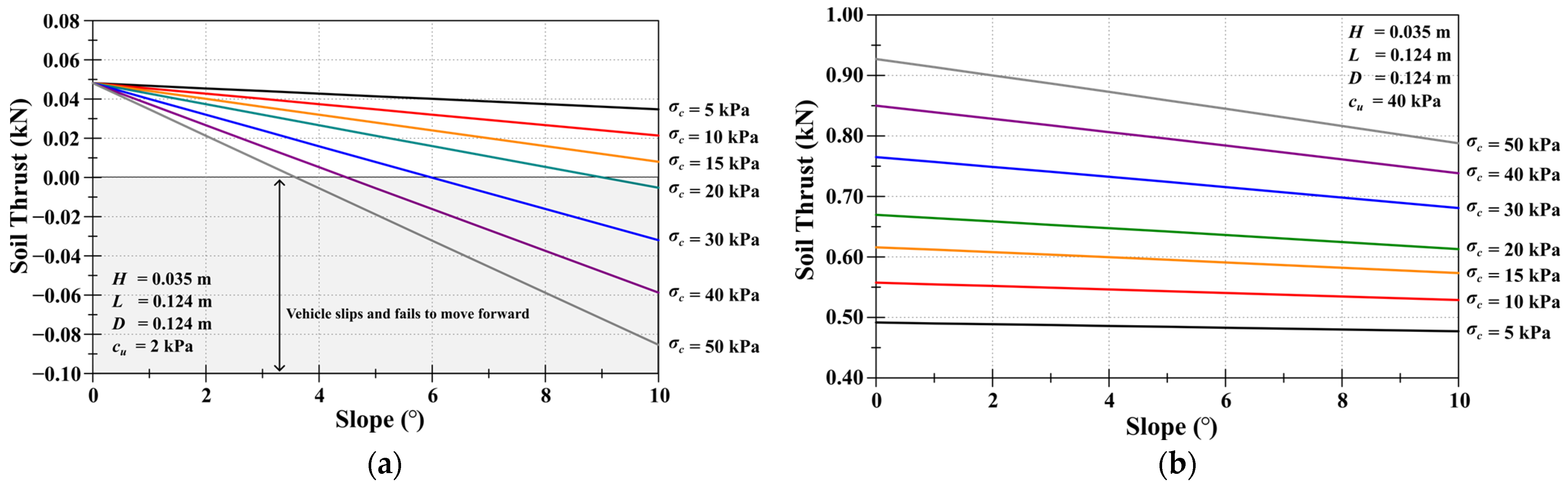
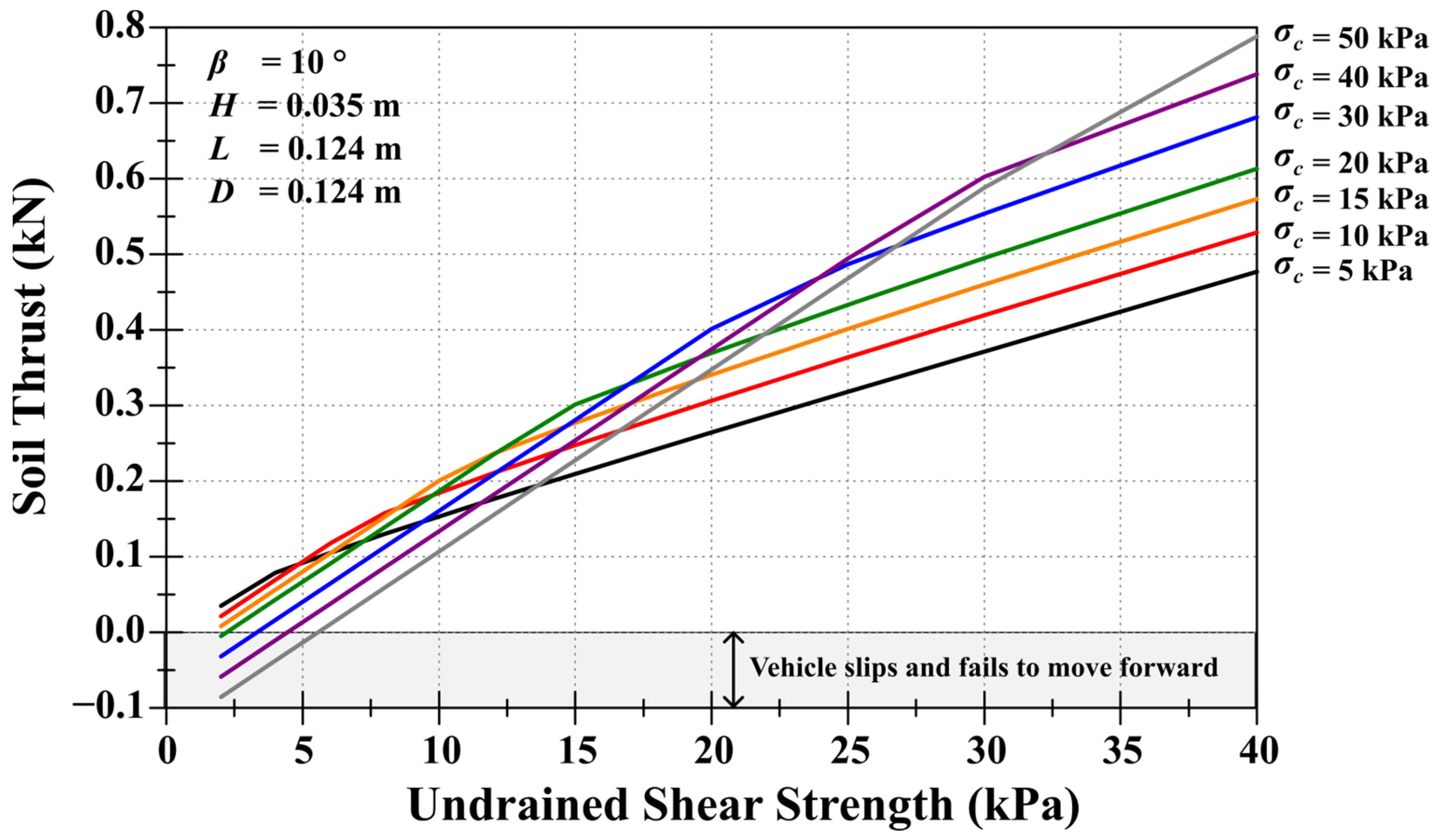
Figure 7 shows the soil thrust (both upper bound and numerical solutions) with respect to cu with the identical σc, β, and dimensions H, L, and D, as cited by Beak et al. [22]. In the numerical analysis results, the soil thrust is calculated by doubling the sum of the reaction force at all nodes on the front panel of the track, where velocity was constrained. Once the soil thrust converged in the numerical analyses, the final soil thrust was estimated by averaging soil thrust values for 1.5 s.
In Figure 7, solid, dashed, and dotted lines represent Fb (from the block failure mode), Ft (from the triangle wedge failure mode), and Fp (from the trapezoidal failure mode), while the thick gray solid line represents the upper bound solution Fx, which is the minimum between Fb, Ft, and Fp. In Figure 7, when cu is less than about 8 kPa, Fb is less than Ft and Fp; thus, in this case, Fx = Fb. If cu is greater than 8 kPa, Ft is smaller than Fb and Fp; thus, in this case, Fx = Ft. Figure 7 also plots the numerical solutions overlapped with the upper bound solutions. In Figure 7, the green, blue, and red symbols correspond to the numerical solutions with the lowest, intermediate, and highest mesh densities. As mesh density increases, the numerical solution more closely approximates the analytical solution proposed in this study; the general rule in the numerical simulation is that the numerical analysis with the finer mesh approaches the exact solution; thus, the analytical solution in this study is very close to the exact solution.
Figure 8 shows the distribution of equivalent plastic strain in the ground from the results of the numerical simulation with the highest mesh density. When cu = 4 kPa (Figure 8a), the numerical solution clearly shows the block failure, which is identical to the failure mode determined by the upper bound solution. When cu =15, 20, and 25 kPa (Figure 8d–f), the numerical solutions definitely depict the triangular wedge failure mode, which is identical to the failure mode determined by the upper bound solution; in Figure 8d–f, as cu increases, the length of the triangular wedge decreases. When cu is 7.5 and 10 kPa, as shown in Figure 8b,c, as the failure mode transitions from the block to the triangular wedge modes, numerical analyses simulated both failure modes concurrently. This implies that, as cu increases, rather than an abrupt change in the failure mode, both failure modes occur simultaneously. As a result, following the comparison with the numerical solution, the proposed upper bound solution can accurately predict the soil thrust value and the corresponding failure mode.

4. Parametric Study

This study analyzed the influence of parameters (geometry, vehicle design, and ground strength) on the soil thrust over clay slope using the proposed upper bound theoretical solution. Table 2 lists the parameters considered; this study considered the ground slope as a geometry parameter and undrained shear strength cu as a ground strength parameter. For the vehicle parameters, this study included ground contact pressure σc, track height H, track length L, and track width D. Table 2 also presents the values and ranges of the considered parameters.
According to Costello et al. [30], 95.5% of the seabed has slopes of 6° or less, while only 4.5% exceed this angle; consequently, the slope angle (β) was set within a range of 0° (which represented the flat surface) to 10° (which corresponded to the extreme slope). For the ground contact pressure (σc), this study established a range of 5 to 50 kPa to cover the diverse types of underwater heavy vehicles. For the undrained shear strength cu, following Spagnoli, Freudenthal, Spagnoli et al. [27], this study set a range of cu from 2 to 40 kPa. Following Baek et al. [22], the height, length, and width of a track system were set to 0.035, 0.124, and 0.124 m, respectively. Additionally, to assess the impact of these aspect ratios, the upper bound solution was calculated and compared while varying the dimensions of height, length, and width.
This study parametrically studied the responses of the stationary upper bound solution Fx (=min(Fb, Ft, Fp)) with respect to the considered parameters (β, cu, σc, H, L, and D).
Figure 9 illustrates how soil thrust responds to the changes in β and σc, while cu and H, L, and D remain constant (dimensions cited from Beak et al. [22]). Figure 9a plots the soil thrust versus the angle β, where the block failure predominates due to low undrained shear strength (cu = 2 kPa), while Figure 9b illustrates the soil thrust against the angle β, where the triangle wedge failure predominates because of high undrained shear strength (cu = 40 kPa). As the angle β increases for all failure modes, there is a noticeable decrease in soil thrust; this decrease is further amplified as σc increases. In very soft ground conditions (Figure 9a), soil thrust becomes negative with higher β and σc, indicating that the tracked vehicle cannot climb the slope and begins to slip downward. On the other hand, in stiff ground conditions (Figure 9b), where the triangular wedge failure is dominant, the soil thrust remains positive, enabling the vehicle to climb the slope.
Figure 10 displays how soil thrust changes with cu and σc while β is constant, and dimensions H, L, D from Beak et al. [22] are also fixed. As σc increases, the kink point, where the failure mode transitions from the block failure mode to triangle wedge failure mode, moves to the upper left side. This implies that the tendency of the block failure mode increases with the vehicle load. In Figure 10 (and Figure 9a), when σc increases with low cu, negative soil thrust occurs, causing the vehicle to slip down. Before the kink points (where block failure mode happens), with fixed cu, higher soil thrust is generated as σc is lower (cu = 2 kPa in Figure 10); however, after the kink points (where triangular wedge failure mode happens), with fixed cu, the higher soil thrust is generated as σc is higher (cu = 35 kPa in Figure 10).
Subsequently, this study examined the effect of dimensions (H, L, and D) of the track system on vehicle slippage on a clay slope. As shown in Figure 9, the most critical case is that the heavy vehicle climbs up a slope consisting of very soft clay, where the block failure mode is dominant; thus, the present analysis only considered the block failure mode with fixed slope (β = 8°) and σc (=40 kPa) and with varied undrained shear strength cu and dimensions (H, L, and D) of the track.
Figure 11 illustrates soil thrust versus cu with the different dimensions of the track system. The dashed line represents soil thrust for the default dimensions (H = 0.035 m, L = 0.124 m, and D = 0.124 m, cited from Beak et al. [22]), while the solid colored lines indicate soil thrust against cu for modified dimensions ((3H, L, D), (H, 3L, D), and (H, L, 3D)). As illustrated in Figure 11, increasing H (solid blue line) leads to a rise in both the intercept and slope of the soil thrust curve with respect to cu; however, increasing L or D (solid green or orange line) increases the slope of the soil thrust curve while reducing its intercept, which does not cut negative soil thrust region along the horizontal axis (or cu axis). With the definition of σc (=Wg/(LD)), Equation (7) can be rewritten as
F b = c u L D + 2 H σ c L D sin β .
In Equation (24), an increase in H causes the first term cuL(D + 2H) to increase, while the second term σcLDsinβ remains unchanged; accordingly, the soil thrust Fb increases. As L and D increase, however, the first and second terms increase together, and the second term σcLDsinβ is also proportional to σc. Since soil thrust is calculated by subtracting these terms, increases in L and D do not significantly boost soil thrust; in fact, they sometimes result in a reduction as the second term σcLDsinβ increases. Therefore, when operating underwater heavy tracked vehicles on very soft ground where negative soil thrust is a concern, it is necessary to select a more effective strategy adjusted to site conditions: an increase in the track height or a reduction in the vehicle weight.

5. Conclusions

This study proposes a three-dimensional upper bound solution for estimating soil thrust on a clay slope for tracked vehicles. It assumes that the failure modes of clayey soil include block, triangular wedge, and trapezoidal wedge failures. An upper bound solution for each mode was formulated and provided. Using the principle of the least action, the minimum upper bound solution was selected as the analytical soil thrust. This analytical solution was validated through numerical analyses that simulated track-ground interactions.
The parametric analysis of the analytical solution on clay slope shows that only block and triangular wedge failures occur, with trapezoidal wedge failure absent. As the ground slope angle increases, there is a corresponding decrease in soil thrust. For a constant slope angle, the reduction in soil thrust became more noticeable as the vehicle weight increased; in extreme cases, this can result in negative soil thrust, causing the vehicle to slip and be unable to move forward.
Although further validation through model and field experiments with consideration of various clay ground and tracked vehicles is desirable to confirm the applicability of the proposed solution, the analytical solution and parametric analysis results presented in this study offer a rapid way to assess vehicle operability on a clay slope in real time.

Author Contributions

Conceptualization, S.S. and S.I.W.; methodology, S.S. and S.I.W.; formal analysis, S.S.; writing—original draft preparation, S.S. and S.I.W.; writing—review and editing, S.S. and S.I.W.; visualization, S.S. and S.I.W.; supervision, S.I.W. All authors have read and agreed to the published version of the manuscript.

Funding

This work was supported by the Incheon National University Research Grant in 2023.

Institutional Review Board Statement

Not applicable.

Informed Consent Statement

Not applicable.

Data Availability Statement

The data presented in this study are available upon reasonable request from the corresponding author.

Acknowledgments

The corresponding author gratefully acknowledges the financial support of the Incheon National University Research Grant 2023.

Conflicts of Interest

The authors declare no conflicts of interest.

References

  1. Guo, X.; Fan, N.; Liu, Y.; Liu, X.; Wang, Z.; Xie, X.; Jia, Y. Deep seabed mining: Frontiers in engineering geology and environment. Int. J. Coal Sci. Technol. 2023, 10, 23. [Google Scholar] [CrossRef]
  2. Kang, Y.; Liu, S. The Development History and Latest Progress of Deep-Sea Polymetallic Nodule Mining Technology. Minerals 2021, 11, 1132. [Google Scholar] [CrossRef]
  3. Hu, Q.; Li, Z.; Zhai, X.; Zheng, H. Development of Hydraulic Lifting System of Deep-Sea Mineral Resources. Minerals 2022, 12, 1319. [Google Scholar] [CrossRef]
  4. Cho, S.-g.; Park, S.; Oh, J.; Min, C.; Kim, H.; Hong, S.; Jang, J.; Lee, T.H. Design optimization of deep-seabed pilot miner system with coupled relations between constraints. J. Terramech. 2019, 83, 25–34. [Google Scholar] [CrossRef]
  5. Leng, D.; Shao, S.; Xie, Y.; Wang, H.; Liu, G. A brief review of recent progress on deep sea mining vehicle. Ocean Eng. 2021, 228, 108565. [Google Scholar] [CrossRef]
  6. Chen, Q.; Yang, J.; Mao, J.; Liang, Z.; Lu, C.; Sun, P. A path following controller for deep-sea mining vehicles considering slip control and random resistance based on improved deep deterministic policy gradient. Ocean Eng. 2023, 278, 114069. [Google Scholar] [CrossRef]
  7. Vu, M.T.; Choi, H.-S.; Kim, J.-Y.; Tran, N.H. A study on an underwater tracked vehicle with a ladder trencher. Ocean Eng. 2016, 127, 90–102. [Google Scholar] [CrossRef]
  8. Wong, J.Y. Terramechanics and Off-Road Vehicle Engineering: Terrain Behaviour, Off-Road Vehicle Performance and Design; Butterworth-Heinemann: Oxford, UK, 2009. [Google Scholar]
  9. Bekker, M.G. Theory of Land Locomotion; University of Michigan Press: Ann Arbor, MI, USA, 1956. [Google Scholar]
  10. Grečenko, A. Re-examined principles of thrust generation by a track on soft ground. J. Terramech. 2007, 44, 123–131. [Google Scholar] [CrossRef]
  11. Grečenko, A. Compression–Sliding approach: Dependence of transitional displacement of a driving element on its size and load. J. Terramech. 2011, 48, 325–332. [Google Scholar] [CrossRef]
  12. Baek, S.-H.; Shin, G.-B.; Chung, C.-K. Assessment of the side thrust for off-road tracked vehicles based on the punching shear theory. J. Terramech. 2018, 79, 59–68. [Google Scholar] [CrossRef]
  13. Shin, G.-B.; Baek, S.-H.; Park, K.-H.; Chung, C.-K. Investigation of the soil thrust interference effect for tracked unmanned ground vehicles (UGVs) using model track tests. J. Terramech. 2020, 91, 117–127. [Google Scholar] [CrossRef]
  14. Yang, C.; Cai, L.; Liu, Z.; Tian, Y.; Zhang, C. A calculation method of track shoe thrust on soft ground for splayed grouser. J. Terramech. 2016, 65, 38–48. [Google Scholar] [CrossRef]
  15. Li, J.; Sun, S.; Sun, C.; Liu, C.; Tang, W.; Wang, H. Analysis of Effect of Grouser Height on Tractive Performance of Tracked Vehicle under Different Moisture Contents in Paddy Soil. Agriculture 2022, 12, 1581. [Google Scholar] [CrossRef]
  16. Wang, M.; Wang, X.; Sun, Y.; Gu, Z. Tractive performance evaluation of seafloor tracked trencher based on laboratory mechanical measurements. Int. J. Nav. Archit. Ocean Eng. 2016, 8, 177–187. [Google Scholar] [CrossRef]
  17. Li, J.; Liu, S.; Dai, Y. Effect of grouser height on tractive performance of tracked mining vehicle. J. Braz. Soc. Mech. Sci. Eng. 2017, 39, 2459–2466. [Google Scholar] [CrossRef]
  18. Li, Y.; He, D.; Si, Q.; Meng, X. Effect of track shoes structural parameters on traction performance of unmanned underwater tracked bulldozer. Ocean Eng. 2021, 237, 109655. [Google Scholar] [CrossRef]
  19. Sun, P.; Lu, H.; Yang, J.; Liu, M.; Li, S.; Zhang, B. Numerical study on shear interaction between the track plate of deep-sea mining vehicle and the seafloor sediment based on CEL method. Ocean Eng. 2022, 266, 112785. [Google Scholar] [CrossRef]
  20. Xu, Z.; Liu, Y.; Yang, G.; Xia, J.; Dou, Z.; Meng, Q.; Xu, X. Research on contact model of track-soft sediment and traction performance of four-tracked seabed mining vehicle. Ocean Eng. 2022, 259, 111902. [Google Scholar] [CrossRef]
  21. Xu, F.; Sun, Y.; Zhang, Y.; Li, Z.; Zhang, L. Discovery and verification of traction weakening effect between multi track shoe of deep-sea miner and sediment. Ocean Eng. 2023, 283, 115045. [Google Scholar] [CrossRef]
  22. Baek, S.-H.; Shin, G.-B.; Chung, C.-K. Experimental study on the soil thrust of underwater tracked vehicles moving on the clay seafloor. Appl. Ocean Res. 2019, 86, 117–127. [Google Scholar] [CrossRef]
  23. Wang, L.; Chen, X.; Wang, L.; Li, Z.; Yang, W. Mechanical properties and soil failure process of interface between grouser of tracked mining vehicle and deep-sea sediment. Ocean Eng. 2023, 285, 115336. [Google Scholar] [CrossRef]
  24. Woo, S.I.; Baek, S.-H. Upper-Bound Analysis for Soil Thrust of Single-Track System over Clay Ground. Int. J. Geomech. 2020, 20, 06019023. [Google Scholar] [CrossRef]
  25. Woo, S.I.; Beak, S.-H. Upper-bound solutions for the soil thrust of clay under a track system in 3D conditions. J. Terramech. 2023, 105, 41–51. [Google Scholar] [CrossRef]
  26. Na, S.H.; Woo, S.I. Theoretical Evaluation for Soil Thrust of Single-Track System over Clay Slope via Upper Bound Analysis. Appl. Sci. 2023, 13, 5222. [Google Scholar] [CrossRef]
  27. Spagnoli, G.; Freudenthal, T.; Strasser, M.; Weixler, L. Development and possible applications of Mebo200 for geotechnical investigations for the underwater mining. In Proceedings of the Offshore Technology Conference, Houston, TX, USA, 5–8 May 2014. [Google Scholar]
  28. Grečenko, A. Thrust and slip of a track determined by the compression–sliding approach. J. Terramech. 2007, 44, 451–459. [Google Scholar] [CrossRef]
  29. Chen, W.-F. Limit Analysis in Soil Mechanics; Elsevier: Amsterdam, The Netherlands, 1990. [Google Scholar]
  30. Costello, M.J.; Cheung, A.; De Hauwere, N. Surface area and the seabed area, volume, depth, slope, and topographic variation for the world’s seas, oceans, and countries. Environ. Sci. Technol. 2010, 44, 8821–8828. [Google Scholar] [CrossRef]
Figure 1. Schematic diagram of the block failure mode for a single-track system.
Applsci 14 04335 g001
Figure 2. Schematic diagram of the triangular wedge failure mode for a single-track system.
Applsci 14 04335 g002
Figure 3. Schematic diagram of the trapezoidal wedge failure mode for a single-track system.
Applsci 14 04335 g003
Figure 4. Soil thrust Fx versus the undrained shear strength cu of clay with fixed dimensions of a track system (height H, length L, and width D), as referred to in Beak et al. [22]; ground slope β and weight Wg transmitted from the upper vehicle.
Applsci 14 04335 g004
Figure 5. Geometrical modeling of a track system over clay slope for the numerical simulations in this study.
Applsci 14 04335 g005
Figure 6. Mesh configurations applied to the numerical analysis: (a) lowest mesh density; (b) intermediate mesh density; and (c) highest mesh density.
Applsci 14 04335 g006
Figure 7. Upper bound solutions (Fb, Ft, Fp) and minimum upper bound solution Fx overlapped with numerical solutions with different mesh densities.
Applsci 14 04335 g007
Figure 8. Equivalent plastic strain distribution when undrained shear strength cu is (a) 5 kPa, (b) 7.5 kPa, (c) 10 kPa, (d) 15 kPa, (e) 20 kPa, and (f) 25 kPa.
Applsci 14 04335 g008aApplsci 14 04335 g008b
Figure 9. Soil thrust versus ground slope angle with varying ground contact pressure σc with (a) very soft clay ground (cu = 2 kPa) and (b) stiff clay ground (cu = 40 kPa).
Applsci 14 04335 g009
Figure 10. Soil thrust versus undrained shear strength cu with different ground contact pressure σc.
Applsci 14 04335 g010
Figure 11. Examination of the influence of dimensions of a track system.
Applsci 14 04335 g011
Table 1. Material parameters in the numerical analyses in this study.
MaterialClay GroundTrack System
Density ρ (t/m3)2.07.8
Young’s modulus E (kPa)20,000210 × 10⁶
Poisson’s ratio ν0.490.3
Plasticity modelTresca-
Cohesion cu (kPa)5, 7.5, 10, 15, 20, 25-
Table 2. Parameters and their ranges in the parametric study.
ParametersValues
GeometrySlope angleβ (°)0~10
Ground StrengthUndrained shear strengthcu (kPa)2~40
VehicleGround contact pressureσc (kPa)5~50
Height of the trackH (m)0.035, 0.105
Length of the trackL (m)0.124, 0.372
Width of the trackD (m)0.124, 0.372
Disclaimer/Publisher’s Note: The statements, opinions and data contained in all publications are solely those of the individual author(s) and contributor(s) and not of MDPI and/or the editor(s). MDPI and/or the editor(s) disclaim responsibility for any injury to people or property resulting from any ideas, methods, instructions or products referred to in the content.

