
Vibration Isolation and Launch Performance Enhancement of the Spacecraft In-Orbit Launch Design Using the Nonlinear Dynamic Feature


Abstract
1. Introduction
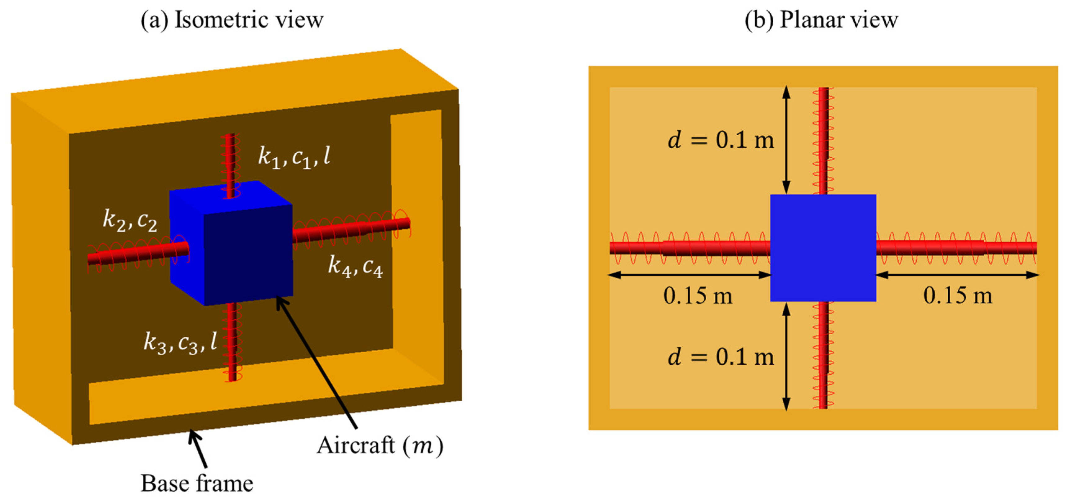
2. Design Concept
3. Mathematical Modeling
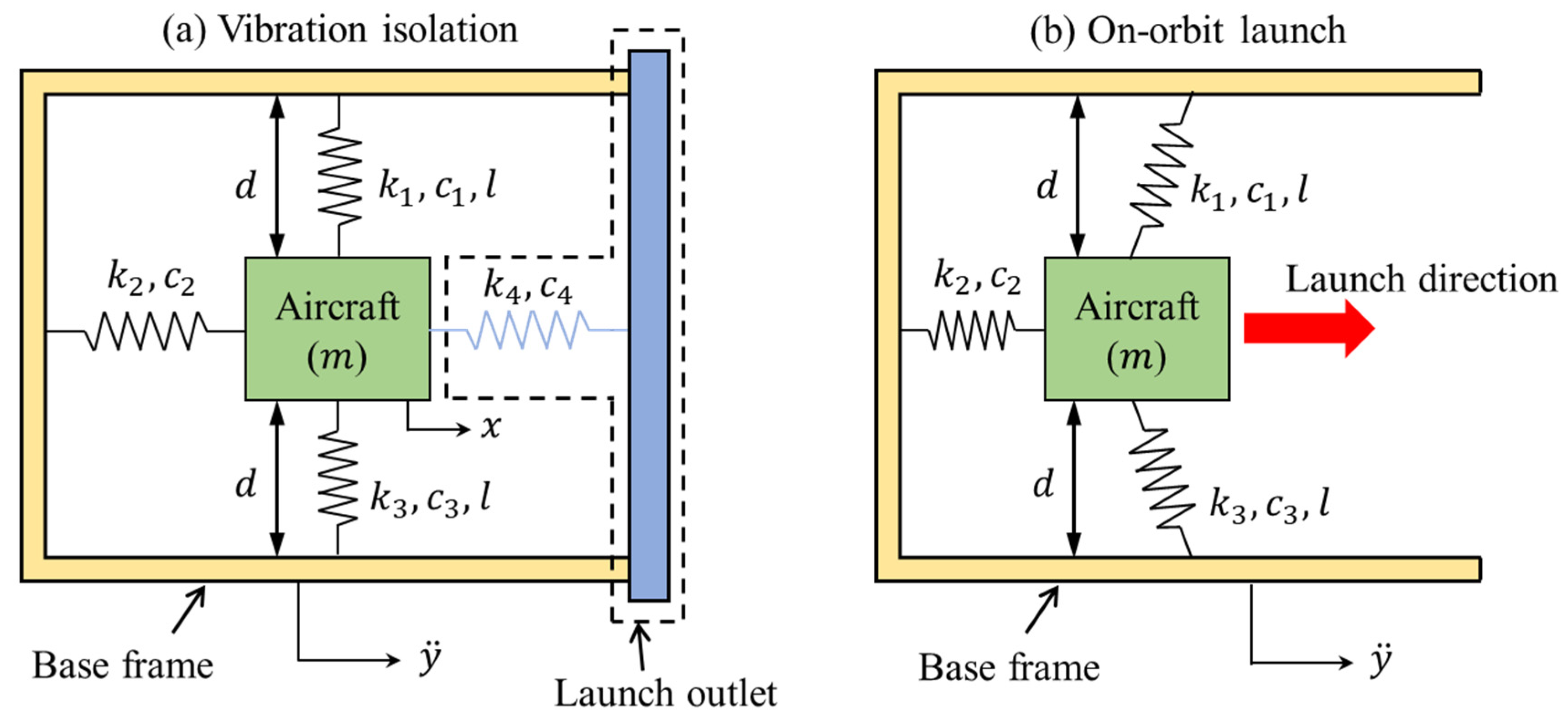
3.1. Dynamic Equations When the Launch Is Off
3.2. Dynamic Equations When the Launch Is On
4. Performance Comparison
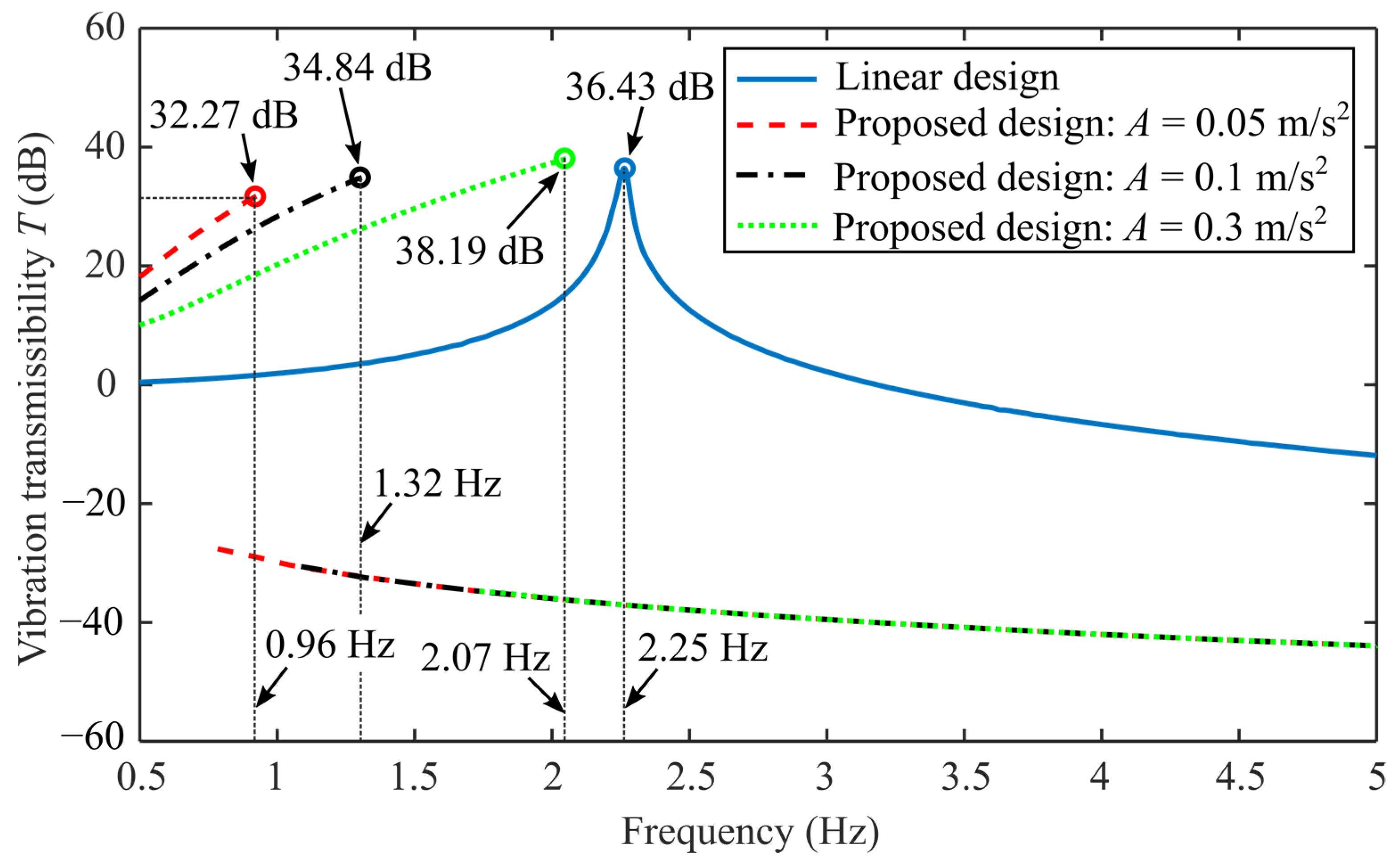
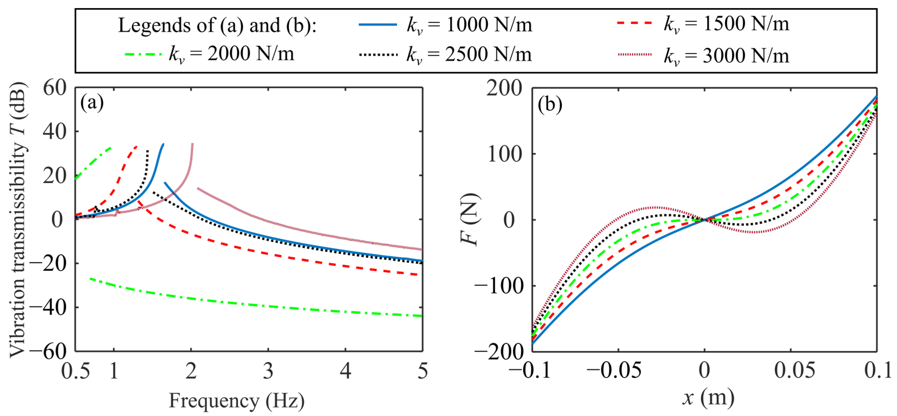
4.1. Vibration Isolation Performance Comparison
4.2. Launch Velocity Comparison
5. Parametric Study
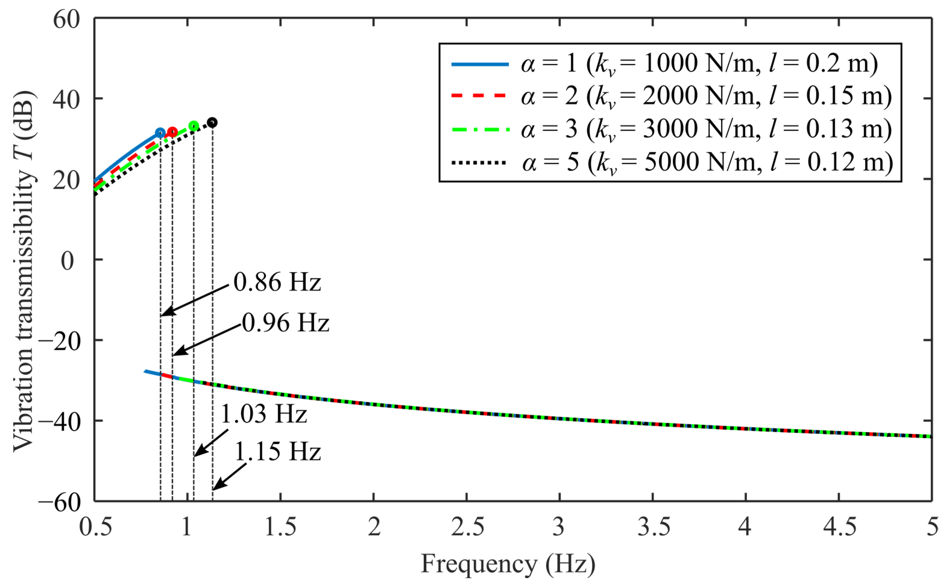
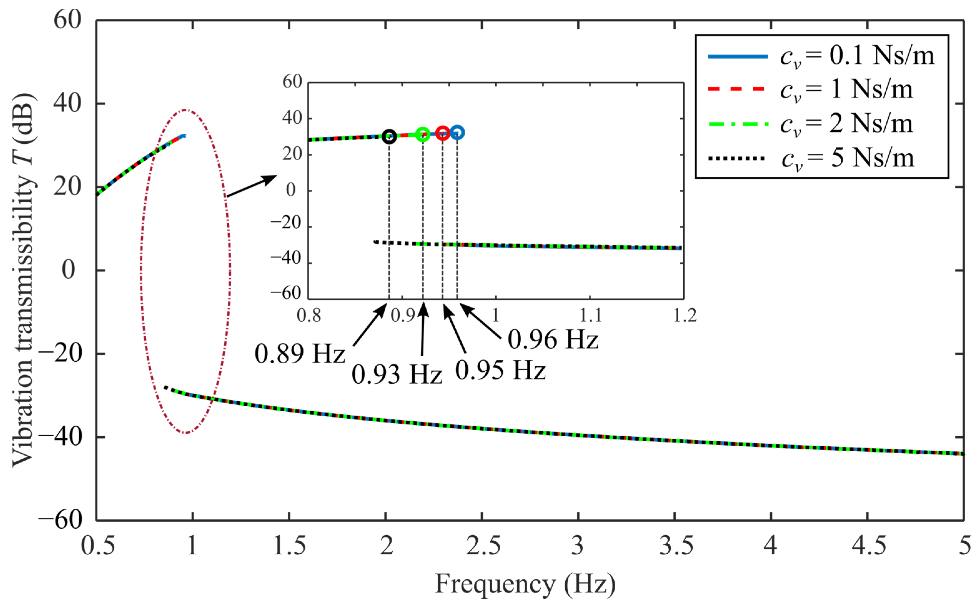
5.1. Comprehensive Study of Vibration Isolation
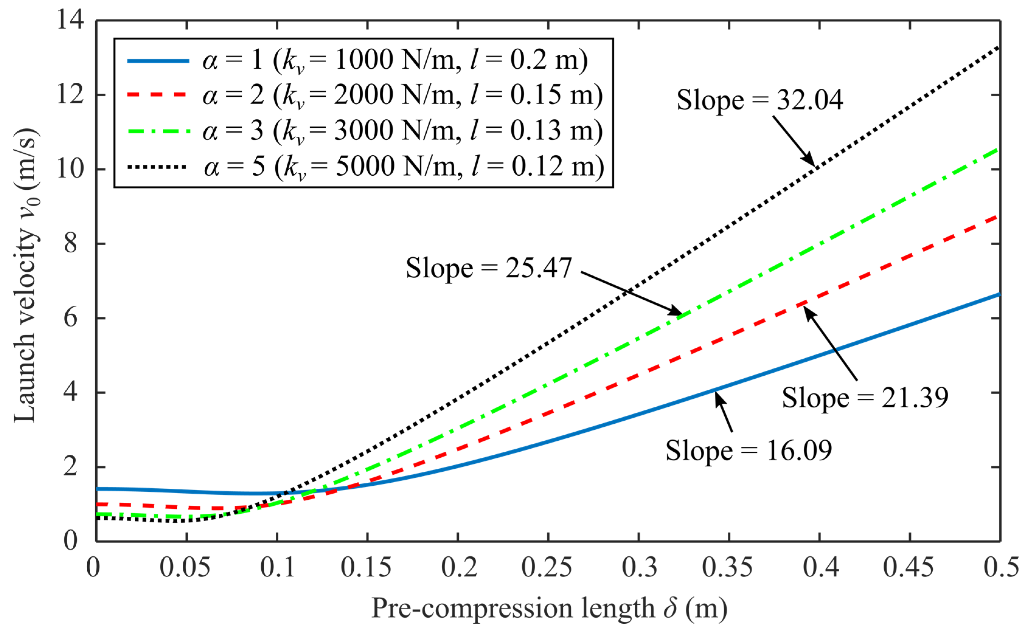
5.2. Comprehensive Study of Launch Velocity
6. Conclusions
Author Contributions
Funding
Institutional Review Board Statement
Informed Consent Statement
Data Availability Statement
Conflicts of Interest
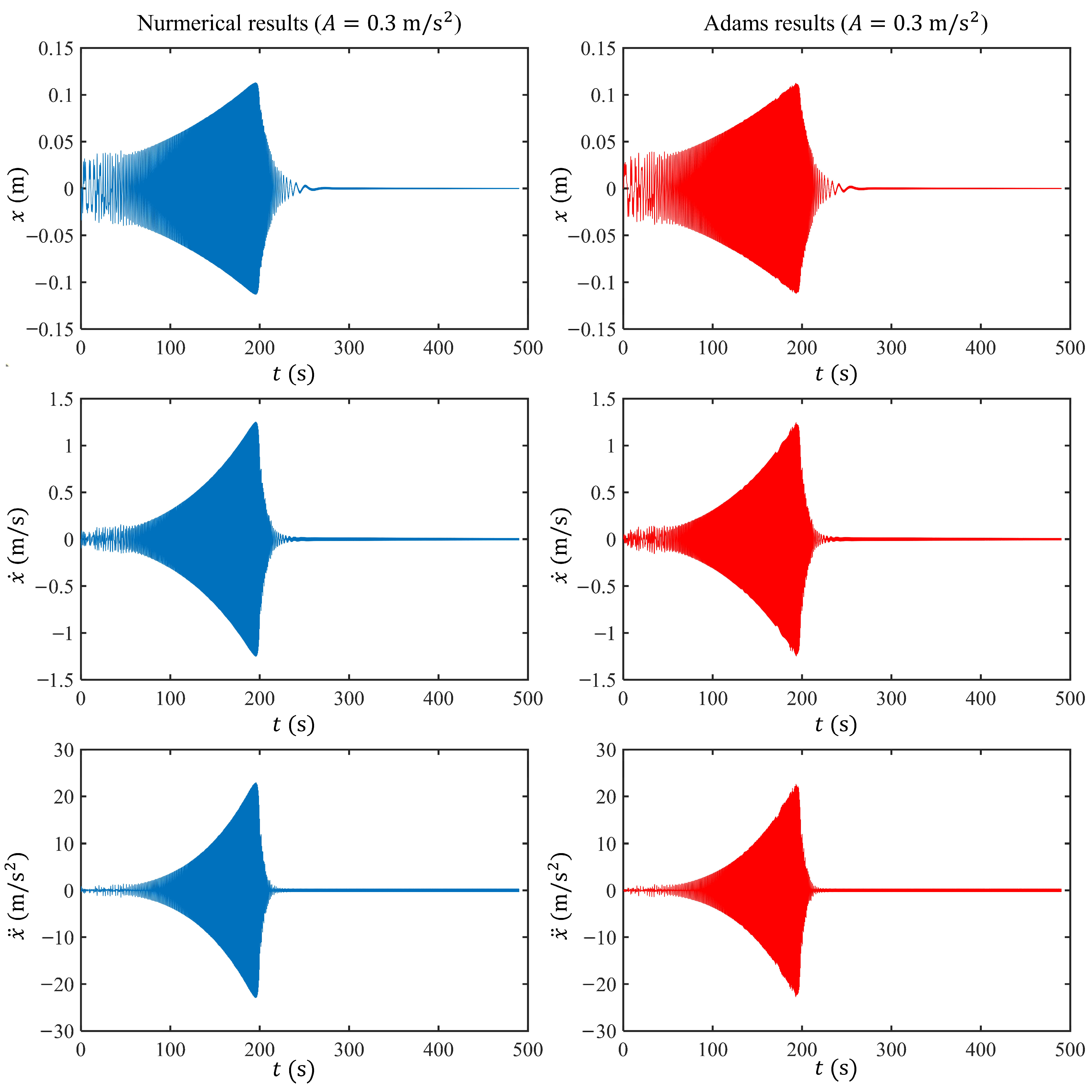
Appendix A. Model Validation Using the MSC Adams Software
References
- Li, W.-J.; Cheng, D.-Y.; Liu, X.-G.; Wang, Y.-B.; Shi, W.-H.; Tang, Z.-X.; Gao, F.; Zeng, F.-M.; Chai, H.-Y.; Luo, W.-B.; et al. On-orbit service (OOS) of spacecraft: A review of engineering developments. Prog. Aerosp. Sci. 2019, 108, 32–120. [Google Scholar] [CrossRef]
- Chiarelli, M.R.; Borrometi, F.B.; Cipolla, V.; Binante, V.; Abu Salem, K.; Palaia, G. Design and Feasibility Study of Novel Flying Wing Carrier for Launching Small Satellites in Low Earth Orbit. Appl. Sci. 2023, 13, 4712. [Google Scholar] [CrossRef]
- Liu, J.; Zhao, P.; Wu, C.; Chen, K.; Ren, W.; Liu, L.; Tang, Y.; Ji, C.; Sang, X. SIASAIL-I solar sail: From system design to on-orbit demonstration mission. Acta Astronaut. 2022, 192, 133–142. [Google Scholar] [CrossRef]
- Zhao, X.; Zhao, C.; Li, J.; Guan, Y.; Chen, S.; Zhang, L. Research on Design, Simulation, and Experiment of Separation Mechanism for Micro-Nano Satellites. Appl. Sci. 2022, 12, 5997. [Google Scholar] [CrossRef]
- Yan, B.; Yu, N.; Wu, C. A state-of-the-art review on low-frequency nonlinear vibration isolation with electromagnetic mechanisms. Appl. Math. Mech. 2022, 43, 1045–1062. [Google Scholar] [CrossRef]
- Tong, W.; Wei, B.; Moshrefi-Torbati, M.; Zhou, X.; Yurchenko, D.; Yang, K. Investigation of a monostable nonlinear vibration isolator with the inertia-elastic boundary. Commun. Nonlinear Sci. Numer. Simul. 2024, 132, 107887. [Google Scholar] [CrossRef]
- Li, H.; Li, Y.; Li, J. Negative stiffness devices for vibration isolation applications: A review. Adv. Struct. Eng. 2020, 23, 1739–1755. [Google Scholar] [CrossRef]
- Wang, S.; Xin, W.; Ning, Y.; Li, B.; Hu, Y. Design, experiment, and improvement of a quasi-zero-stiffness vibration isolation system. Appl. Sci. 2020, 10, 2273. [Google Scholar] [CrossRef]
- Ye, K.; Ji, J.; Brown, T. Design of a quasi-zero stiffness isolation system for supporting different loads. J. Sound Vib. 2020, 471, 115198. [Google Scholar] [CrossRef]
- Zhao, F.; Ji, J.; Ye, K.; Luo, Q. An innovative quasi-zero stiffness isolator with three pairs of oblique springs. Int. J. Mech. Sci. 2021, 192, 106093. [Google Scholar] [CrossRef]
- Wen, G.; He, J.; Liu, J.; Lin, Y. Design, analysis and semi-active control of a quasi-zero stiffness vibration isolation system with six oblique springs. Nonlinear Dyn. 2021, 106, 309–321. [Google Scholar] [CrossRef]
- Gatti, G. A nonlinear quasi-zero stiffness vibration isolator with quintic restoring force characteristic: A fundamental analytical insight. J. Vib. Control 2023, 1–14. [Google Scholar] [CrossRef]
- Gatti, G.; Svelto, C. Exploiting nonlinearity for the design of linear oscillators: Application to an inherently strong nonlinear X-shaped-spring suspension. Mech. Syst. Signal Process. 2023, 197, 110362. [Google Scholar] [CrossRef]
- Liu, T.; Li, A.; Zhang, H. Quasi-zero stiffness interval optimization design and dynamics analysis of a new bi-directional horizontal isolation system. Mech. Syst. Signal Process. 2024, 206, 110852. [Google Scholar] [CrossRef]
- Liu, C.; Yu, K. Design and experimental study of a quasi-zero-stiffness vibration isolator incorporating transverse groove springs. Arch. Civ. Mech. Eng. 2020, 20, 67. [Google Scholar] [CrossRef]
- Yan, G.; Zou, H.-X.; Wang, S.; Zhao, L.-C.; Gao, Q.-H.; Tan, T.; Zhang, W.-M. Large stroke quasi-zero stiffness vibration isolator using three-link mechanism. J. Sound Vib. 2020, 478, 115344. [Google Scholar] [CrossRef]
- Chai, Y.; Jing, X.; Chao, X. X-shaped mechanism based enhanced tunable QZS property for passive vibration isolation. Int. J. Mech. Sci. 2022, 218, 107077. [Google Scholar] [CrossRef]
- Han, H.; Sorokin, V.; Tang, L.; Cao, D. A nonlinear vibration isolator with quasi-zero-stiffness inspired by Miura-origami tube. Nonlinear Dyn. 2021, 105, 1313–1325. [Google Scholar] [CrossRef]
- Zhou, X.; Zhao, D.; Sun, X.; Yang, X.; Zhang, J.; Ni, T.; Tang, K. An asymmetric quasi-zero stiffness vibration isolator with long stroke and large bearing capacity. Nonlinear Dyn. 2022, 108, 1903–1930. [Google Scholar] [CrossRef]
- Yan, B.; Yu, N.; Wang, Z.; Wu, C.; Wang, S.; Zhang, W. Lever-type quasi-zero stiffness vibration isolator with magnetic spring. J. Sound Vib. 2022, 527, 116865. [Google Scholar] [CrossRef]
- Liu, Y.; Ji, W.; Gu, H.; Deng, E.; Wang, X.; Song, C. Force transmissibility of a 6-DOF passive quasi-zero stiffness vibration isolation platform. J. Mech. Sci. Technol. 2021, 35, 2313–2324. [Google Scholar] [CrossRef]
- Lan, C.-C.; Yang, S.-A.; Wu, Y.-S. Design and experiment of a compact quasi-zero-stiffness isolator capable of a wide range of loads. J. Sound Vib. 2014, 333, 4843–4858. [Google Scholar] [CrossRef]
- Fulcher, B.A.; Shahan, D.W.; Haberman, M.R.; Seepersad, C.; Wilson, P.S. Analytical and Experimental Investigation of Buckled Beams as Negative Stiffness Elements for Passive Vibration and Shock Isolation Systems. J. Vib. Acoust. 2014, 136, 031009. [Google Scholar] [CrossRef]
- Liu, X.; Zhao, Q.; Zhang, Z.; Zhou, X. An experiment investigation on the effect of Coulomb friction on the displacement transmissibility of a quasi-zero stiffness isolator. J. Mech. Sci. Technol. 2019, 33, 121–127. [Google Scholar] [CrossRef]
- Zheng, Y.; Zhang, X.; Luo, Y.; Zhang, Y.; Xie, S. Analytical study of a quasi-zero stiffness coupling using a torsion magnetic spring with negative stiffness. Mech. Syst. Signal Process. 2018, 100, 135–151. [Google Scholar] [CrossRef]
- Yan, B.; Ma, H.; Zhao, C.; Wu, C.; Wang, K.; Wang, P. A vari-stiffness nonlinear isolator with magnetic effects: Theoretical modeling and experimental verification. Int. J. Mech. Sci. 2018, 148, 745–755. [Google Scholar] [CrossRef]
- Wang, Y.; Jing, X.; Dai, H.; Li, F.-M. Subharmonics and ultra-subharmonics of a bio-inspired nonlinear isolation system. Int. J. Mech. Sci. 2019, 152, 167–184. [Google Scholar] [CrossRef]
- Wang, Y.; Jing, X.; Guo, Y. Nonlinear analysis of a bio-inspired vertically asymmetric isolation system under different structural constraints. Nonlinear Dyn. 2019, 95, 445–464. [Google Scholar] [CrossRef]
- Salvatore, A.; Carboni, B.; Lacarbonara, W. Nonlinear dynamic response of an isolation system with superelastic hysteresis and negative stiffness. Nonlinear Dyn. 2022, 107, 1765–1790. [Google Scholar] [CrossRef]
- Zhang, F.; Xu, M.; Shao, S.; Xie, S. A new high-static-low-dynamic stiffness vibration isolator based on magnetic negative stiffness mechanism employing variable reluctance stress. J. Sound Vib. 2020, 476, 115322. [Google Scholar] [CrossRef]
- Dai, H.; Cao, X.; Jing, X.; Wang, X.; Yue, X. Bio-inspired anti-impact manipulator for capturing non-cooperative spacecraft: Theory and experiment. Mech. Syst. Signal Process. 2020, 142, 106785. [Google Scholar] [CrossRef]
- Carrella, A.; Brennan, M.J.; Waters, T.P. Static analysis of a passive vibration isolator with quasi-zero-stiffness characteristic. J. Sound Vib. 2007, 301, 678–689. [Google Scholar] [CrossRef]


| Properties | Proposed Design | Linear Design |
|---|---|---|
| 10 kg | 10 kg | |
| 1000 N/m | 2000 N/m (Equivalent stiffness) | |
| 1 Ns/m | 2 Ns/m (Equivalent damping) | |
| 2000 N/m | None | |
| 0.1 Ns/m | ||
| 0.15 m | ||
| 0.1 m |
| Properties | Set 1 | Set 2 | ||
|---|---|---|---|---|
| Proposed Design | Linear Design | Proposed Design | Linear Design | |
| 10 kg | 10 kg | 10 kg | 10 kg | |
| 1000 N/m | 1000 N/m | 1500 N/m | 1500 N/m | |
| 1 Ns/m | 1 Ns/m | 1 Ns/m | 1 Ns/m | |
| 2000 N/m | None | 3000 N/m | None | |
| 0.1 Ns/m | 0.1 Ns/m | |||
| 0.15 m | 0.15 m | |||
| 0.1 m | 0.1 m | |||
Disclaimer/Publisher’s Note: The statements, opinions and data contained in all publications are solely those of the individual author(s) and contributor(s) and not of MDPI and/or the editor(s). MDPI and/or the editor(s) disclaim responsibility for any injury to people or property resulting from any ideas, methods, instructions or products referred to in the content. |
© 2024 by the authors. Licensee MDPI, Basel, Switzerland. This article is an open access article distributed under the terms and conditions of the Creative Commons Attribution (CC BY) license (https://creativecommons.org/licenses/by/4.0/).
Share and Cite
Zhou, X.; Tong, W.; Dai, L.; Wei, B. Vibration Isolation and Launch Performance Enhancement of the Spacecraft In-Orbit Launch Design Using the Nonlinear Dynamic Feature. Appl. Sci. 2024, 14, 4250. https://doi.org/10.3390/app14104250
Zhou X, Tong W, Dai L, Wei B. Vibration Isolation and Launch Performance Enhancement of the Spacecraft In-Orbit Launch Design Using the Nonlinear Dynamic Feature. Applied Sciences. 2024; 14(10):4250. https://doi.org/10.3390/app14104250
Chicago/Turabian StyleZhou, Xu, Weihao Tong, Lu Dai, and Boyuan Wei. 2024. "Vibration Isolation and Launch Performance Enhancement of the Spacecraft In-Orbit Launch Design Using the Nonlinear Dynamic Feature" Applied Sciences 14, no. 10: 4250. https://doi.org/10.3390/app14104250
APA StyleZhou, X., Tong, W., Dai, L., & Wei, B. (2024). Vibration Isolation and Launch Performance Enhancement of the Spacecraft In-Orbit Launch Design Using the Nonlinear Dynamic Feature. Applied Sciences, 14(10), 4250. https://doi.org/10.3390/app14104250