Article

Thermoforming Simulation of Woven Carbon Fiber Fabric/Polyurethane Composite Materials

1
Department of Mechanical Engineering, National Yunlin University of Science and Technology, Yunlin 64002, Taiwan
2
Department of Civil and Construction Engineering, National Yunlin University of Science and Technology, Yunlin 64002, Taiwan
3
College of Future, Bachelor Program in Interdisciplinary Studies, National Yunlin University of Science and Technology, Yunlin 64002, Taiwan
4
Department of Mechanical and Computer Aided Engineering, Feng Chia University, Taichung 40724, Taiwan
*
Author to whom correspondence should be addressed.
Appl. Sci. 2024, 14(1), 445; https://doi.org/10.3390/app14010445
Submission received: 1 December 2023 / Revised: 28 December 2023 / Accepted: 29 December 2023 / Published: 3 January 2024
(This article belongs to the Special Issue Advanced Finite Element Method and Its Applications)

Abstract

:
A finite element simulation was utilized in this work to analyze the thermoforming process of woven carbon fiber fabric/polyurethane thermoplastic composite sheets. In the simulation that may be classified as a discrete method, the woven carbon fiber fabric was treated as an undulated fill yarn crossed over an undulated warp yarn, and the resin was considered separately. Then, they were combined to represent the composite sheets. To verify this simulation, bias extension tests under three constant temperatures were executed. After that, the composite was thermoformed into a U-shaped structure and small luggage. From the bias extension tests, the finite element simulation and material properties of the fiber and resin were confirmed. From the comparison of the thermoformed products, the present simulation could provide the deformed profile and fiber-included angles and has good agreement with the experiment. The results also indicate that the stacking sequences of [(0°/90°)]4 and [(+45°/−45°)]4 have quite different product profiles and fiber-included angles.

1. Introduction

Composite materials are popular candidates for weight saving in structure components that are applied in aerospace, automobile, sports, and other industries because they have high stiffness/weight and strength/weight ratios. Currently, thermoset composite materials are dominant in these applications, considering their good mechanical properties. Even though thermoplastic composite materials have no competitive stiffness and strength, they have very good toughness and recyclability, a fast forming cycle, and an excellent shelf life. Based on these advantages, thermoplastic composite materials have started to become a better choice in some situations. To circumvent the high viscosity and cost, thermoplastic composite materials may be used in a semi-finished form, such as sheets, for further manufacturing processes. Therefore, forming processes like thermoforming, hydroforming, vacuum forming, rubber pad forming, and diaphragm forming are possible choices [1,2]. The main considerations for the selection of forming processes are the cost of the mold and the quality of the final part. Matched-die press forming, otherwise called thermoforming, is a suitable selection for thermoplastic composites because it can be easily accessed, automated, and used to make components with complicated shapes.
In the thermoforming process, the thermoplastic blank is heated to a temperature between the glass transition temperature and the melting temperature such that it is soft. Then, the blank is pressed with molds having complicated shapes, and the solidification is complete after the cooling process is finished. Generally, thermoforming is a simple, fast, and high-deformation process, and it can be automated. Therefore, it draws widespread interest in thermoplastic composites. For instance, Striewe et al. [3] thermoformed a woven glass fabric/polyamide 6 thermoplastic blank into a three-dimensional hat profile at around 270 °C. Then, it was bonded with a closing plate into a crash box for crashworthiness investigation. Behrens et al. [4] developed a fully automated forming process to construct the same glass fiber-reinforced thermoplastic composite sheet at 260 °C into a down-scaled battery tray for a plug-in-hybrid automotive vehicle. Using two subsequent forming steps and local heating of the structure, Maron et al. [5] could manufacture a thermoplastic composite shaft with an integrated flange from a semi-finished tube at a temperature range that is higher than the melting point.
Because thermoforming is a temperature-related process, to obtain a product with good quality, the process parameters, especially those related to temperature, need to be carefully selected. Lee et al. [6] considered the effect of cooling rates on the mechanical properties of the thermoformed glass fiber-reinforced polypropylene composites. Judging from the final dimensions of the products, Han et al. [7] tried to find the optimal molding temperature for forming the carbon fiber/polyphenylene sulfide sheets into V-shaped parts. To prevent the wrinkling of the glass fiber-reinforced polypropylene composite laminates, the effect of the stacking sequence at the drawing stage [8] was studied. For the products having complicated double curvatures, the various thermoplastics and fiber orientations of thermoplastic composite blanks and the fixed method of mold were experimentally proven to be very important [9]. In addition, forming rate and blank holding pressure are also important parameters. Therefore, thermoforming is a very complicated, nonlinear, and multivariable process.
To find the optimal parameters for the thermoforming process of thermoplastic composite materials, finite element simulation is a better choice instead of theoretical modeling. The current methods of simulating this thermoforming process can be roughly classified into the continuous method, discrete method, and semi-discrete method. The continuous method [10,11,12,13,14,15,16,17] treats thermoplastic composites as continuous, uniform, and macroscopic materials, using conventional shell or membrane elements. This method considers the shear and bending behavior of the combination of fiber and resin, but in fact, the large sliding and rotation between fibers are not considered. In comparison, the discrete method [18,19,20] treats the woven fabric as a micro-mechanical materials model that has the behavior of fiber reorientation, a trellis mechanism, and viscoelasticity. In addition, the resin is modeled separately and combined with the fabric model to simulate the thermoforming process of thermoplastic composites. This method covers the full mobility of the fabric’s microstructure and effectively represents the macroscopic behavior of the composite. Through this model, the influence of different material properties on macroscopic behavior can be studied. Furthermore, this method can also reveal large deformation, localization, and damage-related behaviors. However, because of the micro-mechanical models, a lot of fiber and resin parameters are needed, and some of them may be difficult to accurately obtain. One alternative selection to maintain the advantage and avoid the disadvantages of the above two methods is the semi-discrete method [21,22], in which special continuous elements are developed and affected by the micro-mechanical behavior.
The most important part of the discrete method is to describe the movement of both the fill yarn and the warp yarn in a fabric. A hyperelastic model was proposed by Charmetant et al. [23] to predict the deformed geometry of a woven fabric under external loads. They conducted the experiments of both shear test and biaxial tension to validate the model. A special hexahedral finite element, in which a hyperelastic constitutive law was used to simulate the transverse properties of segment yarns, was developed by De Luycher et al. [24]. Under a non-isothermal forming process, Schommer et al. [25] used a hybrid-unit-cell model in which beam elements and shell elements were combined to predict the fiber behavior. For the stamping of a preform using a spherical punch, Sidhu et al. [26] demonstrated the applicability of a combination model consisting of truss elements for the tow scissoring and sliding and shell elements for the tow friction and angle jamming.
In this work, the thermoforming behavior of composite structures composed of woven carbon fiber fabric/polyurethane was simulated by a finite element method and compared with experimental results. To characterize the thermoplastic composite, differential scanning calorimeter and dynamic mechanical analyses were performed. To simulate the deformation conditions of the composite sheets, the above-mentioned discrete method, wherein the woven carbon fabric and resin were described using different material models, was utilized. To verify this finite element simulation, bias extension tests under three constant temperatures were executed and compared numerically and experimentally. After that, the woven carbon fiber fabric/polyurethane thermoplastic composite sheets were pressed into a U-shaped structure or small luggage under temperature and pressure control. The deformed profile and fiber-included angles were the main points for the comparison between the simulation and experiment.

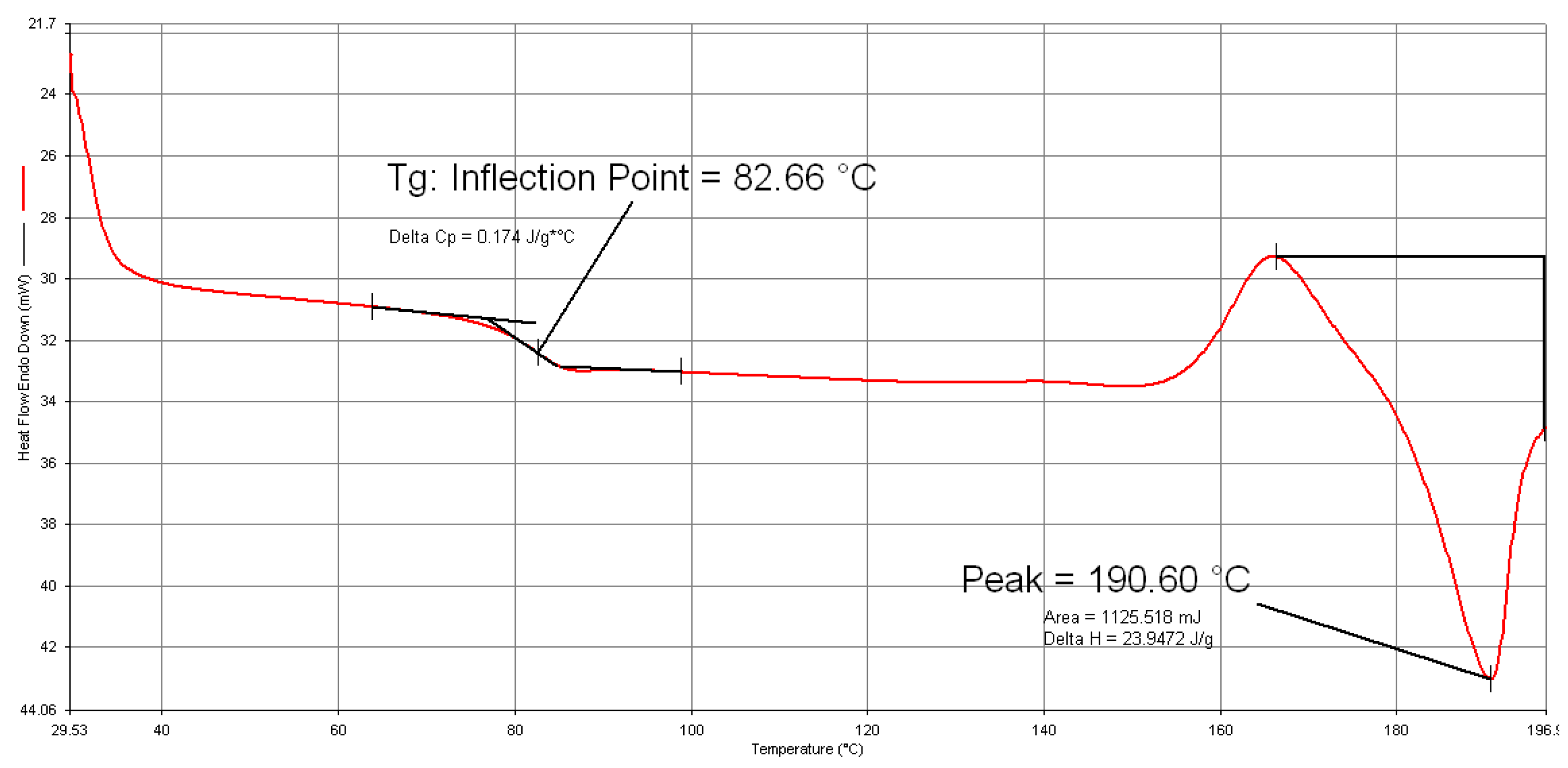
2. Material Characterization and Thermoforming

The thermoplastic composite blanks consisted of 2 × 2 twill woven carbon fabrics (CFs) and thermoplastic polyurethane (TPU) and were created by Formosa Plastics Corporation. The fabrics were woven with TAIRYFIL TC-300 3K carbon fiber yarns. A differential scanning calorimeter was used to test the thermoplastic composite blank to understand its temperature properties. The temperature increasing rate was set to be 5 °C/min. From the obtained results, the glass transition temperature was about 83 °C and the melting temperature was about 190 °C, as shown in Figure 1. Furthermore, this composite blank was tested using a dynamic mechanical analysis under a 2 °C/min temperature increasing rate. From this test, the Young’s modulus of the composite material could be obtained; then, the Young’s modulus of the thermoplastic polyurethane was deduced. In Figure 2, the variation of Young’s modulus of thermoplastic polyurethane was shown with respect to temperature. There was a slight variation in the modulus between 120 °C to 200 °C because of the variation from the original data. These variations had less effect on the simulation results.
Two structures created from thermoplastic composites using thermoforming were considered in the present work. The first one was named the U-shaped structure, and the second was called small luggage. To thermoform the U-shaped structure, punch and die processing was used as shown in Figure 3a,b. Due to its simple shape, the manufacture of U-shaped structures could be considered as one-dimensional thermoforming. The forming conditions for U-shaped structures are shown in Figure 4. The thermoplastic composite blank had a dimension of 255 × 120 × 1 mm, and it had four same layers. The forming temperature of the thermoplastic composite was chosen to be 170 °C, which was above the glass transition temperature and under the melting temperature. The temperatures of the punch and the die were set to 100 °C and 160 °C, respectively, and the reason for these temperatures was due to trial and error and in order to have better part quality. The forming rate and the final forming pressure were 25 mm/s and 40 kg/cm2, respectively. A blank holder with a pressure of 10 kg/cm2 was used. These forming conditions were selected by trial and error to avoid rough surfaces, wrinkles, and fractures. Two types of stacking sequences were utilized to consider the influence of the fiber angle on the final products. They were [(0°/90°)]4 and [(+45°/−45°)]4, in which the parenthesis represented a thermoplastic composite layer. When the thermoplastic composite blank was laid on the die, an infrared heater was used to increase its temperature to the set value. Then, the forming process was conducted. The pressure was kept constant until the temperature of the workpiece was naturally cooled to room temperature. After that, the product was demolded.
For the small luggage, the punch and die are shown in Figure 5. There are no detailed dimensions because of their complicated structures. In this case, the thermoplastic composite blank had a dimension of 313.5 × 209 × 1 mm, and the dimension of the final product was about 203 × 130 × 48 mm, where the product thickness was still close to 1 mm. The two types of stacking sequences, [(0°/90°)]4 and [(+45°/−45°)]4, were also considered. The forming conditions for the small luggage were similar to those for the U-shaped structures except that the blank holding pressure was 10 kg/cm2 and the final forming pressure was 50 kg/cm2. After forming, a water cooling system was applied, and the composite product was demolded at room temperature.

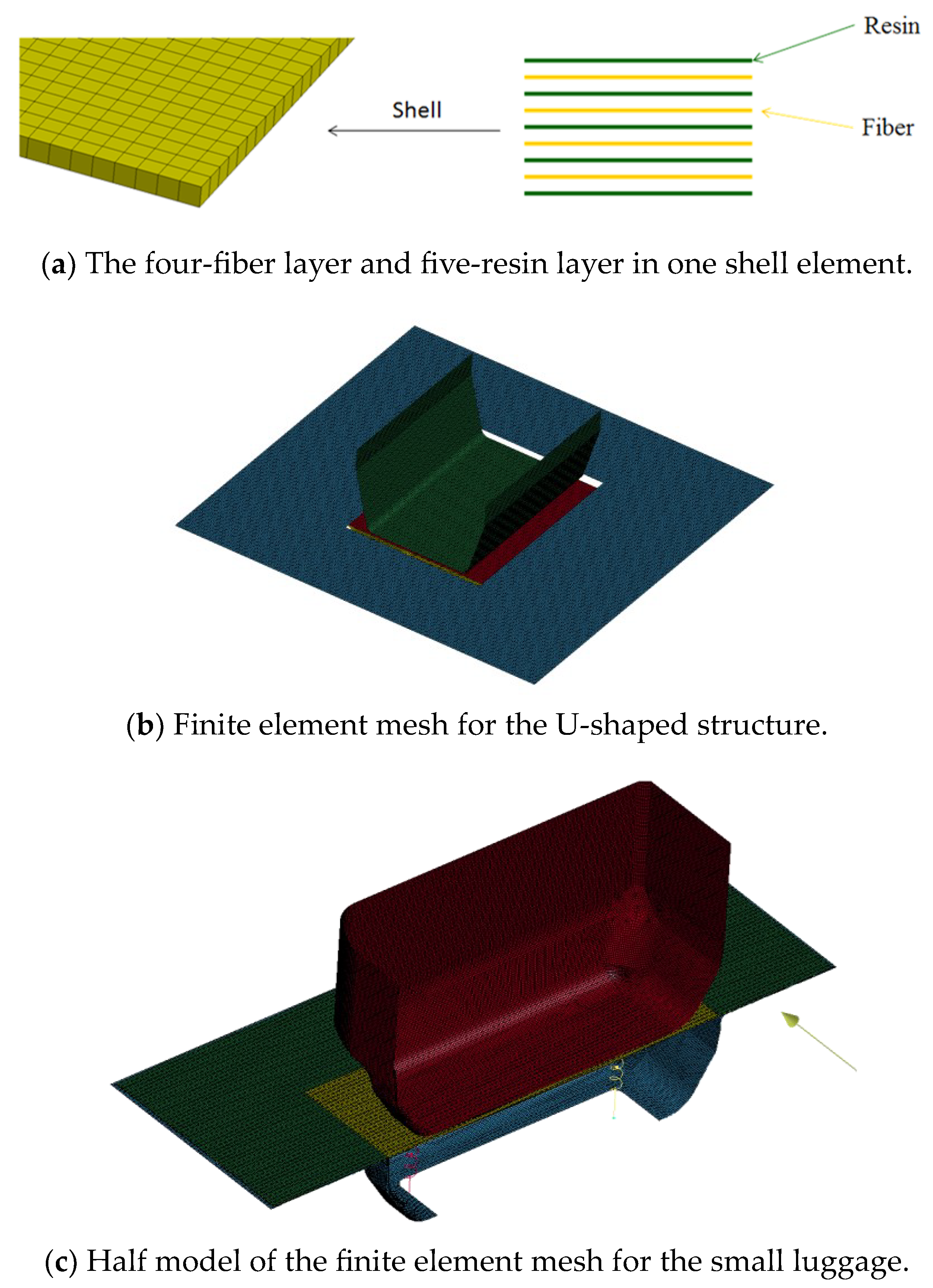
3. Finite Element Simulation

The simulation of the thermoforming process by a finite element method was executed using the commercial software LS-DYNA R10.0. To consider the fiber angle change during the thermoforming process, the above-mentioned discrete method was adopted under the explicit mode. A computational micro-mechanical material model was implemented in a material card, MAT 234 in LS-DYNA, for the woven fiber fabric, and it was originally from Tabiel et al. [18]. In this approach, the representative volume technique extracted from the deformed pattern of the loosely woven fabric material model consisted of an undulated fill yarn crossed over an undulated warp yarn. Then, they were simplified and represented as a pin-joint mechanism of viscoelastic bars connected by a rigid link. This mechanism described the in-plane rotation of the yarns as a trellis mechanism and described the straightening of the undulated yarns. The orthogonal yarns in loose fabric were allowed to rotate until the lateral contact between the neighbor yarns caused the locking phenomenon. The behavior of the yarns was considered viscoelasticity, in which a Kelvin–Voight model was combined with a Maxwell model without the dashpot. Finally, to transform the stress of the yarns to the stress of the element, the representative volume cell was considered to be parallelepiped. There are a lot of carbon fiber parameters that need to be input in this discrete approach. To be concise, only some main material parameters are shown in Table 1. To describe the behavior of the thermoplastic resin in LS-DYNA, the material card MAT 004 was selected, because this card is suitable for elasticity, plasticity, and thermal analysis. In this work, the resin was simplified to be under elasticity, but its Young’s modulus could be varied with temperature, as illustrated in Figure 2. The density and Poisson’s ratio of the resin were 1.2 g/cm3 and 0.45, respectively.
The thermoplastic composite blank, which had four layers of fiber fabrics, was treated as one object, which was meshed by shell elements. Only one shell element was used along the thickness direction. In the discrete approach, each shell element included five resin layers and four fiber fabric layers that were alternatively interlaced, as illustrated in Figure 6a. The thickness of the resin layer and the fabric layer in the element was calculated from the 1 mm total thickness of the blank and the fiber volume fraction of 0.4. Hence, they were 0.12 mm and 0.1 mm, respectively. To have a suitable layer number combination for the blank, other combinations were also discussed, and the above nine-layer combination had the best simulation results [11]. Figure 6b shows the mesh of the blank with the U-shaped punch and the blank holder, in which 1 × 1 mm shell elements were used. For the small luggage, because of the symmetry, only half of the system was meshed as shown in Figure 6c, and all shell elements were also 1 × 1 mm. To reduce the calculation in these two cases, the punch, the blank holder, and the die were considered rigid bodies, even though a Young’s modulus of 210 GPa, Poisson’s ratio of 0.3, and density of 7.83 g/cm3 were assigned. The conditions of the thermoforming process are described in Figure 4. As is shown, the temperatures of different parts were different, and there was heat conduction. Therefore, this structural forming simulation was coupled with the transient thermal analysis, and the final temperature of all parts was reduced to 25 °C after the simulation. In addition, due to the contact of different parts, the friction coefficient was 0.2 for the static case and 0.1 for the dynamic case.

4. Results and Discussion

4.1. Bias Extension Test

To verify the finite element analysis for the deformation behavior of the thermoplastic composite and its relation with temperature, bias extension tests, which were originally applied to characterize the shear behavior of fiber fabric under uniaxial loading, were conducted. In this test, the shear stress distribution is not uniform for the whole specimen due to the clamped boundary conditions, and only the central part of the specimen could be considered as under pure shear stress. In the present work, instead of carbon fiber fabric, the carbon fiber fabric/polyurethane thermoplastic composite with [(+45°/−45°)]4 under constant temperature was subjected to a uniaxial tension test with a loading rate of 2 mm/min using an Instron 5982 device with a temperature control cabinet. The obtained force–displacement curve will be compared with the finite element results. The same shell element with nine layers was used to mesh the composite with the size of 1 × 1 mm. The end tab was added and modeled with a rigid body. Instead of shell elements, solid elements were used to mesh the end tab and had the size of 1 × 1 × 1 mm. The comparison between the experiment and the simulation is shown in Figure 7, in which three constant temperatures, including 50, 80, and 100 °C, are considered. The solid lines are from experiments, and their drops at the end do not represent the failure of the specimen but just the stop of the tension test. For the two cases of 80 °C and 100 °C, the curve from the experiment and the simulation are almost identical, while the curve for the case of 50 °C has a slight deviation between the experiment and the simulation. This may come from the difference in the Young’s modulus of the resin at low temperatures between the experiment and the simulation, which has a larger effect on the behavior of the thermoplastic composite as compared with that at high temperatures; although, the difference of the force–displacement curve at 50 °C is still reasonable. Therefore, these result comparisons indicate that the simulation and experiment curves have a reasonable agreement, and this also implies the applicability of the current finite element analysis with the coupled structural thermal behavior.

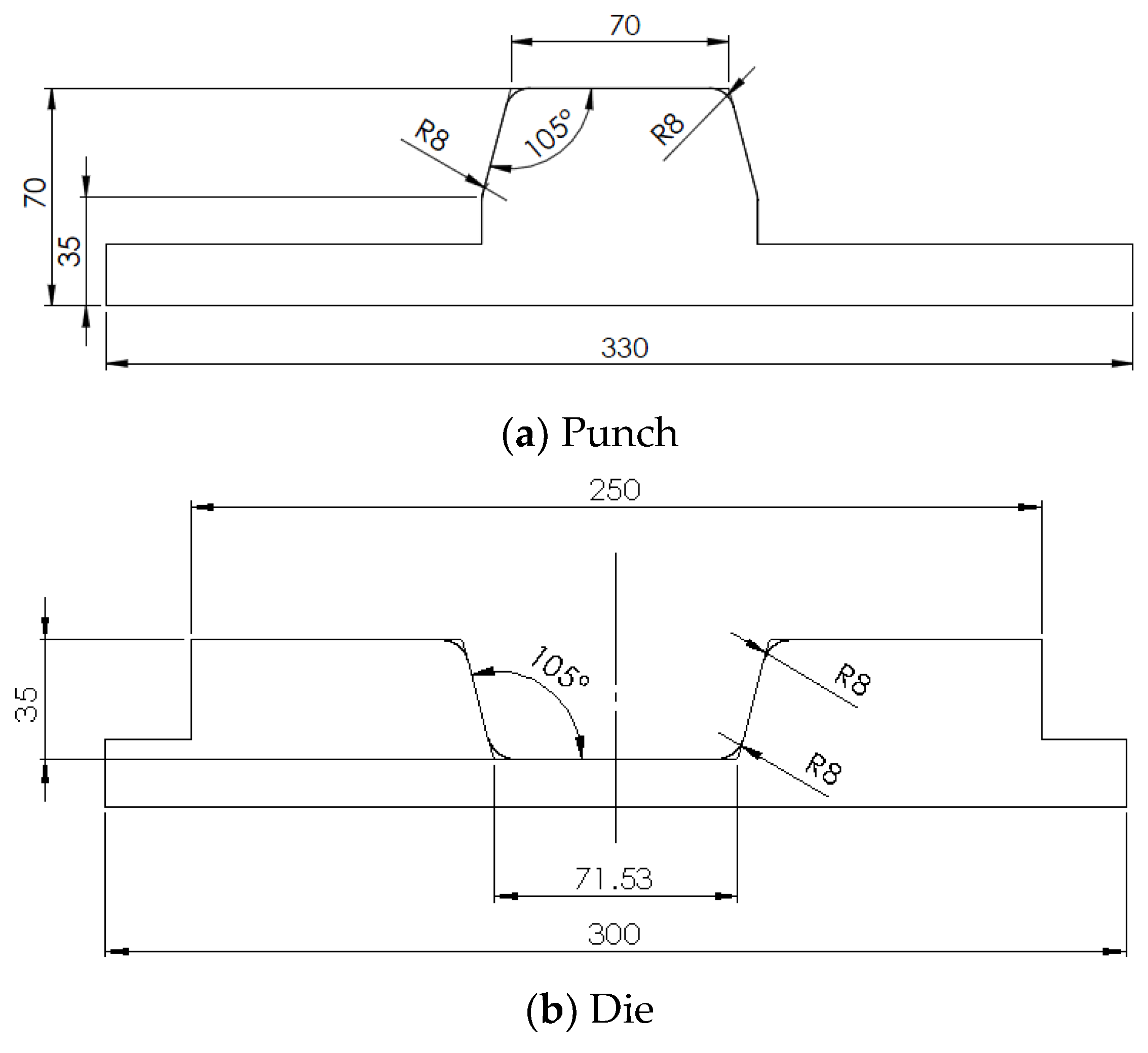
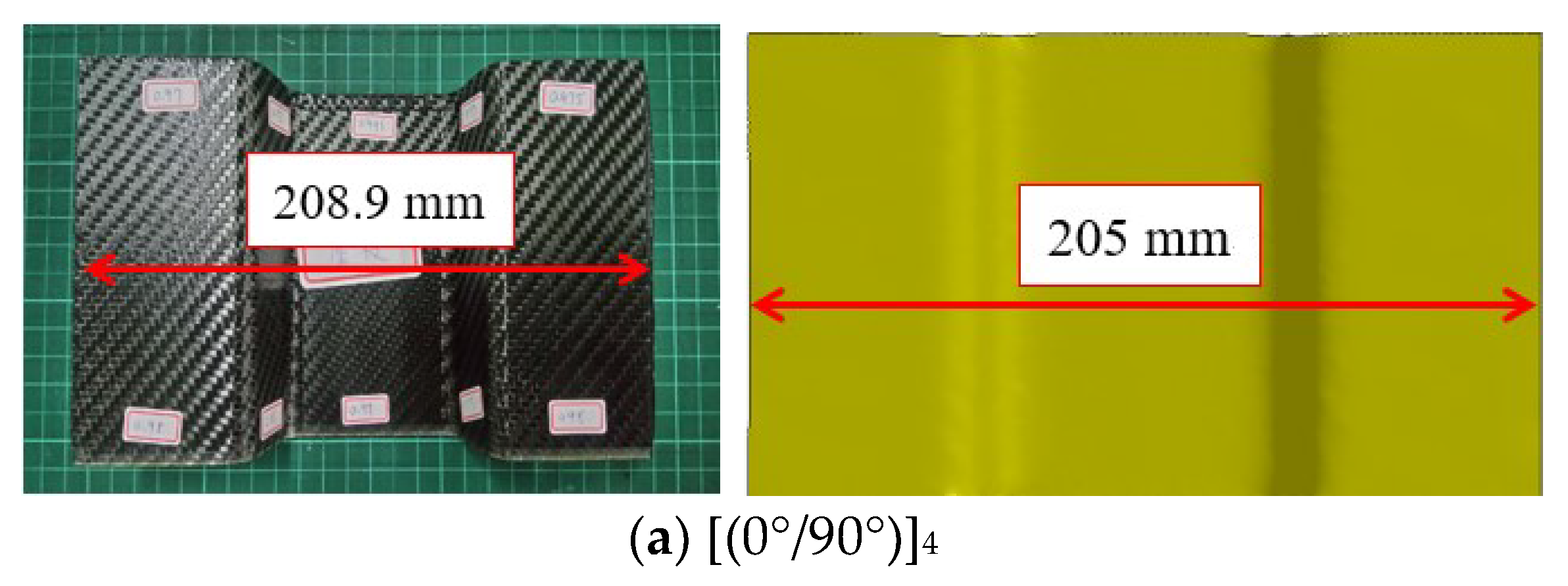
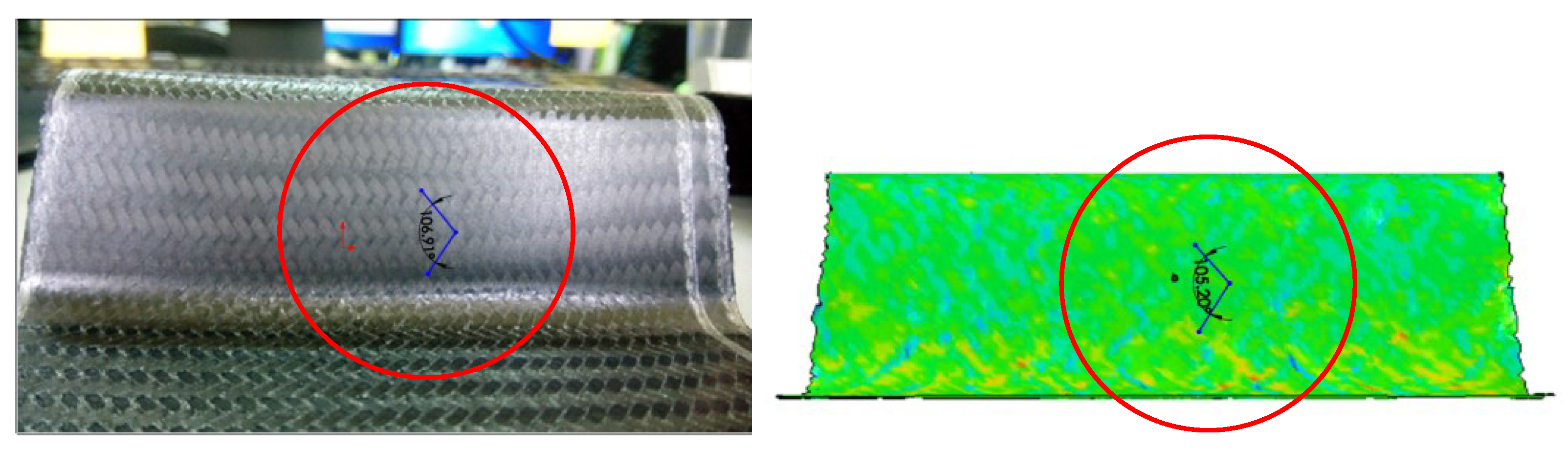
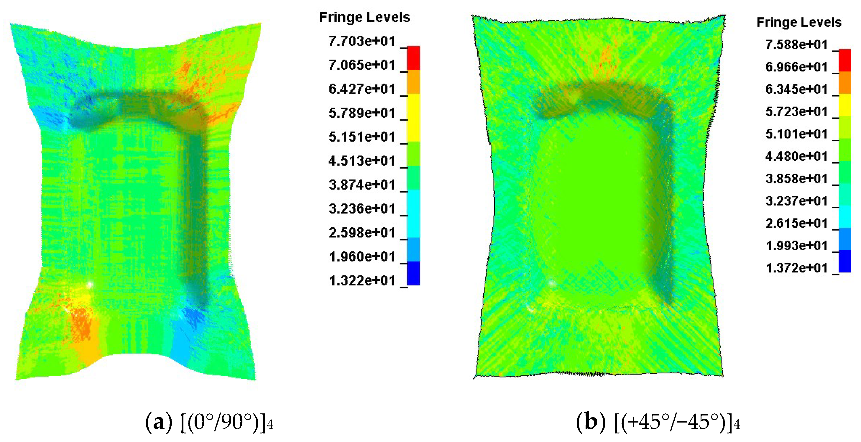
4.2. U-Shaped Structure
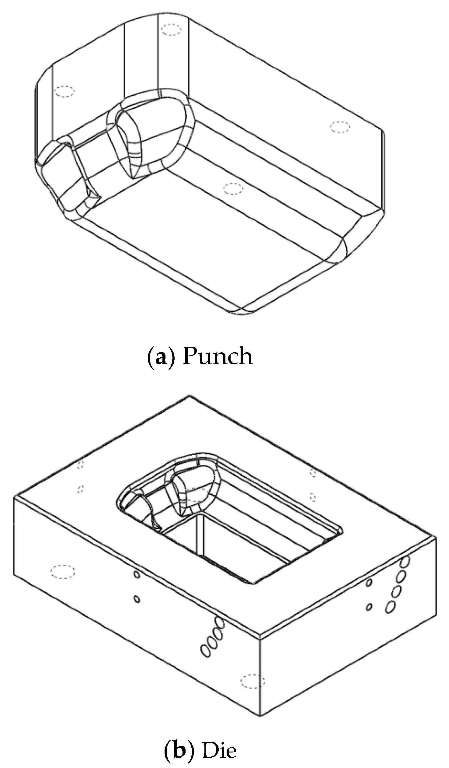
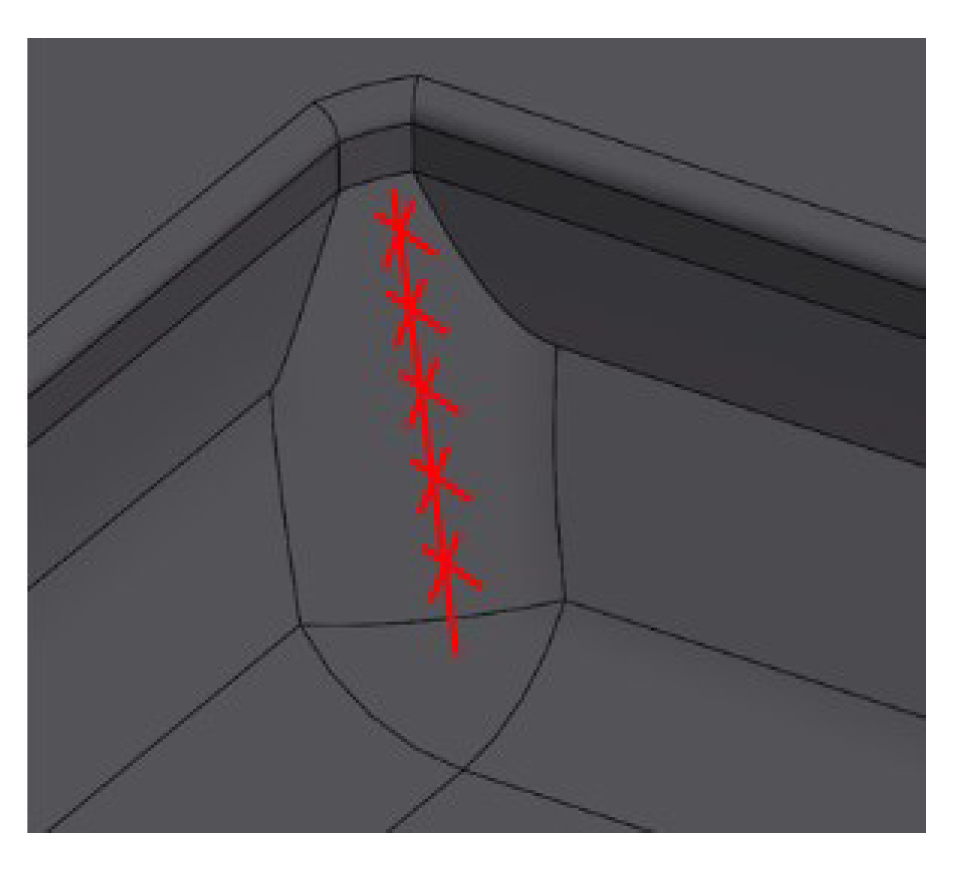
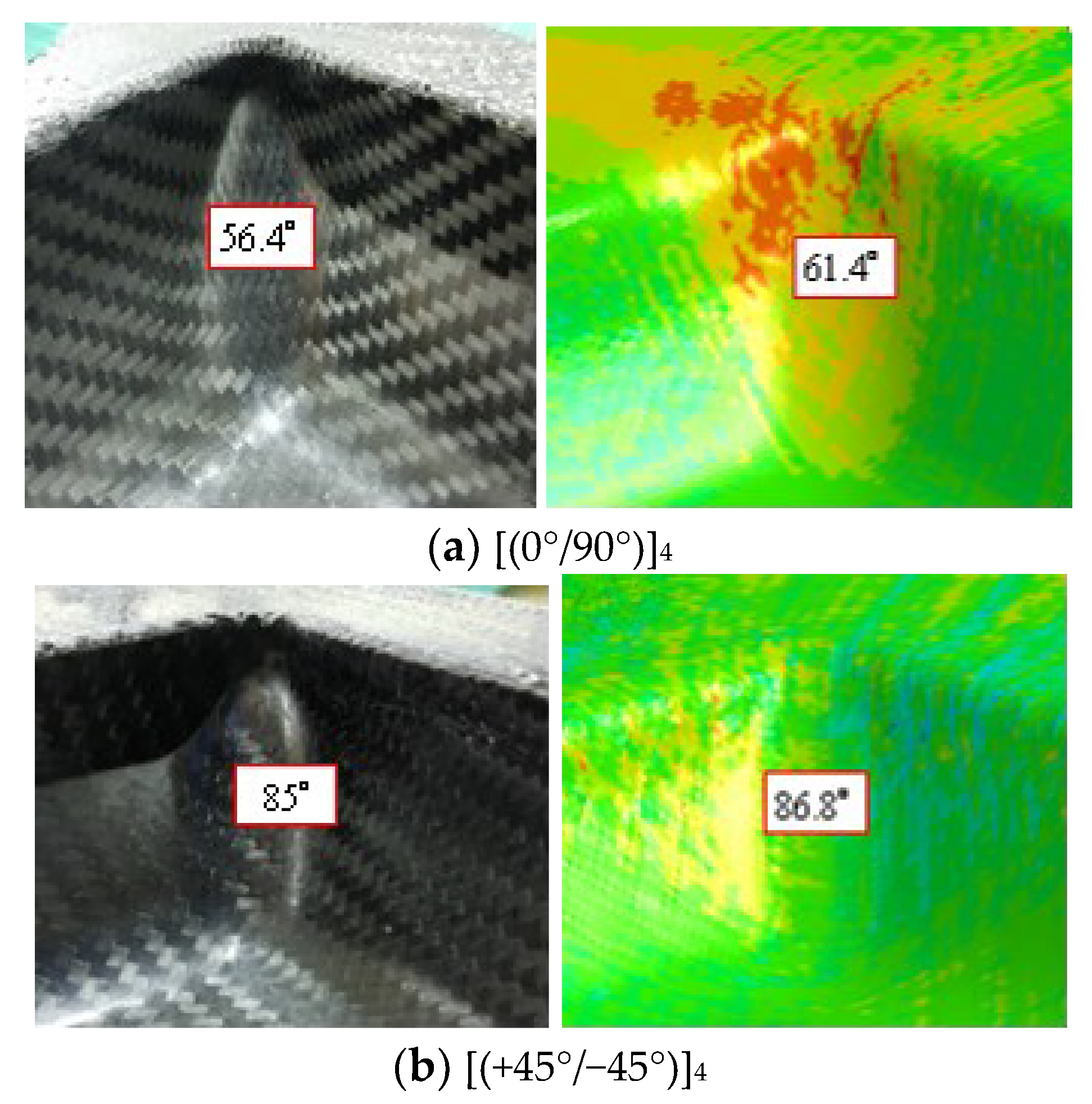
As mentioned, the thermoforming of U-shaped structures is like a one-dimensional deformation, especially for the [(0°/90°)]4 case. The geometric profile comparison of this [(0°/90°)]4 workpiece between the experiment and the simulation is shown in Figure 8a. As is shown, both results have a uniform and nonchanged width and only the length of the product is reduced due to the indentation. The original length of the blank is 255 mm, and it becomes 208.9 mm from the experiment and 205 mm from the simulation. This difference is less than 2% and could be considered as small. As for the [(+45°/−45°)]4 case, the profile change from the original composite rectangle blanket is slightly large, as shown in Figure 8b. The center of the product, which is also the bottom of the U shape, has a uniform width. However, the width is reduced from 120 mm to either 102.8 mm for the experiment or 106.6 mm for the simulation. There is a 3.7% difference in the shortest width. The reason for this reduction is the shear deformation, just like the bias extension test. Similarly, both flanges of the U-shaped structure become the sector shape from both the experiment and the simulation, as shown in Figure 8b. Hence, the simulation still has a very similar profile to the experiment.
The comparison of the fiber-included angle is shown in Figure 9 and Figure 10 for both stacking sequence cases. The location to obtain the fiber-included angle is at the wall part of the U-shape as shown. One should note that the fiber-included angles have two values for the woven fabric, and their summation is 180°. For the [(0°/90°)]4 case, the predicted value of the fiber-included angle is 89.60° (or 90.40°) as compared with the measured result of 92.06° (or 87.94°). These two values are very close to the original ones, and the change is small because the extension is along one fiber direction. For the [(+45°/−45°)]4 case, the fiber-included angle encounters a big change after thermoforming. As shown in Figure 10, the measured value is 106.91° (or 73.09°) and the simulation result is 105.20° (or 74.80°). This large change in the fiber-included angle can also be attributed to the bias extension effect. According to the comparison for both the product profile and the fiber-included angle, the finite element analysis in this work could reasonably simulate the deformation behavior of thermoplastic composites under thermoforming.

4.3. Small Luggage

As compared with the U-shaped structures, the small luggage structure could be considered a complicated one. After thermoforming, the geometric profile of the product is very difficult to predict by intuition. The geometric profile comparison for small luggage after thermoforming is shown in Figure 11a,b for both [(0°/90°)]4 and [(+45°/−45°)]4. When the stacking sequence is different, the geometric profile of the product is quite different, as is shown. There are four redundant triangles and four straight mid-lines for the [(0°/90°)]4 case. However, the distribution of the redundant material for the [(+45°/−45°)]4 case is quite different, and they mainly remain at both ends along the longitudinal direction. From this comparison between both stacking sequence cases, one may infer that more materials flow into the indented region for the [(0°/90°)]4 case than for the [(+45°/−45°)]4 case, and the latter case has more stretch than the former one. As shown in Figure 11, the finite element simulation could catch all these behaviors and give a very similar geometry profile to the experiment result. To compare the fiber-included angle of the product, the locations around the corner as shown in Figure 12 should have a severe change. The fiber-included angles at five even-distributed points at the corner were measured and averaged. The results are shown in Figure 13a,b for both cases of stacking sequences. The comparison is 56.45° (or 123.55°) with 61.47° (or 118.53°) and 85° (or 95°) with 86.8° (or 93.2°), respectively, and the difference is reasonable. For the whole structure, the fiber angle obtained from the present simulation is illustrated in Figure 14. It should be noted that the fringe level in the figure is for the fiber angle, which is just half of one fiber-included angle. From these figures, it is surprising to find out that the [(+45°/−45°)]4 case has a more even fiber angle and less fiber angle change than the [(0°/90°)]4 case. This may be also indicated in Figure 13.
From these results, the present finite element simulation has been verified to be a good method for predicting the thermoforming behavior of thermoplastic composites before the experiment. From the simulation, one could discuss the suitable thermoforming parameters and evaluate the quality of the product. Furthermore, one could judge that the distribution of the fiber-included angle and the geometry profile are acceptable. Therefore, one could save a lot of time and cost in experimental trial and error.

5. Conclusions

To illustrate the recyclability and fast forming cycle, the thermoforming behavior of woven carbon fiber fabric/thermoplastic polyurethane composite structures was chosen and experimentally and numerically studied. In the simulation, a discrete method was used in which the woven carbon fiber fabric was treated as an undulated fill yarn crossed over an undulated warp yarn; the resin was considered separately. Then, they were combined to represent the composite sheets. To verify this simulation, bias extension tests with 50, 80, and 100 °C constant temperatures of the thermoplastic composite were executed. For the two cases of 80 °C and 100 °C, the curve from both the experiment and the simulation are almost identical, while the curve for the 50 °C case has a slight deviation. These results indicate the applicability of the current finite element analysis with the coupled structural thermal behavior for thermoplastic composite structures. In addition, the thermoplastic composite laminates were thermoformed into a U-shaped structure and a small luggage that represented a complicated structure. The deformed profile and fiber-included angle from the simulation and experiment were compared. The results indicate that the present simulation is in good agreement with the experiment. Furthermore, the results also show that the stacking sequences of [(0°/90°)]4 and [(+45°/−45°)]4 have quite different product profiles and fiber-included angles. From these results, the present finite element simulation may be a good choice for predicting the thermoforming behavior of thermoplastic composites before the experiment. It could be used to make sure that the distribution of the fiber-included angle and the geometry profile are acceptable.

Author Contributions

Conceptualization, S.-F.H., C.-L.T., C.-H.W. and H.-K.L.; methodology, S.-F.H. and Y.-C.T.; software, Y.-C.T.; validation, S.-F.H. and Y.-C.T.; formal analysis, S.-F.H. and Y.-C.T.; writing—original draft preparation, S.-F.H.; writing—review and editing, C.-L.T., C.-H.W. and H.-K.L.; visualization, S.-F.H. and Y.-C.T. All authors have read and agreed to the published version of the manuscript.

Funding

This research was funded by the Ministry of Science and Technology, Taiwan, through MOST 108-2221-E-224-032-MY3.

Institutional Review Board Statement

Not applicable.

Informed Consent Statement

Not applicable.

Data Availability Statement

Data are available on request from the corresponding author.

Conflicts of Interest

The authors declare no conflicts of interest.

References

  1. Okline, R.K. Analysis of forming parts from advanced thermoplastic composite sheet materials. J. Thermoplast. Compos. Mater. 1989, 2, 50–76. [Google Scholar] [CrossRef]
  2. Zampaloni, M.A.; Pourboghrat, F.; Yu, W.R. Stamp thermo-hydroforming: A new method for processing fiber-reinforced thermoplastic composite sheets. J. Thermoplast. Compos. Mater. 2004, 17, 31–50. [Google Scholar] [CrossRef]
  3. Striewea, J.; Reutera, C.; Sauerlandb, K.H.; Tröstera, T. Manufacturing and crashworthiness of fabric-reinforced thermoplastic Composites. Thin-Walled Struct. 2018, 123, 501–508. [Google Scholar] [CrossRef]
  4. Behrens, B.; Raatz, A.; Hubner, S.; Bonk, C.; Bohne, F.; Bruns, C.; Micke-Camuz, M. Automated stamp forming of continuous fiber reinforced thermoplastics for complex shell geometries. Procedia CIRP 2017, 66, 113–118. [Google Scholar] [CrossRef]
  5. Maron, B.; Garthaus, C.; Hornig, A.; Lenz, F.; Hubner, M. Forming of carbon fiber reinforced thermoplastic composite tubes—Experimental and numerical approaches. CIRP J. Manuf. Sci. Technol. 2017, 18, 60–64. [Google Scholar] [CrossRef]
  6. Lee, I.G.; Kim, D.H.; Jung, K.H.; Kim, H.J.; Kim, H.S. Effect of the cooling rate on the mechanical properties of glass fiber reinforced thermoplastic composites. Compos. Struct. 2017, 177, 28–37. [Google Scholar] [CrossRef]
  7. Han, P.; Butterfield, J.; Price, M.; Buchanan, S.; Murphy, A. Experimental investigation of thermoforming carbon fibre-reinforced polyphenylene sulphide composites. J. Thermoplast. Compos. Mater. 2015, 28, 529–547. [Google Scholar] [CrossRef]
  8. Sadighi, M.; Radizadeh, E.; Kermansaravi, F. Effects of laminate sequencing on thermoforming of thermoplastic matrix Composites. J. Mater. Process. Technol. 2008, 201, 725–730. [Google Scholar] [CrossRef]
  9. Yin, H.; Peng, X.; Du, T.; Chen, J. Forming of thermoplastic plain woven carbon composites: An experimental investigation. J. Thermoplast. Compos. Mater. 2015, 28, 730–742. [Google Scholar] [CrossRef]
  10. Guzman-Maldonado, E.; Hamila, N.; Boisse, P.; Bikard, J. Thermomechanical analysis, modelling and simulation of the forming of pre-impregnated thermoplastics composites. Compos. Part A Appl. Sci. Manuf. 2015, 78, 211–222. [Google Scholar] [CrossRef]
  11. Peng, X.; Ding, F. Validation of a non-orthogonal constitutive model for woven composite fabrics via hemispherical stamping simulation. Compos. Part A Appl. Sci. Manuf. 2011, 42, 400–407. [Google Scholar] [CrossRef]
  12. Dong, L.; Lekakou, C.; Bader, M.G. Processing of composites: Simulations of the draping of fabrics with updated material behaviour law. J. Compos. Mater. 2001, 35, 138–163. [Google Scholar] [CrossRef]
  13. Peng, X.Q.; Cao, J. A continuum mechanics-based non-orthogonal constitutive model for woven composite fabrics. Compos. Part A Appl. Sci. Manuf. 2005, 36, 859–874. [Google Scholar] [CrossRef]
  14. Peng, X.; Rehman, Z.U. Textile composite double dome stamping simulation using a non-orthogonal constitutive model. Compos. Sci. Tehnol. 2011, 71, 1075–1081. [Google Scholar] [CrossRef]
  15. Margossian, A.; Bel, S.; Hinterhoelzl, R. On the characterisation of transverse tensile properties of molten unidirectional thermoplastic composite tapes for thermoforming simulations. Compos. Part A Appl. Sci. Manuf. 2016, 88, 48–58. [Google Scholar] [CrossRef]
  16. Ropes, S.; Kardos, M.; Osswald, T.A. A thermo-viscoelastic approach for the characterization and modeling of the bending behavior of thermoplastic composites. Compos. Part A Appl. Sci. Manuf. 2016, 90, 22–32. [Google Scholar] [CrossRef]
  17. Chen, Q.; Boisse, P.; Park, C.H.; Saouab, A.; Breard, J. Intra/inter-ply shear behaviors of continuous fiber reinforced thermoplastic composites in thermoforming processes. Compos. Struct. 2011, 93, 1692–1703. [Google Scholar] [CrossRef]
  18. Tabiei, A.; Murugesan, R. Thermal structural forming simulation of carbon and glass fiber reinforced plastics composites. Int. J. Compos. Mater. 2015, 5, 182–194. [Google Scholar]
  19. Ivanov, I.; Tabiei, A. Loosely woven fabric model with viscoelastic crimped fibers for ballistic impact simulations. Int. J. Numer. Methods Eng. 2004, 61, 1565–1583. [Google Scholar] [CrossRef]
  20. Tabiei, A.; Ivanov, I. Computational micro-mechanical model of flexible woven fabric for finite element impact simulation. Int. J. Numer. Methods Eng. 2002, 53, 1259–1276. [Google Scholar] [CrossRef]
  21. Hamila, N.; Boisse, P. Simulations of textile composite reinforcement draping using a new semi-discrete three node finite element. Compos. Part B Eng. 2008, 39, 999–1010. [Google Scholar] [CrossRef]
  22. Wang, P.; Hamila, N.; Boisse, P. Thermoforming simulation of multilayer composites with continuous fibers and thermoplastic matrix. Compos. Part B Eng. 2013, 52, 127–136. [Google Scholar] [CrossRef]
  23. Charmetant, A.; Vidal-Salle, E.; Boisse, P. Hyperelastic modelling for mesoscopic analyses of composite reinforcements. Compos. Sci. Technol. 2011, 71, 1623–1631. [Google Scholar] [CrossRef]
  24. De Luycker, E.; Morestin, F.; Boisse, P.; Marsal, D. Simulation of 3D interlock composite preforming. Compos. Struct. 2009, 88, 615–623. [Google Scholar] [CrossRef]
  25. Schommer, D.; Duhovic, M.; Hausmann, J. Modeling non-isothermal thermoforming of fabric-reinforced thermoplastic composites. In Proceedings of the 10th European LS-DYNA Conference, Wurzburg, Germany, 15–17 June 2015. [Google Scholar]
  26. Sidhu, R.M.J.S.; Averill, R.C.; Riaz, M.; Pourboghrat, F. Finite element analysis of textile composite preform stamping. Compos. Struct. 2001, 52, 483–497. [Google Scholar] [CrossRef]
Figure 1. The measured glass transition temperature and melting temperature from the differential scanning calorimeter.
Applsci 14 00445 g001
Figure 2. Variation of the Young’s modulus of thermoplastic polyurethane with temperature.
Applsci 14 00445 g002
Figure 3. Punch and die for the U-shaped structure.
Applsci 14 00445 g003
Figure 4. Forming conditions for the U-shaped structure.
Applsci 14 00445 g004
Figure 5. Punch and die for the small luggage structure.
Applsci 14 00445 g005
Figure 6. Shell element and finite element meshes for the U-shaped structure and small luggage.
Applsci 14 00445 g006
Figure 7. Force-displacement curves for bias extension tests under different temperatures.
Applsci 14 00445 g007
Figure 8. Geometric profile comparison of the U-shaped structure: (a) [(0°/90°)]4; (b) [(+45°/−45°)]4.
Applsci 14 00445 g008aApplsci 14 00445 g008b
Figure 9. Comparison of fiber-included angles of the U-shaped structure with [(0°/90°)]4.
Applsci 14 00445 g009
Figure 10. Comparison of fiber-included angles of the U-shaped structure with [(+45°/−45°)]4.
Applsci 14 00445 g010
Figure 11. Geometry profile comparison of the small luggage: (a) [(0°/90°)]4; (b) [(+45°/−45°)]4.
Applsci 14 00445 g011
Figure 12. Locations to consider the fiber-included angle for the small luggage.
Applsci 14 00445 g012
Figure 13. Comparison of the fiber-included angle for the small luggage: (a) [(0°/90°)]4; (b) [(+45°/−45°)]4.
Applsci 14 00445 g013
Figure 14. Fiber angle distribution of the small luggage from the simulation: (a) [(0°/90°)]4; (b) [(+45°/−45°)]4.
Applsci 14 00445 g014
Table 1. Main material properties of carbon fiber.
PropertyValueUnit
Density1.47g/cm3
Longitudinal Young’s modulus230GPa
Transverse Young’s modulus25.3GPa
Shear modulus20GPa
Ultimate strain at failure0.03
Yarn locking angle5Degree
Disclaimer/Publisher’s Note: The statements, opinions and data contained in all publications are solely those of the individual author(s) and contributor(s) and not of MDPI and/or the editor(s). MDPI and/or the editor(s) disclaim responsibility for any injury to people or property resulting from any ideas, methods, instructions or products referred to in the content.

