Article

Fit Accuracy of Cobalt–Chromium and Polyether Ether Ketone Prosthetic Frameworks Produced Using Digital Techniques: In Vitro Pilot Study

by
Lara Barbosa
1,
Maria Helena Figueiral
2,*,
Cristina Bettencourt Neves
3,
Rodrigo Malheiro
4,
Manuel António Sampaio-Fernandes
1,
Susana João Oliveira
1 and
Maria Margarida Sampaio-Fernandes
2,*
1
Department of Prosthodontics, Faculdade de Medicina Dentária, Universidade do Porto (FMDUP), 4200-393 Porto, Portugal
2
Instituto de Ciência e Inovação em Engenharia Mecânica e Engenharia Industrial (INEGI), Faculdade de Medicina Dentária, Universidade do Porto (FMDUP), 4200-393 Porto, Portugal
3
Biomedical and Oral Sciences Research Unit (UICOB), Faculdade de Medicina Dentária, Universidade de Lisboa (FMDUL), 1600-277 Lisboa, Portugal
4
DigiTech, Faculdade de Medicina Dentária, Universidade de Lisboa (FMDUL), 1600-277 Lisboa, Portugal
*
Authors to whom correspondence should be addressed.
Appl. Sci. 2024, 14(1), 118; https://doi.org/10.3390/app14010118
Submission received: 20 November 2023 / Revised: 18 December 2023 / Accepted: 20 December 2023 / Published: 22 December 2023

Abstract

:
This pilot study aimed to compare the fit accuracy of cobalt–chromium (Co-Cr) and polyether ether ketone (PEEK) removable partial denture frameworks, produced by digital technologies. Two study models of previously prepared Kennedy’s Class I and Class III mandibular dental arches were scanned. For each model, two frameworks were digitally designed and manufactured using a Co-Cr alloy via the selective laser melting (SLM) technique, and using PEEK via the milling technique. A qualitative assessment of the framework’s fit accuracy to the corresponding study models was carried out using calibrated endodontic instruments and image amplification. Best-fit superimpositions between the reference design and the scanned frameworks were performed using the Geomagic Control X version 2018, 3D Systems software, allowing the expression of trueness by calculating the root mean square (RMS) value. Higher fit accuracy was observed for the milled frameworks, with the Class I PEEK framework showing the best fit accuracy to the corresponding model. RMS values were Class I—148.3 μm for Co-Cr and 69.2 μm for PEEK; Class III—107.2 μm for Co-Cr and 59.7 μm for PEEK. In the experimental conditions used, the milled PEEK frameworks showed better fit accuracy and higher trueness than the SLM-printed Co-Cr ones in both Kennedy classes.

1. Introduction

Traditionally, a removable partial denture (RPD) consists of a metal framework that provides rigid support to a dental prosthesis. The most prevalent technique to produce RPD metal frameworks is the conventional lost-wax casting method [1,2]. This technique involves multiple laboratory procedures and is susceptible to errors and material distortion that may compromise the mechanical properties and fitting, thus is considered a highly sensitive technique [1,2,3].
More recently, computer-aided design and manufacturing (CAD-CAM) technologies have been used to produce RPD frameworks, overcoming some limitations of the conventional approaches [4,5]. High reproducibility and predictability, with simplified workflows and reduced laboratory time, are essential advantages of digital methods [2,5,6,7], along with new materials and techniques [6,8,9].
CAD-CAM technologies involve three distinct phases: image acquisition (scanning), image analysis and manipulation (CAD) and manufacturing (CAM). During image acquisition, digital scanners measure superficial points of an object to define its topography, converting this information into a universal (standard tessellation language (STL)) file. This file is then integrated into CAD software that allows the different components of the RPD to be planned and designed [10].
For computer-aided manufacture (CAM), two strategies can be used—subtractive (milling) or additive (printing)—depending on whether it involves the subtraction of material from a prefabricated block or the additive deposition of material in successive layers, respectively. Compared with the conventional methods, the milling technique has some advantages, such as decreased microporosity and improved mechanical properties. This technique, however, is ill-suited to produce metal frameworks due to the high wear of cutting tools [2,11,12]. The recently introduced soft-milled Co-Cr alloys have demonstrated interesting in vitro results in complete-arch implant-supported fixed dental prostheses, but their clinical performance is yet to be assessed [13]. On the contrary, 3D printing has shown promise for metal manufacturing [14]. The additive selective laser melting (SLM) technique with local melting and rapid material solidification enables less material waste and, according to some authors, allows the production of fitting RPDs with excellent mechanical properties [2,12,15,16,17].
Cobalt–chromium (Co-Cr) metal alloys remain the most frequently used material to produce RPD frameworks due to their high elastic limit, excellent wear and corrosion resistance, biocompatibility and low cost [13,18,19]. Co and Cr are the most abundant elements of these alloys, but other metallic and non-metallic elements are present, such as molybdenum (Mo) and carbon (C), respectively. Each element contributes to particular properties of the alloy, with the C content influencing the wear resistance [13]. These alloys, however, may be associated with hypersensitivity reactions, a metallic taste sensation, osteolysis around abutment teeth, increased weight of the denture, aesthetic impairment and, consequently, patient discomfort and dissatisfaction [6,20,21].
For both aesthetic and biocompatibility reasons, non-metallic materials have been developed, such as polyether ether ketone (PEEK) [21,22]. Based on the literature, PEEK is considered more aesthetic than metal-based materials, which, combined with its low weight and biocompatibility, provides increased patient comfort and satisfaction [6,23,24]. Additional beneficial properties of this material are its adequate mechanical properties, good stability to chemical and physical agents, low affinity to bacterial plaque and low stress transmission to abutment teeth [23,25]. Also, the emergence of new European laws regulating the use of Co-Cr due to the inclusion of cobalt in the list of carcinogenic, mutagenic, and toxic substances for reproduction reinforces the need for further research on alternative metal-free materials [26]. Due to these favorable properties, PEEK-based materials have been used in the prosthodontic field in dental implants, provisional abutments, and implant-supported restorations, fixed dental prostheses and removable denture frameworks [27].
The clinical success of an RPD depends on a correct fit accuracy of the prosthetic framework to the oral structures, ensuring the necessary support, stability, and retention [3,7,21,28]. A correct fitting to the oral structures prevents not only deformation and fracture of the RPD but also patient discomfort, oral mucosa injuries, wear and teeth mobility or loss [3,4,6]. The space between the internal surface of the prosthesis and the supporting tissues represents the misfitting of the denture from a clinical point of view [29]. The misfitting of a prosthetic framework and the supporting tissues has been classified by some authors based on the following range values: intimate contact (absence of space or presence of a space between 0 and 50 μm); clinically acceptable space (space between 50 and 311 μm) [7,30].
There are qualitative and quantitative methods to evaluate the fit accuracy of RPD frameworks [15,17,21]. While the former is faster and more accessible, the latter requires more complex procedures [31]. The assessment methods can also be distinguished based on the type of tools used and the data collection technique. Thus, analog methods include (i) direct measurement using calibrated instruments (e.g., orthodontic arch wires or endodontic pluggers) [7,32,33] and (ii) indirect methods that involve the use of elastomeric materials (e.g., silicone) to fill in the putative gap [3,29,31].
Several authors have described the fit accuracy assessment of RPD frameworks [3,7,11,15,29,34,35]. Some studies compare the fit accuracy of PEEK frameworks manufactured using different CAD-CAM techniques [21,36], while others compare PEEK with Co-Cr frameworks obtained via conventional methods [37]. However, studies comparing the fit accuracy of PEEK and Co-Cr frameworks manufactured with digital techniques are limited and scarce [11].
In line with these findings, this in vitro pilot study aimed to evaluate Co-Cr and PEEK frameworks’ fit accuracy, produced using two digital techniques (additive and milling), in Kennedy’s Class I and III edentulous arches. Our research question was as follows: Are there fit accuracy differences between SLM-printed Co-Cr vs. milled PEEK frameworks in both Kennedy’s Classes I and III?

2. Materials and Methods

Two study models of mandibular Kennedy’s Class I and Class III, modification 1 edentulous arches (Edentulous Study models Kavo, Kavo®, Berlin, Germany) were used. In Kennedy’s Class I model, rest seats were prepared in the mesial occlusal surface of tooth #44 and in the cingulum of teeth #43 and #33 (Figure 1a), whereas in the Class III modification 1 model, rest seats were prepared in the mesial occlusal surface of tooth #37, the distal occlusal surface of tooth #35, the mesial occlusal surface of tooth #46 and in the cingulum of tooth #43 (Figure 1b).
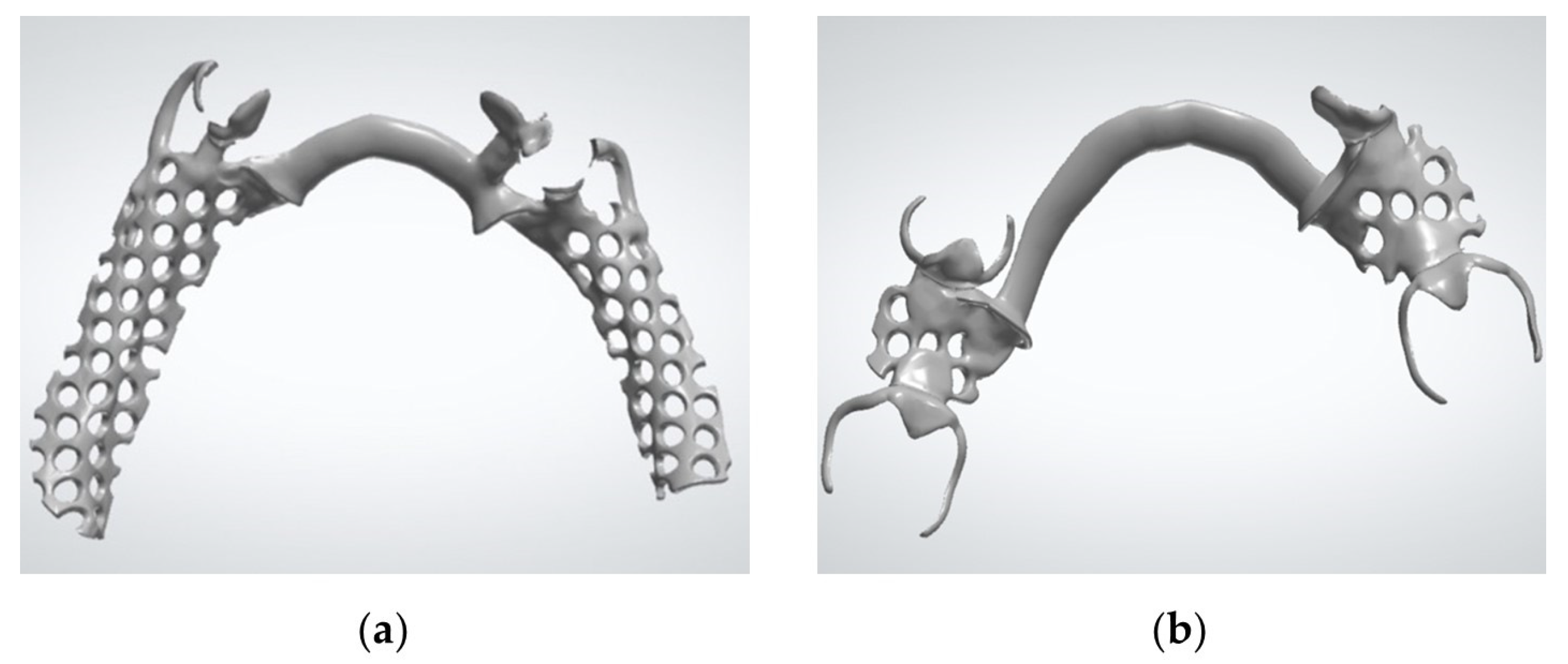
The prepared models were scanned with a laboratory scanner (Medit T500, Medit®, Seoul, Republic of Korea), and the PartialCAD software basic version (Partial Planner, Zirkonzahn®, Gais, Italy) was used to analyze the insertion axis, eliminate the unwanted undercuts, and create the digital design of the frameworks (Figure 2). The STL files were saved and exported to the CAM equipment to begin the manufacturing process.
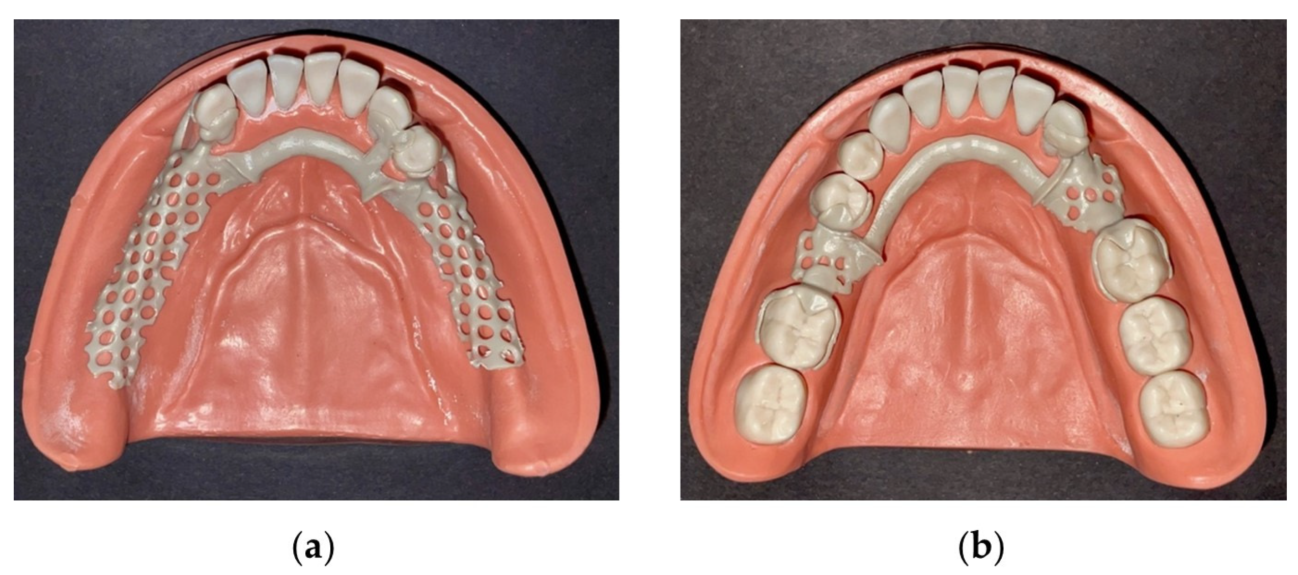
For each study model, two frameworks were produced with CAD-CAM: (i) one in Co-Cr (Figure 3), using a Co-Cr alloy and an SLM machine (EOS GmbH, Phibo®, Barcelona, Spain), followed by a heat treatment to improve the mechanical properties; and (ii) the other in PEEK (Figure 4), by direct milling (M5, Zirkonzahn®, Gais, Italy) of a PEEK disc (Zirkonzahn Tecno Med 95H20; Ref.: TMAH0120—Lot.: 15922). The Co-Cr frameworks were finished with drills and rubbers, immersed in an electrolyte bath, and polished with brushes and paste. The PEEK frameworks were finished using drills to remove the supports and then submitted to rubber polishing.
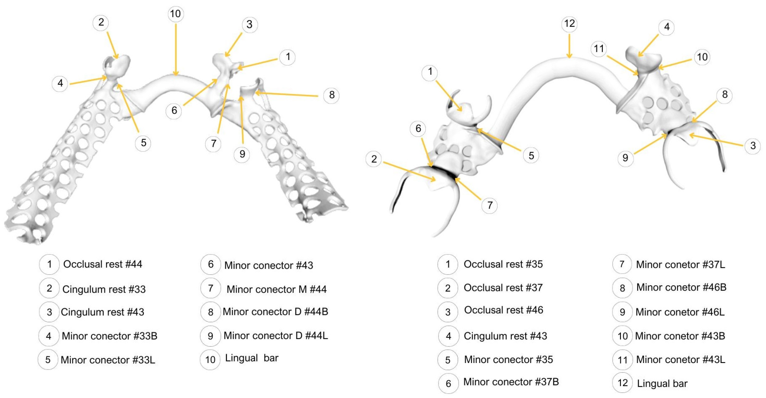
Each framework was correctly placed on the corresponding study model, and a qualitative fit accuracy assessment method was applied. The method was based on a direct inspection of the gap between the framework components and the model surface, using image amplification and calibrated endodontic instruments that explore the entire peripheral area of the component. The framework components used as measuring sites are illustrated in Figure 5.
The fit assessment of the major connector was performed using a Kerr file size 50, whose tip has a 500 μm diameter. An endodontic plugger size 35, with a tip diameter of 350 μm, was used to assess the remaining framework components (cingular and occlusal rests and minor connectors). Misfitting was considered in the presence of a gap equal to or higher than 500 μm or 350 μm, respectively.
To complement this analysis, whenever a misfit higher than the tip diameter of the instrument was identified, a Williams periodontal probe was used to confirm whether the gap was equal to or higher than 1000 μm.
Two types of image amplification were used for all measurements—magnifying loupes (1.8×) (Lorben 1.8× head magnifier) and a stereoscopic microscope (20×) (Olympus SZ-ET, Olympus®, Tokyo, Japan).
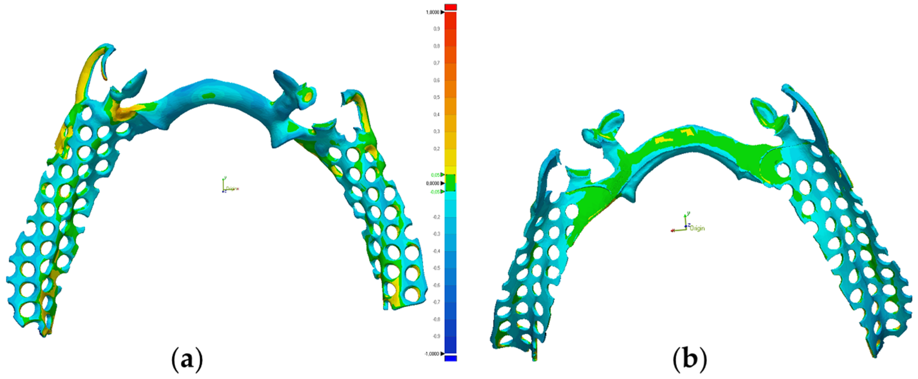
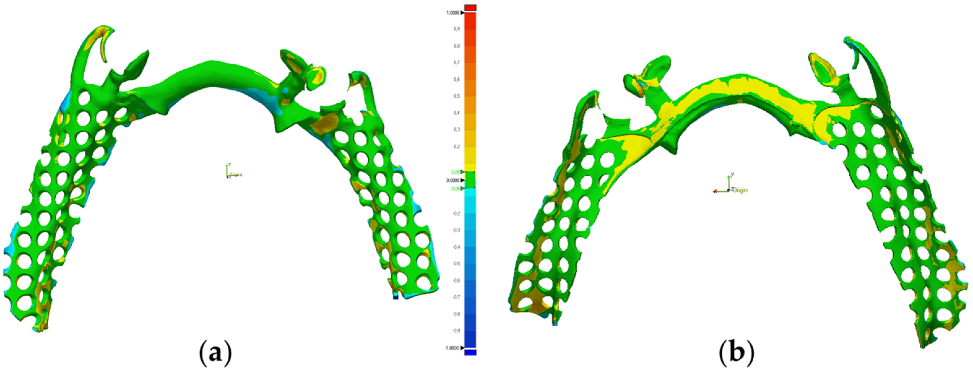
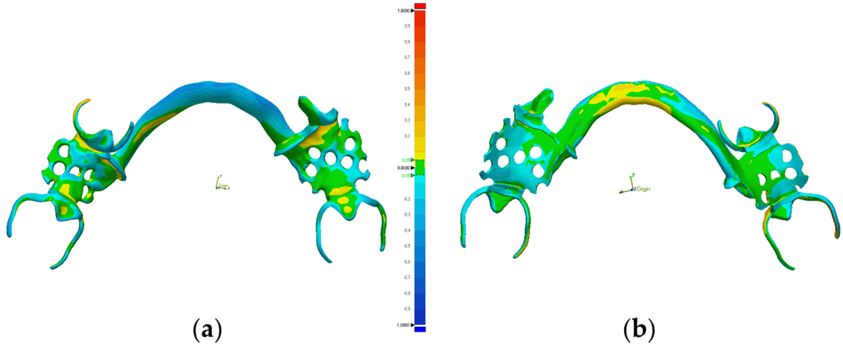
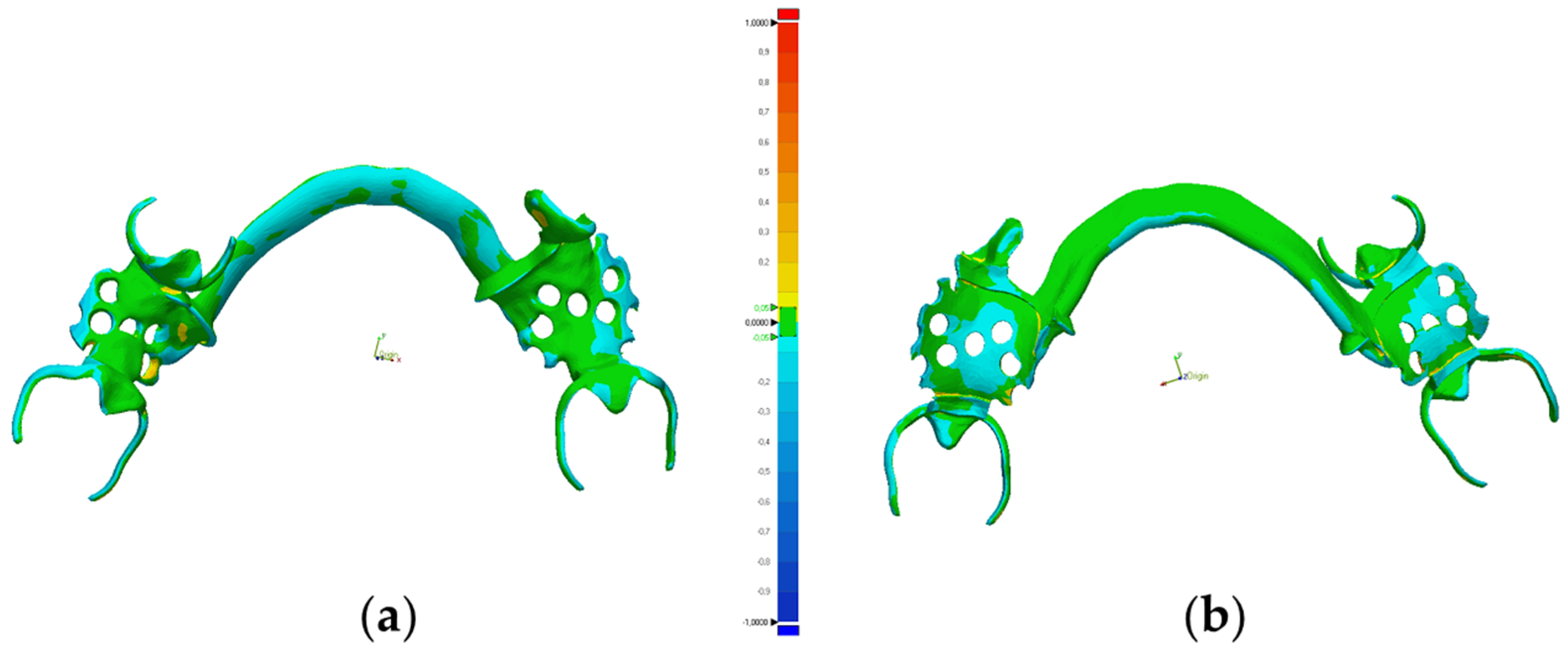
A digital quantitative assessment of trueness through putative discrepancies between the manufactured frameworks and the original standard tessellation language (STL) files was carried out using the Geomagic software (Geomagic Control X version 2018, 3D Systems Inc., USA). For that purpose, the PEEK and Co-Cr frameworks were scanned using the S600 Arti laboratory scanner (S600 Arti, Zirkonzahn, Gais, Italy) in order to obtain the polygonal mesh of the produced frameworks in STL files (CAD framework produced, CFP). The trueness of the prosthetic frameworks was then assessed by digitally superimposing the CFP onto the STL file of the original CAD design (CAD framework designed, CFD). A tolerance level of ±50 μm was set in the Geomagic software. Color maps were used for easier visualization of discrepancies between CFP and CFD, with green areas representing good matching between the CFP and the CFD, blue areas corresponding to negative deviations (CFP smaller than the CFD) and red areas illustrating positive deviations (CFP larger than the CFD). Quantitative dimensional differences between CFP and CFD, measured in micrometers, were calculated using root mean square (RMS), mean and standard deviation values.

3. Results

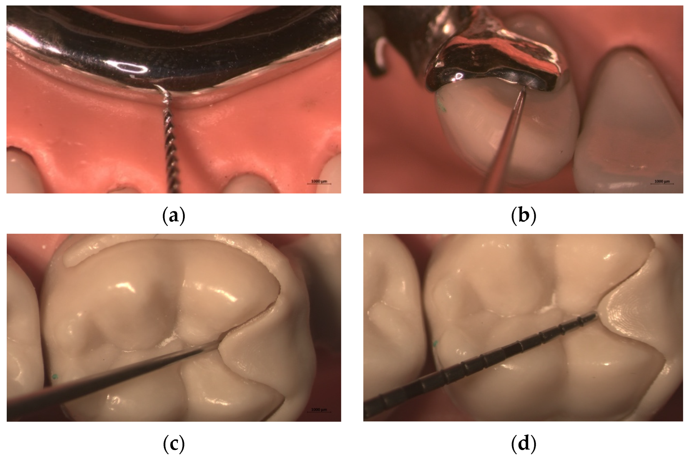
Data collected through the qualitative fit accuracy assessment are summarized in Table 1, Table 2, Table 3 and Table 4. Examples of adapted (A) and misfit (MF) points found during the qualitative assessment are depicted in Figure 6.
In Kennedy’s Class I (Table 1), the Co-Cr framework showed a misfit in one out of ten evaluated sites, with both magnifying loupes (MLs) and stereoscopic microscope (SM). On the other hand, in the PEEK framework, all the assessed points were adapted, with both image amplification methods. In Kennedy’s Class III modification 1 (Table 2), the Co-Cr framework showed a misfit in four out of twelve points assessed, whereas the PEEK framework presented a misfit in three points, with both amplification methods.
The misfitting sites identified with the endodontic instruments were checked with a Williams periodontal probe and all were lower than 1000 μm, which was confirmed in both the amplification methods used (Table 3 and Table 4).
Visual inspection of the color maps obtained after digital superimpositions finds that the milled PEEK frameworks exhibited more green areas than the SLM-printed Co-Cr frameworks, particularly evident in Kennedy’s Class I (Figure 7, Figure 8, Figure 9 and Figure 10).
RMS values were calculated as a quantitative measure of the trueness. Lower RMS values correspond to higher trueness. Accordingly, in Kennedy’s Class I (Table 5), the trueness was higher in the PEEK framework than in the Co-Cr one (RMS = 69.2 μm vs. RMS = 148.3 μm, respectively). Similar results were observed in Kennedy’s Class III modification 1 (Table 6), with PEEK providing the best trueness (RMS = 59.7 μm vs. RMS = 107.2 μm).

4. Discussion

In this in vitro pilot study, the PEEK frameworks obtained by milling showed a better fit accuracy to the corresponding models than the SLM-printed Co-Cr frameworks in both Kennedy classes, with the PEEK framework of a mandibular Kennedy Class I presenting the best scores.
RPD manufacturing through CAD/CAM technologies has emerged as a promising strategy. Since it may involve either subtractive or additive methods that can be combined with a variety of materials, a thorough evaluation of the frameworks produced by CAD/CAM is still limited and sometimes inconsistent, demanding further research [11,12,16].
To the best of our knowledge, no available studies compare milled PEEK with SLM-printed Co-Cr frameworks. Nevertheless, several studies have addressed these materials and manufacturing techniques separately. Consistent with our data, Ye et al. observed a better fit accuracy of milled PEEK frameworks compared with Co-Cr frameworks produced using a conventional method, with PEEK showing clinically acceptable gaps for occlusal rests (86.2 ± 22.6 μm) and major connectors (52.8 ± 44.6 μm) [37]. According to Negm et al., PEEK frameworks manufactured by milling also showed clinically acceptable values (<311 μm) at the rests (70 ± 90 μm) and major connectors [21]. In turn, Soltanzadeh et al., assessing Co-Cr frameworks fabricated using different techniques, observed that the SLM-printed Co-Cr frameworks presented the poorest fitting when compared with Co-Cr frameworks produced with (i) the lost-wax technique from a stone model, (ii) 3D printing from a stone model and (iii) the lost-wax technique from a resin model [7]. When the fit accuracy of PEEK frameworks to oral structures was subjectively rated, adequate fitting scores were reported [23]. Also, patients showed higher satisfaction compared to the use of Co-Cr RPDs [38]. Although this evidence provides essential clues, the diversity of the assessment methods and manufacturing techniques preclude a direct comparison with our results.
From a clinical perspective, the gap between the inner surface of the framework and the supporting structures represents the fit accuracy of an RPD [29]. Various methods for assessing this gap have been described in the literature [7,39], but a gold-standard method is still unreported. The fitting of an RPD framework can be analyzed either qualitatively or quantitatively [31]. As they are simple and fast, qualitative assessment methods, such as visual inspection or pressing tests, are widely used, but the information collected needs to be more precise and objective [31]. In quantitative assessment methods, a direct measure of the gap using analog instruments has proven difficult, as it involves sectioning the RPD, which may not reflect the overall fitting [7]. Therefore, an indirect quantitative assessment of the gap has often been applied through a silicone mold of this discrepancy, followed by the measurement of its weight or thickness [3,31,39,40]. However, the deformation and rupture of the elastomeric material during its manipulation, coupled with the difficulty of measuring its thickness due to its elasticity, are important disadvantages of this approach [15,29,40].
The current study used a qualitative analog method based on direct inspection of the gap between the framework components and the model surface, using image amplification and calibrated endodontic instruments (endodontic plugger #35 and file #50). A qualitative assessment using calibrated endodontic instruments was previously described by Conceição et al. [33]. A similar method based on using a calibrated orthodontic wire of 500 μm has already been described by other authors [32]. The choice of calibrated instruments was supported by previous research by Eggbeer et al. [30], who classified a gap between 0 and 50 μm as intimate contact between the structures, and a space ranging from 50 to 311 μm as clinically acceptable [7,30]. In line with this information, an endodontic plugger with a tip diameter of 350 μm was used to assess the occlusal and cingular rests, and minor connectors, while an endodontic file #50 (tip diameter of 500 μm) was used to assess the major connectors, for which a relief of 400 μm was automatically established by the CAD software.
Image amplification coupled with the calibrated endodontic instruments was a strategy to provide more accurate and reliable assessment than simple visual inspection. Interestingly, the results obtained with the two image magnification modalities—magnifying loupes and a stereoscopic microscope—were coincident in all the sites assessed, suggesting that magnifying loupes, often used in daily clinical practice, allow the identification of the same misfits as more expensive equipment.
In contrast with other authors who restricted the points evaluated to the RPD rests [11,31,35], our qualitative assessment involved almost all the RPD components (occlusal and cingular rests, minor and major connectors) as an attempt to gain further insight into the overall fitting of the framework. Although this analog method only identifies gaps at the periphery of a specific component, not considering the intaglio surface, it enables a feasible, simple and low-cost fit assessment of a framework, which may be routinely carried out in clinical or laboratory (quality control) contexts.
The ability of a technique to result in the manufacture of objects with minimal differences from the original design represents the trueness [34]. Discrepancies between the structure produced and the original digital design can result in gaps between the prosthetic framework and the supporting structures, or excess material. Both situations may compromise the fitting and clinical success of the RPD.
It is important to clarify that accuracy consists of trueness (proximity of measurement results to the true value) and precision (repeatability or reproducibility) [41]. Through visual analysis of the color mapping generated by Geomagic superimpositions, it is possible to determine the direction of the displacement and understand the type of distortion observed [42]. In the current study, it was evident that the PEEK frameworks exhibited more green areas (high trueness) and increased color uniformity than the Co-Cr ones for both Kennedy classes, but especially in the Class I edentulous condition.
Digital superimposition also enabled a quantitative assessment of the trueness. This study defined trueness as the discrepancy between the frameworks produced and the original CAD design, which was expressed as RMS. This value indicates how far the discrepancies between the files are from zero, with a value of zero indicating a perfect match between the files. Thus, a high correspondence between the superimposed files depicts high trueness and occurs when low RMS values are recorded [42,43,44]. Analyzing the RMS values obtained, it was possible to conclude that the discrepancies between the produced frameworks and the original CAD design were lower in the PEEK than in the Co-Cr frameworks, in both Kennedy Classes, indicating a higher trueness of the milled PEEK frameworks. Although a complete correlation cannot be established due to diverse experimental conditions and specimens, these results are in agreement with those obtained by Arnold et al., who concluded that PEEK frameworks produced by milling (43 ± 23 μm horizontal and 38 ± 21 μm vertical) showed lower distortion and increased precision in comparison with frameworks fabricated with SLM (365 ± 205 μm horizontal and 363 ± 133 μm vertical) [11]. Negm et al. also found that PEEK frameworks produced directly by milling exhibited low discrepancies (17.36 ± 4.32 μm) and uniform color maps [18]. In addition, evaluating metal frameworks produced indirectly by milling and additive techniques, Snosi et al. found that subtractive techniques displayed fewer deviations and therefore greater trueness (150.1 ± 20.5 μm) than additive techniques (179.0 ± 13.7 μm) [39]. Other work conducted by Peng et al. reported that RPD frameworks fabricated with SLM had a better trueness (RMS = 350 μm) than frameworks produced using the conventional method [2]. In that study, the discrepancy levels were higher than those obtained in the current investigation for SLM-printed Co-Cr frameworks (−73.3 ± 28.9 μm for Class I and −33.3 ± 101.9 μm for Class III, modification 1).
Although relevant insights have been provided, our study has some limitations that should be mentioned. They are related to the accuracy of the laboratory scanners used for image acquisition and the difficulties found during the scanning of the external and internal surfaces of the produced frameworks to capture all points of interest. The precision level achieved by the manufacturing equipment and the settings used in the CAM machine may have also influenced our results. The finishing and polishing procedures may have had an impact on the final quality of the frameworks that should not be neglected. Furthermore, since our work involved two materials and two production techniques, isolated comparisons regarding either the material or the manufacturing method per se cannot be established. The decision of using 3D printing for Co-Cr manufacturing instead of a milling technique was supported by the high costs and rapid wear of cutting tools observed in the latter, which impair its routine use in clinical practice. As this was a pilot study, the reduced number of models and frameworks assessed constitutes a bias of the current work, precluding any conclusions regarding the reproducibility of the manufacturing systems used. Finally, the absence of a control group, which may include RPD frameworks produced by the corresponding conventional methods, is a drawback of this study. In future research, besides increasing the sample size, a digital fit accuracy assessment method should be considered in order to enable a more objective and straight forward analysis. Apart from improving the in vitro data collection, clinical research is mandatory to evaluate the oral performance of these RPD frameworks, focused on the effects on both supporting tissues and patients’ comfort/satisfaction levels.

5. Conclusions

Considering the results presented, this pilot study reveals that the milled PEEK frameworks showed a better fit accuracy and trueness than the SLM-printed Co-Cr frameworks, in both Kennedy classes addressed.
Although valuable, this data deserves validation by further in vitro studies with larger samples, which should include other Kennedy classes, models and an increased number of frameworks assessed. Complementary in vivo research is also crucial to fully understand the clinical performance of these RPD frameworks.

Author Contributions

Conceptualization, M.M.S.-F. and M.H.F.; methodology, L.B., S.J.O. and M.A.S.-F.; software, R.M.; investigation, L.B. and M.M.S.-F.; resources, C.B.N. and R.M.; writing—original draft preparation, L.B. and M.A.S.-F.; writing—review and editing, C.B.N. and S.J.O.; supervision, M.H.F. and M.M.S.-F. All authors have read and agreed to the published version of the manuscript.

Funding

This research received no external funding.

Institutional Review Board Statement

Not applicable.

Informed Consent Statement

Not applicable.

Data Availability Statement

Data are available upon reasonable request to the corresponding authors. The data are not publicly available due to privacy.

Conflicts of Interest

The authors declare no conflict of interest.

References

  1. Lee, W.T.; Chen, Y.C. Digitally Fabricated Dentures for Full Mouth Rehabilitation with Zirconia, Polyetheretherketone and Selective Laser Melted Ti-6Al-4V Material. Int. J. Environ. Res. Public Health 2022, 19, 3021. [Google Scholar] [CrossRef] [PubMed]
  2. Peng, P.W.; Hsu, C.Y.; Huang, H.Y.; Chao, J.C.; Lee, W.F. Trueness of removable partial denture frameworks additively manufactured with selective laser melting. J. Prosthet. Dent. 2022, 127, 122–127. [Google Scholar] [CrossRef] [PubMed]
  3. Bajunaid, S.O.; Altwaim, B.; Alhassan, M.; Alammari, R. The Fit Accuracy of Removable Partial Denture Metal Frameworks Using Conventional and 3D Printed Techniques: An In Vitro Study. J. Contemp. Dent. Pract. 2019, 20, 476–481. [Google Scholar] [CrossRef] [PubMed]
  4. Almufleh, B.; Emami, E.; Alageel, O.; de Melo, F.; Seng, F.; Caron, E.; Nader, S.A.; Al-Hashedi, A.; Albuquerque, R.; Feine, J.; et al. Patient satisfaction with laser-sintered removable partial dentures: A crossover pilot clinical trial. J. Prosthet. Dent. 2018, 119, 560–567. [Google Scholar] [CrossRef] [PubMed]
  5. Tregerman, I.; Renne, W.; Kelly, A.; Wilson, D. Evaluation of removable partial denture frameworks fabricated using 3 different techniques. J. Prosthet. Dent. 2019, 122, 390–395. [Google Scholar] [CrossRef] [PubMed]
  6. Kim, J.J. Revisiting the Removable Partial Denture. Dent. Clin. N. Am. 2019, 63, 263–278. [Google Scholar] [CrossRef] [PubMed]
  7. Soltanzadeh, P.; Suprono, M.S.; Kattadiyil, M.T.; Goodacre, C.; Gregorius, W. An In Vitro Investigation of Accuracy and Fit of Conventional and CAD/CAM Removable Partial Denture Frameworks. J. Prosthodont. 2019, 28, 547–555. [Google Scholar] [CrossRef]
  8. Schweiger, J.; Güth, J.F.; Erdelt, K.J.; Edelhoff, D.; Schubert, O. Internal porosities, retentive force, and survival of cobalt-chromium alloy clasps fabricated by selective laser-sintering. J. Prosthodont. Res. 2020, 64, 210–216. [Google Scholar] [CrossRef]
  9. Anes, V.; Neves, C.B.; Bostan, V.; Gonçalves, S.; Reis, L. Evaluation of the retentive forces from removable partial denture clasps manufactured by the digital method. Appl. Sci. 2023, 13, 8072. [Google Scholar] [CrossRef]
  10. Lee, S.J.; Kim, S.W.; Lee, J.J.; Cheong, C.W. Comparison of Intraoral and Extraoral Digital Scanners: Evaluation of Surface Topography and Precision. Dent. J. 2020, 8, 52. [Google Scholar] [CrossRef]
  11. Arnold, C.; Hey, J.; Schweyen, R.; Setz, J.M. Accuracy of CAD-CAM-fabricated removable partial dentures. J. Prosthet. Dent. 2018, 119, 586–592. [Google Scholar] [CrossRef] [PubMed]
  12. Barraclough, O.; Gray, D.; Ali, Z.; Nattress, B. Modern partial dentures—Part 1: Novel manufacturing techniques. Br. Dent. J. 2021, 230, 651–657. [Google Scholar] [CrossRef] [PubMed]
  13. Rokaya, D.; Bohara, S.; Srimaneepong, V.; Kongkiatkamon, S.; Khurshid, Z.; Heboyan, A.; Zafar, M.S.; Sapkota, J. Metallic Biomaterials for Medical and Dental Prosthetic Applications. In Functional Biomaterials; Jana, S., Jana, S., Eds.; Springer: Singapore, 2022; pp. 503–522. [Google Scholar]
  14. Cevik, P.; Schimmel, M.; Yilmaz, B. New generation CAD-CAM materials for implant-supported definitive frameworks fabricated by using subtractive technologies. BioMed Res. Int. 2022, 2022, 3074182. [Google Scholar] [CrossRef] [PubMed]
  15. Tasaka, A.; Shimizu, T.; Kato, Y.; Okano, H.; Ida, Y.; Yamashita, S. Accuracy of removable partial denture framework fabricated by casting with a 3D printed pattern and selective laser sintering. J. Prosthodont. Res. 2020, 64, 224–230. [Google Scholar] [CrossRef] [PubMed]
  16. Conceição, P.; Portugal, J.; Neves, C.B. Evaluation of Removable Partial Denture Metal Frameworks Produced by Digital Methods—A Systematic Review. Appl. Sci. 2023, 13, 10824. [Google Scholar] [CrossRef]
  17. Alabdullah, S.A.; Hannam, A.G.; Wyatt, C.C.; McCullagh, A.P.G.; Aleksejuniene, J.; Mostafa, N.Z. Comparison of digital and conventional methods of fit evaluation of partial removable dental prosthesis frameworks fabricated by selective laser melting. J. Prosthet. Dent. 2022, 127, 478.e1–478.e10. [Google Scholar] [CrossRef] [PubMed]
  18. Lee, W.F.; Wang, J.C.; Hsu, C.Y.; Peng, P.W. Microstructure, mechanical properties, and retentive forces of cobalt-chromium removable partial denture frameworks fabricated by selective laser melting followed by heat treatment. J. Prosthet. Dent. 2022, 127, 115–121. [Google Scholar] [CrossRef] [PubMed]
  19. Dikova, T. Chapter 5: Properties of Co-Cr Dental Alloys Fabricated Using Additive Technologies. In Biomaterials in Regenerative Medicine; Dobrzański, L.A., Ed.; InTechOpen: London, UK, 2018; pp. 141–159. [Google Scholar]
  20. Campbell, S.D.; Cooper, L.; Craddock, H.; Hyde, T.P.; Nattress, B.; Pavitt, S.H.; Seymour, D.W. Removable partial dentures: The clinical need for innovation. J. Prosthet. Dent. 2017, 118, 273–280. [Google Scholar] [CrossRef]
  21. Negm, E.E.; Aboutaleb, F.A.; Alam-Eldein, A.M. Virtual Evaluation of the Accuracy of Fit and Trueness in Maxillary Poly(etheretherketone) Removable Partial Denture Frameworks Fabricated by Direct and Indirect CAD/CAM Techniques. J. Prosthodont. 2019, 28, 804–810. [Google Scholar] [CrossRef]
  22. Gentz, F.I.; Brooks, D.I.; Liacouras, P.C.; Petrich, A.; Hamlin, C.M.; Ellert, D.O.; Ye, L. Retentive Forces of Removable Partial Denture Clasp Assemblies Made from Polyaryletherketone and Cobalt-Chromium: A Comparative Study. J. Prosthodont. 2022, 31, 299–304. [Google Scholar] [CrossRef]
  23. Harb, I.E.; Abdel-Khalek, E.A.; Hegazy, S.A. CAD/CAM Constructed Poly(etheretherketone) (PEEK) Framework of Kennedy Class I Removable Partial Denture: A Clinical Report. J. Prosthodont. 2019, 28, e595–e598. [Google Scholar] [CrossRef] [PubMed]
  24. Mayinger, F.; Micovic, D.; Schleich, A.; Roos, M.; Eichberger, M.; Stawarczyk, B. Retention force of polyetheretherketone and cobalt-chrome-molybdenum removable dental prosthesis clasps after artificial aging. Clin. Oral Investig. 2021, 25, 3141–3149. [Google Scholar] [CrossRef] [PubMed]
  25. Zoidis, P.; Papathanasiou, I.; Polyzois, G. The Use of a Modified Poly-Ether-Ether-Ketone (PEEK) as an Alternative Framework Material for Removable Dental Prostheses. A Clinical Report. J. Prosthodont. 2016, 25, 580–584. [Google Scholar] [CrossRef] [PubMed]
  26. Vaicelyte, A.; Janssen, C.; Le Borgne, M.; Grosgogeat, B. Cobalt–Chromium Dental Alloys: Metal Exposures, Toxicological Risks, CMR Classification, and EU Regulatory Framework. Crystals 2020, 10, 1151. [Google Scholar] [CrossRef]
  27. Suphangul, S.; Rokaya, D.; Kanchanasobhana, C.; Rungsiyakull, P.; Chaijareenont, P. PEEK Biomaterial in Long-Term Provisional Implant Restorations: A Review. J. Funct. Biomater. 2022, 13, 33. [Google Scholar] [CrossRef] [PubMed]
  28. Al-Haj Husain, N.; Özcan, M.; Schimmel, M.; Abou-Ayash, S. A digital cast-free clinical workflow for oral rehabilitation with removable partial dentures: A dental technique. J. Prosthet. Dent. 2020, 123, 680–685. [Google Scholar] [CrossRef]
  29. Oh, K.C.; Yun, B.S.; Kim, J.H. Accuracy of metal 3D printed frameworks for removable partial dentures evaluated by digital superimposition. Dent. Mater. 2022, 38, 309–317. [Google Scholar] [CrossRef]
  30. Eggbeer, D.; Bibb, R.; Williams, R. The computer-aided design and rapid prototyping fabrication of removable partial denture frameworks. Proc. Inst. Mech. Eng. Part H 2005, 219, 195–202. [Google Scholar] [CrossRef]
  31. Ye, H.; Ning, J.; Li, M.; Niu, L.; Yang, J.; Sun, Y.; Zhou, Y. Preliminary Clinical Application of Removable Partial Denture Frameworks Fabricated Using Computer-Aided Design and Rapid Prototyping Techniques. Int. J. Prosthodont. 2017, 30, 348–353. [Google Scholar] [CrossRef]
  32. Keltjens, H.M.; Mulder, J.; Käyser, A.F.; Creugers, N.H. Fit of direct retainers in 9 partial dentures after 8 years of use. J. Oral Rehabil. 1997, 24, 138–142. [Google Scholar] [CrossRef]
  33. Saad, A.; Abbas, F.; Elgharabawy, S. Clinical evaluation of removable partial denture constructed from 3d printed resin pattern designed using CAD CAM technology. Alex. Dent. J. 2019, 44, 15–21. [Google Scholar] [CrossRef]
  34. Tasaka, A.; Okano, H.; Shimizu, T.; Kato, Y.; Higuchi, S.; Yamashita, S. Influence of reinforcement bar on accuracy of removable partial denture framework fabricated by casting with a 3D-printed pattern and selective laser sintering. J. Prosthodont. Res. 2021, 65, 213–218. [Google Scholar] [CrossRef] [PubMed]
  35. Conceição, P.; Franco, M.; Alves, N.; Portugal, J.; Neves, C.B. Fit accuracy of removable partial denture metal frameworks produced by CAD-CAM—A clinical study. Rev. Port. Estomatol. Med. Dent. Cir. Maxilofac. 2021, 62, 194–200. [Google Scholar] [CrossRef]
  36. Guo, F.; Huang, S.; Liu, N.; Hu, M.; Shi, C.; Li, D.; Liu, C. Evaluation of the mechanical properties and fit of 3D-printed polyetheretherketone removable partial dentures. Dent. Mater. J. 2022, 41, 816–823. [Google Scholar] [CrossRef]
  37. Ye, H.; Li, X.; Wang, G.; Kang, J.; Liu, Y.; Sun, Y.; Zhou, Y. A Novel Computer-Aided Design/Computer- Assisted Manufacture Method for One-Piece Removable Partial Denture and Evaluation of Fit. Int. J. Prosthodont. 2018, 31, 149–151. [Google Scholar] [CrossRef]
  38. Mohamed, S.; Rasha, H. Digital PEEK framework and patient satisfaction compared to conventional metal framework in removable partial dentures. A clinical trial. Egypt. Dent. J. 2019, 65, 3787–3794. [Google Scholar] [CrossRef]
  39. Conceição, P.; Portugal, J.; Franco, M.; Alves, N.M.; Marques, D.; Neves, C.B. Comparison between digital superimposition and microcomputed tomography methods of fit assessment of removable partial denture frameworks. J. Prosthet. Dent. 2023, in press. [Google Scholar] [CrossRef]
  40. Lee, J.W.; Park, J.M.; Park, E.J.; Heo, S.J.; Koak, J.Y.; Kim, S.K. Accuracy of a digital removable partial denture fabricated by casting a rapid prototyped pattern: A clinical study. J. Prosthet. Dent. 2017, 118, 468–474. [Google Scholar] [CrossRef]
  41. ISO 5725-1:2023; Accuracy (Trueness and Precision) of Measurement Methods and Results—Part 1: General Principles and Definitions. International Standard Organization: Geneva, Switzerland, 2023.
  42. Sampaio-Fernandes, M.A.; Pinto, R.; Sampaio-Fernandes, M.M.; Sampaio-Fernandes, J.C.; Marques, D.; Figueiral, M.H. Accuracy of silicone impressions and stone models using two laboratory scanners: A 3D evaluation. Int. J. Prosthodont. 2022. ahead of print. [Google Scholar] [CrossRef]
  43. Snosi, A.M.; Lotfy, S.M.; Thabet, Y.G.; Sabet, M.E.; Rizk, F.N. Subtractive versus additive indirect manufacturing techniques of digitally designed partial dentures. J. Adv. Prosthodont. 2021, 13, 327–332. [Google Scholar] [CrossRef]
  44. Yilmaz, B.; Marques, V.R.; Donmez, M.B.; Cuellar, A.R.; Lu, W.E.; Abou-Ayash, S.; Çakmak, G. Influence of 3D analysis software on measured deviations of CAD-CAM resin crowns from virtual design file: An in-vitro study. J. Dent. 2022, 118, 103933. [Google Scholar] [CrossRef] [PubMed]
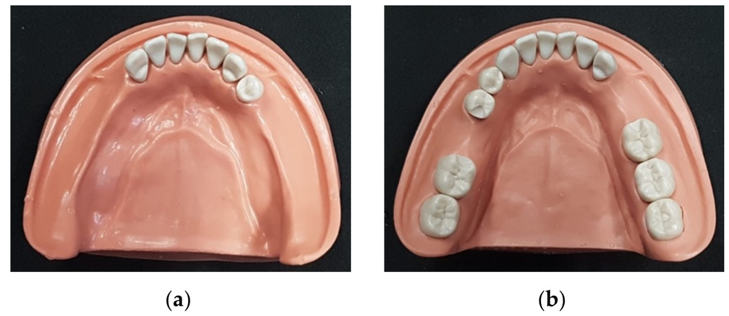
Figure 1. Mandibular study models with rest seat preparations: (a) Kennedy Class I; (b) Kennedy Class III, modification 1.
Applsci 14 00118 g001
Figure 2. CAD design of the prosthetic frameworks: (a) Kennedy Class I framework design; (b) Kennedy Class III, modification 1, framework design.
Applsci 14 00118 g002
Figure 3. SLM-printed Co-Cr frameworks: (a) Kennedy Class I; (b) Kennedy Class III, modification 1.
Applsci 14 00118 g003
Figure 4. Milled PEEK frameworks: (a) Kennedy Class I; (b) Kennedy Class III, modification 1.
Applsci 14 00118 g004
Figure 5. Evaluated sites on the qualitative assessment of fit accuracy for each Kennedy class. B—buccal; L—lingual; M—mesial; D—distal.
Applsci 14 00118 g005
Figure 6. Illustrative images of the qualitative assessment of fit accuracy of the frameworks, showing adapted (A) and misfit (MF) points: (a) Co-Cr framework adapted at lingual bar (endodontic file); (b) Co-Cr framework adapted at cingular rest (endodontic plug); (c) PEEK framework misfit at occlusal rest ˃350 μm (endodontic plug); (d) PEEK framework misfit at occlusal rest ˂1000 μm (periodontal probe).
Applsci 14 00118 g006
Figure 7. Co-Cr frameworks (Kennedy class I)—color maps of the discrepancies between CFP and CFD: (a) external surface; (b) internal surface.
Applsci 14 00118 g007
Figure 8. PEEK frameworks (Kennedy class I)—color maps of the discrepancies between CFP and CFD: (a) external surface; (b) internal surface.
Applsci 14 00118 g008
Figure 9. Co-Cr frameworks (Kennedy class III, modification 1)—color maps of the discrepancies between CFP and CFD: (a) external surface; (b) internal surface.
Applsci 14 00118 g009
Figure 10. PEEK frameworks (Kennedy class III, modification 1)—color maps of the discrepancies between CFP and CFD: (a) external surface; (b) internal surface.
Applsci 14 00118 g010
Table 1. Qualitative assessment of fit accuracy for Kennedy’s Class I frameworks (with image amplification and calibrated endodontic instruments).
Kennedy Class ICo-Cr FrameworkPEEK Framework
LoupesMicroscopeLoupesMicroscope
Occlusal rest #44AAAA
Cingulum rest #33AAAA
Cingulum rest #43AAAA
Minor connector #33BMFMFAA
Minor connector #33LAAAA
Minor connector #43AAAA
Minor connector M #44AAAA
Minor connector D #44BAAAA
Minor connector D #44LAAAA
Lingual barAAAA
A—adapted (no gap with endodontic instruments); MF—misfit ≥ 350 μm. B—buccal; L—lingual; M—mesial; D—distal.
Table 2. Qualitative results of clinical inspection method with image amplification and calibrated endodontic instruments for Kennedy Class III, modification 1.
Kennedy Class III,
Modification 1
Co-Cr FrameworkPEEK Framework
LoupesMicroscopeLoupesMicroscope
Occlusal rest #35AAAA
Occlusal rest #37MFMFAA
Occlusal rest #46MFMFMFMF
Occlusal rest #43AAAA
Minor connector #35AAAA
Minor connector #37BAAAA
Minor connector #37LMFMFMFMF
Minor connector #46BMFMFMFMF
Minor connector #46LAAAA
Minor connector #43BAAAA
Minor connector #43LAAAA
Lingual barAAAA
A—adapted (no gap with endodontic instruments); MF—misfit ≥ 350 μm. B—buccal; L—lingual; M—mesial; D—distal.
Table 3. Qualitative assessment of misfit components for Kennedy’s Class I frameworks (with image amplification and Williams periodontal probe).
Kennedy Class ICo-Cr Framework
LoupesMicroscope
Minor connector #33BMF′MF′
A—adapted; MF′—misfit ˂ 1000 μm; B—buccal.
Table 4. Qualitative results of clinical inspection method with image amplification and a periodontal Williams probe for Kennedy Class III, modification 1.
Kennedy Class III,
Modification 1
Co-Cr FrameworkPEEK Framework
LoupesMicroscopeLoupesMicroscope
Occlusal rest #37MF′MF′--
Occlusal rest #46MF′MF′MF′MF′
Minor connector #37LMF′MF′MF′MF′
Minor connector #46BMF′MF′MF′MF′
A—adapted; MF′—misfit ˂ 1000 μm; B—buccal; L—lingual.
Table 5. Quantitative assessment of trueness (expressed in μm) for Kennedy’s Class I frameworks.
Co-Cr FrameworkPEEK Framework
Maximum594.5430.1
Minimum−594.8−430.1
Mean−73.325.4
Standard Deviation 128.964.4
Root Mean Square (RMS)148.369.2
Table 6. Quantitative assessment of trueness (expressed in μm) for Kennedy’s Class III modification 1 frameworks.
Co-Cr FrameworkPEEK Framework
Maximum454.4302.1
Minimum−455.4−300.9
Mean−33.3−26.9
Standard Deviation 101.953.2
Root Mean Square (RMS)107.259.7
Disclaimer/Publisher’s Note: The statements, opinions and data contained in all publications are solely those of the individual author(s) and contributor(s) and not of MDPI and/or the editor(s). MDPI and/or the editor(s) disclaim responsibility for any injury to people or property resulting from any ideas, methods, instructions or products referred to in the content.