Article

Water Heating and Circulating Heating System with Energy-Saving Optimization Control

1
Graduate Institute of Automation Technology, National Taipei University of Technology, Taipei 10608, Taiwan
2
Smart Automation Unit, TECO Electric & Machinery Co., Ltd., 10F, No. 3-1, Park St., Nan-Kang, Taipei 11503, Taiwan
*
Author to whom correspondence should be addressed.
Appl. Sci. 2023, 13(9), 5542; https://doi.org/10.3390/app13095542
Submission received: 29 March 2023 / Revised: 24 April 2023 / Accepted: 26 April 2023 / Published: 29 April 2023
(This article belongs to the Special Issue Fluid Flow and Heat Transfer: Latest Advances and Prospects)

Abstract

:
Over the past few years, due to an aging population and a longer life expectancy, traditional high-oil, high-calorie, and high-temperature culinary concepts have been widely replaced by healthier, low-temperature heating methods. However, while the key device of the Sous-Vide heating system ordinarily operates at full power to achieve the target temperature, pump speed control is not currently considered within the water heating and circulating system framework. This study develops a model for a water heating and circulating system and examines the characteristics of the lowest power point and pump speed. Building upon these results, we present the LPPT control method as a means of optimizing input power for heating. The effectiveness of this method is supported by simulations and experiments, which demonstrate a significant reduction in energy consumption. The control concept calculates the real-time input power based on the input voltage and current, and it can achieve the most efficient input power by perturbing the pump speed. It is demonstrated that applying LPPT to daily pot capacity reduces the Sous-Vide Cooker’s input power by up to 17% and achieves efficiency optimization control by removing the need to calculate the foods and other parameters of the water heating and circulating system environment.

1. Introduction

With an aging population and a longer life expectancy, since the early 1990s, heating methods have slowly shifted away from high-oil and high-calorie heating to healthful, organic processes [1,2]. In contrast to traditional high-temperature heating methods such as sauteing, stir-frying, deep-frying, and boiling, this method cooks ingredients in water at a low temperature, and it is known as the water heating and circulating method [3]. Recently, the water heating and circulating method has gained popularity and gradually spread throughout the world because of its ability to preserve the original flavor of the ingredients as well as being healthier. A key design element of this method is the utilization of a temperature control method and effective water circulation to retain the original flavor of the food ingredients [4]. As of now, water heating and circulating is performed using a Sous-Vide Cooker to cook ingredients at a stable water temperature, and there are related Sous-Vide Cooker products on the market, such as SIRMAN and LAICA, etc.
The water heating and circulating method consists of placing the food ingredients to be cooked in a vacuum-sealed plastic bag. It is necessary to heat the water to the required temperature before heating the food, which is typically between 50 °C and 80 °C. Once the setting procedure is complete, the whole vacuum-sealed plastic bag needs to be cooked in the water at a fixed temperature for a long period of time. The system design is focused on matching the heating temperature with the circulating water flow during heating, and this affects heating efficiency. It is also possible to experience inefficient heating because of the volume of food ingredients and water, as well as the external ambient temperature. In general, the traditional water heating and circulating method has the disadvantage of low power efficiency. Additionally, as the heating time increases, the overall inefficiency becomes more apparent.
This study proposes an improved method of temperature control based on the traditional water heating and circulating model, termed the lowest-power point tracking (LPPT) method, to improve the power efficiency of water heating and circulating. Using this method, we establish a double-input coupling system for water flow heating and circulation in the pot, and we develop a minimum power tracking control model for heaters and pumps. The LPPT method design must have a matching temperature control and water circulation to retain the original flavor of the cooked ingredients and ensure a safe heating process. Combining the two factors can produce a uniform temperature distribution when heating food in vacuum packaging. A characteristic of the LPPT method is it matches the hot water temperature and circulation flow through the perturbation of pump speed and determines the lowest power input of the minimum temperature heating machine. It is not necessary to set food characteristic system parameters in this control process. By using simulation and practical methods, it is proven that this water heating and circulating method provides the highest power efficiency.
This study aims to demonstrate that the LPPT method can maintain an even temperature throughout the water heating and circulating process. The key features of this system consist of setting precise temperatures, maintaining water circulation, and providing minimum power point control. The contribution of this paper is to propose an innovative lowest-power point tracking control method, which involves perturbing the pump and water temperature, to improve the performance of the self-designed Sous-Vide heating machine in a water heating and circulating system. LPPT is shown to save energy at various target temperatures and water volumes. Further, the LPPT method can effectively control temperature, pump speed, and input power through the actual water heating and circulating system. Research has shown that in addition to maintaining stable Sous-Vide heating characteristics, LPPT provides flexibility in the combination of heaters and pumps, enabling the most efficient power control.

2. Related Works

2.1. The History of Development—Water Heating and Circulating System

Today, low-temperature heating is popular in many high-end gourmet restaurants around the world, and a review of its history traces it back to 1799. It was Sir Benjamin Thompson who invented the process of using low-temperature heating over a long period. This innovation would evolve over 150 years into what we now call water heating and circulating or Sous-Vide heating. As European scientists began testing the relationship between water temperature and sealed bags of cooked food in the 1970s, water heating and circulating became a new healthy food trend and an innovation in the culinary world. By 2000, American chefs had adopted this technology and implemented it with water heating and circulating machines that heated water precisely [5]. Nowadays, this method is commonplace and can even be seen in ordinary household appliances [6].
It is known from past developments of water heating and circulating systems that low temperatures and long heating times can make food both soft and delicious in taste. Historically, in the absence of temperature-appropriate measuring tools, water heating and circulating was constrained by technological progress. With the advancement of measurement sensing technology in recent years, it is possible to maintain the temperature at the desired set point with the help of a temperature transducer and automatic controller. In the same way, related products have also been manufactured for the market due to the integration of electronics and temperature control, as shown in Figure 1.

2.2. The Current Technical Features and Capabilities

Compared with traditional heating methods, water heating and circulating is characterized by a low temperature and longer heating time, heating the vacuum-sealed bags foods in a container of water [7]. Due to the lower temperature used, the heating time will be much longer than in traditional heating, usually taking hours. In addition to heating meat, this method can also be used to prepare vegetables, fruits, seafood, and eggs on a daily basis. As per current recipes, the optimum meat heating temperature is about 60–63 °C, and the heating time is between 1 and 1.5 h. In some cases, it may even take 24 h based on the volume of meat [8]. The heating temperature of vegetables and fruits is about 50–70 °C, and the heating time is about 10–20 min. In general, the benefits of low-temperature heating are food quality and the ability to maintain a healthy flavor.
The above analysis illustrates the water heating and circulating method. Vacuum-sealed foods must be heated at a constant temperature in water, and the time calculation is crucial to achieving the best flavor. In summary, the following are the four key implementation technologies:
  • Vacuum-sealed foods;
  • Precise and long-term temperature control;
  • The control of water flow;
  • The combination of heating and water temperature.
This study of the water heating and circulating method will therefore be focused on the interaction between temperature control and water flow. The constant temperature control ensures the food is thoroughly cooked, with the water acting as a heat conductor. In the following sections, we discuss temperature control and water flow separately, as well as past research on these topics.

2.3. Temperature Control

Following the invention of thermal immersion circulators in 1950, the water temperature could be controlled at a constant value. Basically, the principle of this device is based on the fact that metal tungsten wires have a high-temperature resistance to generate heat, and the length of the wires in relation to their resistance will determine the amount of energy generated. Physically, the impedance characteristic is generated by the flow of electrons within the wire after it has been electrified. When immersed in water, the wire material blocks its movement and generates constant heat. Electric water heaters are one of the main applications of this technology in household appliances. There are studies relating to the energy model of electric water heaters, which aim to achieve energy-saving benefits [9]. Another approach is to install a thermostatically controlled automatic water mixer to calculate the optimal use of energy for electric water heaters [10]. Furthermore, the design and analysis of temperature sensors are important in meeting the temperature control requirements of electric water heaters [11].
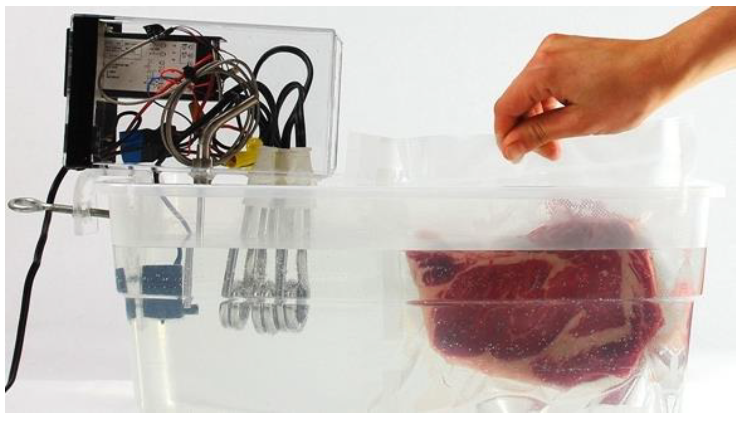
This is usually matched with the power input source in the design structure. Additionally, it comes with a safety device connecting the heat pipe to the input power. Programmable heaters are placed in water containers for time control, and the precise temperature control chip senses the water temperature and adjusts its power accordingly [6]. This allows the temperature of the food to remain constant with the water. This method has been used recently by researchers to control the temperature while water-flow heating food, as shown in Figure 2.

2.4. The Water Flow Control

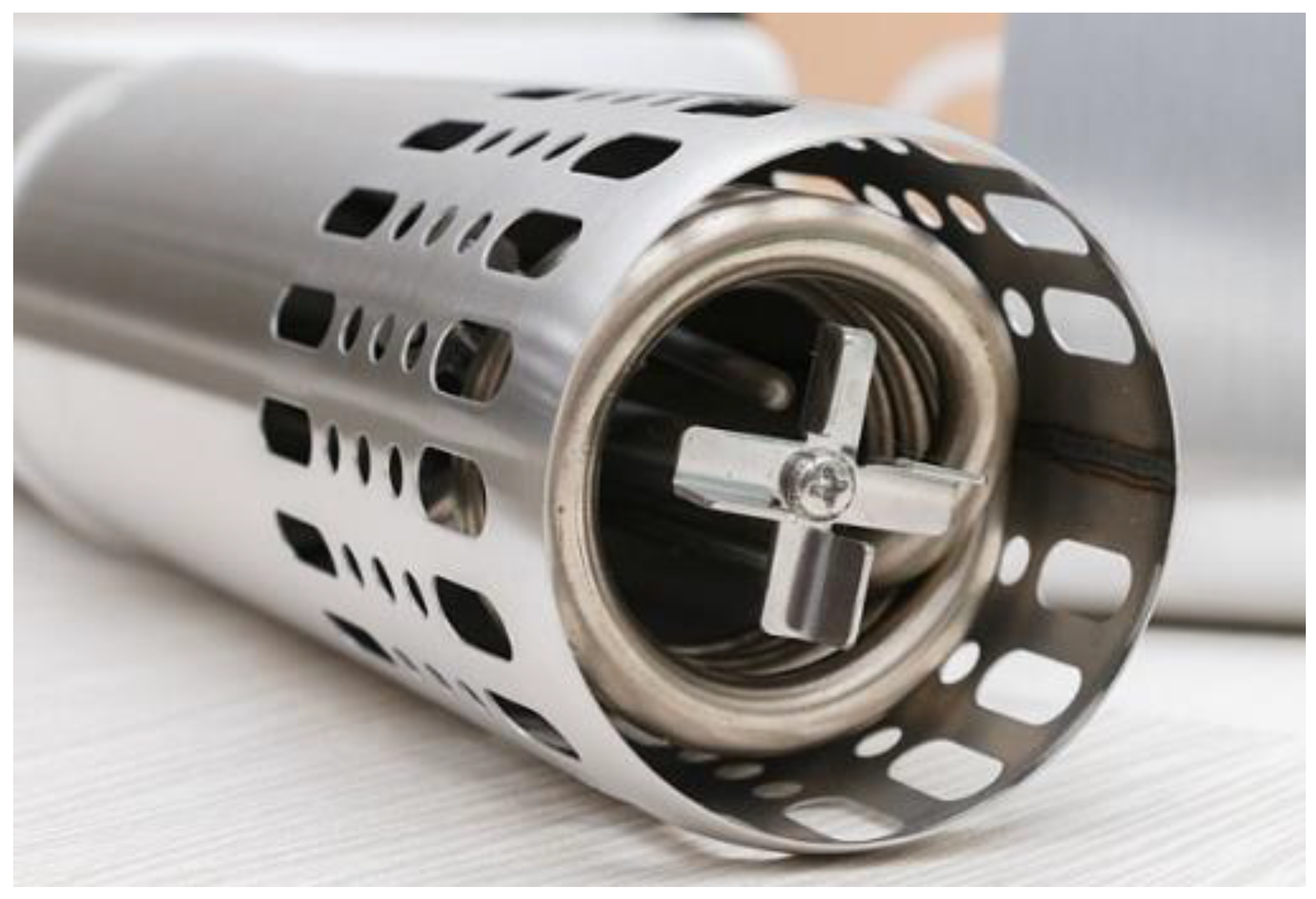
In the past, water heating control research was based on the density difference that occurs when water is heated and the natural heat convection generated when the temperature rises. By means of heat transfer, the temperature of water will gradually increase as a result of density differences and natural convection. When the temperature rises, the temperature control device cannot provide uniform performance, so a water circulation device must be added to create effective temperature control. Currently, a centrifugal pump is used to circulate the water [12], and the hydraulic performance of the pump is greatly affected by the design of the impeller [13], resulting in an even temperature distribution, as shown in Figure 3.
As shown in the structural design of the centrifugal pump, the top row of holes is the inlet for the water flow, and the middle row of circles represents the heating device. In the bottom row of holes, there is a water outlet, and the propeller speeds up the flow of water so a flow circulation can occur. This method not only allows the temperature to rise more evenly but also keeps the food evenly heated.

2.5. The Heating Efficiency of Water Heating and Circulating

As described in Section 2.3 and Section 2.4, the current water heating and circulating system is primarily composed of a heating device and a centrifugal pump. In operation, the output power of the heating device is mostly controlled by temperature feedback, while water circulation is handled by the centrifugal pump at full speed. The heating process of the system depends on setting a predetermined water temperature for heating the food.
In the general design, a simple closed-loop control system is used to achieve a stable water temperature output. By PID regulation, the output temperature is controlled by monitoring the water temperature via the sensor. As compared with the open-loop control, this system has an improved stable temperature control. Even though this is a relatively straightforward method of operation, the heat energy for heating the food comes from an electrical device, so it will be concentrated around the design. After reaching the target temperature, this heating method will use significantly less power. Additionally, this power is only used to replenish the heat lost at ambient temperature.
However, note that in this method of heating, the overall temperature of the water is easily affected by the circulation of the water flow. This will actually result in unstable water temperature control and poor heating efficiency. The optimization of water heating and circulating cannot be achieved without dynamic control of the water flow. According to research on different types of centrifugal pumps, methods for energy saving and analysis have been proposed [14]. The control of the driving motor’s duty point for the centrifugal pump has also been explored to achieve the best efficiency [15]. Therefore, it is necessary to balance heater power and pump power with different temperature settings and pot volumes, and there is still room for improving the Sous-Vide Cooker efficiency. Energy-saving research has been extensively developed in various fields. For instance, solar water heating (SWH) systems achieve energy management goals by controlling auxiliary heaters [16]. Residential heat pump water heaters (HPWH) absorb energy from the surrounding air to increase the water temperature, thereby improving efficiency and providing air conditioning benefits [17]. Another example is the Unmanned Aerial Vehicle (UAV) Flight and Hover Energy Harvesting (EFH-EH) scheme [18]. In the application of home appliances, analysis and research have also been conducted on induction heating (IH) rice cookers [19]. In addition, for microwave ovens, there are also types of research proposing automatic calibration procedures to improve energy efficiency during operation [20]. In the industrial field, the energy model is analyzed according to ISO 5048, and offline and online parameters are used to identify a new energy model for optimization, allowing the belt conveyor to achieve its best operating efficiency [21].
In the past, there was no literature on the optimal efficiency control of water heating and circulating systems. For this reason, we refer to the energy-saving research of motors and renewable energy systems, where the model-based method is used to determine the optimal power factor for the induction motors, and the power factor is controlled to achieve the lowest loss [22,23]. However, this method needs to obtain the correct parameters of the motor model. In addition, there is also an advanced control method for optimal power tracking of the induction motors [24]. Despite not requiring motor parameters, this method requires high-speed computing capabilities and is costly because the calculation content is complex. Moreover, the permanent magnet synchronous motor (PMSM) used in electric vehicles uses the maximum torque-to-current ratio as the main strategy for optimizing energy efficiency. This strategy does not depend on motor parameters and is not affected by changes in motor parameters [25].
According to the difference in luminance levels in solar energy systems, maximum power point tracking (MPPT) [26,27,28] can be used to determine the maximum output power. This method does not require battery parameters and relies on simple logic judgments and perturbation to track the maximum output power. In addition, the MPPT method will be applied to integrated PV systems along with five control techniques to optimize the maximum power point tracking (MPPT) procedure [29]. These techniques involve utilizing the MPPT method to extract the maximum power from photovoltaic modules under varying solar irradiation and temperatures, ultimately ensuring maximum power delivery at any given moment. The Solar Water Pump utilizes a Modified Active-Power Model Reference Adaptive System (MRAS) for maximum power control [30]. Additionally, studies have been conducted on full power tracking for wind power generation systems [31,32].
In this study, the pump and heater are controlled to maximize the water heating and circulating’s heating efficiency, simultaneously. We will propose a water heating and circulating system model [33,34], refer to the method of maximum power tracking, and propose a method of minimum input power tracking. During heating, this method perturbs the pump speed to track the minimum input power. The method has the characteristics of not needing the parameters of the water heating and circulating system, will not increase system resources and costs, and will have energy-saving benefits.

3. The LPPT Method

This section describes the lowest power point tracking (LPPT) algorithm proposed in this study, which is a control strategy applied to an energy-efficient heating system. In this method, the heating module of the system consists of a heater and a pump, both of which consume energy to achieve uniform heating. When the system reaches the target temperature and enters a steady state, the system will reduce the total power consumption of the heater and the pump by adjusting the pump velocity and calculating the optimal pump speed through the mathematical model derived in this section. By adjusting the pump speed, the energy consumption of the pump can be reduced. For verification, this method is also applied to a low-temperature system. In addition to achieving the optimal efficiency point, this method can achieve energy-saving benefits under long-term use.
As a starting point, the approach begins with a physical equation model of a water heating and circulating system. Compared to regular heating, water heating and circulating has a different energy consumption profile because of the long running time. Therefore, this study proposes the LPPT method for optimizing input power control, which can effectively reduce energy consumption by up to 10%, as verified by simulated experiments.

3.1. Water Heating and Circulating System and LPP

Figure 4 shows the water heating and circulating system architecture, which includes a heat generation module and a thermal load module. The heat generation module (Sous-Vide Cooker) is composed of a heater and a pump, and the inputs are heater input power Ph and pump speed ω, respectively, to generate heat Qg. The heat load includes the heat content of the water in the pot, the heat loss Qo from the external environment, and the heat absorption Qfd of the internal heating foods. The heat balance equation for the system is established by Formula (1), where Tw is the water temperature, T ˙ w represents the derivative of water temperature with respect to time, and Cw is the heat content of the water in the pot.
T ˙ w = 1 C w ( Q g -   Q f d Q o )
The heat Qg output by the Sous-Vide Cooker is shown in Formula (2), and it is obtained by multiplying the difference between the heater temperature and the tank water temperature by the pump flow rate. Here, w is the output flow of the pump, S w is the specific heat of water, and Th is the output temperature of the heater. The heater temperature Th is controlled by the input power Ph, and the pump flow w is controlled by the pump motor speed ω.
Q g = m w ˙ S w   ( T h - T w )
The heater has three parameters: C h is its heat capacity, P h is its input power, and kh is its heat transfer coefficient, and the calculation of the output temperature T h of the heater is shown in Formula (3).
T ˙ w = 1 C h ( P h   k h T h )
For the calculation of the pump flow rate, it is a function of the pump motor speed ω, as shown in Formula (4), where ρ is the water density, Ag is the area of the pump outlet, and r is the radius of the pump fan blade radius. In this example, the transient change in pump flow can be ignored because the time constant of pump flow is much smaller than the time constant of water temperature heating.
m w ˙ =   ρ   A g   r   ω
The above is the establishment of the heating model of the Sous-Vide Cooker. Next, we will explain the model of the pot and heating foods. The heat lost Qo by the pot to the outside includes the convective heat Qcv to the outside, which is expressed as in (5), and the heat conduction heat Qcd between the pot and the outside is shown in Equation (6).
Q cv = A cv h cv ( T w T air )
Q cd = A cd k cd ( T w T o )
where Acv is heat convection area, hcv is heat convection coefficient, Tair is ambient temperature for heat convection, Acd is heat transfer area, kcd is heat transfer coefficient, and To is ambient temperature for heat conduction. In order to define the heat absorption capacity of the tabletop and air surrounding the pot shell, Equation (6) assumes a conduction distance of 1 m and multiplies it by kcd to simplify the calculation model. Finally, calculate the heat absorption Qfd of the heating foods, as shown in (7) and (8), where Rfd is the thermal resistance of the ingredients, and Tf and Cfd are the temperature and heat capacity of the foods, respectively.
  Q f d = 1 R f d ( T w   T f )
T ˙ f = 1 C f d Q f d
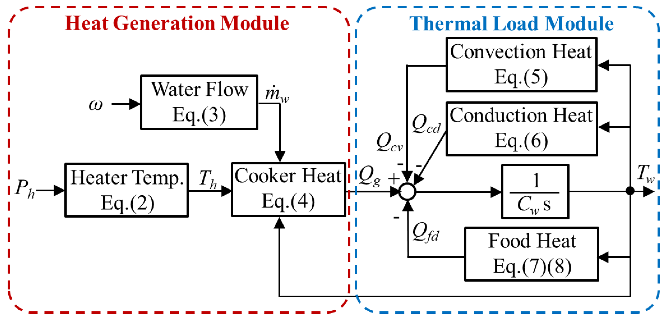
By organizing the interconnections between Formulas (1)~(8), the block diagram of the water heating and circulating system can be derived, as shown in Figure 5.
Food has a long maturation period when using the water heating and circulating method. In this way, the overall operating efficiency can be effectively improved if it can be controlled in a steady state at the lowest input power point. In general, the Sous-Vide Cooker’s input power is primarily used to heat the water and food in the pot because the heater and pump motor consume most of it. The heater’s input power is approximately ten times the pump motor’s rated power. When heating, both the heater and the pump motors operate at maximum power to provide maximum Qg for the water temperature to be quickly heated to the desired level. As the water temperature reaches its target, the demand for Qg decreases. Heater input power drops to less than about four times pump motor-rated power. It is possible to optimize the system’s efficiency by controlling the pump motor speed as the proportion of pump motor power increases in relation to the total input power.
The input power of the Sous-Vide Cooker primarily drives the heating element and pump motor, both of which play a key role in heating the water and heating the food within the heating pot. When the temperature control reaches a state of stability, the input power Ph of the heater can be computed using Formulas (2)–(4), as depicted in Formula (9). It can be observed that Ph is inversely proportional to the pump motor speed ω.
P h = k h   T h = k h   Q g S w   ρ   A g   r ω - 1 + k h   T w
where the pump power Pm is directly proportional to the cube of the pump motor speed ω [28]. The pump power Pm is shown in (10), where Tm is the output torque of the pump motor, Tm = w*ω.
P m = T m ω =   ρ   A g r 3 ω 3
The total input power Pin of the system can be expressed as shown in Formula (11), which clearly reveals that Pin is a function of the pump speed ω. By taking the differentiating of the input power with respect to the pump speed, the minimum input power point can be obtained when the condition of dPin/dω equals zero.
P i n = P h + P m = k h   Q g S w   ρ   A g   r ω - 1 + k h T w + ρ   A g r 3 ω 3
The pump speed ωLPP, corresponding to the minimum input power point, is represented in Formula (12). Upon reaching a state of steady temperature control, the output power Qg of the Sous-Vide Cooker only has to be responsible for compensating for heat loss due to conduction and convection within the heating pan. In this scenario, Formula (12) can be applied as Qg = Qcd + Qcv.
ω L P P = k h   Q g [ 3 S w ( ρ   A g r 2 ) 2 ] 4
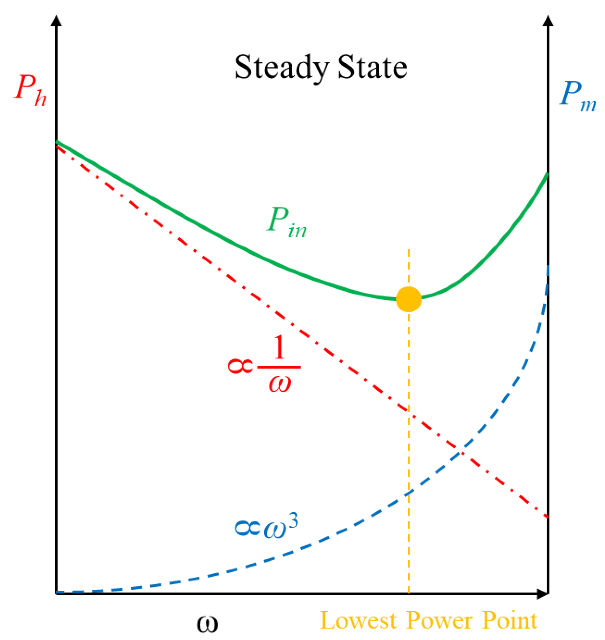
In view of the above Formula (11), we can observe that the input power Ph of the heater is inversely proportional to the rotational speed ω of the pump motor. In general, pump power Pm is proportional to pump motor speed ω3, and the relationship is shown in Figure 6. The solid line in Figure 6 shows the total input power Pin, which is calculated by summing the two parameters. With the change in pump motor speed, there will be a minimum input power point.
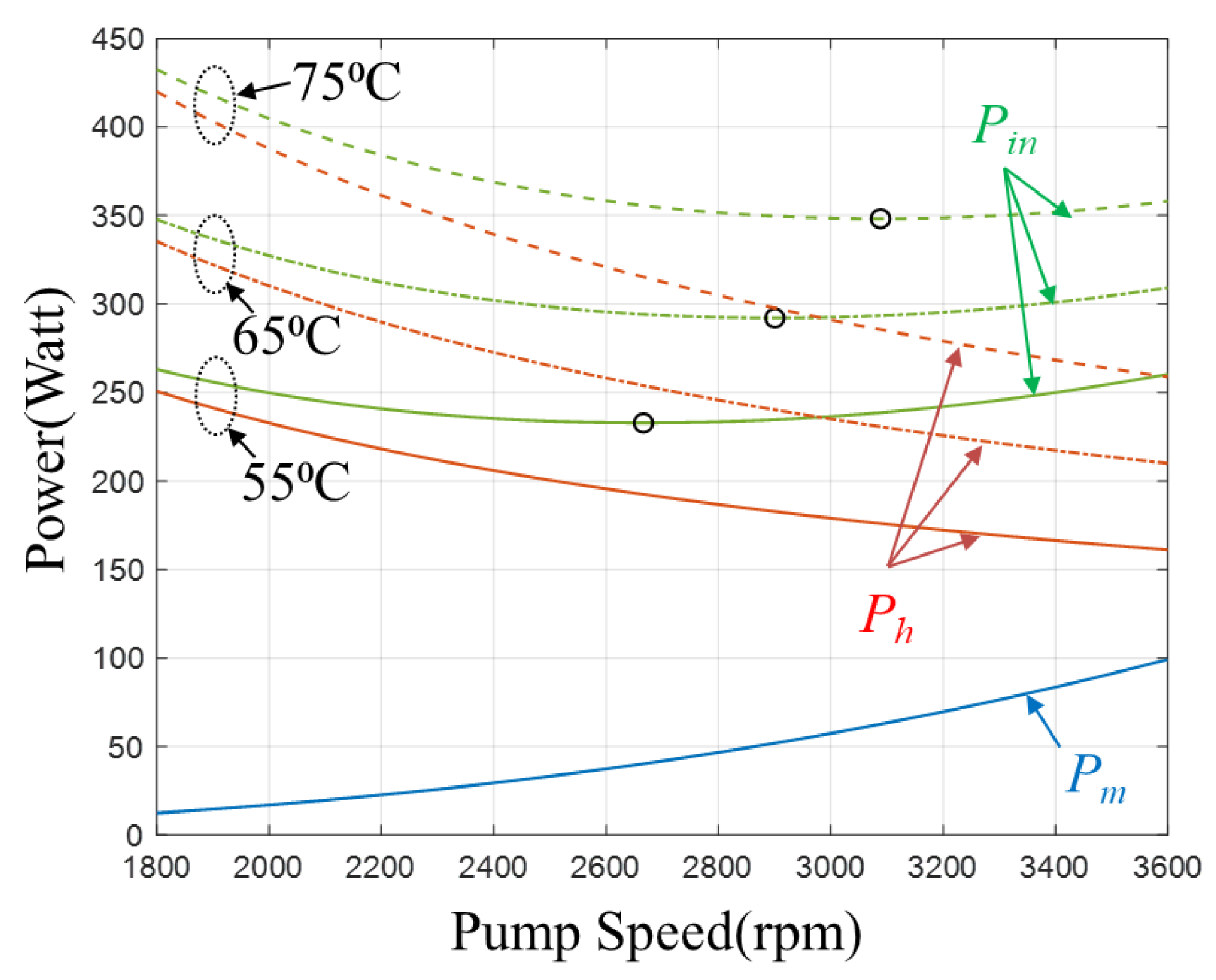
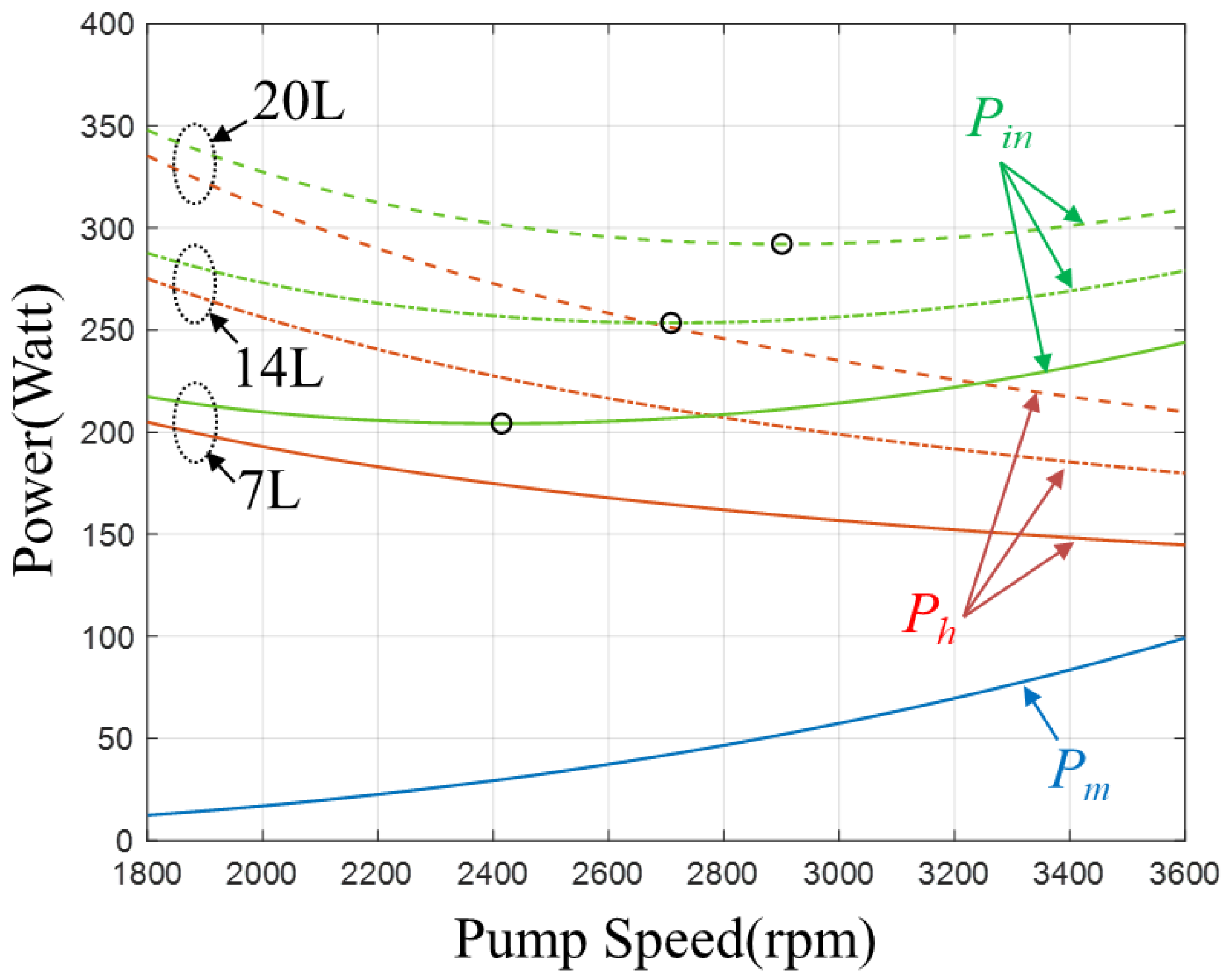
According to Formulas (9) through (12), the characteristic curves of the input power Pin, heater power Ph, and pump power Pm have been simulated and calculated in a steady state. The results are shown in Figure 7 and Figure 8, and the system parameters utilized can be found in Table 1. Figure 7 shows the relationship between power and pump speed under different temperature settings and a constant volume of 20 L. As the temperature decreases, the speed at the lowest input power point decreases correspondingly. By comparing the relationship between power and pump speed under different volumes with a constant temperature setting of 65 °C, it can be observed that the speed at the lowest input power point decreases as the volume decreases, as illustrated in Figure 8.

3.2. The Methodology of Control and Lowest Power Point Tracking

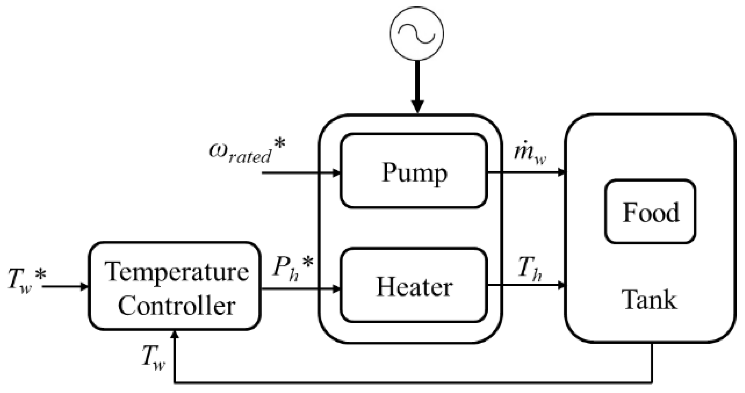
As the Sous-Vide Cooker runs, the pump circulates water, and the heater regulates the temperature of the water, which are independent of each other. The traditional heating control block diagram is shown in Figure 9. Usually, the pump runs at the rated speed of the motor and circulates with maximum output water flow. By using with a general PI controller, the water temperature is controlled to adjust the output temperature to reach the target temperature by controlling the input power of the heater.
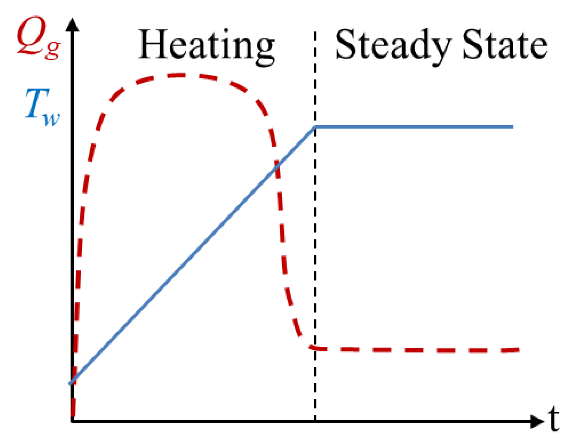
In the beginning, the Sous-Vide Cooker must overcome the water’s heat and supply heat to the foods being cooked. It operates at full power to raise the water temperature quickly and cook food to the desired level. As shown in Figure 10, a steady state of water temperature, primarily to overcome the external heat loss of the pot, will greatly reduce the demand for heating heat Qg. However, Formula (2) shows that the heating capacity Qg of the Sous-Vide Cooker is a function of the pump flow rate w and the heater temperature Th, and the two are inversely proportional to each other. That is, in the steady state, Th can be changed through the adjustment of the flow w, and the input power of the Sous-Vide Cooker can be further reduced.
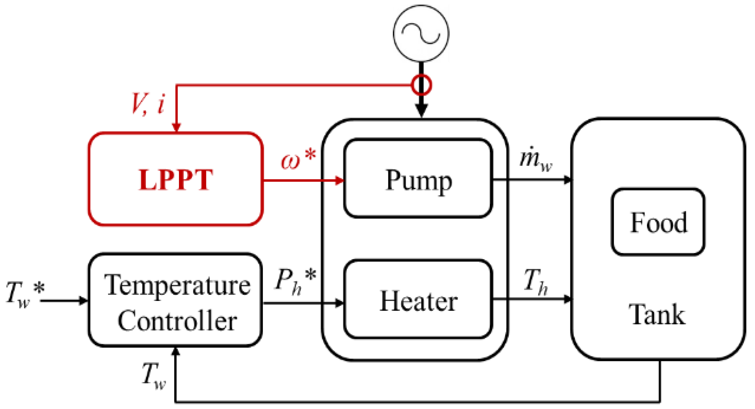
Considering Section 3.1, the combination of the water heating and circulating system environment, pots, and heating foods is complex, and determining the heat load parameters is relatively difficult. As a result, this paper presents the concept of lowest-power point tracking that can be used to find the lowest input power point by perturbing the pump motor speed without specifying the system parameters. The control block diagram is shown in Figure 11. In this case, the input parameters are the voltage V and current i of the Sous-Vide Cooker, and the output perturb is the speed of the pump motor.
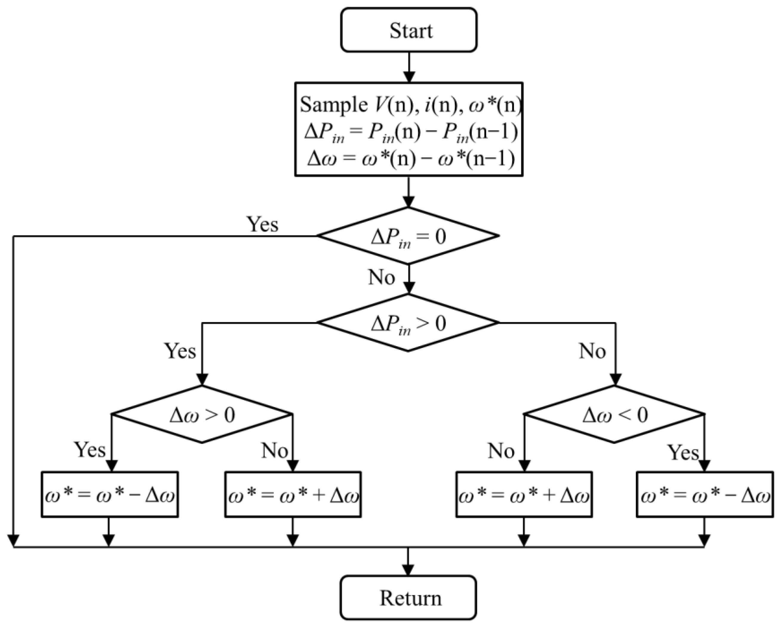
Figure 12 shows the control flow diagram of the LPPT method. To calculate the input power, the input voltage V and current i are captured first. At the same time, the pump speed command ω* is recorded, and then the input power and pump speed command variation, ΔPin and Δω, are calculated. As the positive and negative relationship between the two changes, gradually decrease the pump speed command until the system finds the lowest point of power input.

4. System Experiment Simulation

4.1. Simulation in Water Heating and Circulating System

This section presents a simulation test to verify the water heating and circulating model in this paper. In addition, this research compares the traditional Sous-Vide Cooker control method with the LPPT method and then demonstrates the benefit analysis of input power improvement, where the perturb frequency of LPPT is 1/60 Hz, and the pump speed perturbation is 100 rpm.
It is assumed the system operates in a kitchen environment, and the working temperature is 30 degrees; the parameters of convection and conduction change as the volume of the pot changes. Additionally, the parameters for heating foods will not be affected by the simulated conditions. For simulation analysis, we use the following two operating conditions. In one case, the pot volume is the same, but the target water temperature differs, and in another case, the target temperature is fixed, but there are different pot volumes.

4.2. Same Pot Volume, Different Target Temperature

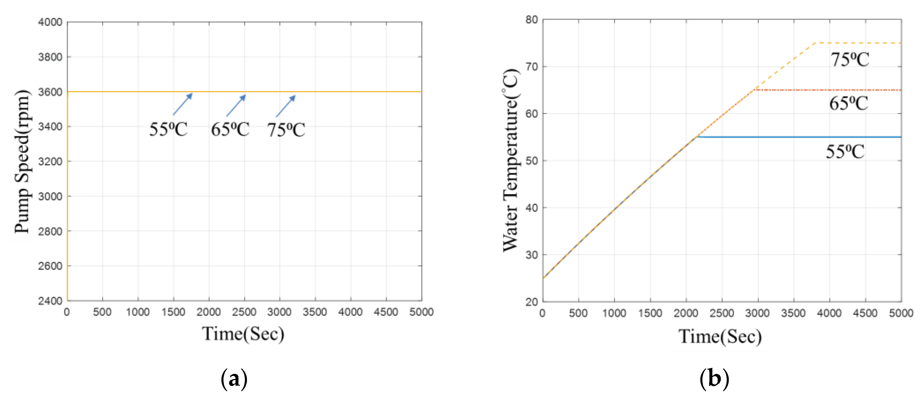
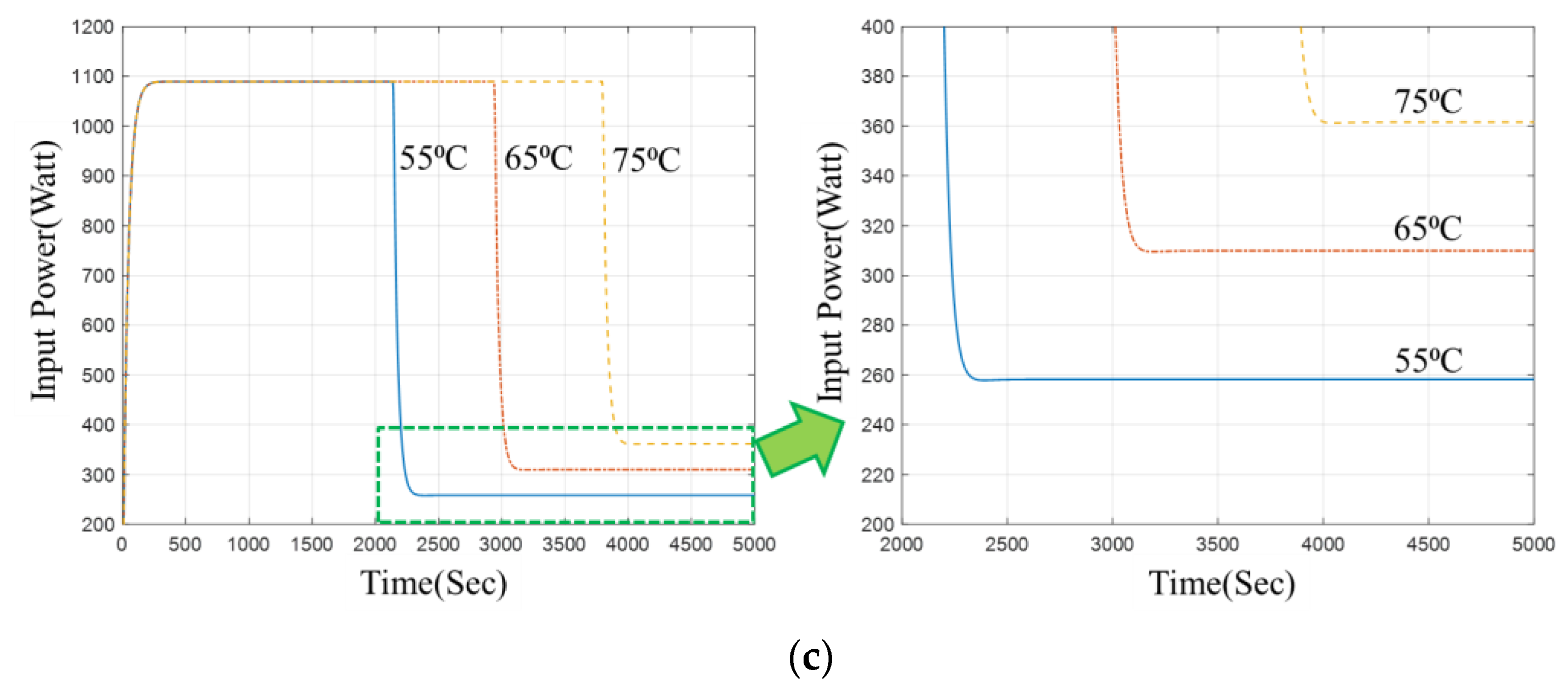
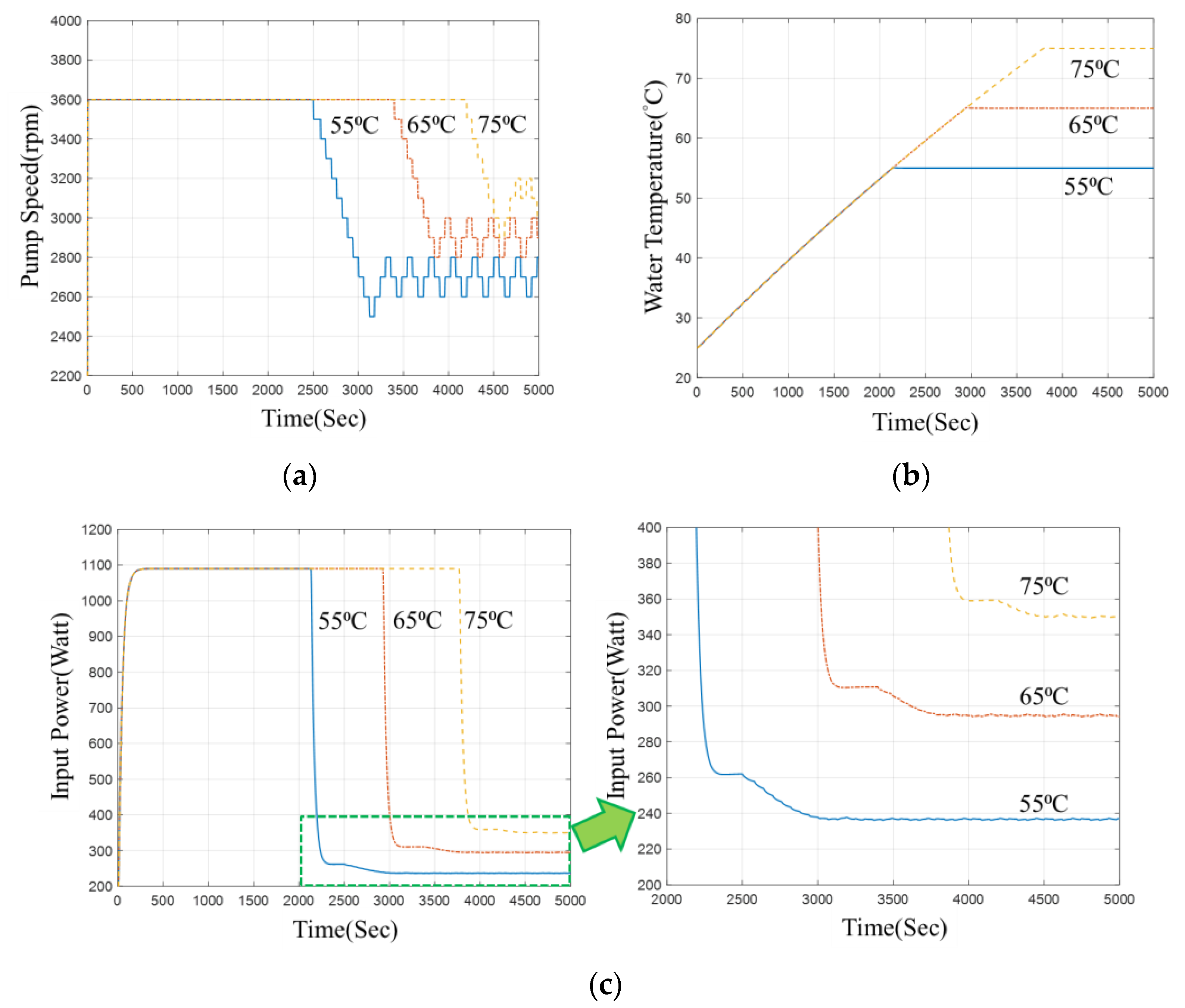
The volume of the simulated pan is set to 20 L, and the target temperatures are set to 75 °C, 65 °C, and 55 °C, respectively. To begin with, based on the description in Section 3.2, the simulation is conducted using the traditional water heating and circulating control model. Figure 13 illustrates the experimental results, in which Figure 13a represents the pump speed, and the rated speed is set to 3600 rpm. The water temperature response is shown in Figure 13b, and traditional control can be effective in reaching the target water temperature. During steady-state conditions, 358 W of input power is generated at 75 °C, 309 W at 65 °C, and 259 W at 55 °C.
The simulation result shown in Figure 14 shows the result of importing LPPT as described in Section 3.2, in which Figure 14a is the pump speed. Following the LPPT method, the pump speed is gradually perturbed from 3600 rpm once the water temperature reaches a steady state. Next, we can find the lowest power point. In Figure 14a, it can be observed that the lower the target water temperature, the lower the pump speed of the LPPT final perturbation output.
Figure 14b illustrates how temperature responds to water temperature changes. Although there is a perturbation caused by LPPT, the target water temperature can still be effectively reached. The steady-state input power is 348 W at 75 °C, 292 W at 65 °C, and 232 W at 55 °C, based on finding the lowest input power point with LPPT. It can be concluded from the comparison of input power results in Figure 13 and Figure 14 that the lower the target temperature is, the more input power can be saved.

4.3. Same Target Temperature, Different Pot Volume

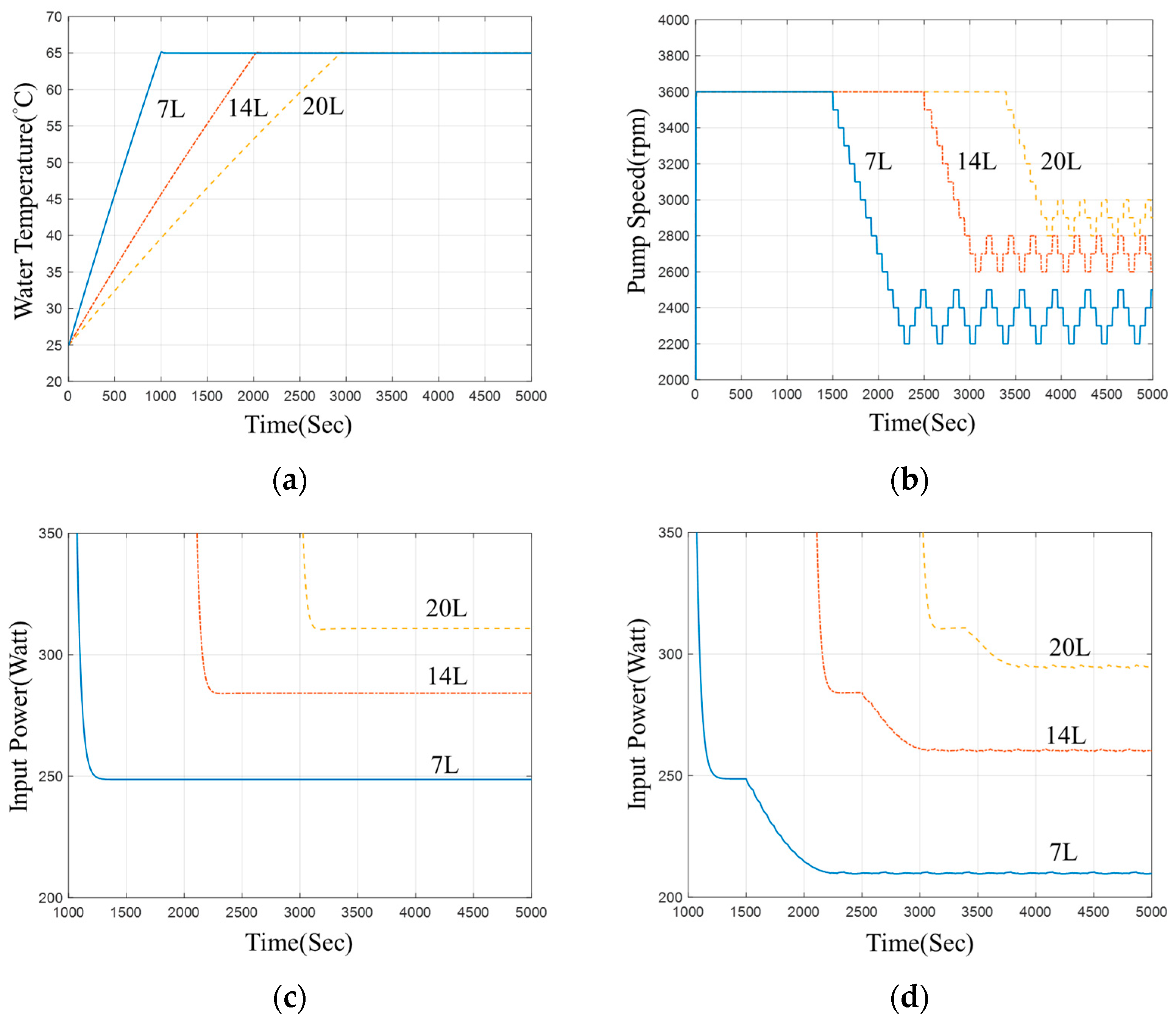
The target temperature is set to 65 °C, and the volumes of the simulated pots are set to 20 L, 14 L, and 7 L, respectively, with the simulation results being shown in Figure 15. Figure 15a shows the result of the perturbed change in pump speed when LPPT is introduced. It can be observed that the smaller the pot capacity, the lower the pump speed with the lowest input power.
Figure 15b shows that introducing LPPT can also effectively achieve the target water temperature. Figure 15c shows the input power controlled by a traditional Sous-Vide Cooker. In steady state, the required power is 309 W for 20 L, 278 W for 14 L, and 243 W for 7 L. Figure 15d shows the input power of LPPT. In a steady state, the required power is 292 W for 20 L, 253 W for 14 L, and 204 W for 7 L. By comparing the input power results in Figure 15c,d, it is possible to determine that the smaller the pot volume, the more power saved.

4.4. Simulation Result

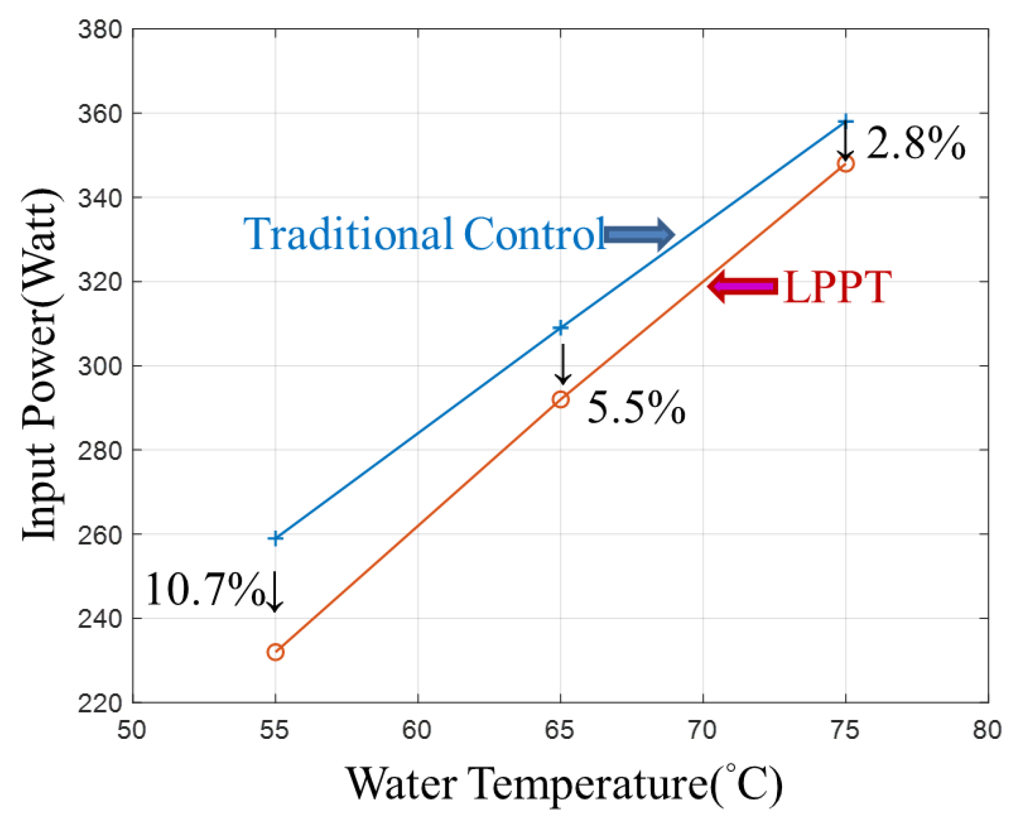
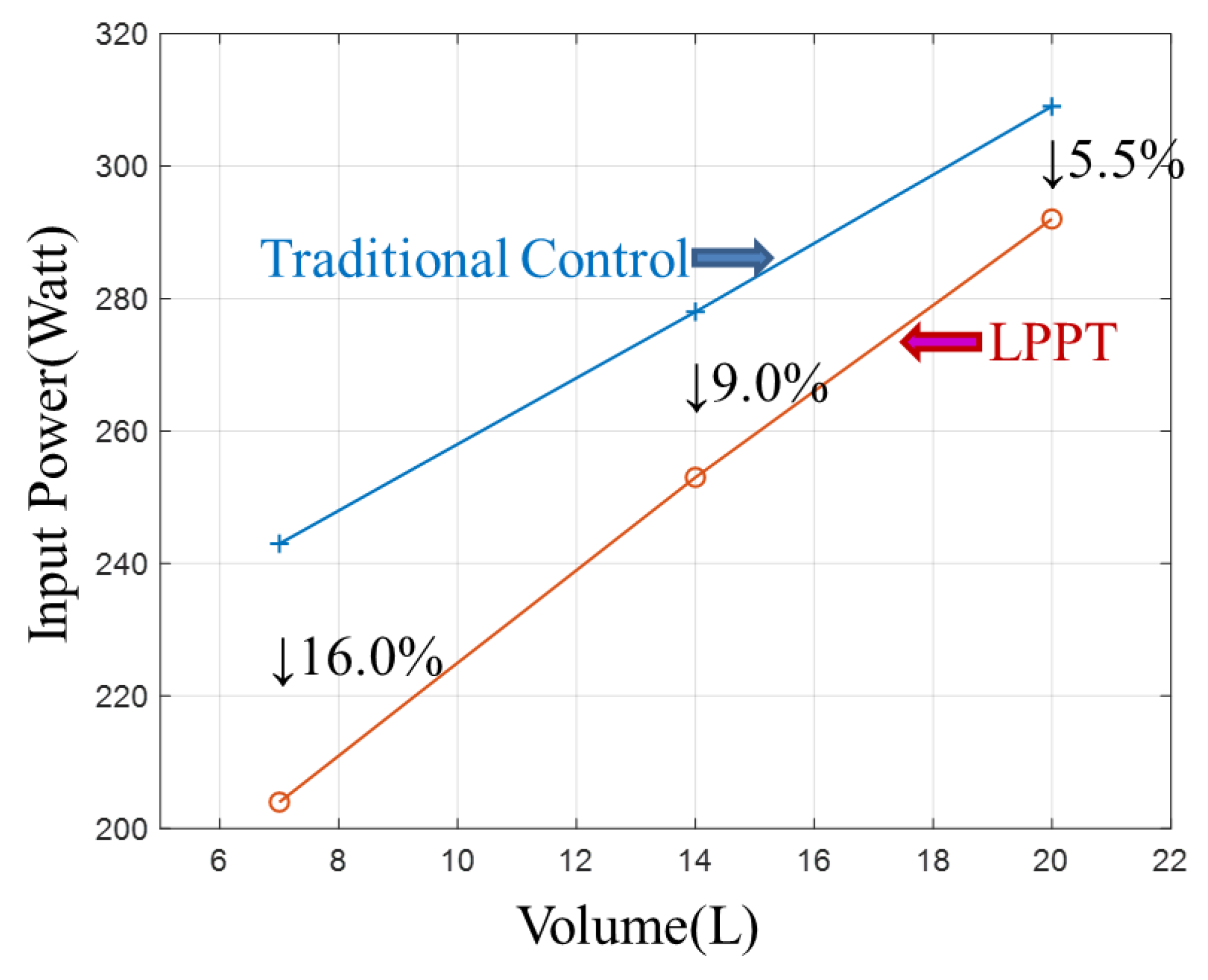
In the simulation experiment, the performance of the input power can be compared. Additionally, it is possible to analyze the power improvement results of the power input for the same pot volume and different target temperatures. As shown in Figure 16, as the target temperature decreases, the improvement ratio of the input power gradually increases, reaching up to 10.7%. Figure 17 shows the input power improvement results for different pot volumes at the same target temperature. There is a gradual increase in the improvement ratio of the input power with decreasing pot volume. As shown in Figure 17, the improvement effect of up to 16% is even more evident.

5. Following the Experimental Study

The following demonstrates how the Sous-Vide Cooker will be utilized in a water heating and circulating system. Experimentally, traditional temperature control and imported LPPT control methods are used, and a benefits analysis of optimized output power is performed and compared in this study.
The following describes the experimental environment and the power measurement system. After that, the experimental results for the control method will be presented as well as a comparison of the two in terms of benefits. Finally, the experiments demonstrate the effectiveness of the LPPT in heating at low temperatures, and a conclusion is provided.

5.1. Experimental System

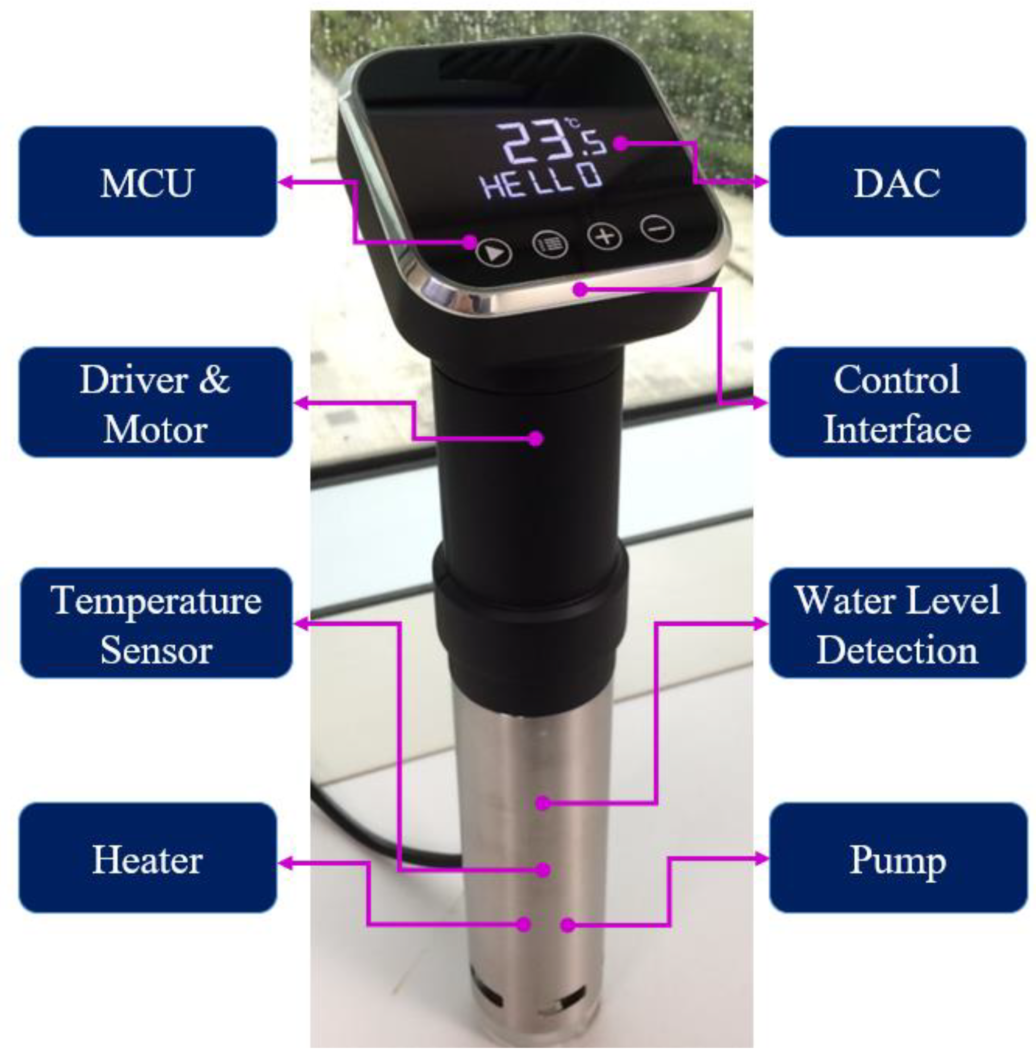
In this study, the cylinder prototype and each detail unit are shown in Figure 18 above, and the unit has a height of about 40 cm and a diameter of 6 cm. A black plastic material is used to make the upper housing of the system, which is certified for use in high-temperature food applications. The upper panel has an LED display and capacitive touch buttons, along with temperature and pump and driver controllers. This lower half of the system is made up of a metal cylinder that is primarily equipped with a 1 kW heating unit for raising the water temperature and precisely controlling the water temperature by temperature sensor with an accuracy of 0.0625 °C. The bottom contains a centrifugal pump powered by a 100 W motor system, with a flow rate of up to 6 L per minute. There is also a temperature over-protection feature and a water level detection function for ensuring the device’s safety.
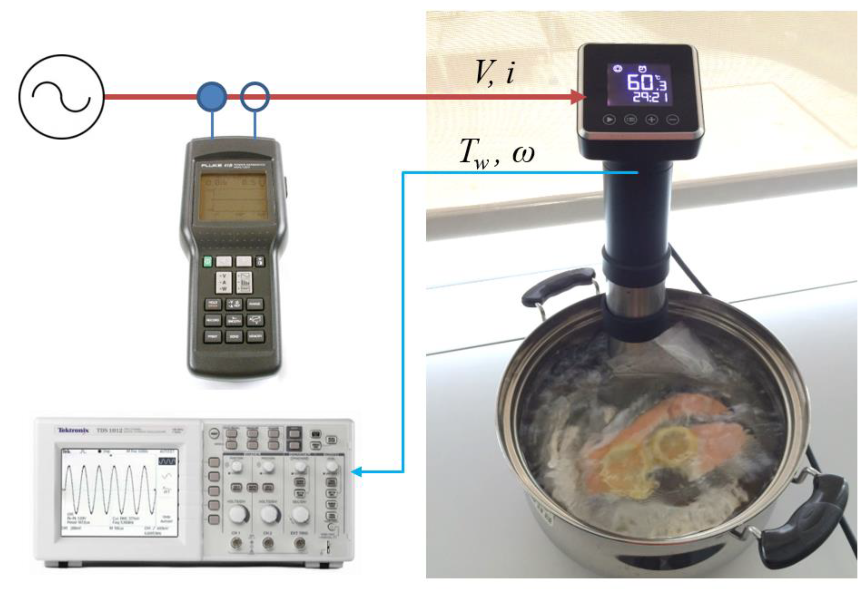
In this section, the simulation conditions in Section 4 are used as a reference application for system verification, which is described above. Figure 19 shows the overall water heating and circulating system test system. An experimental system for water heating and circulating consists of a Sous-Vide Cooker developed by this research institute and pots to cook food. By using the built-in DAC interface, the Sous-Vide Cooker outputs the water temperature and pump speed, and the FLUKE power meter measures the input power, which is displayed and recorded by the oscilloscope.
For verifying whether the simulation experiment can be carried out with the ideas proposed in this paper, the temperature and the pot size are preset according to inertia. In the experiment, 5 L, 10 L, and 15 L pots were used, and the temperatures were 55 °C, 65 °C, and 75 °C. A comparison is made between traditional and LPPT control methods, and graphs are used to show how much energy was saved and the results of the temperature control experiments. The experimental results are described in next section.

5.2. Experimental Results

This section presents the experimental results, including the traditional and LPPT temperature control methods proposed in this paper, and evaluates the energy-saving benefits of the LPPT method.
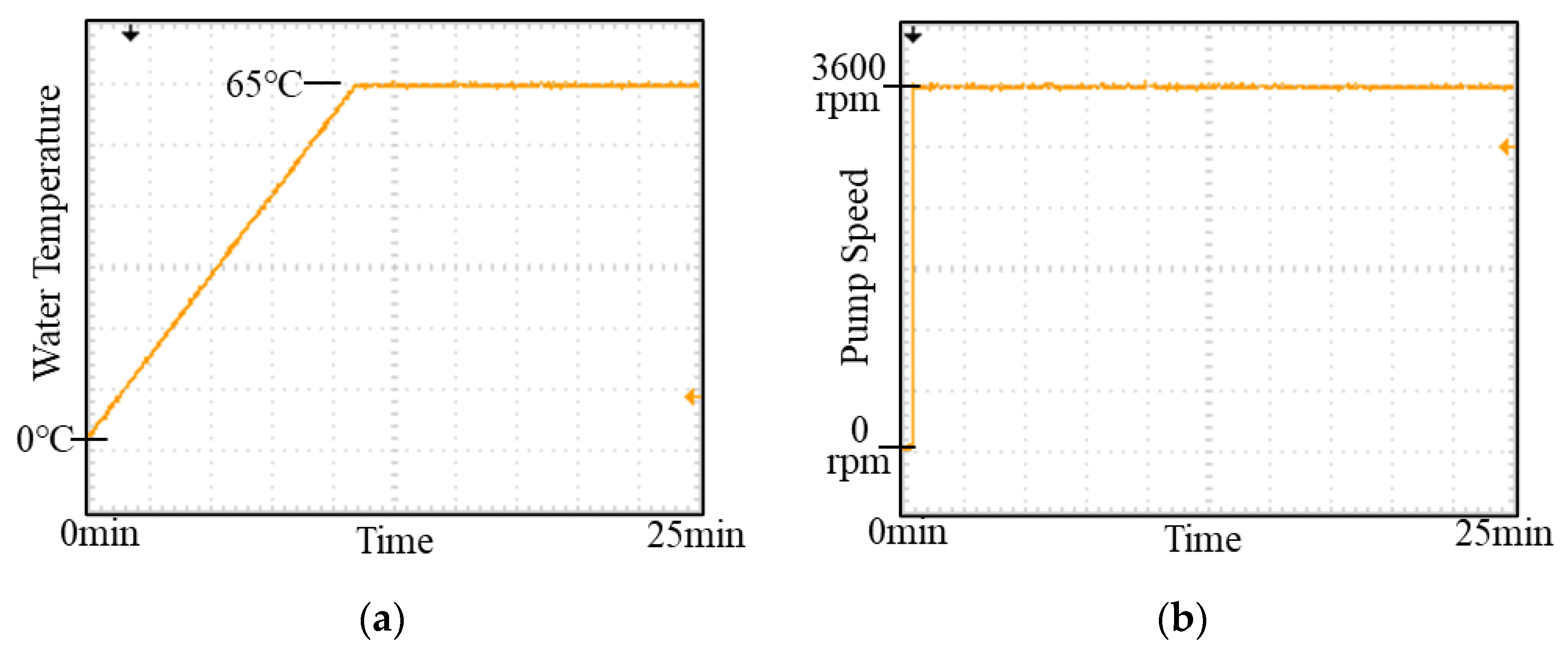
Figure 13 shows a traditional temperature control design working with a frequency of 1 Hz and a pump speed of about 3600 rpm, which is the rated speed. The target water temperature is set at 65 °C. The experimental results are shown in Figure 20, in which shows the temperature control can effectively reach 65 °C, and Figure 20a,b show the pump speed is stable at 3600 rpm. There is approximately 220 Watts of steady-state input power under these conditions.

5.3. LPPT Control Results

The verification results of the LPPT method are illustrated in this section, and the control architecture is shown in Figure 14. The temperature control frequency is also set to 1 Hz in accordance with the traditional control method. To determine the minimum input power for the pump, the LPPT control method is used to perturb the pump speed. The perturbation frequency is 1/60 Hz, and the pump speed variation of perturbation is 100 rpm. The target water temperature for the system is set at 65 °C.
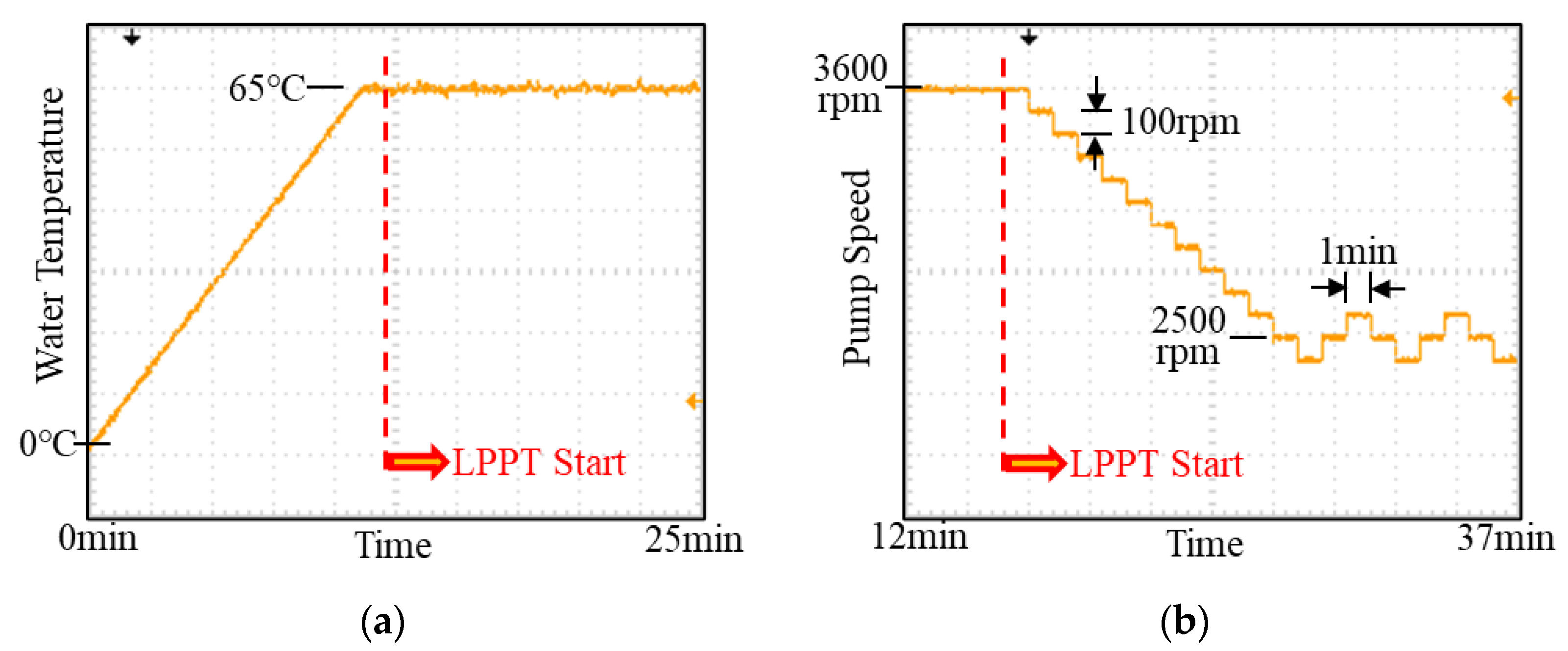
Using the LPPT control, the experimental results demonstrate even with a small ripple in temperature, the pump speed can still be controlled effectively at 65 °C, as shown in Figure 21a. By using the LPPT control, the pump speed is gradually reduced from an initial 3600 rpm to about 2500 rpm at the end of the experiment, as shown in Figure 21b. The steady-state input power under this condition is about 195 watts.

5.4. Experimental Data Comparison

A summary of the experimental results for different target temperatures and pot volumes is provided in this section. These results are shown in Table 2, Table 3 and Table 4. The results of the experiments demonstrate the LPPT method can enhance the overall efficiency of the heating system by integrating temperature control and reducing the power input requirements.
Table 2 shows the improvement effect of input power under conditions where the pot is 5 L in volume, and the temperature targets are 55, 65, and 75 °C, respectively. LPPT can increase power by 17.5%, 11.4%, and 6.4% at 55, 65, and 75 °C, respectively, compared with the traditional control method. In general, the higher the target temperature, the lower the improvement effect will be.
Table 3 shows the improvement effect of the input power under conditions where the pot is 10 L in volume and the temperature targets are 55, 65, and 75 °C, respectively. Compared with the traditional control method of LPPT, when the water temperature is 55, 65, and 75 °C, the power is increased to 8.3%, 6.1%, and 2.9%, respectively.
Table 4 shows the improvement effect of input power under conditions where the pot is 15 L in volume and the temperature targets are 55, 65, and 75 °C, respectively. Compared with the traditional control method of LPPT, when the water temperature is 55, 65, and 75 °C, the power is increased to 5.5%, 2.9%, and 1.0%, respectively. When volume increases, efficiency increases by a lower amount, and in low-temperature environments, efficiency increases by a higher amount.
The above experimental results show the LPPT method can effectively reduce the steady-state input power, and the smaller the pot and lower the target temperature, the greater the reduction. Further, the results of comparative experiments indicate the LPPT method is appropriate for water heating and circulating systems and is a significant improvement on the heating pots used on a regular basis.
In this system, food is cooked by sealing it in a vacuum bag and immersing it in water. Introducing LPPT not only increases cooking accuracy but also allows food to reach a more precise temperature, resulting in better cooking results. Water temperature is easier to control than air temperature, and once the water reaches the desired temperature, the food also reaches the same temperature. The vacuum-sealed bag prevents food moisture loss, thus preserving its original flavor and texture and providing low-temperature cooking benefits. Cooking food in water reduces energy waste, as water can transfer and retain heat more efficiently than air, leading to a reduction in energy consumption. Therefore, in addition to the optimal power characteristics of this study, the ease of heat transfer and retention in water also reduces energy consumption.

6. Conclusions and Discussion

In recent years, water heating and circulating has become a mainstream practice for maintaining a healthy diet. A brief history of its development and its heating characteristics is presented in this paper. At present, the key device, the Sous-Vide Cooker, primarily consists of a heater and a pump. The input power of the heater is controlled by the system, but the pump speed is not changed. According to the simulation and experimental results, since the Sous-Vide Cooker pump only operates at rated speeds, the pump is always kept running at the highest power operation, resulting in a non-optimal system input power. The longer the heating time, the more energy wasted.
In this study, a novel water heating and circulating control framework is introduced for the first time with the creative idea of pump speed perturbation. As well as automatically finding the lowest input power, LPPT can also optimize the efficiency of the water heating and circulating system by controlling the heater and pump when it is running. By reducing energy consumption and avoiding the issue that long-term heating is also affected by pump power, LPPT can reduce the energy consumption of the Sous-Vide Cooker.
The main contribution of this research is that LPPT calculates the real-time input power based on the input voltage and current, and it can achieve the most efficient input power by perturbing the pump speed. This method simplifies the calculation of energy consumption of the Sous Vide Cooker, since it does not need to calculate the ingredients or other system parameters in the water heating and circulating system. The experimental results show that applying the LPPT method to daily pot capacity can reduce the input power by over 17%. Besides its practical use for healthy heating, Sous-Vide Cookers with LPPT are also energy efficient. The LPPT proposed in this article is designed for a low-temperature cooking system, and the tank volume will increase with the amount of foods used. It is suitable for high-power heating devices and pumps, and it can also be applied in commercial and industrial settings. By implementing the best power point design, the LPPT method can achieve the maximum energy conversion efficiency.

Author Contributions

Conceptualization, F.-C.L. and C.-S.C.; methodology, F.-C.L. and C.-S.C.; software, F.-C.L.; validation, F.-C.L.; formal analysis, C.-S.C.; investigation, C.-J.L. and F.-C.L.; resources, C.-S.C.; data curation, C.-J.L.; writing—original draft preparation, F.-C.L. and C.-J.L.; writing—review and editing, C.-J.L. and F.-C.L.; visualization, C.-J.L.; supervision, F.-C.L.; project administration, C.-S.C.; funding acquisition, C.-S.C. All authors have read and agreed to the published version of the manuscript.

Funding

This research received no external funding.

Institutional Review Board Statement

Not applicable.

Informed Consent Statement

Not applicable.

Data Availability Statement

The data presented in this study are available upon request from the corresponding author.

Acknowledgments

The test device was support by TECO Electric & Machinery Company Ltd.

Conflicts of Interest

The authors declare no conflict of interest.

References

  1. Pérez-Lloréns, J.L. Cooking-Science-Communication (CSC): The ideal trident to enjoy the dining experience. Int. J. Gastron. Food Sci. 2019, 16, 100134. [Google Scholar] [CrossRef]
  2. Sörensen, P.M.; Mouritsen, O.G. Science education and public understanding of science via food, cooking, and flavour. Int. J. Gastron. Food Sci. 2019, 15, 36–47. [Google Scholar] [CrossRef]
  3. Ateş, E.; Unal, K. The effects of deep-frying, microwave, oven and sous vide cooking on the acrylamide formation of gluten-free chicken nuggets. Int. J. Gastron. Food Sci. 2023, 31, 100666. [Google Scholar] [CrossRef]
  4. Ilic, J.; Tomasevic, I.; Djekic, I. Purple eggplant and zucchini color, mechanical properties, mastication, and sensory perception influenced by steaming and Sous-vide. Int. J. Gastron. Food Sci. 2022, 28, 100549. [Google Scholar] [CrossRef]
  5. Myhrvold, N.; Young, C.; Bilet, M. Modernist Cuisine: The Art and Science of Cooking; The Cooking Lab: Port Washington, NY, USA, 2011. [Google Scholar]
  6. Baldwin, D.E. Sous Vide Cooking: A Review. Int. J. Gastron. Food Sci. 2012, 1, 15–30. [Google Scholar] [CrossRef] [Green Version]
  7. Schellekens, M. New Research Issues in Sous-Vide Cooking. Trends Food Sci. Technol. 1996, 7, 256–262. [Google Scholar] [CrossRef]
  8. Tornberg, E. Effect of Heat on Meat Proteins—Implications on Structure and Quality of Meat Products. Meat Sci. 2005, 70, 493–508. [Google Scholar] [CrossRef]
  9. Nel, P.J.C.; Booysen, M.J.; van der Merwe, B. A Computationally Inexpensive Energy Model for Horizontal Electric Water Heaters with Scheduling. IEEE Trans. Smart Grid 2018, 9, 48–56. [Google Scholar] [CrossRef]
  10. Wu, M.; Bao, Y.Q.; Zhang, J.; Ji, T. Multi-objective optimization for electric water heater using mixed integer linear programming. J. Mod. Power Syst. Clean Energy 2019, 7, 1256–1266. [Google Scholar] [CrossRef] [Green Version]
  11. Chakraborty, S.; Bera, S.K.; Bera, S.C.; Mandal, N. Design of a Simple Temperature Transmitter Circuit of an Electric Heater Operated Water Bath. IEEE Sens. J. 2018, 18, 3140–3151. [Google Scholar] [CrossRef]
  12. Badr, H.M.; Ahmed, W.H. Pumping Machinery Theory and Practice; Wiley: Hoboken, NJ, USA, 2015. [Google Scholar]
  13. Fang, H.; Ma, J.; Zhang, W.; Yang, H.; Chen, F.; Li, X. Hydraulic Performance Optimization of Pump Impeller Based on a Joint of Particle Swarm Algorithm and Least-Squares Support Vector Regression. IEEE Access 2020, 8, 203645–203654. [Google Scholar] [CrossRef]
  14. Armintor, J.K.; Connors, D.P. Pumping Applications in the Petroleum and Chemical Industries. IEEE Trans. Ind. Appl. 1987, 23, 37–48. [Google Scholar] [CrossRef]
  15. Tarhan, Ü.; Selim, E.; Akın, Ö. Determination and Functional Implementation of Operating Point of a Centrifugal Pump With BLDC Motor. IEEE Can. J. Electr. Comput. Eng. 2022, 45, 105–113. [Google Scholar] [CrossRef]
  16. Li, W.T.; Thirugnanam, K.; Tushar, W.; Yuen, C.; Chew, K.T.; Tai, S. Improving the Operation of Solar Water Heating Systems in Green Buildings via Optimized Control Strategies. IEEE Trans. Ind. Inform. 2018, 14, 1646–1655. [Google Scholar] [CrossRef]
  17. Hepbasli, A.; Kalinci, Y. A review of heat pump water heating systems. Renew. Sustain. Energy Rev. 2009, 13, 1211–1229. [Google Scholar] [CrossRef]
  18. Ye, H.T.; Kang, X.; Joung, J.; Liang, Y.C. Optimization for Wireless-Powered IoT Networks Enabled by an Energy-Limited UAV Under Practical Energy Consumption Model. IEEE Wirel. Commun. Lett. 2021, 10, 567–571. [Google Scholar] [CrossRef]
  19. Kim, D.S.; So, J.Y.; Kim, D.K. Study on Heating Performance Improvement of Practical Induction Heating Rice Cooker With Magnetic Flux Concentrator. IEEE Trans. Appl. Supercond. 2016, 26, 0604304. [Google Scholar] [CrossRef]
  20. Monzó-Cabrera, J.; Pedreño-Molina, J.L.; Toledo, A. Feedback control procedure for energy efficiency optimization of microwave-heating ovens. Measurement 2009, 42, 1257–1262. [Google Scholar] [CrossRef] [Green Version]
  21. Zhang, S.; Xia, X. Modeling and energy efficiency optimization of belt conveyors. Appl. Energy 2011, 88, 3061–3071. [Google Scholar] [CrossRef] [Green Version]
  22. Kioskeridis, I.; Margaris, N. Loss Minimization in Induction Motor Adjustable-Speed Drives. IEEE Trans. Ind. Electron. 1996, 43, 226–231. [Google Scholar] [CrossRef]
  23. Yang, S.M.; Lin, F.C. Loss-Minimization Control of Vector-Controlled Induction Motor Drives. J. Chin. Inst. Eng. 2003, 26, 37–45. [Google Scholar] [CrossRef]
  24. Bose, B.K.; Patel, N.R.; Rajashekara, K. A Neuro-Fuzzy-Based On-Line Efficiency Optimization Control of a Stator Flux-Oriented Direct Vector-Controlled Induction Motor Drive. IEEE Trans. Ind. Electron. 1997, 44, 270–273. [Google Scholar] [CrossRef] [Green Version]
  25. Lu, Y.; Jiang, Z.; Chen, C.; Zhuang, Y. Energy efficiency optimization of field-oriented control for PMSM in all electric system. Sustain. Energy Technol. Assess. 2021, 48, 101575. [Google Scholar] [CrossRef]
  26. Abu-Rub, H.; Malinowski, M.; Al-Haddad, K. Photovoltaic Energy Conversion Systems; Wiley-IEEE Press: Hoboken, NJ, USA, 2014. [Google Scholar]
  27. Boztepe, M.; Guinjoan, F.; Velasco-Quesada, G.; Silvestre, S.; Chouder, A.; Karatepe, E. Global MPPT Scheme for Photovoltaic String Inverters Based on Restricted Voltage Window Search Algorithm. IEEE Trans. Ind. Electron. 2014, 61, 3302–3312. [Google Scholar] [CrossRef]
  28. Sangwongwanich, A.; Blaabjerg, F. Mitigation of Interharmonics in PV Systems With Maximum Power Point Tracking Modification. IEEE Trans. Power Electron. 2019, 34, 8279–8282. [Google Scholar] [CrossRef] [Green Version]
  29. Fathi, T.; Houda, J.; Abdelkader, M.; Khedher, N.B.; Aich, W.; Boudejemline, A.; Boujelbene, M. Comparative assessment between five control techniques to optimize the maximum power point tracking procedure for PV systems. Mathematics 2022, 10, 1080. [Google Scholar]
  30. Kashif, M.; Singh, B. Modified Active-Power MRAS Based Adaptive Control With Reduced Sensors for PMSM Operated Solar Water Pump. IEEE Trans. Energy Convers. 2023, 38, 38–52. [Google Scholar] [CrossRef]
  31. Balbino, A.J.; Nora, B.d.S.; Lazzarin, T.B. An Improved Mechanical Sensorless Maximum Power Point Tracking Method for Permanent-Magnet Synchronous Generator-Based Small Wind Turbines Systems. IEEE Trans. Ind. Electron. 2022, 69, 4765–4775. [Google Scholar] [CrossRef]
  32. Huynh, P.; Tungare, S.; Banerjee, A. Maximum Power Point Tracking for Wind Turbine Using Integrated Generator–Rectifier Systems. IEEE Trans. Power Electron. 2021, 36, 504–512. [Google Scholar] [CrossRef]
  33. Eronini, U.-E. System Dynamics and Control; PWS Publishers: Pacific Grove, CA, USA, 1998. [Google Scholar]
  34. Roffel, B.; Betlem, B. Process Dynamics and Control: Modeling for Control and Prediction; Wiley: Hoboken, NJ, USA, 2007. [Google Scholar]
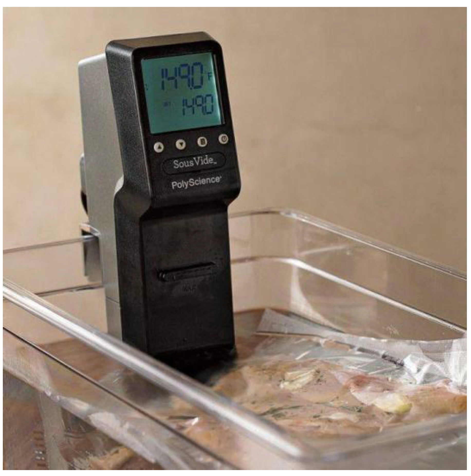
Figure 1. Sous-Vide Cooker product (from PolyScience).
Applsci 13 05542 g001
Figure 2. Thermostats for controlling the temperature of food and water (from seattlefoodgeek.com (1 February 2020).
Applsci 13 05542 g002
Figure 3. Centrifugal pump structure (from PENGFA).
Applsci 13 05542 g003
Figure 4. The water heating and circulating system architecture.
Applsci 13 05542 g004
Figure 5. The water heating and circulating system block diagram.
Applsci 13 05542 g005
Figure 6. Curves of total input power and operating power of heaters and pumps.
Applsci 13 05542 g006
Figure 7. Power–speed relationship with constant volume (20 liters) and varying temperatures, denoted by minimum input power point ‘o’.
Applsci 13 05542 g007
Figure 8. Power–speed relationship with constant temperature (65 °C) and varying volumes, denoted by minimum input power point ‘o’.
Applsci 13 05542 g008
Figure 9. Traditional water heating and circulating control block diagram.
Applsci 13 05542 g009
Figure 10. An illustration of the temperature change curve for heating and cooling water.
Applsci 13 05542 g010
Figure 11. LPPT control block diagram.
Applsci 13 05542 g011
Figure 12. Control flow diagram of the LPPT method.
Applsci 13 05542 g012
Figure 13. Traditional water heating and circulating control results. (a) Pump speed; (b) Water temperature; (c) Input power.
Applsci 13 05542 g013aApplsci 13 05542 g013b
Figure 14. LPPT control results. (a) Pump speed; (b) Water temperature; (c) Input power.
Applsci 13 05542 g014
Figure 15. Same target temperature, different pot volume. (a) Pump speed; (b) Water temperature; (c) Input power—traditional control; (d) LPPT control.
Applsci 13 05542 g015
Figure 16. At different temperatures, the improvement in input power is expressed in percent.
Applsci 13 05542 g016
Figure 17. At different volumes, the improvement in input power is expressed in percent.
Applsci 13 05542 g017
Figure 18. Sous-Vide Cooker prototype.
Applsci 13 05542 g018
Figure 19. Water heating and circulating experimental system architecture.
Applsci 13 05542 g019
Figure 20. Experimental results of traditional temperature control. (a) Temperature control; (b) Pump speed.
Applsci 13 05542 g020
Figure 21. Experimental results of LPPT control. (a) Temperature control; (b) Pump speed.
Applsci 13 05542 g021
Table 1. Water heating and circulating system parameters.
SymbolQuantityValueUnits
SwWater-Specific Heat4.184 J/g⋅K
khHeater Heat Transfer Coefficient1.3W/m⋅K
kcdPot Heat Transfer Coefficient60W/m2.K
hcvAir Heat Convection Coefficient5W/m2.K
ρWater Density1000kg/m3
rPump Blade Radius0.021m
AgPump Outlet Area0.0002m2
AcdHeat Transfer Area (20 L)0.292m2
AcvHeat Convection Area (20 L)0.146m2
ToAmbient Temperature for Heat Conduction30°C
TairAmbient Temperature for Heat Convection30°C
Table 2. Input wattage and energy-saving ratio for temperature of 55 °C, 65 °C, and 75 °C (pot volume 5 L).
5 LTraditional ControlLPPT ControlImprovement Percentage
55 °C20617017.5%
65 °C22019511.4%
75 °C2352206.4%
Table 3. Input wattage and energy-saving ratio for temperature of 55 °C, 65 °C, and 75 °C (pot volume 10 L).
10 LTraditional ControlLPPT ControlImprovement Percentage
55 °C2222048.3%
65 °C2472326.1%
75 °C2752672.9%
Table 4. Input wattage and energy-saving ratio for temperature of 55 °C, 65 °C, and 75 °C (pot volume 15 L).
15 LTraditional ControlLPPT ControlImprovement Percentage
55 °C2432305.5%
65 °C2802722.9%
75 °C3203171.0%
Disclaimer/Publisher’s Note: The statements, opinions and data contained in all publications are solely those of the individual author(s) and contributor(s) and not of MDPI and/or the editor(s). MDPI and/or the editor(s) disclaim responsibility for any injury to people or property resulting from any ideas, methods, instructions or products referred to in the content.