Article

Simulation of Parameters of Plasma Dynamics of a Magneto Plasma Compressor

by
Victor V. Kuzenov
1,
Sergei V. Ryzhkov
1,* and
Aleksey Yu. Varaksin
2
1
Thermal Physics Department, Bauman Moscow State Technical University, 105005 Moscow, Russia
2
Joint Institute for High Temperatures, Russian Academy of Sciences, 125412 Moscow, Russia
*
Author to whom correspondence should be addressed.
Appl. Sci. 2023, 13(9), 5538; https://doi.org/10.3390/app13095538
Submission received: 4 April 2023 / Revised: 26 April 2023 / Accepted: 27 April 2023 / Published: 29 April 2023

Abstract

:
The main purpose of this article is to study the features of the structure and spectral brightness characteristics of pulsed emitting discharges of the magneto plasma compressor type in dense gases over a wide range of energy–power parameters. A numerical simulation of plasma dynamic magneto plasma compressor discharge in gases is carried out. Different quasi-stationary regimes have been studied and the main characteristics have been estimated.

1. Introduction

Recently, theoretical and experimental studies of non-stationary processes in pulsed radiation magneto gas dynamic systems have been of great interest. Such systems include plasma sources of radiation and shock-wave generators, thermonuclear systems, systems for preliminary electromagnetic acceleration of targets, magneto plasma compressors and plasma accelerators, and pulsed plasma dynamic systems for controlling high-speed gas flows, as well as systems for plasma-stimulated ignition and combustion of fuel mixtures.
The pulse plasma accelerator of the erosion type (magneto plasma compressor (MPC) [1,2,3]) in a vacuum, operating in self-focusing mode, is an effective device for generating flows of emitting plasma with a density of up to 1024 ÷ 1026 m−3 and a temperature of up to 100 kK and higher. On this basis, technical devices can be created that allow efficient conversion of the electric energy of the storage unit into thermal radiation of the ultraviolet (UV) and vacuum ultraviolet (VUV) range [4,5,6]. However, since the share of kinetic energy in the total energy balance of open vacuum magneto plasma compressor discharges is large, its thermalization methods are of particular interest: collision of plasma flow with a solid obstacle, counter interaction of high-speed plasma jets, etc. Magneto plasma compressor discharges in air, argon, and other inert gases with initial pressures in the range of P 0 = 10 3 ÷ 3 × 10 5 Pa at normal temperature T 0 = 300 K have been experimentally and theoretically studied in a series of works [7,8,9].
The MPC parameters: the length of the channel (<1 cm), the main electrode assembly 2 R 1 = ( 0.8 ÷ 1.5 ) × 10 2 m and external electrode 2 R 2 = ( 3 ÷ 10 ) × 10 2 m, the capacity C ~ 900 μF, stored energy W 0 = C U 0 2 / 2 = 0.3 ÷ 500 kJ, the discharge current 5–100 µs, and the amplitude of the current J m 100 ÷ 2000 kA.
Theoretical and numerical modelling of magneto plasma compressor discharges is a necessary stage of research which allows quantification of the parameters and internal structure of discharge plasma, giving a correct interpretation of the available experimental data, allowing optimization of such multi-parameter systems, and determining the peculiarities of plasma modes and parameters in the areas of energy–power and the structural characteristics of different systems not yet covered by experiments [10,11,12,13,14].
The earlier work of the authors is devoted to the calculation, description, and justification of the mechanisms of energy transfer in the plasma formation of magneto plasma compressor discharges. The main purpose is to study the features of the structure and the spectral brightness characteristics of pulsed radiating discharges of the MPC type in a dense gas over a wide range of energy–power parameters. It should be noted that no optimization of plasma dynamic processes in the magneto plasma compressor discharge was carried out in this research.

2. Model of the MPC Discharge and Numerical Solution Method

The goal of this research is the development of a mathematical model as well suited as possible to the experimental conditions and the systematic numerical study of discharges in gases for a wide range of variation in basic parameters of the magneto plasma compressor and the ambient gas environment based on this model. The plasma formation processes of a magneto plasma compressor discharge in gas are generally three dimensional and some fluctuations are caused both by spatial and temporal inhomogeneity [15,16,17,18,19,20,21,22,23,24,25]. The full model is presented in the literature [12,14,19].
In this paper, 3D effects are not taken into account and the mathematical model of the MPC discharge is presented on the basis of a 2D (axisymmetric) unsteady system of equations of viscous single-temperature radiation plasma dynamics. The term plasma dynamics used in the work implies a physical discipline that includes a mathematical description (in the form of a continuous medium) of plasma dynamics (taking into account the presence of electromagnetic fields and currents within them), radiation transfer processes in plasma (over a wide range of wavelengths), and its interaction with solids (electrodes, walls, etc.).
The equation for the capacity is [26]:
1 c 2 d L C J d t + R C J = U k ,   d U k d t = J C
where the conditions in the initial moment of time are t = 0 ,   J = 0 ,   U k ( t = 0 ) = U 0 , J —full current; U 0 = U k ( t = 0 ) ,   U k ( t ) —initial and current voltage on the C bank, respectively; R C = R 0 + R p l 1 2 c 2 d L p l d t ,   L C = L 0 + L p l ; L 0 ,   R 0 —inductance and resistance of the external circuit; L p l = c 2 4 π J 2 V H 2 d V —MPC plasma inductance; R o m = 1 J 2 V j 2 σ d V , R p l ( t ) = 1 J 2 0 k 0 r k ( j E ) d V ,   R p l d y n ( t ) = 1 c J 2 ( t ) V V [ j H ] d V —respectively, ohmic, plasma, and plasma dynamic resistances of the discharge plasma.
The radiation fields for seven spectral groups are calculated according to:
1 J ( J q i ξ ) ξ + 1 J ( J q i η ) η + χ i c U i = 4 χ i σ i T 4 ,   c 3 U i ξ + χ i q i ξ = 0 ,   c 3 U i η + χ i q i η = 0
where U i ( y , z , t ) —the energy density, χ i —absorption coefficient. Functions of flow limiters are used in the calculations performed [27,28].
The conductivity coefficient λ Σ and viscosity coefficient μ Σ [29], the ASTEROID computer system [30], and the Thomas–Fermi model [31] are used for calculations.
In order to solve the radiation transfer equations, the conditions for the absence of radiation incident from the outside were set at the boundaries of the computational domain, and a condition for the symmetry of radiation fluxes was set on the axis of symmetry. In order to determine the magnetic field strength B φ ( r ,   z ,   t ) at the left boundary of the calculated area Γ , the following relations were used: B φ = 2 J r c r 1 2   ,   r r 1 ; B φ = 2 J c r   ,   r [ r 1 ,   r 2 ] ; B φ = 2 J c r r 3 2 r 2 r 3 2 r 2 2   ,   r [ r 2 ,   r 3 ] ; B φ = 0   ,   r [ r 3 ,   r k ] .
The “hyperbolic” (“convective”) part of the equations is:
U i t + F ( U i + 1 / 2 ) F ( U i 1 / 2 ) Δ ξ = F r ,   Δ ξ = [ ξ i 1 / 2 ξ i , ξ i + 1 / 2 ξ i ]
The reconstructed function Y ( ξ ) , ξ [ Δ ξ / 2 , Δ ξ / 2 ] , is:
Y ( ξ ) = F i n ( ξ ) = R ( ξ ) + + a i [ ξ ξ i ] 3 + b i [ ξ ξ i ] 4 + c i [ ξ ξ i ] 5 + d i [ ξ ξ i ] 6 + e i [ ξ ξ i ] 7 + g i [ ξ ξ i ] 8 + h i [ ξ ξ i ] 9
A part of the “reconstructed” function at time t n is determined by an expression of the form:
R ( ξ ) = = { R T = Y i + ϕ ( Y i ) ( Y ξ ) i [ ξ ξ i ] + ϕ ( Y i ) 2 ! ( 2 Y ξ 2 ) i [ ξ ξ i ] 2 , i 0 , для   ξ [ Δ ξ 2 , Δ ξ 2 ] , R L B = Y i + ϕ ( Y i ) [ f ( ξ ξ i ) p 1 + f 2 ( ξ ξ i ) 2 ! p 2 ] , i 1 , для   ξ [ Δ ξ 2 , Δ ξ 2 ] ,
These are the first coefficients of the decomposition of the function Y ( ξ ) into a truncated Burman–Lagrange series [32]. Obviously, the accuracy of the approximation (using the main part R ( ξ ) ) of the “reconstructed” function Y ( ξ ) depends on the order of accuracy (approximation error) of the recovery of the values of the derivatives ( Y / ξ ) i and ( 2 Y / ξ 2 ) i .
The function Y ( ξ ) satisfies the conditions of smooth conjugation:
F i n ( ξ i 1 ) = Y i 1 n ,   F i n ( ξ i + 1 ) = Y i + 1 n ,   d F i n ( ξ i 1 ) / d ξ = Y ξ , i 1 n ,   d F i n ( ξ i + 1 ) / d ξ = Y ξ , i + 1 n
as well as the condition of conservativeness of the reconstructed function Y ( ξ ) :
1 Δ ξ Δ ξ 2 + Δ ξ 2 Y i n ( ξ ) d ξ = Y ( ξ i )
For the reconstructed function Y ( ξ ) , the following relations (Leibniz formula) should be used:
d [ W F i n ] d ξ | ξ i 1 = [ W Y ξ , i 1 n ] | ξ i 1 + [ W ξ Y n ] | ξ i 1 ,   d [ W F i n ] d ξ | ξ i + 1 = [ W Y ξ , i + 1 n ] | ξ i + 1 + [ W ξ Y n ] | ξ i + 1
where W —derivative of the W function [32,33]
An adapted computational grid and a curved coordinate system ( ξ , η ) were created based on the methodology described in [34,35]. The diffusion approximation of the radiation transfer equation was solved in the work using a modification of the alternately triangular method with conjugate gradients [36].
The “hyperbolic” (“convective”) parts were tested [32,37] and implemented in a single-diaphragm aerodynamic shock tube of GUAT IPMeh RAS. The other calculations were performed in [34,35,38,39].

3. Electrical Parameters and Power Regimes for Discharge

The most important feature of the electrical efficiency dependence on the average power η e l ( P e l 1 ) = 0 t 1 R п л ( t ) J 2 ( t ) / W 0 d t is a relatively weak influence of P e l 1 ( P e l 1 —the average electrical power released in the MPC discharge plasma during the first half-cycle of the current) on η e l : an increase in P e l 1 by two orders leads only to an insignificant decrease ( 10 ÷ 15 % ) ηel1, in contrast to discharges with the ohmic mechanism of plasma heating. At identical power parameters of the storage geometry magneto plasma compressor electric efficiency, ηel increases (with simultaneous growth of R ¯ p l = 1 t 1 0 t 1 R p l ( t ) d t (here and further, the sign from above “–” means averaging over time t) and a reduction in the discharge current amplitude) with a decrease in the density ρ 0 of the surrounding gas. Both mentioned facts testify to the manifestation and significant influence on R p l and η e l of energy dissipation in the electric discharge systems under consideration.
Ponderomotor forces are the forces acting on plasma in the magnetic and electric field. There is an electromagnetic (ponderomotor) force (for a thin conductor, this expression corresponds to the Bio–Savard law) for plasma generation in the MPC discharge (for the case of magnetic permeability).
The question about the role of energy dissipation in magneto plasma compressor discharges is one of the key ones and needs to be considered independently. The calculated value of effective plasma load resistance can be represented as:
R p l ( t ) = 1 J 2 ( t ) V j E d V = R o m ( t ) + R p l d y n
where R o m ( t ) is the value of that part of the total effective resistance, which is associated with the process of ohmic heating of the plasma, R p l d y n ( t ) determines the nature of energy dissipation, caused by processes of transformation of electromagnetic energy into the work of ponderomotive forces, i.e., it is responsible for the plasma dynamic mechanism of plasma heating.
All systematic investigations reveal one dimensionless criterion, the value of the ratio λ R = R ¯ o m / R ¯ p l will mainly depend on its value. This regime parameter is:
A m = ( p ¯ m ( z = 0 ,   t m ) ρ 0 D 2 ) 1 / 2
where p ¯ m ( z = 0 ,   t m ) is the pressure of the magnetic field for ( z = 0 ,   t m ) , and ρ 0 D 2 is the full velocity of the gas flow coming up onto the shock wave.
As numerical simulations have shown, the average (during the first half-cycle of the current) velocity D of the head shock wave in the axial direction is satisfactorily approximated by the expression:
D = K D ( P e l 1 ρ 0 π r 2 2 ) 1 / 3
where K D is a relatively weak (~1 for 107–1010 W, ρ 0 = 10−2 kg/m3) function of P e l 1 and ρ 0 . The defining parameter A m can be written as:
A m = μ 0 1 / 2 Γ m K D ( J m 3 ρ 0 1 / 2 P e l 1 ) 1 / 3
where Γ m = ( π r 2 ) 1 / 3 f ( r 2 / r 1 ) / ( 2 2 π r 1 ) is the geometric factor.
The A m values for some typical design variants of the magneto plasma compressor (with internal radius 0.8 × 10⁻² m and external radius 5 × 10⁻² m) in Ar are presented in Table 1. A generalized interpolation of the dependence λ R on the parameter A m , calculated by equation, shown in Figure 1 (icons show some calculated values of the parameters λ R = R o m / R p l and λ E = E k i n ( t m ) / E int ( t m ) ).
As can be seen, the role of the ohmic energy dissipation mechanism is significant over practically the whole range of power modes of magneto plasma compressor discharge and the surrounding gas densities.
At values of A m < 0.3–0.4, the ohmic resistance share in the total plasma load resistance is the main one ( λ R 0.8 ), and therefore it can be argued that the main mechanism of plasma heating in such modes is Joule heating. With an increasing A m parameter, i.e., an increasing discharge current amplitude J m and a decreasing gas density ρ 0 , a monotonic decrease in λ R is observed.
For regimes characterized by values of A m > 0.8, the part of ohmic resistance is relatively low ( λ R = 0.2–0.4), and the plasma dynamic mechanism of plasma heating of the magneto plasma compressor discharge becomes predominant. In the range of A m = 0.4–0.8, the role of both mechanisms of plasma heating of the magneto plasma compressor discharge is commensurable.
These results show that the value of the A m parameter essentially defines the mode of IGC discharge plasma heating and, therefore, it can be called a mode parameter. In the region of A m < 0.3–0.4, there is an ohmic mode of heating; in the region of A m > 0.8, there is a plasma dynamic mode of heating; and at A m ≈ 0.4–0.8, there is a transitive mode (Figure 1). According to equation, the parameter A m value depends on the main electric parameters of the discharge circuit and gas density as parameter A m ( C W 0 / ρ 0 L C ) 1 / 6 , and plasma heating mode control can be most effectively achieved by increasing the capacity of power storage C and the initial charging voltage U 0 ( A m ( C U 0 ) 1 / 3 ), as well as by reducing the gas density ρ 0 .
As the numerical simulations show, according to the proposed classification, discharges in rarefied spheres (ρ0 < 0.1 kg/m3) and a high level of power storage capacity (for C = 28.6 µF: U 0 > 30 kV, C = 750 µF: U 0 > 5 kV) can be attributed to the plasma dynamic modes of plasma heating of magneto plasma compressor discharges. At atmospheric (and higher) pressures ( ρ 0 > 1 kg/m3), the implementation of modes with a significant predominance ( λ R < 0.2–0.3, A m > 0.8) of the plasma dynamic heating mechanism is only possible at high values of U 0 (for example, for P 0 = 0.1 MPa: at C = 28.6 µF: U 0 > 100 kV; at C = 750 µF: U 0 > 20 kV).

4. Plasma Dynamic Parameters for Discharge in Magneto Plasma Compressor

The performed numerical simulation of erosive magneto plasma compressors has revealed the complex self-consistent nature of the processes of energy transfer from storage to plasma and the processes of erosive plasma formation, the dynamics of acceleration, the interaction of light erosive plasma streams between themselves and the surrounding gas, and, finally, the processes of transformation of energy W 1 dissipated in plasma into internal E int and kinetic E k i n energy and into broadband E s Σ radiation energy, escaping from discharge plasma into the surrounding gas medium (in the “transparency” window). The character of the energy interconversions of the discharge is connected with the mechanism of energy dissipation of the storage device into plasma load and depends on the mode parameter A m . The dependence of the ratio of the total kinetic plasma energy E k i n ( t m ) = V ( ρ ( V ) 2 / 2 ) d V to the total internal energy E int ( t m ) = V e d V (calculated at the moment of time tm of the discharge current maximum), i.e., λ E = E k i n ( t m ) / E int ( t m ) from value A m is presented in Figure 1 (for different energy power modes and densities of ambient gas; calculated values of λ E are marked).
The approximation curve λ E ( A m ) is a monotonically increasing function showing that the fraction of kinetic energy of plasma formation in relation to the internal one increases with the transition of plasma heating mode from an ohmic ( λ E < 0.15, A m < 0.4) to a plasma dynamic ( λ E = 0.3–0.5, A m > 0.8) regime. In other words, upon realization of the plasma heating, a significant portion (in the limit of parameters A m 1 ,   λ E 1 ) of the energy input to the plasma is converted into kinetic energy of the moving erosive plasma and shock-compressed gas (plasma).
In the region of magneto plasma compressor parameters corresponding to the ohmic heating mechanism ( A m < 0.4), the main part of the energy is concentrated into the internal energy of the erosive plasma, the kinetic energy of which is small due to the relative smallness of the accelerating ponderomotive forces. In the transition region where the joint action of ohmic and plasma dynamic regimes is carried out, the parameter A m ≈ 0.4–0.8 and the share of the total kinetic energy of the plasma in relation to the internal one is significant ( λ E = 0.2–0.4).
In more powerful modes (i.e., at high values of discharge current amplitude J m in the transition regime) and/or at a decrease in ambient gas density ρ0, the corresponding parameter A m = 0.4–0.8 (ohmic–transient operation regime for discharge in the magneto plasma compressor).
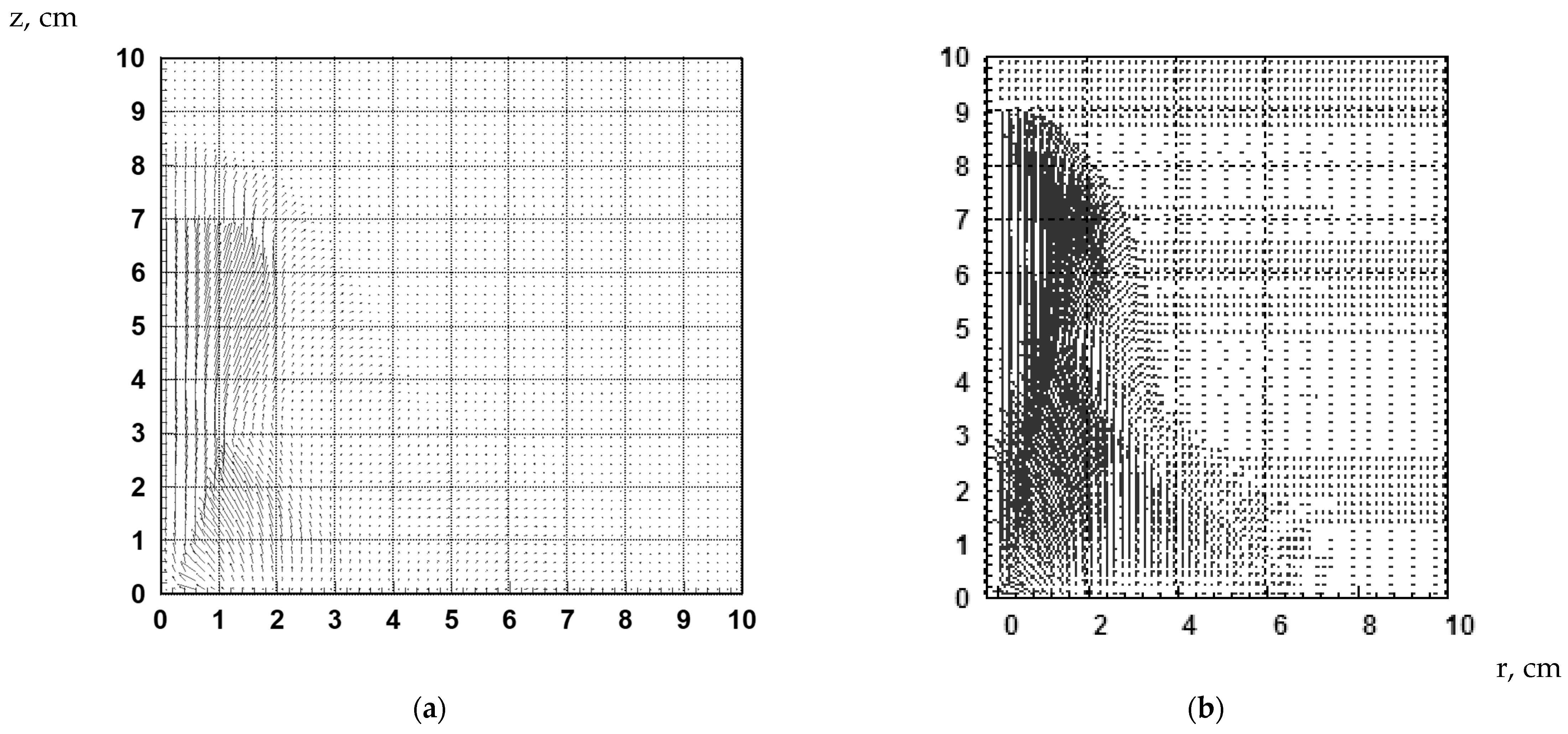
The strong gas dynamic shock wave in the surrounding gas (SWG) propagation velocity in the near-edge zone is higher than the SWG velocity in the peripheral zone. The transient regime has a shock front axial coordinate in the axial region; its value, by the time of the discharge current maximum, is about the size of the magneto plasma compressor midpoint, i.e., z m D t m 2 r 2 . Velocity lines have shown in Figure 2.
Figure 3 consists of the level lines for density and temperature at discharge current J = 353 kA for the magneto plasma compressor with the parameters C = 750 μF, and U 0 = 10 kV, R 1 = 0.8 × 10⁻² m, and R 2 = 5 × 10⁻² m for argon.
Figure 4 contains the level lines for Alfvén velocity (km/s) and velocity modulus (km/s) at current J = 353 kA for the magneto plasma compressor parameters C = 750 μF, and U 0 = 10 kV, R 1 = 0.8 × 10⁻² m, and R 2 = 5 × 10⁻² m for argon.
In the generalized interpolation (according to the results of all calculations), the dependence λ R value on the A m parameter shows that the role of the ohmic energy dissipation mechanism is significant over almost the entire range of discharge power regimes in the magneto plasma compressor and the ambient gas densities.

5. Comparison of the Results of Calculations of MPC Discharges in Gases with Experimental Data

The parameters of the device were the following: C = 30–900 µF, U = 2–200 kV, an argon and air environment, p = 0.01–0.25 MPa.
First of all, we note a satisfactory (5–10%) coincidence with the experiment of electrical parameters (amplitudes, degree of attenuation, and duration of half-periods) of the pulses of discharge current and voltage on the electrodes for all of the energy–power modes studied in the experiment.
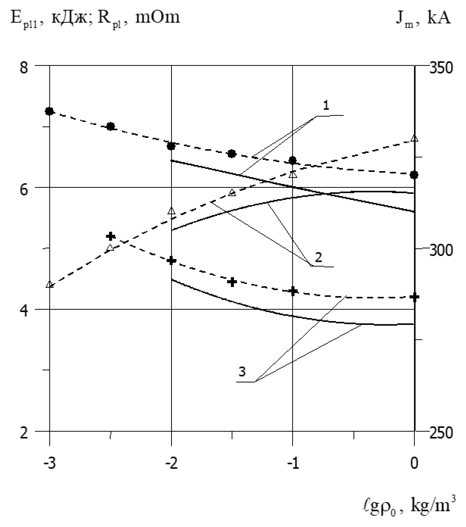
In order to illustrate what has been said, Figure 5 shows the graphical dependences of the experimental [15,16] and calculated basic electrical parameters of the MPC discharge (C = 750 µF, U = 5 kV) on the density of gas (Ar). Here, the energy is supplied to the plasma in first half-cycle of MPC discharge.
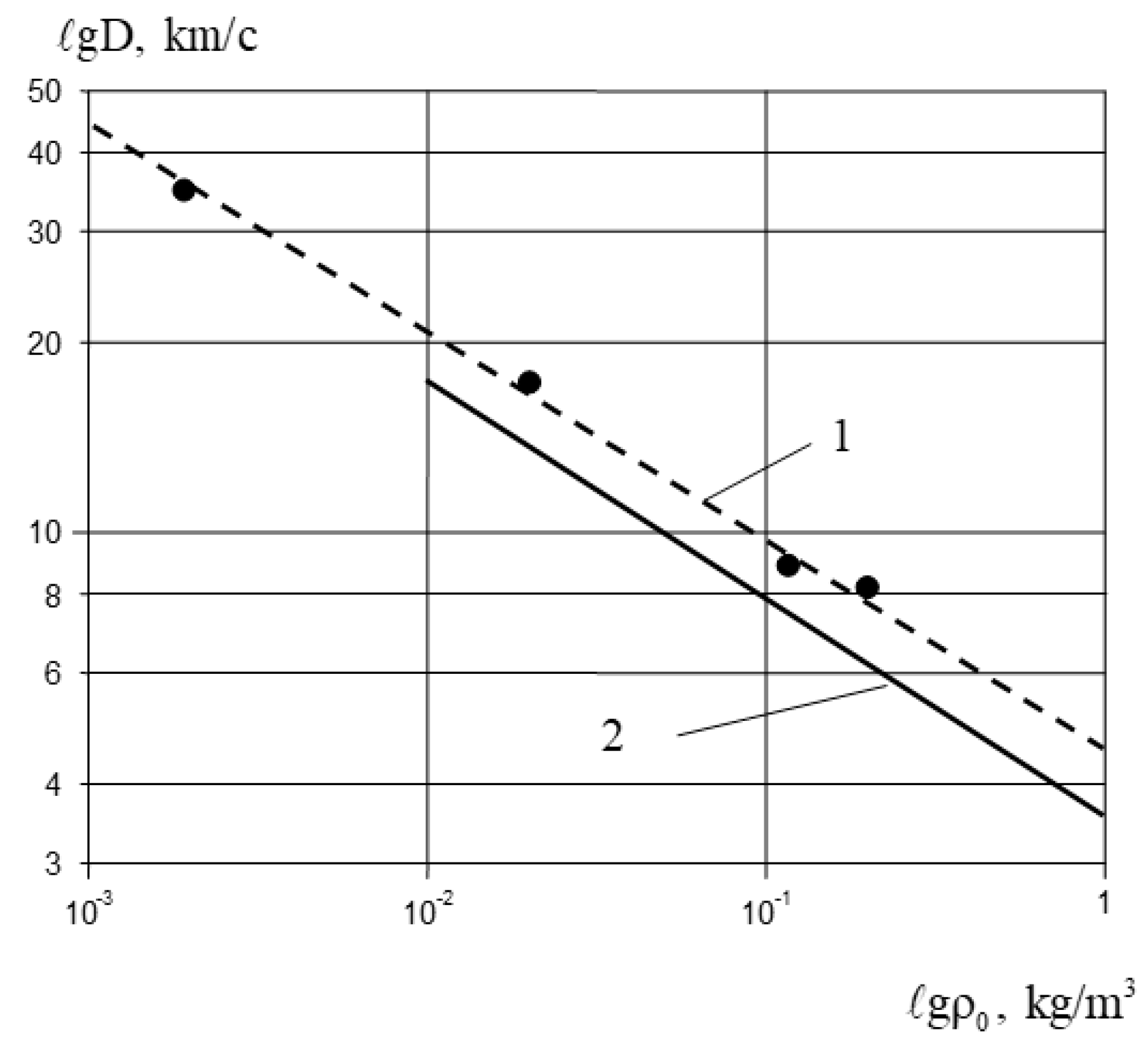
The dynamics of changes in the position of the external boundaries of the discharge over time in all MPC power modes, both in calculations and in experiments, satisfactorily coincide. The dynamics of the changes in the velocity of the head of the shock wave in the gas in the direction of the discharge axis are quantitatively close (as well as in the experiment, there is a movement with acceleration at the phase of growth of the discharge current of the first half-period), and there is a dependence of the average (one half-period) velocity of the shock wave in the gas on the average electrical power, the geometry of the electrodes, the density of the surrounding gas, etc. Thus, in Figure 6, the experimental and calculated graphical dependences of the average velocity of the SW boundary of the MPC discharge on the Ar density are presented. It can be seen that the experiment and calculated results over the entire studied range of characteristics coincide with an accuracy no lower than 20%.
The integral radiative characteristics of MPC discharges are both quantitatively and qualitatively consistent with experimental data [15,16]. Thus, we note that, as in the experiment, the calculations revealed the optimal radiation mode when the integral light output η Σ m ( A m ) is at a maximum. At the same time, the level of the calculated maximum values of light output η Σ m coincides with the experimental values. Also consistent with the experiment is the fact established by calculation that the type of gas has a rather weak effect on the integral radiative efficiency.
The results of calculations of spectral-brightness characteristics of MPC in general satisfactorily coincide with experiments.
The calculated spectral energy distributions of MPC discharge radiation in gases, depending on the gas density ρ 0 , average electrical power P e l 1 , and the type of gas (see Table 2), also correspond to experimental data [15,16].
At the same time, in the visible range, the “half” duration of the radiation pulse is of the same order as the time of the discharge period and more. The maximum brightness temperature MPC, which occur at times close to the maximum power of the power supply, in calculations and experiments approximately coincide with each other for all of the studied power modes.
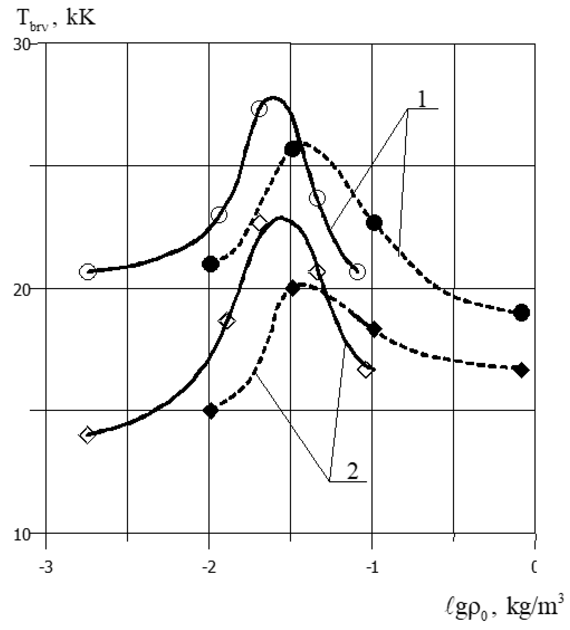
As an example, Figure 7 shows the experimental [15,16] and calculated values of the maximum brightness temperature of the MPC in argon and air, depending on the density of the gas (at fixed C = 750 µF, U = 5 kV) and the specific electrical power (at a fixed ambient density).
The presented results allow us to report a fairly satisfactory ( 20 ÷ 30 % ) correspondence of the experimental and calculated data.

6. Conclusions

Herein, a numerical simulation of plasma dynamic magneto plasma compressor discharge in gases was carried out. A numerical simulation of erosive magneto plasma compressors was carried out, which revealed the complex self-consistent nature of energy transfer processes from storage to plasma; the processes of erosive plasma formation, the dynamics of acceleration, and the interaction of light erosive plasma flows between themselves, as well as the surrounding spatial distributions of plasma parameters for ohmic and transient heating modes, were obtained. From the generalized interpolation (according to the results of all calculations), the dependence value on the parameter shows that the role of the ohmic energy dissipation mechanism is significant over almost the entire range of discharge power modes in the magneto plasma compressors and the ambient gas densities.
Further directions of work on the study of the magneto plasma compressor include:
-
the possibility of adding new force factors (in addition to the forces of inertia and magnetic field) to increase the efficiency of the magneto plasma compressor;
-
establishing the dependence of the main parameters of plasma flows (density, plasma temperature, velocity, energy content) on pressure, type of working gas, and discharge energy;
-
optimization of the MPC design and its power supply system in order to reduce its weight and dimensions and increase efficiency.

Author Contributions

Conceptualization, S.V.R.; software, V.V.K.; validation, V.V.K.; writing—original draft preparation, S.V.R. and V.V.K.; writing—review and editing, S.V.R. and A.Y.V.; project administration, S.V.R. All authors have read and agreed to the published version of the manuscript.

Funding

This research received no external funding.

Institutional Review Board Statement

Not applicable.

Informed Consent Statement

Not applicable.

Data Availability Statement

No new data were created or analyzed in this study. Data sharing is not applicable to this article.

Conflicts of Interest

The authors declare no conflict of interest.

References

  1. Raizer, Y.P. Gas Discharge Physics; Springer: Berlin, Germany, 1991. [Google Scholar]
  2. Stewardson, H.R.; Novac, B.M.; Miran, S.M.; Smith, I.R.; Enache, M.C. A two-stage exploding-foil/plasma erosion opening switch conditioning system. J. Phys. D Appl. Phys. 1997, 30, 1011. [Google Scholar] [CrossRef]
  3. Giovannini, A.Z.; Barendregt, I.; Haslinde, T.; Hubbs, C.; Abhari, R.S. Self-confined plasma in a magneto-plasma compressor and the influence of an externally imposed magnetic field. Plasma Sources Sci. Technol. 2015, 24, 025007. [Google Scholar] [CrossRef]
  4. Brovkin, V.G.; Klimov, A.I.; Mashek, I.C.; Pashchina, A.S.; Ryzazansky, N.M.; Vedenin, P.V. Initiation of the plasma jet of the magneto-plasma compressor by the external plasma source. J. Phys. Conf. Ser. 2021, 2100, 012005. [Google Scholar] [CrossRef]
  5. Zel’dovich, Y.B.; Raizer, Y.P. Physics of Shock Waves and High-Temperature Hydrodynamic Phenomena; Dover: Mineola, NY, USA, 2002. [Google Scholar]
  6. Garkusha, I.E.; Chebotarev, V.V.; Herashchenko, S.S.; Makhlaj, V.A.; Kulik, N.V.; Ladygina, M.S.; Marchenko, A.K.; Petrov, Y.V.; Staltsov, V.V.; Shevchuk, P.V.; et al. Novel test-bed facility for PSI issues in fusion reactor conditions on the base of next generation QSPA plasma accelerator. Nucl. Fusion 2017, 57, 116011. [Google Scholar] [CrossRef]
  7. Grishin, Y.M.; Kozlov, N.P.; Kuzenov, V.V. Singularities of spectral-brightness characteristics of pulsed radiating surface discharges in dense gases. High Temp. 1998, 36, 169–175. [Google Scholar]
  8. Göksel, B.; Mashek, I.C. First Breakthrough for Future Air-Breathing Magneto-Plasma Propulsion Systems. J. Phys. Conf. Ser. 2017, 825, 012005. [Google Scholar] [CrossRef]
  9. Kamrukov, A.S.; Kashnikov, G.N.; Kozlov, N.P.; Kondratenko, M.M.; Lebedev, E.F.; Orlov, V.K.; Ostashev, V.E.; Protasov, Y.S.; Semenov, A.M. Experimental investigation of the effectiveness of the matching of a magneto plasma compressor with an explosive magnetohydrodynamic generator. High Temp. 1984, 22, 313–318. [Google Scholar]
  10. Kuzenov, V.V.; Ryzhkov, S.V. Numerical Simulation of Pulsed Jets of a High-Current Pulsed Surface Discharge. Comput. Therm. Sci. 2021, 13, 45–56. [Google Scholar] [CrossRef]
  11. Kozlov, A.N. Study of MHD dynamo effect at the outlet from plasma accelerator in the presence of longitudinal magnetic field. Contrib. Plasma Phys. 2020, 60, e201900174. [Google Scholar] [CrossRef]
  12. Kuzenov, V.V.; Ryzhkov, S.V. The Qualitative and Quantitative Study of Radiation Sources with a Model Configuration of the Electrode System. Symmetry 2021, 13, 927. [Google Scholar] [CrossRef]
  13. Astashynski, V.M.; Dzahnidze, H.M.; Kostyukevich, E.A.; Kuzmitski, A.M.; Shoronov, P.N.; Shymanski, V.I.; Uglov, V.V. Generation of erosion compression plasma flows in a miniature plasma accelerator and their capability for formation of thin nanostructured coating. High Temp. Mater. Process. 2020, 24, 99–107. [Google Scholar] [CrossRef]
  14. Kuzenov, V.V.; Ryzhkov, S.V.; Varaksin, A.Y. The Adaptive Composite Block-Structured Grid Calculation of the Gas-Dynamic Characteristics of an Aircraft Moving in a Gas Environment. Mathematics 2022, 10, 2130. [Google Scholar] [CrossRef]
  15. Kamrukov, A.S.; Kozlov, N.P.; Protasov, Y.S.; Chuvashev, S.N.; Shchepanyuk, T.S. On the influence of hydrodynamic instabilities on the spectral-brightness characteristics of radiating discharges. Tech. Phys. 1987, 57, 1412–1416. [Google Scholar]
  16. Kamrukov, A.S.; Kozlov, N.P.; Malashchenko, V.A.; Protasov, Y.S. Formation of a plasma focus in a plasma erosion accelerator. III—Radiation properties of the dense plasma focus. Sov. Phys. Tech. Phys. 1977, 22, 967–974. [Google Scholar]
  17. Vedenov, A.A.; Gladush, G.G. Physical Processes in Laser Processing of Materials; Energoatomizdat: Moscow, Russia, 1985. [Google Scholar]
  18. Varaksin, A.Y.; Ryzhkov, S.V. Vortex Flows with Particles and Droplets (A Review). Symmetry 2022, 14, 2016. [Google Scholar] [CrossRef]
  19. Kuzenov, V.V.; Ryzhkov, S.V.; Varaksin, A.Y. Numerical Modeling of Individual Plasma Dynamic Characteristics of a Light-Erosion MPC Discharge in Gases. Appl. Sci. 2022, 12, 3610. [Google Scholar] [CrossRef]
  20. Varaksin, A.Y.; Ryzhkov, S.V. Particle-Laden and Droplet-Laden Two-Phase Flows Past Bodies (A Review). Symmetry 2023, 15, 388. [Google Scholar] [CrossRef]
  21. Varaksin, A.Y.; Ryzhkov, S.V. Turbulence in Two-Phase Flows with Macro-, Micro- and Nanoparticles: A Review. Symmetry 2022, 14, 2433. [Google Scholar] [CrossRef]
  22. Kuzenov, V.V.; Ryzhkov, S.V.; Varaksin, A.Y. Calculation of heat transfer and drag coefficients for aircraft geometric models. Appl. Sci. 2022, 12, 11011. [Google Scholar] [CrossRef]
  23. Grishin, Y.M.; Kozlov, N.P.; Kuzenov, V.V. On the degradation of a shock wave in high-current radiating discharges in gases at atmospheric pressure. Tech. Phys. Lett. 1998, 24, 444–445. [Google Scholar] [CrossRef]
  24. Varaksin, A.Y.; Romash, M.E.; Kopeitsev, V.N. Controlling the behavior of air tornados. High Temp. 2009, 47, 836–842. [Google Scholar] [CrossRef]
  25. Varaksin, A.Y.; Romash, M.E.; Kopeitsev, V.N. Physical simulation of air tornados: Some dimensionless parameters. High Temp. 2011, 49, 310–313. [Google Scholar] [CrossRef]
  26. Dyachenko, V.F.; Imshennik, V.S. Two-dimensional magnetohydrodynamic model for the dense plasma focus of a Z pinch. In Reviews of Plasma Physics; Leontovich, M.A., Ed.; IOP Publishing: Bristol, UK, 1980; Volume 8, pp. 199–299. [Google Scholar]
  27. Kuzenov, V.V.; Ryzhkov, S.V. Estimation of the neutron generation in the combined magneto-inertial fusion scheme. Phys. Scripta 2021, 96, 125613. [Google Scholar] [CrossRef]
  28. Olson, G.L. Efficient solution of multi-dimensional flux-limited nonequilibrium radiation diffusion coupled to material conduction with second-order time discretization. J. Comput. Phys. 2007, 226, 1181. [Google Scholar] [CrossRef]
  29. Braginskii, S.I. Transport processes in plasma. In Reviews of Plasma Physics; Leontovich, M.A.I., Ed.; Consultants Bureau: New York, NY, USA, 1965. [Google Scholar]
  30. Surzhikov, S.T. Computing system for solving radiative gasdynamic problems of entry and re-entry space vehicles. In Proceedings of the 1st International Workshop on Radiation of High Temperature Gases in Atmospheric Entry, Lisbon, Portugal, 8–10 October 2003; Volume ESA-533. pp. 111–118. [Google Scholar]
  31. Kuzenov, V.V.; Ryzhkov, S.V.; Shumaev, V.V. Application of Thomas-Fermi model to evaluation of thermodynamic properties of magnetized plasma. Probl. At. Sci. Technol. 2015, 1, 97–99. [Google Scholar]
  32. Kuzenov, V.V.; Ryzhkov, S.V. Numerical modeling of laser target compression in an external magnetic field. Math. Model. Comput. Simul. 2018, 10, 255–264. [Google Scholar] [CrossRef]
  33. Volkov, K.N.; Emel’yanov, V.N. Modelirovanie Krupnykh Vikhrei v Raschetakh Turbulentnykh Techenii (Simulation of Large Eddies in the Calculations of Turbulent Flows); Fizmatlit: Moscow, Russia, 2008. (In Russian) [Google Scholar]
  34. Kuzenov, V.V.; Kotov, M.A. Analysis of gas dynamic processes and development of a flow model in a shock hypersonic wind tunnel. Vestn. Mosk. Gos. Tekh. Univ. N. E. Baumana Ser. Mashinostr. 2014, 1, 3–25. (In Russian) [Google Scholar]
  35. Kuzenov, V.V. Construction of regular adaptive grids in spatial domains with curved boundaries. Vestn. Mosk. Gos. Tekh. Univ. N. E. Baumana, Ser. Mashinostr. 2008, 1, 3–11. (In Russian) [Google Scholar]
  36. Chetverushkin, B.N. Mathematical Modeling of Problems in the Dynamics of a Radiating Gas; Nauka: Moscow, Russia, 1985. [Google Scholar]
  37. Kuzenov, V.V.; Ryzhkov, S.V. Approximate calculation of convective heat transfer near hypersonic aircraft surface. J. Enhanc. Heat Transf. 2018, 25, 181–193. [Google Scholar] [CrossRef]
  38. Molchanov, A.M. An effective numerical method for simulating chemically and thermally nonequilibrium gas flows. J. Phys. Conf. Ser. 2020, 1683, 022009. [Google Scholar] [CrossRef]
  39. Formalev, V.F.; Degtyarenko, R.A.; Garibyan, B.A.; Kolesnik, S.A. Modeling heat and mass transfer during periodical spraying of a high-temperature heat-resistant coating. High Temp. 2022, 60 (Suppl. 1), S76–S80. [Google Scholar] [CrossRef]
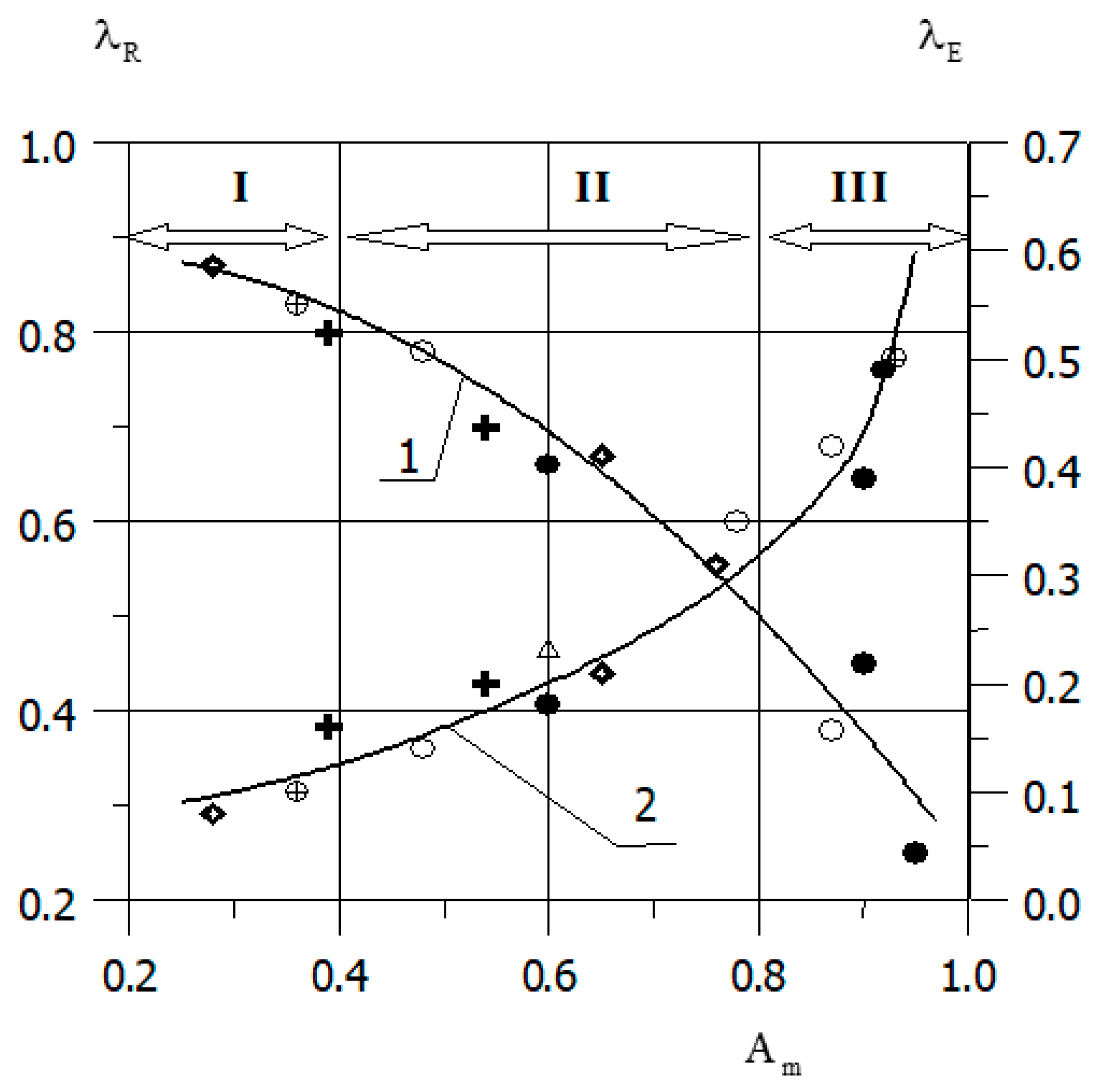
Figure 1. Generalized dependences λ R = R ¯ o m / R ¯ p l (1) and λ E = E ¯ k i n ( t m ) / E ¯ int ( t m ) (2) on parameter A m (the A m range corresponds to Table 1 ). ●, ♦, +, —Calculation; I—region of ohmic mode parameters; II—region of transition mode parameters; III—region of plasma dynamic mode parameters.
Applsci 13 05538 g001
Figure 2. Vector velocity field for the magneto plasma compressor ( C = 750 µF) in argon: (a) U 0 = 5 kV, P = 0.01 MPa, t = 15.3 µs; (b) U 0 = 10 kV, P = 0.001 MPa, t = 6.5 µs.
Applsci 13 05538 g002
Figure 3. Density (kg/m3) level lines (a), temperature (kK) (b) for argon, pressure 103 Pa, A m = 0.85: SWP—shock wave in the plasma, CB(PG)—contact boundary, separating the plasma and gas, CB(MD)—contact boundary between metal and dielectric, RW—radiation wave.
Applsci 13 05538 g003
Figure 4. The Alfvén velocity lines (a), and the velocity modulus (b) at time t = 6.5 microseconds for the magneto plasma compressor (internal radius R 1 = 0.8 × 10⁻² m, and external radius R 2 = 5 × 10⁻² m) with characteristics C = 750 μF, U 0 = 10 kV for Ar.
Applsci 13 05538 g004
Figure 5. Electrical parameters of MPC discharge ( C = 750 μF, U 0 = 5 kV) depending on gas density (argon): 1— E p l 1 ; 2— J m ; 3— R p l , the dotted line corresponds to the experiments [15,16]; the solid line corresponds to the calculation.
Applsci 13 05538 g005
Figure 6. Velocity of the SW boundary of discharge along the MPC-discharge axis (C = 750 µF, U = 5 kV), depending on the density of the surrounding gas (argon): 1—experimental data [15,16]; 2—calculation.
Applsci 13 05538 g006
Figure 7. Influence of the gas type and density on brightness temperature in UV region of the spectrum ( Δ λ = 186 ÷ 200   HM ) of MPC discharge with C = 750 µF, U = 5 kV: 1—Ar; 2—air (○, ◊—experiments [15,16]; ●, ♦—calculation).
Applsci 13 05538 g007
Table 1. Mode parameter A m dependent on gas pressure p 0 and parameters of the power storage magneto plasma compressor discharge.
p 0 , MPa C , μF U 0 , kV W 0 , kJ A m
10−328.6101.430.6
3012.90.9
5035.70.93
75021.50.48
59.370.78
1037.50.91
10−228.6101.430.3
3012.90.65
5035.70.76
75059.370.6
1037.50.85
10−128.63012.90.36
2005710.95
75021.50.25
59.370.4
1037.50.54
Table 2. Relative distribution of radiation energy in the MPC discharge spectrum (%).
GasArgonAir
Spectral
Interval, eV
MPC Parameters
C = 750 µF, U = 5 kVC = 750 µF, U = 10 kVC = 750 µF, U = 10 kV
P = 10−1 atm,
Am = 0.6
P = 10−2 atm,
Am = 0.8
P = 10−2 atm,
Am = 0.85
P = 10−2 atm,
Am = 0.85
0.1 ÷ 3.1420202040
3.14 ÷ 5.9830201550
5.98 ÷ 11.6250403510
>11.622030
Disclaimer/Publisher’s Note: The statements, opinions and data contained in all publications are solely those of the individual author(s) and contributor(s) and not of MDPI and/or the editor(s). MDPI and/or the editor(s) disclaim responsibility for any injury to people or property resulting from any ideas, methods, instructions or products referred to in the content.