Article

Understanding the Mechanism of Strong Mining Tremors near the Goaf Area of Longwall Mining: A Case Study

1
School of Mines, China University of Mining & Technology, Xuzhou 221116, China
2
Jiangsu Engineering Laboratory of Mine Earthquake Monitoring and Prevention, China University of Mining & Technology, Xuzhou 221116, China
3
Xuzhou Wushuo Information Co., Ltd., Xuzhou 221116, China
4
State Key Laboratory of Coal Resource and Safe Mining, China University of Mining & Technology, Xuzhou 221116, China
*
Author to whom correspondence should be addressed.
Appl. Sci. 2023, 13(9), 5364; https://doi.org/10.3390/app13095364
Submission received: 17 April 2023 / Revised: 21 April 2023 / Accepted: 24 April 2023 / Published: 25 April 2023

Abstract

:
Strong mining tremors (SMTs) frequently occur in super-thick strata near the goaf when mining. Since 2021, there have been three consecutive SMTs with magnitude greater than 2.0 in longwall 1208 of the Shilawusu Coal Mine. These SMTs caused mine production to be suspended for more than 290 days and affected over 100 households located on the shaking ground, and seriously threatened the safety of underground workers and restricted production capacity. Therefore, it is essential to investigate the occurrence mechanism of SMTs in super-thick strata goaf mining in order to understand the phenomenon, how the disaster of mining tremors occurs, and the prevention and control of mining tremor disasters. In this study, field observation, numerical analysis, and theoretical calculation were used to study the occurrence mechanism of three SMTs in the Shilawusu Coal Mine. The results show that the super-thick strata fracture induced by the SMTs is generally higher by one to three orders of magnitude in some of the source mechanical parameters compared to other mining tremors, and so is more likely to cause ground shaking. Field observations revealed that before and after the occurrence of SMTs, the maximum surface subsidence suddenly increased by about 0.1 m and showed a “stepped” increase, and the super-thick strata began to experience fractures. The following theoretical mechanics model of super-thick strata was established: at the goaf stage of mining, with the increase in the area of the hanging roof, the super-thick strata will experience initial and periodic fractures, which can easily induce SMTs. The relative moment tensor inversion method was used to calculate the source mechanism of SMTs, which was found to be caused by the tensile rupture resulting from the initial and periodic ruptures of super-thick strata, in addition to the shear rupture generated by the adjustment of unstable strata structures. As the mining continues on the longwall face, there is still a possibility of SMT occurrence. This paper provides some insights into the mechanism and prevention of SMT in underground coal mines.

1. Introduction

A mining tremor is a kind of earthquake induced by mining activity [1]. It is an inevitable dynamic phenomenon in deep coal mining which threatens the safety of mine production and affects the normal life of mining residents. The overlying strata of the deep mine in the Ordos mining area are super-thick strata [2]. Fracturing and slipping of the super-thick strata may cause secondary disasters (such as mining tremors, rock bursts, and landslides) during deep coal mining [3]. Since 2021, there have been six strong mining tremors (SMTs) of magnitude greater than 2.0 in the Ordos mining area, which seriously restricted the normal connection of mines and deepened the panic of mining residents regarding the phenomenon of SMTs. SMTs have evolved from a mine safety problem into a public safety problem [4].
The super-thick strata is generally characterized by high thickness and high rock integrity. In the process of deep mining, large overhanging roofs can be formed, resulting in concentration of stress in the roadway surrounding rock [5,6]. Therefore, the occurrence mechanism of SMTs induced by deep coal mining with super-thick strata is quite complicated. Liu et al. [7] found that the increase in local stress caused by super-thick strata is the main cause of SMTs. Xu et al. [8] studied the accumulation characteristics of elastic properties in the bending compression process of ultra-thick rock strata and found that the crushing of super-thick strata is the energy source of SMTs. Zhang et al. [9] revealed that a large amount of elastic energy released by SMTs induced by fracture of super-thick strata may cause severe ground shaking. Xie et al. [10] explained that the macro-stress field and energy field would change dynamically due to the fracture of super-thick strata induced by deep coal mining, thus triggering SMT. Guo et al. [11] believe that SMTs can be induced when the critical failure strength of super-thick strata is exceeded under the action of static and dynamic loads. Lu et al. [12] found that SMTs were easily induced by the dynamic stress caused by the fracture of super-thick strata in the roof caving zone. Konicek et al. [13] summarized the factors that trigger SMTs, including rock properties and mining conditions, and proposed that the fracture of super-thick strata under the influence of mining conditions promoted the occurrence of SMTs.
SMTs are the result of the dynamic adjustment of macro energy fields and stress fields in super-thick strata. This process is relatively slow, but it is the key to revealing the occurrence mechanism of SMTs. Zhang et al. [14] established an energy index, EI, to analyze the characteristics of energy change; their results showed that the energy change presented a bimodal distribution before the occurrence of SMTs. Sazid et al. [15,16] believe that roof deformation occurs before the SMT and the elastic energy accumulates quickly, and further analyzed the influence of SMTs on surface stability. Wang et al. [17] studied the evolution characteristics of mine vibration energy and found that the remaining part of the elastic strain energy is the source of mine vibration energy. Dou et al. [18] analyzed the distribution law of mining stress fields based on wave velocity CT inversion, and found that SMTs occurred after the stress increased sharply. Yang et al. [19] tested the stress states of different strata and found that the stress states of sub-horizontal strata changed dramatically before the occurrence of SMTs. He et al. [20] elaborated that the stress concentration in super-thick strata would lead to the accumulation of elastic energy, which provides the basis for triggering SMTs.
The above research indicates that the fracture and movement of super-thick strata play an important role in the occurrence of SMTs in deep mining. The evolution characteristics of the stress field and energy field before the occurrence of SMTs are systematically studied, which provides great inspiration for the further investigation of the occurrence mechanism of SMTs. In order to explain the occurrence mechanism of SMTs triggered by goaf mining with super-thick strata in the Ordos mining area, the characteristics of fracture movement of super-thick strata should be explored [21], which greatly depends on real-time observation of strata separation failure in super-thick strata, and analysis of the changing characteristics of internal fracture modes of different strata.
This study was based on the SMTs induced by goaf mining in the longwall (LW) 1208 of Shilawusu Coal Mine, Ordos mining area. The techniques of strata separation detection and strata deformation monitoring were used. The temporal and spatial relationship between the fracture movement of the super-thick strata and the SMTs was established in this study. Based on the Reissner theory of thick plates, the fracture movement law of super-thick strata during goaf mining was analyzed. The focal mechanism of SMTs was calculated by the relative moment tensor inversion method. The patterns of evolution of fracture mode of the source of mining tremors triggered by step fracture of strata under the super-thick strata was analyzed. This analysis reveals the mechanism of the occurrence of SMTs triggered by the goaf mining with the super-thick strata.

2. Geological Setting and Data

2.1. Formation and Mining Condition

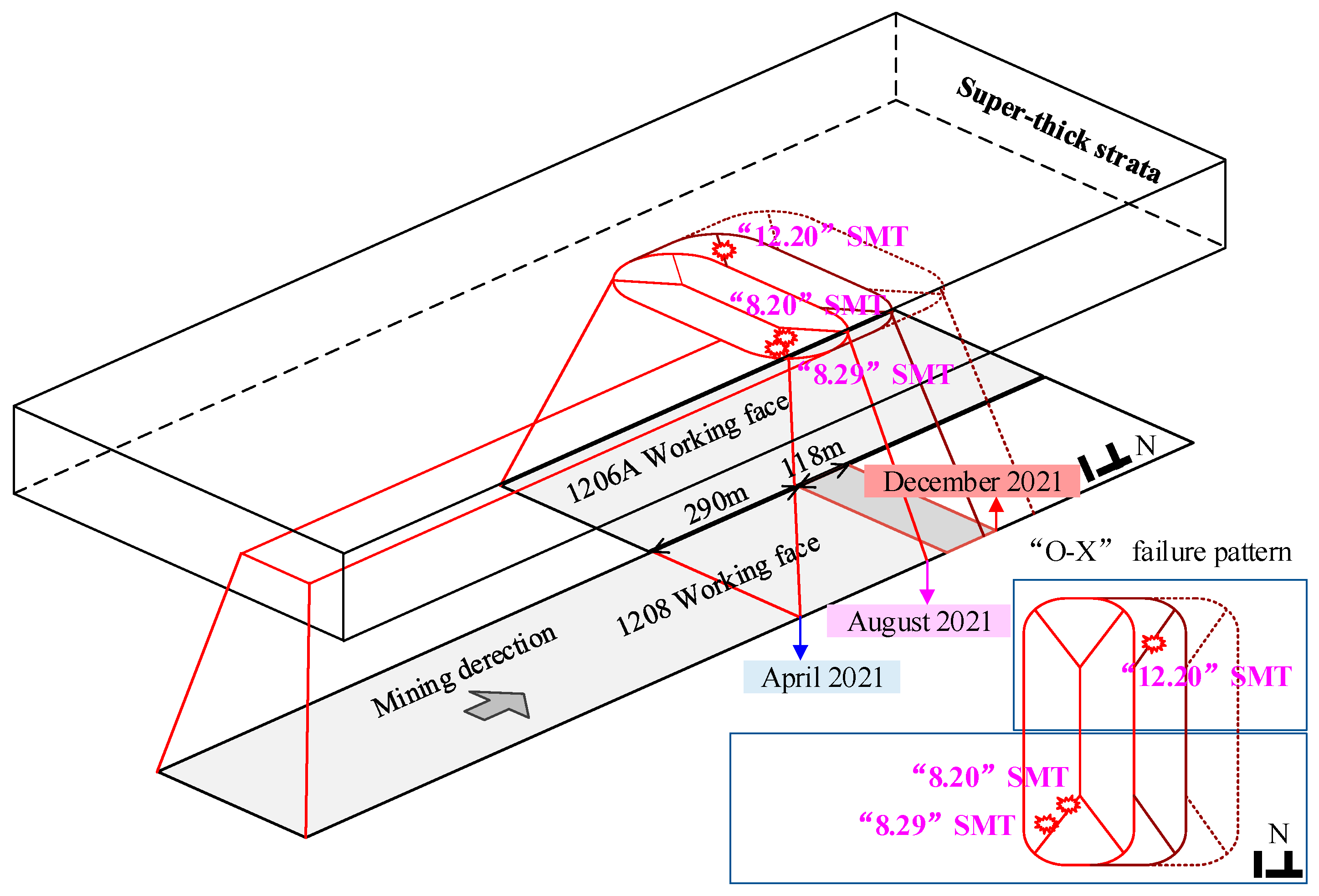
LW 1208 is arranged on the east side of LW 1206A, located in the south wing of the 12th panel area of the mine. The main mining is of 2-2 coal with a thickness of 8.51–9.51 m and an average of 9.08 m. The geological conditions of the coal seam are simple, and the mining depth is 640–711 m. As shown in Figure 1, the LW 1206A is to the north of LW 1208. The stopping lines of the two LWs are aligned and the length of the open cut of both faces is 290 m, and 5 m narrow coal pillars are set. LW 1206A, with a strike length of 1120 m, was completed in October 2019. In May 2021, LW 1208 entered into mining near the goaf. By 20 December 2021, 2509 m had been mined. The stopping location is 398.2 m above the front of the 1206A open-off cut, with 734.15 m remaining.
Several microseismic sensors are located in LW 1208, which can record the waveform information of mining tremors induced in LW 1208 in real time. Three detection holes are placed in the face to detect the separation of strata as the face is mined. The line of strata movement is used to monitor surface subsidence characteristics.
SMTs occurred on 20 August 2021, 29 August 2021, and 20 December 2021 in the goaf mining phase of LW 1208, causing ground tremors. For simplicity, SMTs are named after their date of occurrence, such as “8.20” SMT. The basic information on the SMTs is briefly described in Table 1.
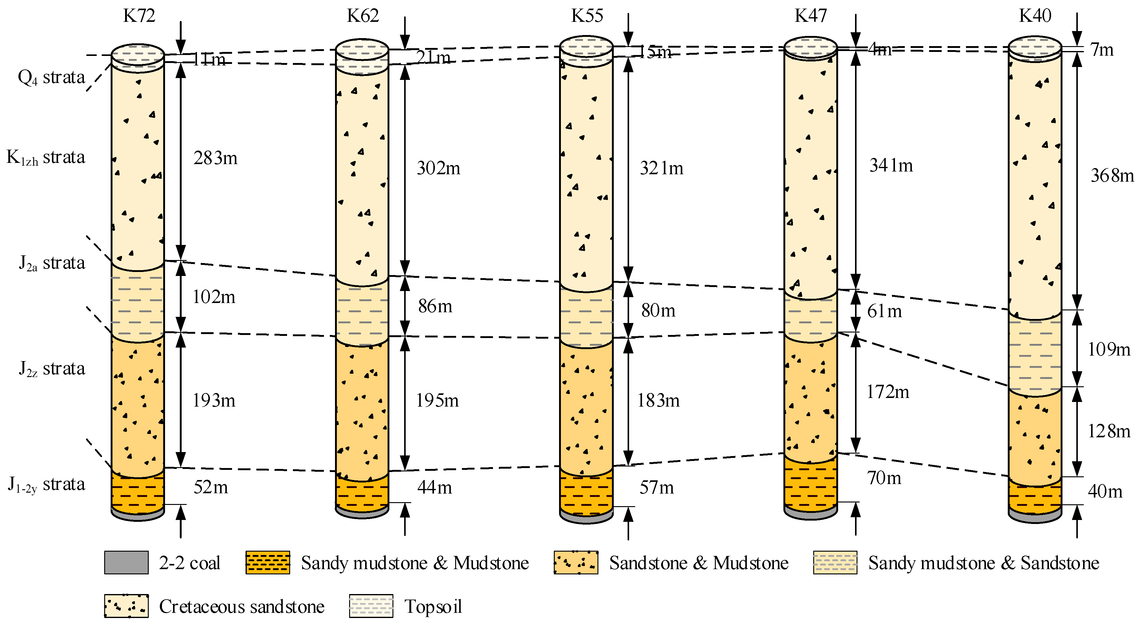
According to the geological borehole information, the overlying strata structure on the working surface of 1208 can be drawn (seen in Figure 2). The Lower Cretaceous Zhidan Group consists of several thick sandstones, while the middle Jurassic Anding and Zhiluo formations are composed of sandstone, sandy mudstone, and interbedded mudstone. The Middle Yan’an Formation of the Jurassic system is a coal-bearing layer, and the part of the layers from the coal seam to the Zhiluo Formation are mainly sandy mudstone and mudstone.
The thickness of the Cretaceous super-thick strata is about 300 m, and the rupture movement of the super-thick strata can cause dynamic disasters such as SMTs and rock bursts during mining. In addition, due to the thin surface soil thickness of LW 1208, the attenuation of the seismic wave is slow after the SMT induced by the fracture movement of the super-thick Cretaceous strata, which easily causes ground tremors.

2.2. Characteristics of Mining Tremors

2.2.1. Spatial Distribution of Mining Tremors

Three SMTs occurred in LW 1208 of Shilawusu Coal Mine, all under the condition of goaf mining. The change of mining conditions of LW 1208 was the main reason for the occurrence of SMTs. According to the different mining conditions of LW 1208, the goaf mining area was divided into areas Ⅰ, Ⅱ, Ⅲ, and Ⅳ, and the mining push times were September~December 2020, January~April 2021, May~August 2021, and September~December 2021, respectively. Areas Ⅰ and Ⅱ correspond to solid coal mining of LW 1208. The area of LW 1208 corresponding to areas Ⅲ and Ⅳ enters into near-goaf mining.
Figure 3 shows the spatial distribution of mining tremors before and after near-goaf mining, as well as the number and energy proportion of mining tremors in each energy interval. The microseismic events in area Ⅰ are characterized by a source energy of less than 104 J with relatively dispersed distribution. LW 1208 continues to advance towards the goaf, which is called region Ⅱ. The number of mining tremors with an energy class of 104–105 J increased from 56 to 71 times compared to region Ⅰ, and a mining tremor with an energy class of over 105 J occurred near the goaf. At the stage of solid coal mining in LW 1208, the source of mining tremors was mainly located in the range of 100 m rock strata above the 2-2 coal seam, namely, the J1-2y formation.
Entering the stage of mining near the goaf, the number of mining tremors of all energy levels increased significantly. In particular, the number of mining tremors exceeding 105 J in area Ⅲ was twice that in area Ⅱ, and in area Ⅳ was the same as in area Ⅱ. These included the “8.20”, “8.29”, and “12.20” SMTs which caused ground shaking. The source of the SMTs is located in the K1zh formation. Prior to the occurrence of the SMT, mining tremors occurred frequently in the strata below K1zh, and the source elevation gradually increased and approached the K1zh formation. The vertical distribution of mining tremors from J2Z to K1zh is approximately triangular.
To summarize, the goaf area increased at the stage of goaf stopping on LW 1208, which leads to the step by step upward strata fracture distribution, and strata fracture often induces mining tremors. Finally, the K1zh fracture induced the “8.20”, “8.29” and “12.20” SMTs.

2.2.2. Distribution Features of Source Mechanical Parameters

The source mechanical parameters (SMPs) with different physical meanings can be divided into three categories: (1) scalar seismic moment ( M 0 ) and radiated energy characterize burst strength; (2) source radius ( r c ) and apparent volume ( v a ) characterize disturbance scale; and (3) stress drop ( Δ σ ) and apparent stress ( σ a p p ) characterize stress adjustment. The detailed physical meanings and formulas can be found by referring to the literature [22].
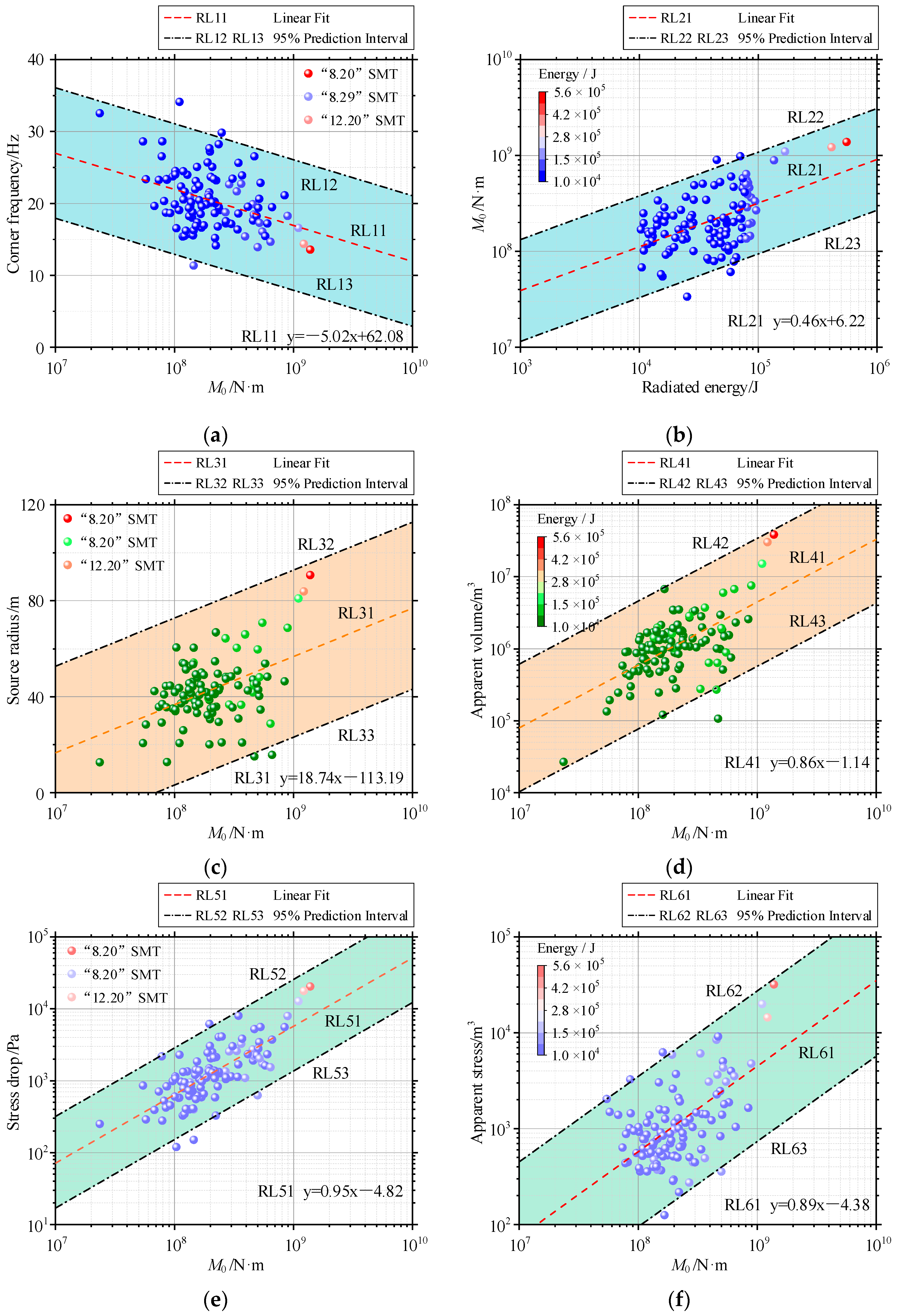
Typical SMTs can be further distinguished by inverting the relationship between the SMPs and analyzing the difference between the SMPs of mining tremors. Figure 4 shows the correlation between the SMPs.
Unlike other mining tremors, the seismic moment of SMTs exceeds 109 N·m, indicating that the burst strength of SMTs is the largest (seen in Figure 4). Figure 4a shows a negative correlation between seismic moment and corner frequency. When M0 exceeds 109 N·m, the corner frequency fc decreases to 10–20 Hz, indicating that it has more abundant low frequency components. The source parameters of Es, rc, va, ∆σ and σapp basically show an obvious linear increase with the increase in M0. The source parameter of rc is close to 100 m, and va is more than 107 m3, i.e., the disturbance scale of the SMTs is the most extensive. The source parameters of ∆σ and σapp both exceed 104 Pa, indicating that the stress change at the source is the largest, leading to the most obvious burst effect before and after the SMT.

3. Law of Strata Fracture Movement

3.1. Observation of Strata Separation

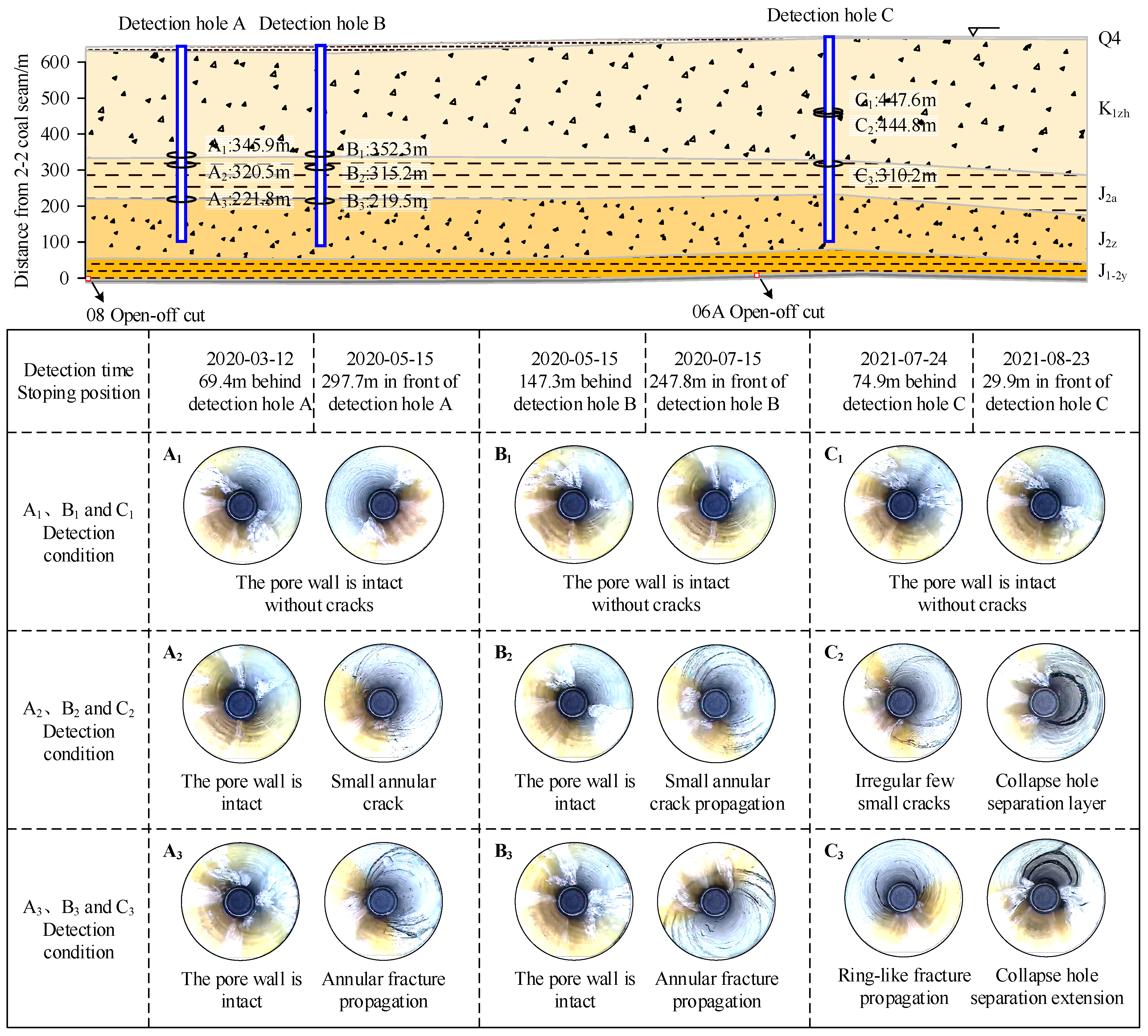
As shown in Figure 5, three detection holes A, B, and C were used to monitor the roof fracturing of the 1208 face during mining. The layout information of detection positions can be seen in Table 2. The observation ranges of the three detection holes A, B, and C are located in the Q4 series to J2z series of coal measure strata from the surface down, respectively.
In the mining process of LW 1208, three detection positions were selected each in detection holes A, B, and C, and repeated exploration was performed to obtain formation separation information. Separation detection was performed before and after the stopping position of LW 1208 was located at the detection hole. Table 2 shows the detection positions and dates of the three detection holes.
From Figure 5, the detection results of A1 (B1) show that the pore wall remains intact and smooth without any cracks, which indicates that the crack development height is limited and does not reach the K1zh formation about 320 m away from the coal seam during the solid coal mining stage of LW 1208. A2 (B2) detection results show that when the stopping position of LW 1208 is behind the detection hole, the hole wall condition is consistent with that of A1 (B1) detection results. When the stopping position of LW 1208 is in front of the detection hole, small cracks begin to appear in the hole wall, and the cracks are similar to rings, with fewer cracks and no developed width.
The detection results of A3 (B3), located at the junction of J2a and J2z layers, show that the stopping position of LW 1208 is in front of the detection hole, the cracks in the pore wall are distributed in a ring, and the width of the cracks is extended, but they do not develop into collapse and separation.
In summary, we could find that the detection results of detection hole C are significantly different from those of detection hole A and B. According to the C2 detection results, before the occurrence of SMT, a small number of irregular cracks appeared in the pore wall, and the number of cracks was large, but the crack width was small and did not expand. Additionally, after the SMT, large annular cracks appear in the pore wall, crack depth and width expand, and the hole collapse phenomenon is more serious. It can be seen from the C3 detection results that before the occurrence of the SMT, the cracks of the pore wall are approximately annular and the number of cracks is small. However, after the occurrence of SMT, the water in the hole is sprayed, the breakage is serious, the block is dropped, and there is a large separation between layers.
After the mining condition of LW 1208 changes from solid coal mining to goaf mining, the development height of cracks extends from the J2a strata to K1zh strata. This finally leads to the occurrence of an SMT, which indicates that the fracture movement of super-thick stratum plays an important role in inducing SMT.

3.2. Monitoring of Strata Deformation

In the mining process, the increase in goaf area can cause large-scale surface subsidence and even cause secondary disasters such as collapse. Therefore, a number of strata movement lines are arranged on the surface of the 12-panel area of the mine to monitor the change in surface settlement caused by mining in LW 1208 (seen in Figure 6).
As of 26 April 2021, LW 1208 is in the solid coal mining stage, the evolution of surface subsidence is shown in Figure 6a. It can be concluded that the maximum surface settlement is small, about 0.23 m. The continuous advance of LW 1208 does not cause a significant change in the maximum surface settlement. Under current mining conditions, the strata movement within LW 1208 has tended to be stable.
As seen in Figure 6b, the maximum surface settlement increases significantly near the goaf mining compared to the solid coal mining stage. Among them, the transition area of solid coal from the face to the goaf is always the first to settle and reaches the maximum amount of settlement, and the settlement rate increases significantly with gradual mining.
In summary, after the mining condition of LW 1208 changed from solid coal mining to goaf mining, the strata structure became unstable, and strata movement could easily induce an SMT, such as the “8.20” SMT.
After the occurrence of the SMT, the surface settlement again increased significantly, indicating that the strata structure is again unstable under the effect of the SMT disturbance, resulting in the rapid surface settlement. Strata structure adjustment also easily induces SMTs, such as the “8.29” SMT. The strata structure is extremely unstable after two SMTs, with LW 1208 mining and super-thick strata fracturing again leading to the occurrence of “12.20” SMT.
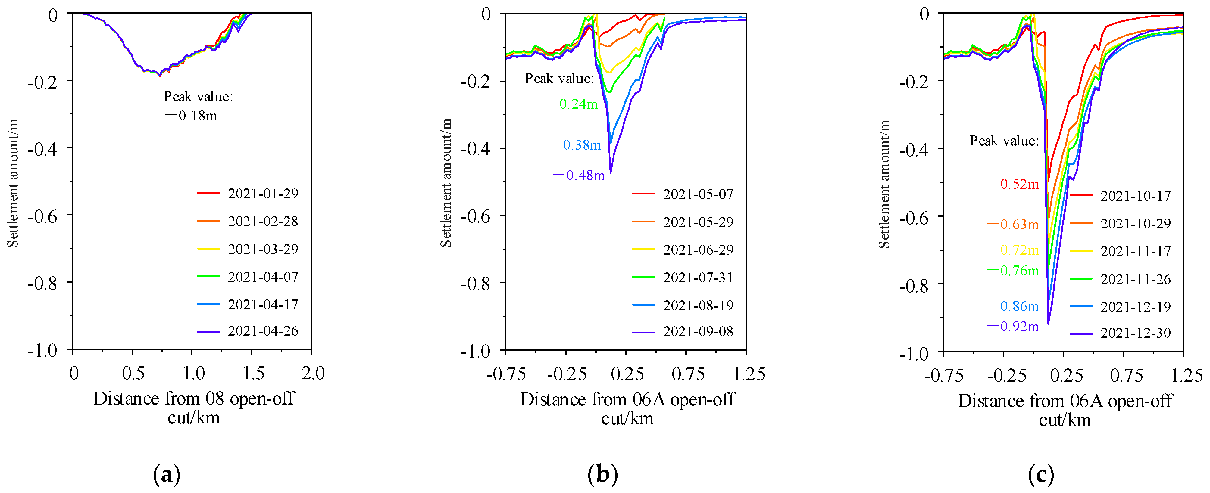
Similar to Figure 6a, the surface settlement is basically unchanged along the strike direction of LW 1208, reflecting that the strata structure has reached a stable state (seen in Figure 7a).
As seen in Figure 7b, the maximum surface settlement reached 0.24 m as LW 1208 entered the goaf mining stage, which exceeded the maximum surface settlement in the solid coal mining stage. On 31 July 2021, the day before the “8.20” SMT, the maximum surface settlement rapidly increased from 0.24 m to 0.38 m. The results show that the super-thick strata are bent and subsided at the goaf mining stage, accumulating a large amount of elastic energy.
The “8.20” SMT caused the unstable movement of the super-thick strata and induced the “8.29” SMT. The maximum surface settlement increased rapidly to 0.48 m. Similarly, before and after the “12.20” SMT, the maximum surface settlement showed a two-stage “stepped” increasing trend (seen in Figure 7c).
Combined with the surface separation detection results, it was found that, the period before the super-thick strata fracture movement induced SMT was always accompanied by rapid subsidence of the stratigraphic structure and rapid accumulation of elasticity, which corresponds to the rise of the first stage of surface settlement. A large amount of elastic energy is released instantaneously after the occurrence of an SMT. Under the disturbance of the elastic wave released by SMT, the super-thick layers become unstable, resulting in the rapid surface settlement again, which corresponds to the second stage of rising surface settlement. Similarly, this process can easily trigger SMTs.

3.3. Theoretical Analysis of Strata Fracture Movement

In order to further analyze the fracture motion of super-thick layers and its temporal and spatial correlation with the occurrence of SMTs, the characteristics of the fracture motion of super-thick layers are here theoretically analyzed.
At present, the “plate” and “beam” theories are used to study the stability of the roof. For the Shilawusu Coal Mine with its super-thick strata structure, it is of more significance to analyze the fracture motion law of super-thick strata by the “plate” theory. With the “plate” theory, according to the score of plate width and thickness, thin plates and thick plates can be distinguished by the following formula [23]:
( 1 100 1 80 ) h b ( 1 8 1 5 ) thin   plate ( 1 8 1 5 ) < h b thick   plate
where h is the thickness of the super-thick strata and b is the width of LW 1208 and LW 1206A.
The incline length of LW 1208 increases to 585 m after the goaf mining stage, where total thickness of the super-thick strata is about 300 m. The width–thickness ratio of the super-thick strata is 300/585 ≈ 1/2, which belongs to the thick category. Therefore, the thick plate correlation theory was used to solve the fracturing and instability conditions of the super-thick roof in LW 1208.
In summary, the theoretical mechanical model of the super-thick strata at the goaf mining stage is shown in Figure 8 [24]. Reissner’s theory of thick plates [25] was applied to analyze the fracture movement characteristics of super-thick strata.
According to Figure 8b, based on the assumption of plane geometric similarity, the basic equation of the mechanical model of thick plates with super-thick strata can be obtained:
{ D Δ Δ ω = q 2 μ 10 ( 1 μ ) h 2 Δ q h 2 10 Δ Q x Q x = D x Δ ω + h 2 10 ( 1 μ ) q x h 2 10 Δ Q y Q y = D y Δ ω + h 2 10 ( 1 μ ) q y
where ω is vertical deflection, q is overburden load, μ is Poisson’s ratio, Qx and Qy are shear forces, D is bending stiffness, D = E h 3 12 ( 1 μ 2 ) , E is Young’s modulus, and h is the thickness of the super-thick strata.
As shown in Figure 8c, based on the boundary conditions before the initial fracture of the super-thick strata, the bending moment of the super-thick strata at x = a/2 and y = b/2 reaches the maximum value Mmax [24]:
M max = 0.96 q b 4 λ c 1 2 ( 7.84 μ + 2.55 I 2 h 2 + 3.49 μ I 2 h 2 + 1.43 μ b 2 a 2 ) + q h 2 I 4
where λc1 is the function determined by the deep beam function, and I1 and I2 are parameters related to μ, I 1 = 1 5 ( 1 μ ) , I 4 = μ 10 ( 1 μ ) .
The maximum tensile stress σmax exists on the lower surface of the super-thick strata [26]:
σ max = 12 M max h 3 Z = 12 M max h 3 h 2 = 6 M max h 2
When the ultimate tensile strength σs and maximum tensile stress σmax of the super-thick strata are σs = σmax = 6Mmax/h2, the initial failure of super-thick strata is achieved.
Combined with Equations (3) and (4), the initial failure criterion of the super-thick strata is obtained as follows:
σ s = 4.14 q b 4 λ c 1 2 ( 7.84 μ h 2 + 2.55 I 2 h 2 + 3.49 μ I 2 + 1.43 μ b 2 a 2 h 2 ) + 6 q I 4
It can be seen that the fracture thickness h, the width of LW b, the overburden load q, and the tensile strength σs are the critical factors for the initial fracture of the super-thick strata. According to the separation detection results, h ≈ 100 m. Considering that the fracture angle of the super-thick strata is 77°, b = 447 m, q = 1.25 MPa, and σs = 2.62 MPa. Substituting this into Equation (5) gives a = 307.7 m, which is the initial fracturing stage of the super-thick strata. At this point, the stopping location is 289.9 m away from the 1206A open-off cut. The theoretical calculation results are consistent with the actual mining conditions and the separation detection results, which proves that the “8.20” SMT was induced by the initial fracture of the super-thick strata.
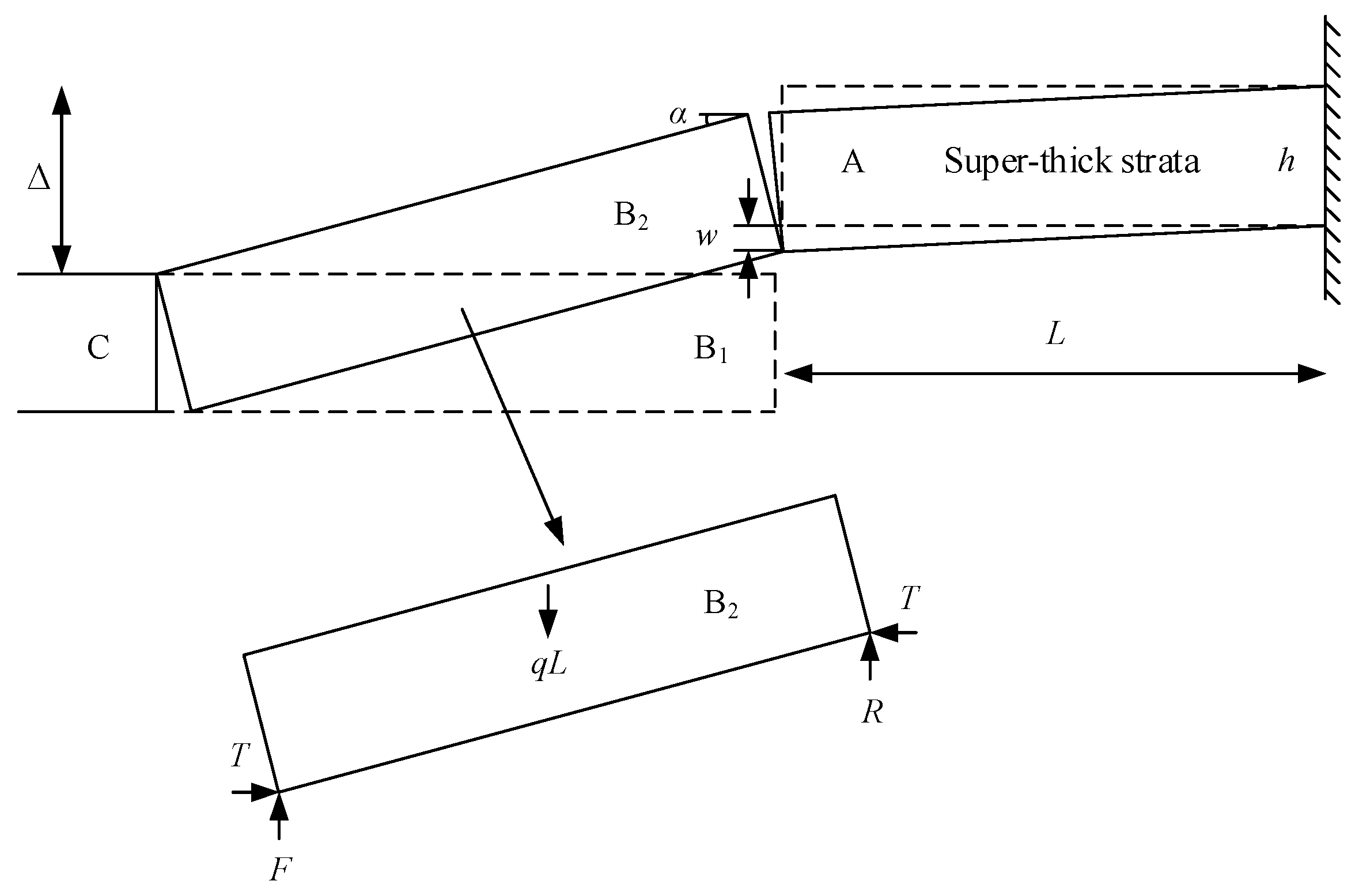
After the initial fracture of the super-thick strata, the mechanical structure was formed as shown in Figure 9.
Based on the critical layer theory, the periodicity fracture step of super-thick strata can be expressed as [27]:
L = h σ s / 3 q
By substituting the relevant parameters, L = 120.4 m is obtained, where the 1208 face advances 118.3 m from 20 August 2021 to 20 December 2021. It can be inferred that the “12.20” SMT was induced by the periodic fracture of the super-thick strata.
In summary, the law of fracture migration of the super-thick strata and its temporal and spatial relationship with the SMTs are shown in Figure 9. the law of fracture migration of the super-thick strata and its temporal and spatial relationship to the SMTs are shown in Figure 10.

4. Rupture Mechanism of Strong Mining Tremors

4.1. Relative Moment Tensor Inversion

4.1.1. Principle of Inversion

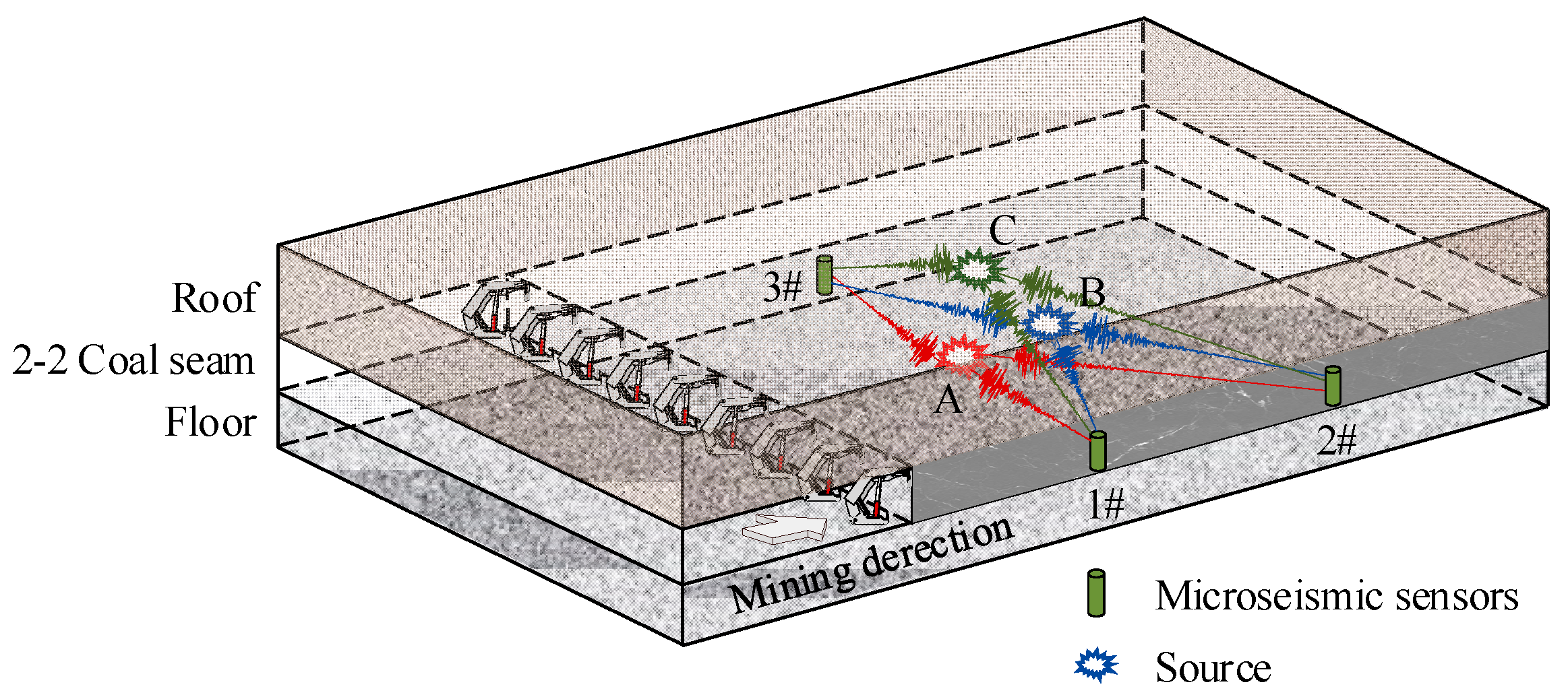
The above studies show that the energy source of the SMT is the fracturing movement of the super-thick strata [28]. In order to further reveal the occurrence mechanism of SMT induced by goaf mining with super-thick strata, the evolution characteristics of the source rupture-type of mining tremors was analyzed based on the relative moment tensor inversion method [29,30]. The method was proposed by Dahm [31], and its main advantage is that Green’s function is transformed by the theory of ray propagation of vibration waves, which greatly reduces the inversion error caused by the anisotropy of the propagation medium.
Figure 11 depicts the principle of the inversion method. Sources A, B, and C are regarded as target source groups; the Green’s function G of the medium from each source to the same sensor propagation path is approximately the same, i.e., GA ≈ GB ≈ GC.
Furthermore, Green’s function G can be simplified to be composed of a weight part a k r q and a linear part I q k n under the restriction of the ray theory [31]. The p-th source involved in constructing the matrix is detected by the q-th sensor and the k-th phase is located at u in the direction n, which can be expressed as:
u p q k n = I q k n r = 1 6 m r p a q k r
where, mrp is the linear part of the moment tensor M; aqkr represents the radiation pattern part of the source, which can be divided into P, SH, and SV; r (r = 1, 2, …, 6) are the six principal axes of M [32]. By constructing the inversion matrix, the linear part I q k n in Equation (5) can be eliminated, and the matrix G is constructed by taking the sensors as the object:
( 0 1 0 2 0 3 0 m 1 0 m 1 ) = ( G 1 G 2 G 3 G q 1 G q 1 ) ( S 1 S 2 S 3 S z 1 S z )
where Gq is the moment tensor inversion coefficient matrix constructed by the q-th sensor; Sz is a column matrix composed of zth source moment tensors.

4.1.2. Condition of Inversion

It is assumed that q sensors and θ sources participate in the inversion, and the minimum ray number is xmin. The number of rows of G matrix constructed by θ sources must be greater than 6θ, and the number of rays received by a single sensor must satisfy the following conditions:
x m i n 2 x m i n > 12 h x m i n > 1 + 1 + 48 θ 2
At the same time, the number of rays of a single sensor is required to be less than θ source number, and so [33]:
θ > 1 + 1 + 48 θ 2 h > 13
It can be obtained from Equations (9) and (10):
{ θ > 13 x m i n > 1 + 1 + 48 θ 2

4.2. Identification of Source Rupture Type

The moment tensor is decomposed into an isotropic (ISO) component, a compensated linear vector dipole (CLVD) component, and a double-couple (DC) component. The rupture type of rock mass can be explained according to the relative proportions of the three components of the moment tensor (see Figure 12).
According to the acoustic emission test, Ohtsu M [34] proposed to identify the type of fracture in rock mass by using the proportion of double-couple MDC, but did not consider the compression state of the sample. Based on the identification criterion of dislocation angle α, its accuracy depends greatly on the physical and mechanical properties of coal rock mass at the source location. Yu, Zhao and Ren et al. [35,36,37] propose a modified criterion for rock mass fracture that considers the proportion of ISO, CLVD, and DC components based on Ohtsu’s research (seen in Figure 12).
The ISO, CLVD, and DC components are obtained after the moment tensor decomposition, as shown in Equation (12).
{ M ISO = 1 3 ( M 1 + M 2 + M 3 ) M CLVD = 2 3 ( M 1 + M 3 M 2 ) M DC = 1 2 ( M 1 M 3 | M 1 + M 3 2 M 2 | )
where MISO, MCLVD, and MDC are the three components of the moment tensor M; M1, M2 and M3 are the characteristic values of M, respectively, M1M2M3; e1, e3 are the eigenvectors M1 and M3, respectively.
Furthermore, the proportion of ISO, CLVD, and DC of moment tensor M are obtained as follows:
{ P ISO = M ISO | M | × 100 % P CLVD = M CLVD | M | × 100 % P DC = M DC | M | × 100 %
In summary, the modified criteria can be expressed as:
{ P DC 60 % ,   Pure   shear P DC 40 %   and   P ISO > 0 ,   Pure   tensile P DC 40 %   and   P ISO < 0 ,   Pure   compression 40 % < P DC < 60 %   and   P ISO > 0 ,   Shear - tensile 40 % < P DC < 60 %   and   P ISO < 0 ,   Shear - compression

4.3. Rupture Mechanism of Strong Mining Tremors

After the occurrence of an SMT, its vibration information is detected by microseismic sensors arranged near LW 1208. Figure 13 shows the seismic waveforms of the “8.20”, “8.29”, and “12.20” SMTs. The energy ratio (ES/EP) of the S-wave and P-wave of SMTs is calculated [38]. The ES/EP values of the “8.20”, “8.29”, and “12.20” SMTs are 5.24, 16.37, and 8.62, respectively. The SMTs are clearly related to tensile failure of the super-thick strata, which is consistent with the results of the above research.
The focal mechanism results of the “8.20”, “8.29”, and “12.20” SMTs are shown in Table 3. It can be concluded from them that:
(1)
For the “8.20” SMT, the PISO, PCLVD, and PDC were 6.37%, 74.02%, and 19.61%, respectively. The source rupture type is pure tensile failure, indicating that the “8.20” SMT was induced by the tensile failure of the super-thick strata.
(2)
For the “8.29” SMT, the PISO = −2.87%, PCLVD = −22.86%, and PDC = 74.27%. The source rupture type of this SMT is shear fracture. It can be inferred that the “8.29” SMT is related to the slip and dislocation of the super-thick strata. It is worth noting that the disturbance caused by the “8.20” SMT is the key factor causing the dislocation of the super-thick strata.
(3)
Similar to the “8.20” SMT, the PISO, PCLVD and PDC of the “12.20” SMT were 12.62%, 60.44% and 26.94%, respectively, which was again induced by the tensile failure of the super-thick strata.
Table 3. Analysis of focal mechanism of SMTs.
NamePISO/%PCLVD/%PDC/%Source Rupture TypeBeach Ball
“8.20” SMT6.3774.0219.61Tensile failureApplsci 13 05364 i001
“8.29” SMT−2.87−22.8674.27Shear failureApplsci 13 05364 i002
“12.20” SMT12.6260.4426.94Tensile failureApplsci 13 05364 i003
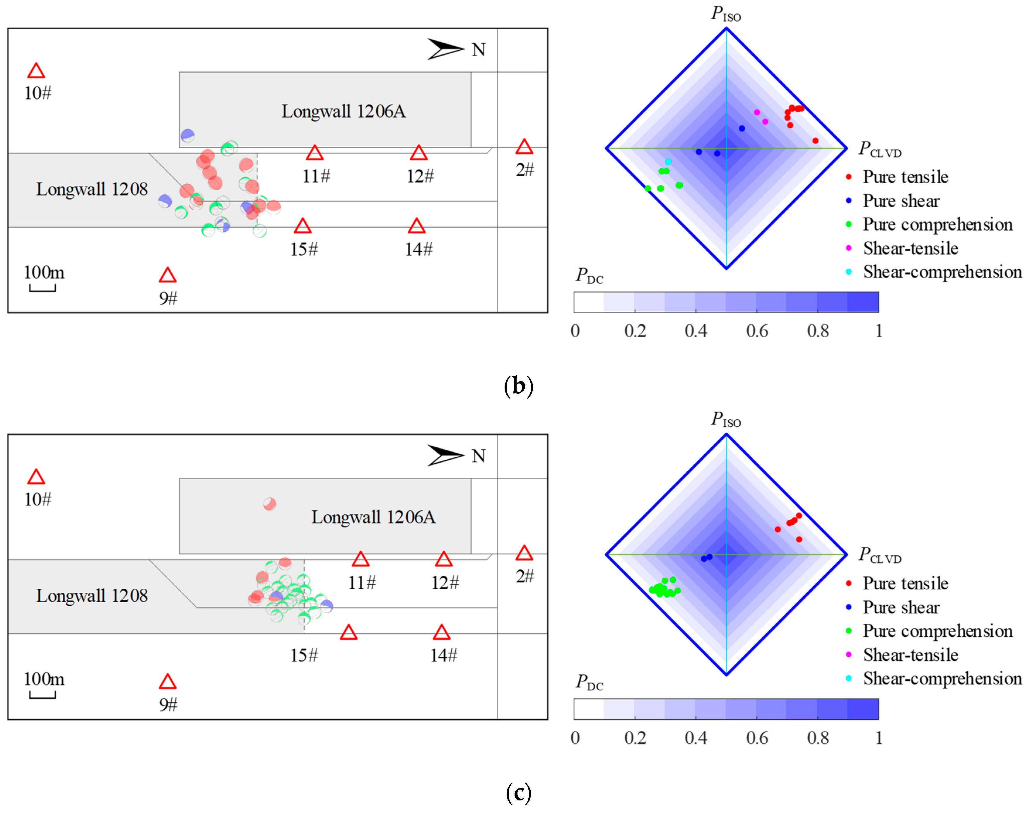
Before the SMT occurs, the layer underneath the super-thick layers breaks upwards step by step, resulting in a mining tremor. The focal mechanism of these mining tremors is solved one by one, and the evolution characteristics of the rupture mode of the source are analyzed to reveal the occurrence mechanism of the SMT. According to the different mining conditions, the mining process of LW 1208 is divided into three stages, corresponding to the solid coal mining stage and the goaf mining stage, respectively.
The focal mechanism of the SMT is directly represented by a diamond graph (as shown in Figure 14) [39]. At the mining stage of solid coal, the ratio of seismic numbers of different fracture types is: pure tension: pure shear: pure compression: shear-tension: shear-compression = 7:7:15:5:3 (seen in Figure 14a). Obviously, pure tension, pure shear, and pure compression are the main types of fracture mechanism source. The primary rupture of the roof is the main reason for the occurrence of tensile rupture mining tremors. Because of the small mined-out area and the limited roof fracture space, the roof compression failure constantly induces compressive fracture mining tremors. Under the influence of mining, the staggered instability of unstable roof blocks induces a series of shear fracture mining tremors.
Until the occurrence of the “8.20” and “8.29” SMTs, a total of 28 mining tremors were induced by the mining, which five and three of which occurred in June and July 2021, respectively. All of them were distributed in the peripheral area of LW 1208, indicating that the roof movement gradually relaxed while the internal elastic energy accumulated rapidly. In August 2021, there were a total of 20 mining tremors, including two SMTs. The source fracture types of mining tremors were mainly pure tensile and pure compression fractures. It was evident that the roof strata were gradually fracturing and the elasticity was rapidly released, eventually inducing the “8.20” SMT. Meanwhile, under the disturbance of the “8.20” SMT, the rock strata became unstable again, thus inducing the “8.29” SMT.
The distribution of the source rupture type of mining tremors occurring during the period from 29 August 2021 to 20 December 2021 was significantly different from those occurring from May to August; pure tension, pure compression, and pure shear fracture mining tremors occurred during this stage. Among them, there were 22 pure compression rupture mining tremors, accounting for 73% of total mining tremors. The number of mining tremors whose source rupture type is pure shear and tensile fracture type is 2 and 6, respectively. Similar to the occurrence mechanism of the “8.20” SMT, cracks first appeared and gradually expanded in the super-thick strata, and then devolved into tensile fractures with the continuous advance of LW 1208, which induced the “12.20” SMT.

5. Discussion

5.1. Comparison of SMTs with Mine Tremors and Earthquakes

The radiation energy of the SMTs was more than 105 J, The microseismic monitoring and surface separation detection results show that the source of the SMTs is located in the super-thick strata about 300 m above the coal seam, close to the surface. This is why the SMTs easily caused surface shaking. For example, before the occurrence of the “8.20” SMT, it increased from 0.24 m to 0.38 m (see Figure 7b), and before the “12.20” SMT, it increased from 0.76 m to 0.86 m (see Figure 7c). In addition, after the SMT occurred, the maximum surface settlement increased again. Different from the SMT, the radiation energy of mining tremors is about 104 J, which is triggered by the fracture of the rock layer under the super-thick strata. They do not cause ground shaking, and have little influence on the change of surface subsidence.
By comparing and analyzing the distribution characteristics of SMPs of SMTs and mining tremors in Table 4, it can be seen that: The seismic moment of the SMT is greater than 109 N·m, the apparent volume is greater than 107 m3, and the stress drop and apparent stress are greater than 104 Pa. The four SMPs of the SMT are one to three orders of magnitude higher than those of the mining tremors, indicating that the rock burst strength of the SMT is the highest, the disturbance scale is the largest, and the stress adjustment at the source is the most significant.
Relevant research shows that the seismic moment of SMTs is generally found in the range of 109–1012 N·m, and the stress drop and apparent stress are in the range of 104–106 Pa. The seismic moment, stress drop, and apparent stress of SMT calculated in this paper are generally located in the above ranges. The maximum seismic moment of the earthquake is more than 1015 N·m, and the stress drop and apparent stress are both greater than 106 Pa, which is significantly higher than that of the SMT.

5.2. Occurrence Mechanism of Strong Mining Tremors

Based on the above analysis, it can be further described that during the goaf mining of LW 1208, the roof strata above the coal seam breaks and collapses step by step. The whole process of SMTs induced by the fracture movement of the super-thick strata is shown in Figure 15.
As can be seen from the Figure:
(1)
The Jurassic Yan’an formation strata collapsed before the “8.20” SMT, the strata of Jurassic Anding and Zhiluo formation strata formed unstable rock blocks after fracturing, and the mutual movement and rotational extrusion of the blocks induced shear and compression fracture mining tremors, respectively. The super-thick strata did not break, but constantly deformed and accumulated elastic energy, resulting in an increase in surface settlement.
(2)
As LW 1208 continued to advance, cracks in the super-thick strata continued to expand and develop, and the initial tensile fracture of super-thick strata induced the “8.20” SMT.
(3)
After the occurrence of the “8.20” SMT, the super-thick strata was in a state of instability. Meanwhile, the disturbance of the SMT made the super-thick strata slip and mismove, which induced the “8.29” shear fracture SMT.
(4)
Mining continued at LW 1208, and cracks developed in the upper thick overburdened area within the mining area of LW 1206A. Further expansion of the cracks led to the tensile failure of the super-thick strata, and eventually induced the “12.20” SMT.
To summarize, the strata under the super-thick strata gradually break upward during goaf mining at LW 1208, and the super-thick strata deforms and constantly accumulates elastic energy. When the overlying load carried by the super-thick strata exceeds the bearing limit, the primary and periodic tensile fracture is the fundamental cause of inducing SMT. Meanwhile, the structural adjustment and staggered sliding of the super-thick strata after fracture also easily induces SMT.

6. Conclusions

The most common stratum of the roof in Ordos mining area is super-thick strata, and the fractures or slips of super-thick strata can easily trigger SMT. Field observations, numerical analysis, and theoretical calculations were used to study the mechanism of induced SMT caused by fractures in the super-thick strata in the Ordos mining area. The conclusions are as follows:
(1)
The SMTs induced by the fracture of super-thick strata are more likely to cause ground shaking. The SMTs are all located in the super-thick strata behind the goaf, which is relatively close to the ground. The apparent volume distribution is more than 107 m3, and the stress drop and apparent stress at the source are more than 104 Pa, which is one to three orders of magnitude higher than other mining tremors.
(2)
The SMTs were mainly caused by the movement of fractures in the super-thick strata. When solid coal mining was conducted, the surface subsidence was relatively small, and there were no fractures in the super-thick strata, thus SMTs did not occur. However, during goaf mining, there were two “stepped” increases in maximum surface subsidence, and fractures began to appear in the super-thick strata, leading to the occurrence of SMTs.
(3)
Theoretical calculations show that, during goaf mining, when LW 1208 advances by about 307 m, the super-thick strata will experience initial fracture. Then, when LW 1208 continues to advance approximately 118 m, there will be another fracture of the super-thick strata—a periodic fracture. This is the main reason for triggering the “8.20” and “12.20” SMT events. Moreover, after the super-thick strata are fractured, unstable structural adjustments can easily induce SMTs, such as the “8.29” SMT.
(4)
The strata below the super-thick strata gradually break upwards. Once the super-thick strata reach their fracture limit, it produces initial and periodic fractures in the form of tensional rupture, which can trigger SMT. Similarly, after tensional rupture occurs in the super-thick strata, the structural adjustment of the ruptured super-thick strata can produce shear failures that trigger SMTs.

Author Contributions

Conceptualization, Y.Y. and A.C.; methodology, Y.Y.; software, Y.L.; validation, Y.Y. and X.B.; formal analysis, Y.Y.; investigation, C.W. and A.C.; resources, S.W.; data curation, X.B. and Z.Y.; writing—original draft preparation, Y.Y.; writing—review and editing, A.C.; supervision, A.C.; project administration, A.C.; funding acquisition, A.C. All authors have read and agreed to the published version of the manuscript.

Funding

This research was funded by National key research and development program (2022YFC3004603) and National Natural Science Foundation of China (52274098, U21A20110).

Institutional Review Board Statement

Not applicable.

Informed Consent Statement

Not applicable.

Data Availability Statement

The data used to support the findings of this study are available from the corresponding author upon request.

Acknowledgments

The authors are grateful to Shilawusu Coal Mine for providing field testing. The authors would also like to thank the peer reviewers and Editors for their valuable comments and suggestions, which have greatly improved the manuscript presentation.

Conflicts of Interest

The authors declare no conflict of interest.

References

  1. Milczarek, W. Investigation of post inducted seismic deformation of the 2016 MW 4.2 Tarnovek Poland mining tremor based on DInSAR and SBAS method. Acta Geodyn. Geomater. 2019, 16, 183–193. [Google Scholar] [CrossRef]
  2. Bai, J.; Zhao, J.; Ren, Z.; Li, W.; Wang, K.; Li, X. Paleogeographic and sedimentary evolution of Meso–Neoproterozoic strata in the Ordos Basin, western North China Craton. J. Pet. Sci. Eng. 2022, 215, 110600. [Google Scholar] [CrossRef]
  3. Rudziński, Ł.; Mirek, K.; Mirek, J. Rapid ground deformation corresponding to a mining-induced seismic event followed by a massive collapse. Nat. Hazards 2019, 96, 461–471. [Google Scholar] [CrossRef]
  4. Wu, K.; Zou, J.; Jiao, Y.-Y.; Zhang, X.; Wang, C. Focal Mechanism of Strong Ground Seismicity Induced by Deep Coal Mining. Rock Mech. Rock Eng. 2022, 56, 779–795. [Google Scholar] [CrossRef]
  5. Lu, C.-P.; Liu, G.-J.; Liu, Y.; Zhang, N.; Xue, J.-H.; Zhang, L. Microseismic multi-parameter characteristics of rockburst hazard induced by hard roof fall and high stress concentration. Int. J. Rock Mech. Min. Sci. 2015, 76, 18–32. [Google Scholar] [CrossRef]
  6. Huang, B.; Liu, J.; Zhang, Q. The reasonable breaking location of overhanging hard roof for directional hydraulic fracturing to control strong strata behaviors of gob-side entry. Int. J. Rock Mech. Min. Sci. 2018, 103, 1–11. [Google Scholar] [CrossRef]
  7. Liu, J.; Liu, C.; Yao, Q.; Si, G. The position of hydraulic fracturing to initiate vertical fractures in hard hanging roof for stress relief. Int. J. Rock Mech. Min. Sci. 2020, 132, 104328. [Google Scholar] [CrossRef]
  8. Xu, C.; Fu, Q.; Cui, X.; Wang, K.; Zhao, Y.; Cai, Y. Apparent-Depth Effects of the Dynamic Failure of Thick Hard Rock Strata on the Underlying Coal Mass During Underground Mining. Rock Mech. Rock Eng. 2019, 52, 1565–1576. [Google Scholar] [CrossRef]
  9. Zhang, X.; Gong, P.; Wang, K.; Li, J.; Jiang, Y. Characteristic and Mechanism of Roof Fracture Ahead of the Face in an LTCC Panel When Passing an Abandoned Roadway: A Case Study from the Shenghua Coal Mine, China. Rock Mech. Rock Eng. 2019, 52, 2775–2788. [Google Scholar] [CrossRef]
  10. Xie, H.; Gao, M.; Zhang, R.; Peng, G.; Wang, W.; Li, A. Study on the Mechanical Properties and Mechanical Response of Coal Mining at 1000 m or Deeper. Rock Mech. Rock Eng. 2019, 52, 1475–1490. [Google Scholar] [CrossRef]
  11. Guo, P.; Yuan, Y.; Ye, K.; Sun, D. Fracturing mechanisms and deformation characteristics of rock surrounding the gate during gob-side entry retention through roof pre-fracturing. Int. J. Rock Mech. Min. Sci. 2021, 148, 104927. [Google Scholar] [CrossRef]
  12. Lu, C.-P.; Dou, L.-M.; Zhang, N.; Xue, J.-H.; Wang, X.-N.; Liu, H.; Zhang, J.-W. Microseismic frequency-spectrum evolutionary rule of rockburst triggered by roof fall. Int. J. Rock Mech. Min. Sci. 2013, 64, 6–16. [Google Scholar] [CrossRef]
  13. Konicek, P.; Waclawik, P. Stress changes and seismicity monitoring of hard coal longwall mining in high rockburst risk areas. Tunn. Undergr. Space Technol. 2018, 81, 237–251. [Google Scholar] [CrossRef]
  14. Zhang, C.; Jin, G.; Liu, C.; Li, S.; Xue, J.; Cheng, R.; Wang, X.; Zeng, X. Prediction of rockbursts in a typical island working face of a coal mine through microseismic monitoring technology. Tunn. Undergr. Space Technol. 2021, 113, 103972. [Google Scholar] [CrossRef]
  15. Sazid, M.; Ahmed, H.A. Stability Analysis of Shallow Depth Tunnel in Weak Rock Mass: 3D Numerical Modeling Approach. J. City Dev. 2019, 1, 18–22. [Google Scholar]
  16. Sazid, M. Effect of Underground Blasting on Surface Slope Stability: A Numerical Approach. Am. J. Min. Metall. 2023, 4, 32–36. [Google Scholar]
  17. Wang, F.; Kaunda, R. Assessment of rockburst hazard by quantifying the consequence with plastic strain work and released energy in numerical models. Int. J. Min. Sci. Technol. 2019, 29, 93–97. [Google Scholar] [CrossRef]
  18. Dou, L.; Sun, Z.; Li, X.; Liu, Q.; Gong, S.; Wang, C. Detection and targeted control of regional stress field for coal burst prevention. Geohazard Mech. 2023, 1, 69–76. [Google Scholar] [CrossRef]
  19. Yang, J.; Chen, W.; Tan, X.; Yang, D. Analytical estimation of stress distribution in interbedded layers and its implication to rockburst in strong layer. Tunn. Undergr. Space Technol. 2018, 81, 289–295. [Google Scholar] [CrossRef]
  20. He, J.; Dou, L.; Gong, S.; Li, J.; Ma, Z. Rock burst assessment and prediction by dynamic and static stress analysis based on micro-seismic monitoring. Int. J. Rock Mech. Min. Sci. 2017, 93, 46–53. [Google Scholar] [CrossRef]
  21. Laguillo, M.; Segarra, P.; Sanchidrián, J.A.; Beitia, F. A novel borehole surveying system for underground mining: Design and performance assessment. Measurement 2022, 194, 111021. [Google Scholar] [CrossRef]
  22. Chen, F.; Cao, A.Y.; Liang, Z.Z.; Liu, Y.Q. A Coal Burst Risk Assessment Model of Seismic Events Based on Multiple Seismic Source Parameters: A Case Study of the Huating Coal Mine, Gansu Province, China. Nat. Resour. Res. 2021, 30, 4515–4532. [Google Scholar] [CrossRef]
  23. Yang, S.; Song, G.; Kong, D. An evaluation of longwall face stability in thick coal seams through a basic understanding of shield–strata interaction. J. Geophys. Eng. 2019, 16, 125–135. [Google Scholar] [CrossRef]
  24. Yang, S.; Wang, J.; Li, L. Deformation and fracture characteristics of key strata based on the medium thick plate theory. J. China Coal Soc. 2020, 45, 2718–2727. [Google Scholar] [CrossRef]
  25. Reissner, E. Reflections on the Theory of Elastic Plates. Appl. Mech. Rev. 1985, 38, 1453–1464. [Google Scholar] [CrossRef]
  26. Wang, S.; Zhang, K.; Jiang, J.; Ji, S.; Pan, R. The fracture and rockburst laws of high-position hard and extremely thick red beds. J. Min. Saf. Eng. 2016, 33, 1116–1122. [Google Scholar] [CrossRef]
  27. Li, Z.-L.; Dou, L.-M.; Cai, W.; Wang, G.-F.; Ding, Y.-L.; Kong, Y. Mechanical Analysis of Static Stress within Fault-Pillars Based on a Voussoir Beam Structure. Rock Mech. Rock Eng. 2016, 49, 1097–1105. [Google Scholar] [CrossRef]
  28. Mendecki, M.J.; Wojtecki, Ł.; Zuberek, W.M. Case Studies of Seismic Energy Release Ahead of Underground Coal Mining before Strong Tremors. Pure Appl. Geophys. 2019, 176, 3487–3508. [Google Scholar] [CrossRef]
  29. Yamada, T.; Mori, J.J.; Ide, S.; Abercrombie, R.E.; Kawakata, H.; Nakatani, M.; Iio, Y.; Ogasawara, H. Stress drops and radiated seismic energies of microearthquakes in a South African gold mine. J. Geophys. Res. Solid Earth 2007, 112. [Google Scholar] [CrossRef]
  30. Song, C.-H.; Lu, C.-P.; Zhang, X.-F.; Wang, C.; Xie, H.-D.; Yan, X.-Y.; Yang, H.-W. Moment Tensor Inversion and Stress Evolution of Coal Pillar Failure Mechanism. Rock Mech. Rock Eng. 2022, 55, 2371–2383. [Google Scholar] [CrossRef]
  31. Dahm, T. Relative moment tensor inversion based on ray theory: Theory and synthetic tests. Geophys. J. Int. 1996, 124, 245–257. [Google Scholar] [CrossRef]
  32. Aki, K.; Richards, P.G. Quantitative seismology-theory and methods. Freeman 1980, 1, 116–119. [Google Scholar]
  33. Cao, A.; Chen, F.; Liu, Y.; Dou, L.; Wang, C.; Yang, X.; Bai, X.; Song, S. Response characteristics of rupture mechanism and source parameters of mining tremors in frequent coal burst area. J. China Coal Soc. 2022, 47, 722–733. [Google Scholar] [CrossRef]
  34. Ohtsu, M. Acoustic Emission Theory for Moment Tensor Analysis. Res. Nondestruct. Eval. 1995, 6, 169–184. [Google Scholar] [CrossRef]
  35. Yu, C.; Vavryčuk, V.; Adamová, P.; Bohnhoff, M. Moment Tensors of Induced Microearthquakes in The Geysers Geothermal Reservoir from Broadband Seismic Recordings: Implications for Faulting Regime, Stress Tensor, and Fluid Pressure. J. Geophys. Res. Solid Earth 2018, 123, 8748–8766. [Google Scholar] [CrossRef]
  36. Zhao, Y.; Yang, T.; Zhang, P.; Xu, H.; Wang, S. Inversion of seepage channels based on mining-induced microseismic data. Int. J. Rock Mech. Min. Sci. 2020, 126, 104180. [Google Scholar] [CrossRef]
  37. Ren, Y.; Vavryčuk, V.; Wu, S.; Gao, Y. Accurate moment tensor inversion of acoustic emissions and its application to Brazilian splitting test. Int. J. Rock Mech. Min. Sci. 2021, 141, 104707. [Google Scholar] [CrossRef]
  38. Gibowicz, S.; Harjes, H.; Schäfer, M. Source parameter of seismic events at Heinrich Robert Mine, Ruhr Basin, Federal Republic of Germany: Evidence for non double-couple events. Bull. Seismol. Soc. Am. 1990, 80, 88–109. [Google Scholar]
  39. Vavryčuk, V. Moment tensor decompositions revisited. J. Seismol. 2015, 19, 231–252. [Google Scholar] [CrossRef]
  40. Chen, D.; Martin Mai, P. Automatic identification model of micro-earthquakes and blasting events in Laohutai coal mine based on the measurement of source parameter difference. Measurement 2021, 184, 109883. [Google Scholar] [CrossRef]
  41. Calderoni, G.; Rovelli, A.; Di Giovambattista, R. Stress Drop, Apparent Stress, and Radiation Efficiency of Clustered Earthquakes in the Nucleation Volume of the 6 April 2009, Mw 6.1 L’Aquila Earthquake. J. Geophys. Res. Solid Earth 2019, 124, 10360–10375. [Google Scholar] [CrossRef]
  42. Ye, L.; Lay, T.; Kanamori, H.; Rivera, L. Rupture characteristics of major and great (Mw ≥ 7.0) megathrust earthquakes from 1990 to 2015: 1. Source parameter scaling relationships. J. Geophys. Res. Solid Earth 2016, 121, 826–844. [Google Scholar] [CrossRef]
  43. Kumar, A.; Kumar, A.; Gupta, S.C.; Mittal, H.; Kumar, R. Source parameters and fmax in Kameng region of Arunachal Lesser Himalaya. J. Asian Earth Sci. 2013, 70–71, 35–44. [Google Scholar] [CrossRef]
  44. Franceschina, G.; Gentili, S.; Bressan, G. Source parameters scaling of the 2004 Kobarid (Western Slovenia) seismic sequence. Phys. Earth Planet. Inter. 2013, 222, 58–75. [Google Scholar] [CrossRef]
  45. Bressan, G.; Kravanja, S.; Franceschina, G. Source parameters and stress release of seismic sequences occurred in the Friuli-Venezia Giulia region (Northeastern Italy) and in Western Slovenia. Phys. Earth Planet. Inter. 2007, 160, 192–214. [Google Scholar] [CrossRef]
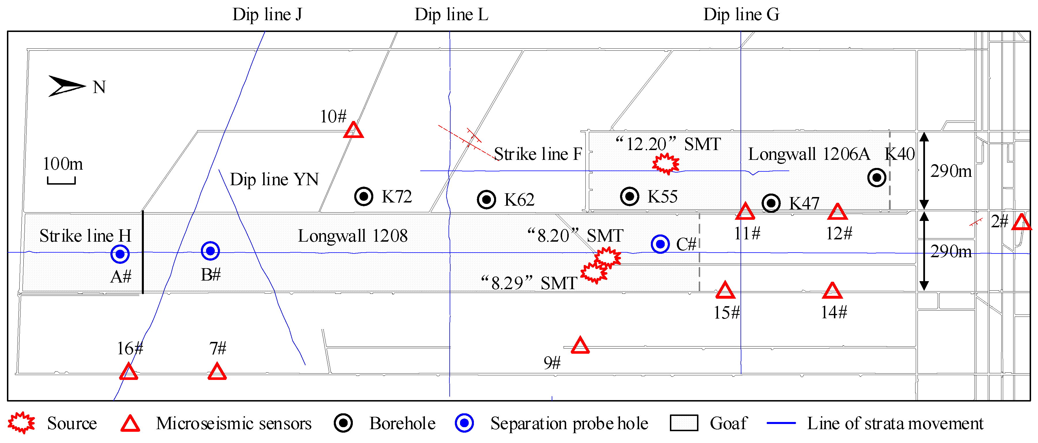
Figure 1. Layout of LW1208 and plane location of SMTs.
Applsci 13 05364 g001
Figure 2. Formation structure of LW 1208.
Applsci 13 05364 g002
Figure 3. (a) Plane distribution of mining tremors at different stopping stages in LW 1208; (b) Vertical upward distribution characteristics of mining tremors.
Applsci 13 05364 g003
Figure 4. The relationship between the SMPs f0, Es, rc, va, ∆σ and σapp with seismic moment M0 (a) f0M0; (b) M0Es; (c) rcM0; (d) vaM0; (e) ∆σM0; (f) σappM0.
Applsci 13 05364 g004
Figure 5. Characteristics of different strata separation detection in the mining process of LW 1208.
Applsci 13 05364 g005
Figure 6. Cloud map of surface subsidence evolution during mining of LW 1208. (a) 29 January 2021~26 April 2021; (b) 7 May 2021~8 September 2021; (c) 17 October 2021~30 December 2021.
Applsci 13 05364 g006
Figure 7. Surface subsidence of strike H line during mining of LW 1208. (a) 29 January 2021~26 April 2021; (b) 7 May 2021~8 September 2021; (c) 17 October 2021~30 December 2021.
Applsci 13 05364 g007
Figure 8. Mechanical model of the super-thick strata in the goaf mining stage of LW 1208. (a) Schematic diagram of mining stage of LW 1208; (b) Theoretical model of thick plate; (c) Boundary conditions of the super-thick strata.
Applsci 13 05364 g008
Figure 9. Force analysis of the cantilever in super-thick strata. A, B, and C are the number of the super-thick strata broken rock blocks; L is the periodicity fracture step of the super-thick strata; ∆ refers to the amount of rock rotation and subsidence; α is the rotation angle of block B; R is friction shear force; T is horizontal thrust between blocks; F is for support.
Applsci 13 05364 g009
Figure 10. “O-X” failure pattern in the super-thick strata and its relationship with the SMT.
Applsci 13 05364 g010
Figure 11. Principle of relative moment tensor inversion method.
Applsci 13 05364 g011
Figure 12. Criterion of focal mechanisms of mining tremor (normal vector n and slip vector v of focal plane).
Applsci 13 05364 g012
Figure 13. (a) Vibration waves of the “8.20” SMT; (b) Vibration waves of the “8.29” SMT; (c) Vibration waves of the “12.20” SMT.
Applsci 13 05364 g013
Figure 14. (a) Plane distribution of focal mechanism during solid coal mining (2 January 2021–28 April 2021); (b) Plane distribution of focal mechanism during goaf mining (29 April 2021–29 August 2021); (c) Plane Distribution of focal mechanism during goaf mining (30 August 2021–20 December 2021).
Applsci 13 05364 g014aApplsci 13 05364 g014b
Figure 15. Occurrence mechanism of SMT before and after goaf mining in LW 1208. (a) Cracks spread and subside rapidly; (b) Fracture and instability of super-thick strata; (c) Super-thick strata slip and stagger; (d) Super-thick strata tensile fracture.
Applsci 13 05364 g015
Table 1. Basic information of three SMTs in LW 1208.
Time of OccurrencePanel PositionSource LocationEnergy/JMagnitudeField Survey Condition
20 August 2021 17:41:51289.9 m in front of 06A open-off cut218 m behind the panel position of LW 1208 and 179.8 m behind the tail entry.5.56 × 1052.40(1) There was no obvious vibration in the underground and no deformation in the roadway;
(2) The ground shook slightly, and building facilities on the ground are normal;
(3) No loss of personnel or property.
29 August 2021 00:41:41Same as above (stoppage of LW 1208)264.6 m behind the panel position of LW 1208, and 57.2 m behind the head entry.1.69 × 1052.80
20 December 2021 17:03:15398.2 m in front of 06A open-off cut70.3 m behind the panel position of LW 1208, and 165.5 m to the west of the head entry.2.92 × 1052.60
Table 2. Detailed layout of detection positions of detection holes A, B, and C.
Detection Hole NameDetection Position NameDistance from 2-2 Coal Seam/mStratigraphic NameDetection DateSpatial Relationship with Mining Location
AA1345.9K1zh12 March 2020
15 May 2020
69.4 m behind detection hole A
297.7 m in front of detection hole A
A2320.5J2a
A3221.8J2z
BB1352.3K1zh15 May 2020
15 July 2020
147.3 m behind detection hole B
247.8 m in front of detection hole B
B2315.2J2a
B3219.5J2z
CC1447.6K1zh24 July 2021
23 August 2021
74.9 m behind detection hole C
29.9 m in front of detection hole C
C2444.8K1zh
C3310.2J2a
Table 4. Comparison of the size distribution of SMPs.
SMPsSeismic Moment/N·mStress Drop/PaApparent Stress/PaApparent Volume/m3
Chen et al. [40]109–1012104–106104–106/
Wu et al. [4]1010–1012104–105104–106/
Chen et al. [22]109–1012103–105104–106105–107
Calderoni et al. [41]1016–1018106–107106–107/
Ye et al. [42]1019–1023106–107106–107/
Kumar et al. [43]1017–1021106–108//
Franceschina et al. [44]1011–1016104–107104–107/
Bressan et al. [45]1012–1015104–107104–107/
Present research109–1010104–105104–105107–108
Disclaimer/Publisher’s Note: The statements, opinions and data contained in all publications are solely those of the individual author(s) and contributor(s) and not of MDPI and/or the editor(s). MDPI and/or the editor(s) disclaim responsibility for any injury to people or property resulting from any ideas, methods, instructions or products referred to in the content.