Article

Heat Transfer Optimization of an Electronic Control Unit Immersed in Forced Liquid Coolant

by
Cristina Georgiana Lates
1,*,
Catalin Gabriel Dumitras
1,
Petrica Vizureanu
2,3,* and
Andrei Victor Sandu
2,4,5
1
Faculty of Machine Manufacturing and Industrial Management, Gheorghe Asachi Technical University of Iasi, 39A D. Mangeron St., 700050 Iasi, Romania
2
Faculty of Material Science and Engineering, Gheorghe Asachi Technical University of Iasi, 41 D. Mangeron St., 700050 Iasi, Romania
3
Technical Sciences Academy of Romania, Dacia Blvd 26, 030167 Bucharest, Romania
4
Romanian Inventors Forum, Str. Sf. P. Movila 3, 700089 Iasi, Romania
5
National Institute for Research and Development in Environmental Protection (INCDPM), Splaiul Independentei 294, 060031 Bucharest, Romania
*
Authors to whom correspondence should be addressed.
Appl. Sci. 2023, 13(9), 5310; https://doi.org/10.3390/app13095310
Submission received: 18 January 2023 / Revised: 9 February 2023 / Accepted: 20 April 2023 / Published: 24 April 2023
(This article belongs to the Special Issue Fluid Flow and Heat Transfer: Latest Advances and Prospects)

Abstract

:
The current paper aims to present a cooling concept for future centralized platforms of ECUs (Electronic Control Units) from the automotive industry that involves grouping multiple electronic devices into a single system and cooling them with forced convection dielectric coolant. The enhancement consists of replacing the inside air of the module with a dielectric coolant that has a higher thermal conductivity than air and employing an additional prototype system that aids in forced liquid cooling. To meet automotive requirements, the experiments were exposed to an ambient temperature of 85 °C. Temperature measurements on these solutions’ hot spots were compared to those on a thermal paste-only reference electronic module. This study used DFSS (Design for Six Sigma) techniques to determine the ideal pump flow rate, fan air flow rate, and liquid volume in the housing, leading to an optimization in heat dissipation. Finding a trustworthy transfer function that could forecast the impact of the crucial design parameters that had been found was the main goal. The electronics cooled by forced convection coolant improved heat dissipation by up to 60% when compared to the reference module. This demonstrates that the DoE (Design of Experiments) method, which is based on a limited number of measurements, can estimate the behavior of the ECU without the need for a more involved theoretical framework.

1. Introduction

ECUs are widely used in the automotive industry. The number of functions that these ECUs must complete has steadily increased in recent years. New requirements and the latest technologies have created numerous opportunities and possibilities for the development of new applications and functions for automobiles that users can connect with. As part of the IoT (Internet of Things), vehicle modernization will result in the integration of ECUs into standardized High-Performance Computers (HPC). Because of the trend toward centralized computation with dynamic resource allocation, the focus markets of this cluster may overlap with other automotive controller and infotainment applications.
Autonomous car applications will dominate the automotive AI (artificial intelligence) market, and computing will dominate the HW costs. By 2028, the computing HW market will be worth $13 billion, accounting for roughly 10% of total electronic control unit markets. The second-most common HPC-HW application in automotive is infotainment. By 2028, AI computing for infotainment will be worth $0.8 billion [1,2]. Memory is another important IC (integrated circuit) market in the automotive sector, with $2.5 billion in 2017 and average growth of 20% expected in the near future [3]. The exponentially increasing data volumes and rates, both in the wired and wireless domains, are a major industry trend.
End-users in automotive interior electronics are increasingly expecting the same innovative features found in consumer electronics, such as curved and flat displays, haptic feedback, and so on. Introducing these technologies into automotive markets while maintaining long-term reliability is a difficult task, where materials and methods for PCB (Printed Circuit Board) assembly play a critical role. These are the factors that increase the power of the vehicle’s ECUs. To compete in the market and meet customer demands, machine manufacturers must provide these features and services. Because of the large amount of power required to perform functions, the cooling of electronic components in the automotive industry has begun to be limited. A scalable “add-on” cooling solution for electronics is an interesting and appealing addition to the product/solution, appealing not only for HPC but also for growing markets of battery/hybrid vehicles [4,5] and TCUs (Telematic Controls Units) or lidar and radar products, where the trend is to pack more powerful chips into a more compact space, passive cooling is reaching its limits, and new solutions are sought.
Currently, heat transfer systems for ECUs in conventional cars are overly conservative, with thermal paste, metal housings, or fan cooling solutions being the most common [6]. The benefits of these technologies are that they are inexpensive, but numerous air-filled spaces can be found inside the module due to design restrictions on housing production. Air has no effect on the heat transmission of electrical components because it is an insulating medium. Indirect contact cold plate cooling using an ethylene glycol/water mixture or R134a as working fluids has been used in recent years [7], but it has drawbacks such as being influenced by the thermal resistances of the materials used in between, having poor temperature uniformity, low stability for temperature control, and the heat dissipation capacity being highly dependent on the flow rate.
Air cooling has the advantages of simplicity and low cost. It does away with the need for cooling loops and any worries about liquid leaking into the electronics. The most significant disadvantage of air cooling is its inefficiency. Even with high-powered blowers, air cooling cannot transport as much heat as a liquid system [8]. This has caused issues for EVs (electric vehicles) in hot climates, and blower noise can also be a problem. The acoustic behavior, however, depends strongly on the size of the fan used at a particular airflow [9]. Nonetheless, air cooling solutions serve a purpose and provide value.
While most major OEMs in the passenger car market use air or indirect liquid cooling methods, new methods to meet the increasing thermal demand on high-performance computers are required. This is especially true when it comes to more specialized markets like electric construction vehicles. In this scenario, a large amount of power is required, which generates a significant amount of heat. Liquid cooling could be one of these emerging technologies for automotive electronics thermal management. It could be direct or indirect liquid cooling.
Currently, liquid cooling solutions are used in automotive for the cooling of battery systems. The market for novel energy vehicles has grown rapidly in recent years. Power batteries are one of the most important components in electric vehicles (EVs) and hybrid electric vehicles (HEVs). Thermal Management systems are equally important as battery cell chemistry because the battery cell’s life depends on them. During the charge and discharge process, a large number of battery cells generate a lot of heat and cause temperatures to rise [10,11]. The operating temperature of a cell has a significant impact on its voltage, energy, efficiency, and life cycle [12]. Further thermal runaway and safety issues can occur if heat is not effectively dissipated [13,14]. Because liquid has a higher specific heat and thermal conductivity than air, it can effectively mitigate battery temperature rise and prevent battery overheating at the expense of a more complex system.
Currently, there are vehicles in production that use mainly indirect liquid cooling. Tesla has developed a novel method for cooling the thousands of cylindrical cells housed in the chassis. Tesla uses a metallic cooling tube that snakes through the EV battery pack, according to the patent [15]. By maintaining contact with the surface of each cell, this flexible tube provides direct cooling. To manage battery heat, GM’s Chevy Volt [16] has a liquid cooling system with glycol. A plastic frame surrounds each battery cell. The coolant plate frames are then stacked longitudinally to form the entire pack. Both Tesla’s and GM’s systems have one big drawback, and the heat transfer coefficient of glycol could be improved. Additional research showed the advantages of indirect coolant performance, such as new liquid cold plate concepts that are well suited for single-sided cooled packages as well as double sided cooling of stacked press-pack-type modules [17].
Direct immersion cooling is classified into two types: single-phase immersion cooling (SLIC) and two-phase liquid immersion cooling (TLIC) (2PIC). This method takes advantage of dielectric fluids, which, because of their high dielectric strength, have very little electrical conductivity. This makes it possible for the cooling liquid to come into direct contact with the electronic components, increasing the cooling capacity of the method and addressing the drawbacks of indirect liquid cooling. Immersion cooling, which is based on immersing the electronic components with dielectric fluid to increase cooling efficiency, is the most popular cooling approach for this method. Immersion cooling has previously been demonstrated mainly in electronics for data centers [18,19], high-power electronic device systems [20,21], and grid power systems but is now seeing interest in the electric and conventional vehicle markets. The operational complexity, the problem of hysteresis of the boiling curve and evaporation, and the high cost of 2PIC [22] make this option less feasible to implement on the electronic modules on the vehicle, and for this reason they are not the purpose of this experiment. However, the SLIC solution appears to be more promising.
Several studies have demonstrated the advantages of using single-phase fluids. It demonstrated that the given technology reduces heat flow barriers while maintaining the mechanical properties of the package. Schulz-Harder et al. [23] concluded that direct liquid cooling of base plates produced the best results, and stacked liquid-cooled modules enabled switching high power in a small volume. GRC Electrosafe [24], a hydrocarbon-based fluid, was shown to have significantly better heat transfer than an air-cooled solution. Wang et al. [25] discovered that direct liquid cooling could reduce the thermal resistance of a junction to a heat sink by more than 50% due to the elimination of the thermal grease layer. As a result, active and passive temperature fluctuations are significantly reduced, which can improve module reliability and life.
Spray cooling, a promising cooling solution that uses a direct coolant and has applications on high-performance computers and data centers, aerospace and spacecraft, or hybrid electrical vehicles [26,27], has a 409.3% better heat transfer coefficient than forced air, according to an investigation on battery thermal management by Wu et al. [28]. The disadvantages identified by Yin et al. [26], which include the complexity of the nozzles structural design, long-term corrosion and blockage of the nozzles, and the complicated interrelationship between all parameters considered for the system, including spray parameters, working fluid type, surface modification, and environmental parameters to obtain a good system performance, all lead to the conclusion that the use of spray cooling in a vehicle ECU appears to be challenging. Immersion cooling, which employs dielectric fluids, has emerged as one of the most promising methods of removing heat from high power densities compared to indirect cooling, according to Scott’s classification [29].
SLIC technology is widely used in data centers, and liquids are recirculated to improve thermal management. Mineral oil outperformed silicone oil, synthetic esters, and natural esters in terms of thermal performance. Because of its low cost, toxicity, and wide operating temperature range, mineral oil is an excellent choice for battery immersion cooling systems and data centers [30,31,32,33,34]. It also has no impact on the reliability of electronic devices or the increasing corrosion rates [35]. A study with perfluorocarbon-structured refrigerant (Fluorinert) demonstrated that it can be used as an immersion coolant with natural convection in a data center [36]. Immersion cooling, which immerses the battery in a dielectric fluid, has the potential to increase heat transfer rate by 10,000 times over passive air cooling, as recently reported by Roe et al. [37].
To investigate additional thermal solutions for electric vehicle batteries, many studies use hydrofluoroether [38,39] or natural and synthetic esters [31,40,41]. There is an effort to demonstrate that by enhancing their properties with nanoparticles, biodegradable materials can match the properties of mineral oil [42,43]. In comparison to their basic conventional fluids, nanofluids were shown to have much enhanced thermal properties, particularly thermal conductivity and convective as well as boiling heat transfer features. These novel fluids not only possess desirable high thermal properties but also have several advantages and applications in other fields, including electronics [44,45]. Novec 3283, Novec 43, 50 cSt silicone oil, 20 cSt silicone oil, and soybean oil were tested as single-phase immersion coolants [46]. Because of its lower viscosity, the 20 cSt silicone oil performs better in natural convection than the 50 cSt silicone oil. The viscosity of the fluid is critical to pumping efficiency. When compared to existing mineral base oils used in driveline formulations, synthetic fluids such as PAO have a wider range of viscosities and can go to much lower viscosities (2 cSt, KV 100 °C). This implies that synthetic fluids with lower viscosity can provide better pumping efficiency and possibly better heat transfer efficiency in the system. On the other hand, immersing electronic components in viscous coolants provides a slight mechanical advantage. Depending on the fluid’s viscosity, it may also act as a damper to help stop vibrations and shocks [47,48]. The characteristics of typical dielectric liquids are low density, low boiling point, non-reactivity, non-corrosivity, and strong chemical and thermal stability.
Although there is a large amount of literature on thermal immersion cooling and cost savings, there is little literature on the impact of immersion cooling on the reliability of information technology (IT) equipment such as PCBs and electronic packages. Ramdas et al. [49], focusing on the change of thermo-mechanical properties of PCBs when immersed in dielectric fluid and the effect of the change on the reliability of electronic packages, showed that Young’s modulus is decreasing for PCBs after immersion in dielectric coolant, which is likely to increase the reliability of electronics packages. Moreover, research by Muslim [50] using a variety of dielectric liquids has demonstrated that the dielectric properties are satisfactorily stable and undergo minimal change over time, even when exposed to high temperatures. Additionally, electrical component oxidation and corrosion will be prevented, contamination from dust, debris, and particles will be decreased [34], and the performance of electronic components will increase [34,51,52].
Immersion cooling has not yet been used in the automotive industry to cool an ECU; instead, it is primarily used to cool data centers and occasionally to cool the batteries in electrical vehicles. The current paper proposes a cooling concept for future centralized platforms of ECUs in conventional vehicles and EVs that involves grouping multiple electronic devices into a single system and cooling them with recirculated dielectric coolant. According to this active cooling solution implemented to increase the heat transfer of the entire system, the current paper attempts to establish an optimal configuration between fan airspeed, pump airflow rate, and housing coolant volume. The system will be exposed to an ambient temperature of 85 °C. From international standards used in automotive ISO 16750-1 and ISO 16750-4 for environmental conditions and testing for electrical and electronic equipment of road vehicles, this temperature was selected to cover the thermal requirements for ECUs mounted on passenger, luggage, and load compartments or ECUs mounted on the exterior or in cavities. The choice of coolant fluid is obviously critical in this case. As a new cooling technology proposed for automotive, there is still a lack of research addressing the lifetime, fluid stability, material compatibility, and understanding of sustainability. To evaluate the cooling benefits, temperature measurements on the hot spots of these solutions were compared to a reference electronic module cooled only by thermal paste.

2. Experimental Validation

2.1. Electronic Module Description

The reference electronic module used in the experiments, as shown in Figure 1a, consists of a PCB placed in aluminum housing and covered by steel upper housing. For monitoring junction temperatures, there are five temperature-measuring points: a PCB, a microcontroller (μC), two buck converter integrated circuits (ICs), and a two-phase DC-to-DC boost converter IC with serial peripheral interface (SPI), all of which have embedded thermal sensors. The microcontroller’s roles include managing all LED functionalities, reading the temperature sensor on the PCB, detecting under- and overvoltage supply conditions, and managing LED drivers over the SPI bus. While the boost converter maintains a steady power supply for the LED drivers using the vehicle’s battery supply voltage, the buck converter controls the LED current. Thermal Interface Material (TIM) is used under the PCB in the reference module, where components Boost, Buck1, and Buck2 are located. The compound between the PCB and the heatsink bridges the air gap, which otherwise prevents heat from moving efficiently.
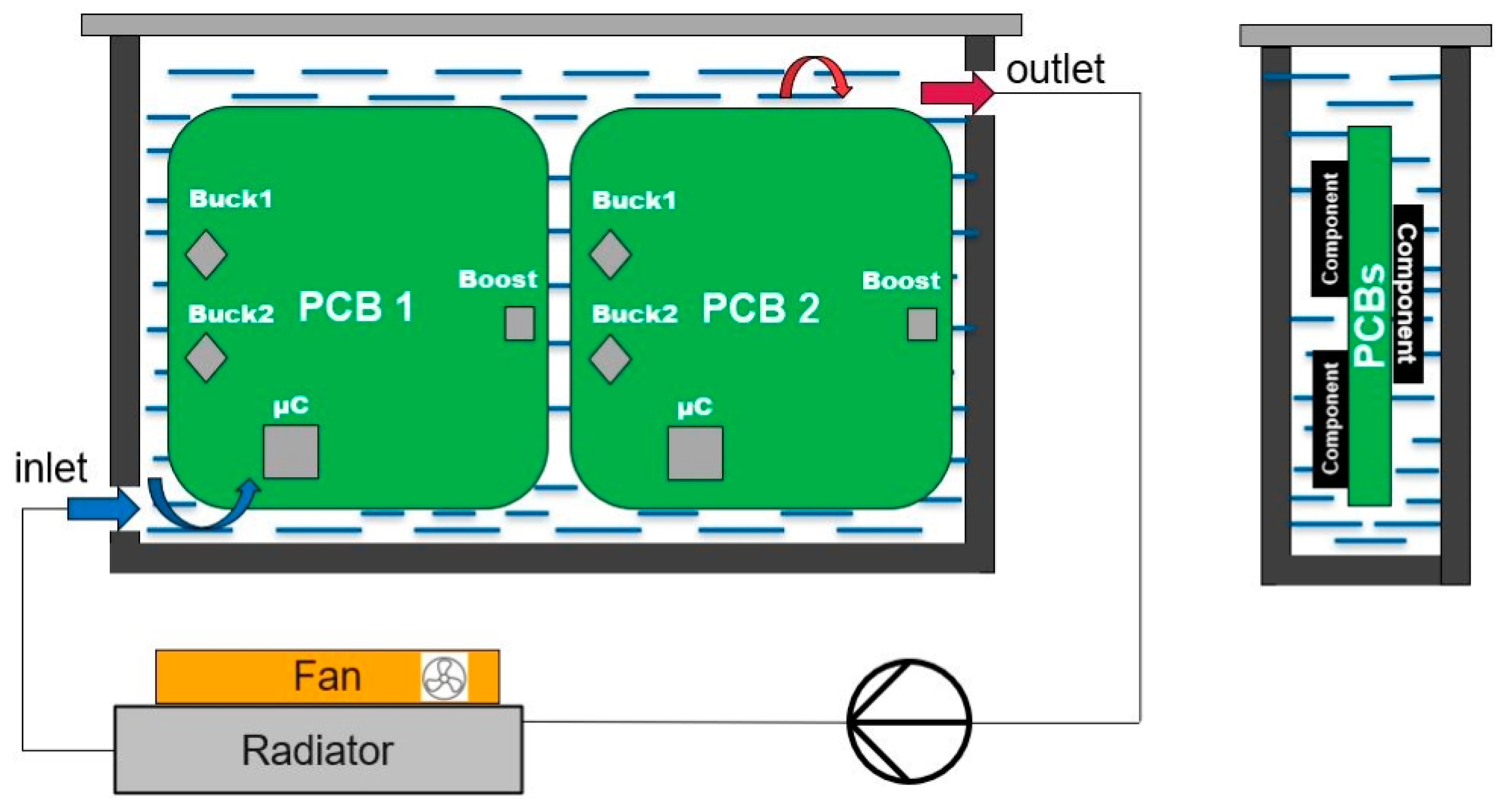
The reference module is cooled only by thermal paste, which is the most used cooling solution in automotive electronic modules. In this reference measurement, the main heat transfer path from the hot spot to the housing is via thermal paste only, as illustrated in Figure 1b. In the proposed experiment for this study presented in Figure 2, the main heat transfer path is via forced convection and molecular conduction of the fluid. When the surrounding fluid is a liquid, radiation from the heat-producing components is nonexistent.
In this experiment, two PCBs were used for this system, as shown in Figure 2, which were immersed in a plastic housing. The electronic components are fully submerged in the dielectric fluid, which will act as a heat transfer medium between the electronic components and the surrounding air. The coolant liquid is circulated throughout the system by a low-pressure pump. The liquid is then cooled by passing it through a copper heat sink, over which a fan is mounted.
The Design for Six Sigma (DFSS) methods were used to identify the most critical design parameters for the heat dissipation of the system. Requirements were identified, and QFD (Quality Function Development) assisted in translating them into product specifications. Thermal resistance from component to ambient (total thermal resistances), hot spot temperature, and pump flow rate are critical engineering parameters to meet the product criteria, according to House of Quality 1 (HoQ1). These three CtQs were carried over into House of Quality 2 (HoQ2) in order to determine critical design characteristics. Moreover, the development of hierarchical decomposition revealed that the system’s principal purpose is to regulate inside-to-outside heat transfer, with a focus on forced convection and system optimization between conduction and convection. Additionally, the functional decomposition method was utilized to pinpoint how important design parameters affect fundamental function in the area of study. The design parameters identified with these methods are pump flow rate, fan airflow, and fluid volume from the housing, which are controllable in the investigation to analyze their influence on the hotspots. The values of the design parameters were fixed based on the equipment capabilities of these solutions (pump, heatsink, and fan) to resist a high ambient temperature. But the main goal of this study is to examine how these three design parameters interact with one another and to utilize the transfer function obtained from DoE to predict the hotspot temperatures using alternative design parameter values based on statistics.
The fan has variable speed. For speed control, the fan was connected to a source, and the supply current was varied to obtain the desired test flow rates of 3.2 m/s and 1.75 m/s, respectively. In order to make sure that the air flow of the fan has the desired value at the current and voltage values chosen from the source, measurements were made with the PEAKMETER PM6252B anemometer, manufacturer Peakmeter, country of origin China This anemometer is used to measure the average speed of the fan. To determine the exact air flow, a tunnel with fan dimensions of 120 mm × 120 mm was used.
In order to monitor the temperature of the liquid, type K thermocouples were used, positioned both at the entrance of the liquid into the casing and at the exit. A PicoLog TC-80 data acquisition system was used to record temperatures. An interface allows the measurement device to communicate with the computer, and the measurement data are displayed in numerical and graphical form.
The pump used is powered by a 120 VAC power cable and has three power steps: 38 W at 3 m of pressure, 52 W at 4.5 m of pressure, and 72 W at 4.5 m of pressure. The centrifugal pump has an advantage in this application because it features a changeable valve or aperture in the delivery pipe that allows the flow volume to be regulated without overtaxing the motor. To achieve the calculated flow rates of around 0.63 L/min for stage 1 and 1.54 L/min for stage 3, we had to limit the flow rate using an 8 mm reduction per circuit.
The thermophysical properties of the coolant chosen are listed in Table 1. Due to its low kinematic viscosity, sufficient flash point, material compatibility, and low cost, a synthetic hydrocarbon (SHC) was used to cool electronic components via heat transfer. The coolant is both electrically insulating and a good thermal conductor. At 50 °C, this fluid has a specific heat capacity of 2.2468 KJ/kg/K. The fluid also has a flash point of 228 °C, which is higher than the minimum required flash point of 150 °C and the commonly required flash point of 200 °C.

2.2. Test Setup

The modules were tested in the climatic chamber at an ambient temperature of +85 °C. This selected ambient temperature covers testing at high temperatures used frequently in the automotive industry. The module operated in full power mode, which means around 50 W of power per PCB at the ambient temperature values described above. The dielectric liquid system was placed in the thermal chamber together with the reference electronic module cooled by thermal paste only, as shown in Figure 3, to correlate the measurements in the same environmental conditions at the same time and compare the heat dissipation performance.
The effect of different experimental variables on heat transfer was investigated using a two-level full factorial design. Two variables were used to identify significant effects and interactions between them: pump flow rate (0.63 L/min and 1.54 L/min), fan air flow rate (1.75 L/s and 3.2 L/s), and liquid volume in the housing (0.3 and 0.4 L) at an ambient temperature of 85 °C. Using the experimental data, a polynomial regression model was created. Minitab (version 20.1.3.0), a statistical software tool, was used to run the DoE with a 2k full factorial approach to obtain a prediction of the critical design parameters. After any change in a variable, the cooling system was held for 35 min so that the internal temperature of the components and the whole system could be stabilized. The temperature measurements for this analysis were evaluated after this time interval, before changing the next variable and considering five different measurements. However, to simplify this evaluation, a median of those five temperatures after time tst (stabilization temperature time) was considered.

3. Experimental Results and Discussion

The response values T_PCB, T_Boost, T_Buck1, T_Buck2, and și T_ μC are the results of the values measured during the experimental tests. To determine the effects of the set parameters, they were simulated in 16 trials, as presented in Table 2. To simplify this analysis, the statistical analysis only on the Buck1 component will be presented in the following paragraphs.
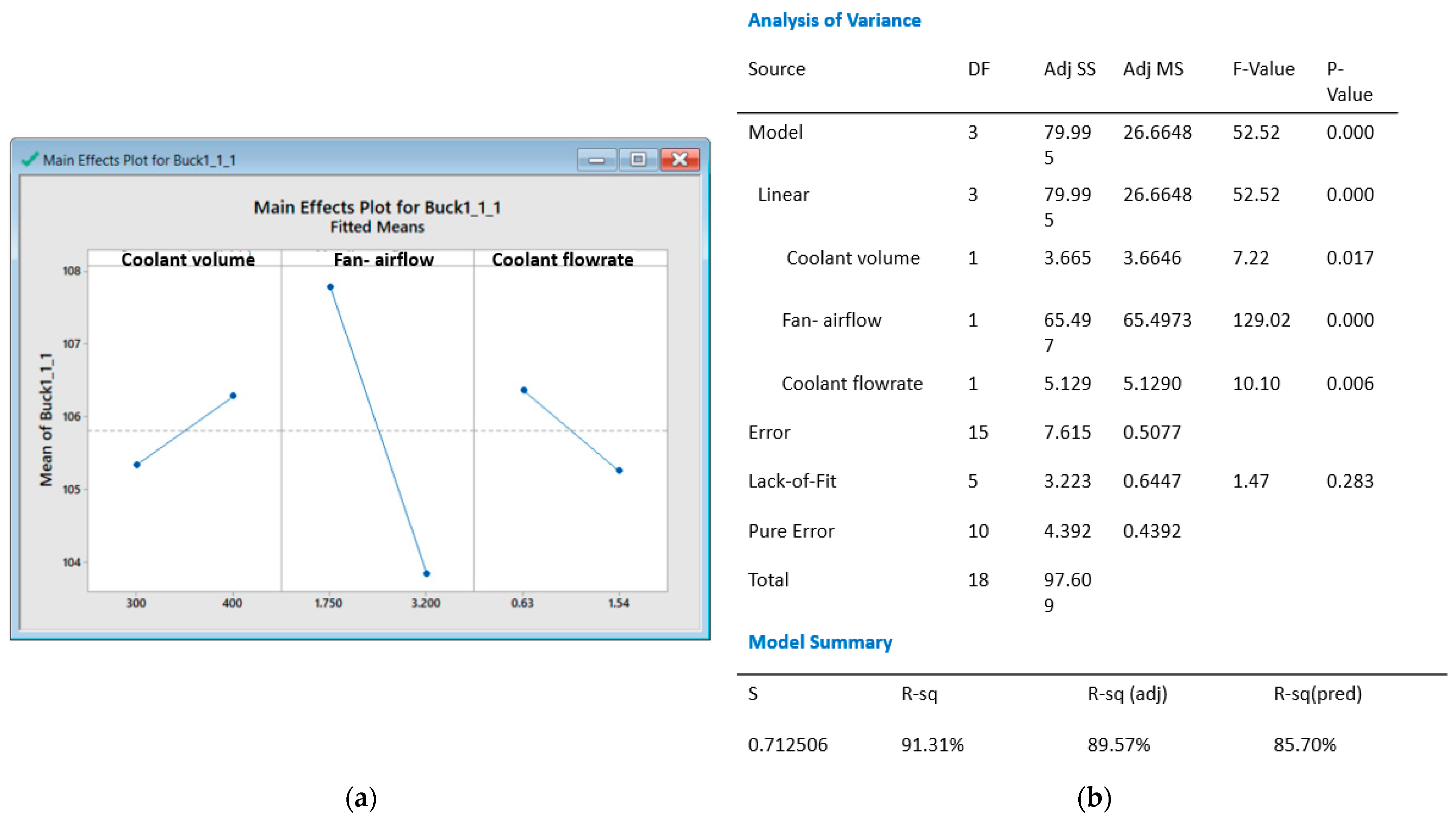
First, the main effects of this experiment were calculated. That means determining the main effects of pump flow rate, fan air flow rate, and liquid volume in the housing. During the evaluation in Minitab, it was interesting to evaluate the interactions of these three factors to analyze if there is a meaningful combination of input settings that impact the lowest temperature on the Buck1 component. For the statistical analysis performed on the Buck1 component, insignificant interactions ((3-way interactions of all 3 variables) (volume of fluid in the housing × fan airflow × pump flow rate)) were reduced from the analyze factorial design to simplify the model and to obtain a hierarchical model. Only significant effects were retained. The significant interactions are highlighted in normal distribution plot, illustrated in Figure 4a and also in Figure 4b where Pareto chart is depicted, the effects declined in accordance with their importance. The red vertical dashed line is our significance limit. The component temperature is dependent on all three effects, as illustrated in Figure 4: the volume of fluid in the housing, the fan airflow, and the pump flow rate. The amount of liquid in the casing had the least impact on temperatures, while the fan’s airflow had the most impact.
The P and the R-sq values, visible in Figure 5, are two values that indicate that we have obtained a reliable model and that the three main factors are significant based on the measurements and the statistical model used. The observed probability, the P-value, is less than 0.05, and the R-sq value indicates that we have a reliable model. The values of these two parameters indicate that we have obtained a transfer function. The transfer function is a mathematical function that theoretically identifies the variables that have a significant impact on the hotspot temperatures, and if the function is not known, statistics can be used to determine it. The measurement data of the hotspot presented in Table 2 for each of the 16 trials gathered during tests and imported into the Minitab statistical program led to the derivation of the transfer function. Therefore, using Minitab, the following is the final transfer function:
T_Buck1_85C = 110.58 + 0.00944 × Coolant volume − 2.725 × Air_flow rate (fan) − 1.227 × Coolant flow rate (pump)
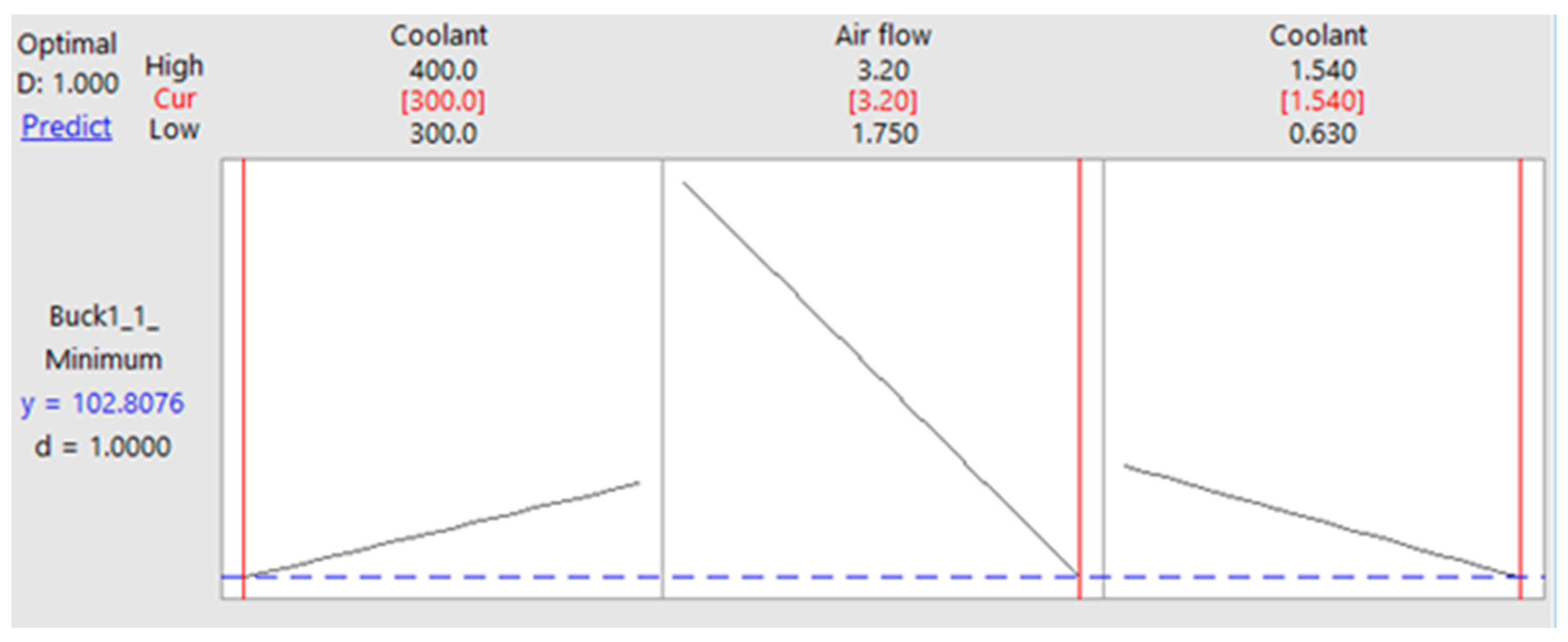
A response optimizer was performed with Equation (1), and Figure 6 shows that to achieve a target value for the hotspot temperature, the maximum performance curve of the fan, the minimum amount of liquid, and the maximum flow rate of the pump must be used from the analyzed range. However, the results showed that the lowest temperatures were recorded when the case contained the least amount of liquid because it would be advantageous to recirculate the liquid, cooled by the radiator and fan, more easily and faster.
The following parameter values will result in the lowest Buck component temperature (~103 °C), as shown in Figure 7, where a cube plot was performed: The pump flow rate is 1.54 L per minute, the fan air flow rate is 3.2 L per second, and the coolant volume in the housing is 300 mL.
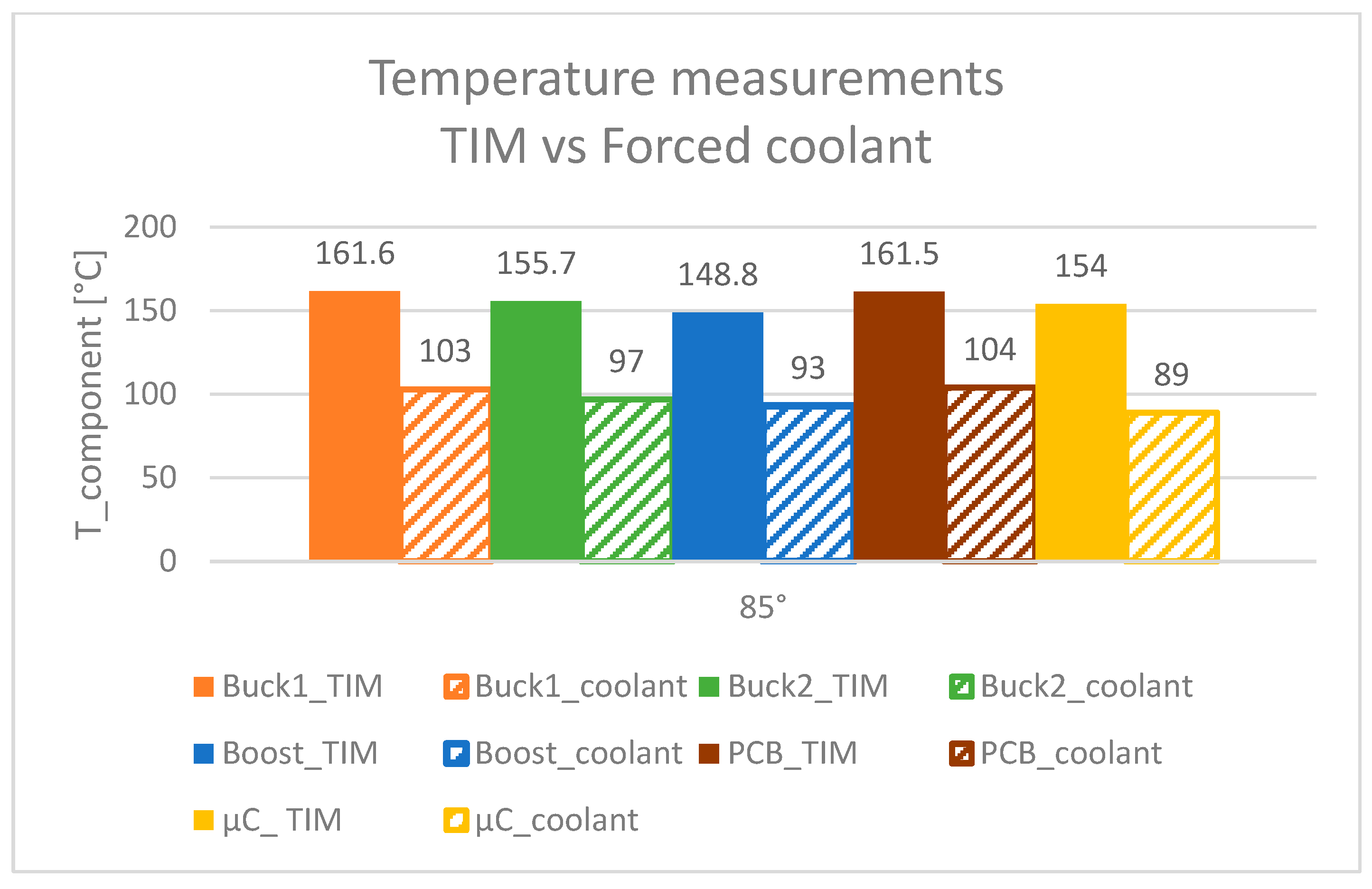
To evaluate the cooling benefits, temperature measurements on the component hotspots of this optimized solution were compared to the temperature measurements of a reference electronic module cooled only by thermal paste. The measurements, visible in Figure 8, were achieved in the same conditions in the thermal chamber in order to have a more accurate comparison.

4. Conclusions

In this study, a cooling concept for future centralized platforms of automotive electronic modules, which involves grouping multiple electronic devices into a single system and cooling them with recirculated dielectric coolant, is investigated. Measurements and explicit model predictive control based on the statistics method for the proposed immersion liquid cooling system have made some significant achievements, as listed below:
  • The smallest temperatures on the hotspots were achieved with the highest coolant flow (1.54 L/min), the highest airflow (3.2 L/s), and the smallest quantity of liquid in the housing (300 mL);
  • According to this statistical method, the fan airflow value has the greatest influence on the temperatures of electronic components. It also has the greatest influence on the slope from the lowest to the highest flow rate;
  • Cooling is also affected by pump flow. The best results were obtained when the flow rate was increased to 1.54 L/min. The pump, of course, requires power to operate, and unfortunately, most of this energy is expanded in the coolant as heat. As a result, the power consumed by the pump raises the total heat rejected. However, the benefits of forced liquid cooling’s small temperature gradients and increased cooling rates easily outweigh the disadvantages of increased system complexity;
  • Temperatures were least affected by the volume of liquid in the casing. The results, however, revealed that the lowest temperatures were recorded with the least amount of liquid in the casing because of the advantage of faster recirculation of the liquid, cooled by the radiator and fan. Due to design constraints, a smaller amount of liquid could not be tested in these experiments;
  • These measurements show that the single-phase liquid cooling system with forced convection achieved up to 57% lower temperatures on Buck1, 73% lower temperatures on μC, 60% lower temperatures on Boost, and 55% lower temperatures on the PCB overall temperature when compared to thermal paste cooling solutions for the used boundary conditions.
OEMs typically request automotive-grade components to ensure dependable and safe operation over the vehicle’s long lifespan in harsh environmental conditions. While the technology shows promise with technically excellent performance, the increased weight and cost compared to currently used methods will make immersion cooling difficult to enter the mass-production automotive market. However, regulations concerning the thermal safety of electric vehicles are changing, and this emerging technology may begin to take a larger market share. Furthermore, the flame-retardant properties of the fluids serve as a safety feature, preventing thermal runaway events from spreading between electronics or battery cells. The choice of coolant fluid is obviously critical in this case. As a new cooling technology proposed for automotive, there is still a lack of research addressing the lifetime, fluid stability, material compatibility, and understanding of sustainability. Hermetical sealing of the ECU and expansion of the coolant should also be considered. This conclusion is encouraging for discussions about module weight, a critical topic in the automotive industry.

Author Contributions

Conceptualization, C.G.L. and C.G.D.; methodology, C.G.D.; software, C.G.L.; validation, C.G.L., C.G.D. and P.V.; formal analysis, C.G.L.; investigation, C.G.L.; resources, C.G.L.; data curation, C.G.D.; writing—original draft preparation, C.G.L.; writing—review and editing, P.V.; visualization, A.V.S.; supervision, P.V.; project administration, A.V.S.; funding acquisition, P.V. All authors have read and agreed to the published version of the manuscript.

Funding

This research was also supported by TUIASI from the University Scientific Research Fund (FCSU).

Institutional Review Board Statement

Not applicable.

Informed Consent Statement

Not applicable.

Data Availability Statement

Not applicable.

Conflicts of Interest

The authors declare no conflict of interest.

References

  1. Yole Development. Computing and AI for Automotive. 2022. Available online: https://www.yolegroup.com/product/report/computing-and-ai-for-automotive-2022/ (accessed on 24 November 2022).
  2. McKinsey & Company. Automotive Software and Electrical/Electronic Architecture: Implications for OEMs. 2019. Available online: https://www.mckinsey.de/industries/automotive-and-assembly/our-insights/automotive-software-and-electrical-electronic-architecture-implications-for-oems (accessed on 21 November 2022).
  3. Research and Markets. Automotive Memory Market–Global Outlook and Forecast 2019–2024. Available online: https://www.researchandmarkets.com/reports/4749337/automotive-memory-market-global-outlook-and (accessed on 18 November 2022).
  4. Capata, R. Urban and Extra-Urban Hybrid Vehicles: A Technological Review. Energies 2018, 11, 2924. [Google Scholar] [CrossRef]
  5. Mahesh, S.P.; Bang, Y.-M.; Seo, J.-H.; Kim, D.-W.; Lee, M.-Y. Heat transfer characteristics of electronic control unit heatsink for 72v neighborhood electric vehicle. In Proceedings of the Asian Conference on Thermal Sciences 2017, 1st ACTS, Jeju, Republic of Korea, 26–30 March 2017. [Google Scholar]
  6. Mallik, S.; Ekere, N.; Best, C.; Bhatti, R. Investigation of thermal management materials for automotive electronic control units. Appl. Therm. Eng. 2011, 31, 355–362. [Google Scholar] [CrossRef]
  7. Lv, Y.-G.; Zhang, G.-P.; Wang, Q.-W.; Chu, W.-X. Thermal Management Technologies Used for High Heat Flux Automobiles and Aircraft: A Review. Energies 2022, 15, 8316. [Google Scholar] [CrossRef]
  8. Saini, M.; Webb, R.L. Heat Rejection Limits of Air-Cooled Plane Fin Heat Sinks for Computer Cooling. IEEE Trans. Compon. Packag. Technol. 2003, 26, 71–79. [Google Scholar] [CrossRef]
  9. van Es, R.; Geerlings, A.; Hidding, P. Various aspects of forced convection cooling of a hard disk drive in a consumer electronics application. In Proceedings of the Thermal and Thermomechanical Proceedings 10th Intersociety Conference on Phenomena in Electronics Systems, ITHERM 2006, San Diego, CA, USA, 30 May–2 June 2006; pp. 777–780. [Google Scholar] [CrossRef]
  10. Guo, L.S.; Wnag, Z.R.; Wang, J.H.; Luo, Q.K.; Liu, J.J. Effects of the environmental temperature and heat dissipation condition on the thermal runaway of lithium ion batteries during the charge-discharge process. J. Loss Prev. Process Ind. 2017, 49 Pt B, 953–960. [Google Scholar] [CrossRef]
  11. Chang, L.; Chen, W.; Mao, Z.; Huang, X.; Ren, T.; Zhang, Y.; Cai, Z. Experimental study on the effect of ambient temperature and discharge rate on the temperature field of prismatic batteries. J. Energy Storage 2023, 59, 106577. [Google Scholar] [CrossRef]
  12. Chu, A.; Yuan, Y.; Zhu, J.; Lu, X.; Zhou, C. The Design and Investigation of a Cooling System for a High Power Ni-MH Battery Pack in Hybrid Electric Vehicles. Appl. Sci. 2020, 10, 1660. [Google Scholar] [CrossRef]
  13. Liu, G.; Ouyang, M.; Lu, L.; Li, J.; Han, X. Analysis of the heat generation of lithium-ion battery during charging and discharging considering different influencing factors. J. Therm. Anal. Calorim. 2014, 116, 1001–1010. [Google Scholar] [CrossRef]
  14. An, Z.; Jia, L. A review on lithium-ion power battery thermal management technologies and thermal safety. J. Therm. Sci. 2017, 26, 391–412. [Google Scholar] [CrossRef]
  15. Tennessen, P.T.; Weintraub, J.C.; Hermann, W.A. Extruded and Ribbed Thermal Interface for Use with a Battery Cooling System. U.S. Patent 20110212356, 6 May 2011. [Google Scholar]
  16. Legault, M. Chevy Volt Battery Pack: Rugged but Precise. Available online: https://www.compositesworld.com/articles/chevy-volt-battery-pack-rugged-but-precise (accessed on 20 November 2022).
  17. Kang, S.S. Advanced Cooling for Power Electronics. In Proceedings of the 7th International Conference on Integrated Power Electronics Systems (CIPS), Nuremberg, Germany, 6–8 March 2012; pp. 1–8. [Google Scholar]
  18. Ramakrishnan, B.; Alkharabsheh, S.; Hadad, Y.; Chiarot, P.R.; Ghose, K.; Sammakia, B. Experimental investigation of direct liquid cooling of a two-die package. In Proceedings of the 2018 34th Thermal Measurement, Modeling & Management Symposium (SEMI-THERM), San Jose, CA, USA, 19–23 March 2018; pp. 42–49. [Google Scholar] [CrossRef]
  19. Chen, H.; Han, Y.; Tang, G.; Zhang, X. Modeling and Deep Explicit Model Predictive Control for Server Processor Direct Liquid Cooling. In Proceedings of the 2019 IEEE 21st Electronics Packaging Technology Conference (EPTC), Singapore, 25 April 2019; pp. 154–157. [Google Scholar] [CrossRef]
  20. Wei, J. Challenges in Package Cooling of High Performance Servers. In Proceedings of the ASME. International Electronic Packaging Technical Conference and Exhibition ASME 2007 InterPACK Conference, Vancouver, BC, Canada, 8–12 July 2007; Volume 2, pp. 501–507. [Google Scholar]
  21. Gillot, C.; Schaeffer, C.; Bricard, A. Integrated micro heat sink for power multichip module. IEEE Trans. Ind. Appl. 2000, 36, 217–221. [Google Scholar] [CrossRef]
  22. Bergles, A.E. The Challenge of Enhanced Heat Trans fer with Phase Change. Heat Technol. 1997, 2, 1–12. [Google Scholar]
  23. Harder, J.S.; Exel, K.; Meyer, A. Direct Liquid Cooling of Power Electronics Devices. In Proceedings of the 4th International Conference on Integrated Power Systems, Frankfurt am Main, Germany, 7–9 June 2006; pp. 347–351. [Google Scholar]
  24. Varma, D. Data Center Cold Wars-Part 2 Two-Phase Versus Single-Phase Immersion Cooling. 2020. Available online: https://www.grcooling.com/wp-content/uploads/2020/03/grc-blog-library-tech-comparison-%E2%80%94-two-vs-single-phase-immersion-cooling.pdf (accessed on 20 July 2022).
  25. Wang, Y.; Jones, S.; Dai, A.; Liu, G. Reliability enhancement by integrated liquid cooling in power IGBT modules for hybrid and electric vehicles. Microelectron. Reliab. 2014, 54, 1911–1915. [Google Scholar] [CrossRef]
  26. Yin, J.; Wang, S.; Sang, X.; Zhou, Z.; Chen, B.; Thrassos, P.; Romeos, A.; Giannadakis, A. Spray Cooling as a High-Efficient Thermal Management Solution: A Review. Energies 2022, 15, 8547. [Google Scholar] [CrossRef]
  27. Sefiane, K.; Kosar, A. Prospects of heat transfer approaches to dissipate high heat fluxes: Opportunities and challenges. Appl. Therm. Eng. 2022, 215, 118990. [Google Scholar] [CrossRef]
  28. Wu, T.; Wang, C.; Hu, Y.; Fan, X.; Fan, C. Research on spray cooling performance based on battery thermal management. Int. J. Energy Res. 2022, 46, 8977–8988. [Google Scholar] [CrossRef]
  29. Scott, W.A. Cooling of Electronic Equipment; John Wiley and Sons–Interscience: New York, NY, USA, 1974. [Google Scholar]
  30. Lecuna, R.; Delgado, F.; Ortiz, A.; Castro, P.B.; Fernandez, I.; Renedo, C.J. Thermal-fluid characterization of alternative liquids of power transformers: A numerical approach. IEEE Trans. Dielectr. Electr. Insul. 2015, 22, 2522–2529. [Google Scholar] [CrossRef]
  31. Shah, J.M.; Eiland, R.; Siddarth, A.; Agonafer, D. Effects of mineral oil immersion cooling on IT equipment reliability and reliability enhancements to data center operations. In Proceedings of the 15th IEEE Intersociety Conference on Thermal and Thermomechanical Phenomena in Electronic Systems (ITherm), Las Vegas, NV, USA, 31 May–3 June 2016; pp. 316–325. [Google Scholar] [CrossRef]
  32. Ilham, W.K.; Nugroho, A.P.; Muhammad, K.B.; Cucuk, W.B. Optimization of immersion cooling performance using the Taguchi Method. Case Stud. Therm. Eng. 2020, 21, 100729. [Google Scholar] [CrossRef]
  33. Eiland, R.; Edward, F.J.; Vallejo, M.; Siddarth, A.; Agonafer, D.; Mulay, V. Thermal performance and efficiency of a mineral oil immersed server over varied environmental operating conditions. J. Electron. Packag. 2017, 139, 041005. [Google Scholar] [CrossRef]
  34. Shah, J.M.; Eiland, R.; Rajmane, P.; Siddarth, A.; Agonafer, D.; Mulay, V. Reliability Considerations for Oil Immersion-Cooled Data Centers. J. Electron. Packag. 2019, 141, 021007. [Google Scholar] [CrossRef]
  35. Matsuoka, M.; Matsuda, K.; Kubo, H. Liquid immersion cooling technology with natural convection in data center. In Proceedings of the IEEE 6th International Conference on Cloud Networking (CloudNet) 2017, Prague, Czech Republic, 25–27 September 2017; pp. 1–7. [Google Scholar] [CrossRef]
  36. Roe, C.; Feng, X.; White, G.; Li, R.; Wang, H.; RuI, X.; Li, C.; Zhang, F.; Null, V.; Parkes, P.; et al. Immersion cooling for lithium-ion batteries—A review. J. Power Sources 2022, 525, 231094. [Google Scholar] [CrossRef]
  37. Wang, Y.F.; Wu, J.T. Thermal performance predictions for an HFE-7000 direct flow boiling cooled battery thermal management system for electric vehicles. Energy Convers. Manag. 2020, 207, 112569. [Google Scholar] [CrossRef]
  38. Mayer, T.; Donzow, E. Design of battery packs: Strategies for high energy density and range. ATZelectron. Worldw. 2019, 14, 26–31. [Google Scholar] [CrossRef]
  39. Lashbrook, M.; Al-Amin, H.; Martin, R. Natural ester and synthetic ester fluids, applications and maintenance. In Proceedings of the Jordan International Electrical and Electronics Engineering Conference (JIEEEC) 2017, Amman, Jordan, 16–17 May 2017; pp. 1–6. [Google Scholar] [CrossRef]
  40. Huang, Z.; Wang, F.; Wang, Q.; Yao, W.; Sun, K.; Zhang, R.; Zhao, J.; Lou, Z.; Li, J. Significantly enhanced electrical performances of eco-friendly dielectric liquids for harsh conditions with fullerene. Nanomaterials 2019, 9, 989. [Google Scholar] [CrossRef]
  41. Šárpataky, M.; Kurimský, J.; Rajňák, M.; Paulovičová, K.; Krbal, M.; Pelikán, L. Synthetic and natural ester-based nanofluids with fullerene and magnetite nanoparticles–An experimental AC breakdown voltage study. J. Mol. Liq. 2022, 368, 120802. [Google Scholar] [CrossRef]
  42. Havran, P.; Cimbala, R.; Kurimský, J.; Dolník, B.; Kolcunová, I.; Medveď, D.; Király, J.; Kohan, V.; Šárpataky, Ľ. Dielectric properties of electrical insulating liquids for high voltage electric devices in a time-varying electric field. Energies 2022, 15, 391. [Google Scholar] [CrossRef]
  43. Šárpataky, M.; Kurimský, J.; Rajňák, M. Dielectric Fluids for Power Transformers with Special Emphasis on Biodegradable Nanofluids. Nanomaterials 2021, 11, 2885. [Google Scholar] [CrossRef] [PubMed]
  44. Murshed, S.M.S.; Leong, K.C.; Yang, C. Thermophysical and electrokinetic properties of nanofluids—A critical review. Appl. Therm. Eng. 2008, 28, 2109–2125. [Google Scholar] [CrossRef]
  45. Tugui, C.A.; Nejneru, C.; Galusca, D.G.; Perju, M.C.; Axinte, M.; Cimpoesu, N.; Vizureanu, P. The influence of the Al deposition by MOC-CVD method on stainless steel thermal conductivity depending on the substrate roughness. J. Optoelectron. Adv. Mater. 2015, 17, 1855–1861. [Google Scholar]
  46. Vizureanu, P.; Agop, M. A theoretical approach of the heat transfer in nanofluids. Mater. Trans. 2007, 48, 3021–3023. [Google Scholar] [CrossRef]
  47. Oechslen, S. Thermische Modellierung Elektrischer Hochleistungsantriebe, Part of the Wissenschaftliche Reihe Fahrzeugtechnik Universität Stuttgart Book Series (WRFUS); Springer: Berlin/Heidelberg, Germany, 2018; ISBN 978-3-658-22632-9. [Google Scholar]
  48. Bureau of Ships Navy Department. Guide Manual of Cooling Methods for Electronic Equipment; Bureau of Ships Navy Department: Washington, DC, USA, 1955; p. 104. [Google Scholar]
  49. Shrinath, R.; Rajmane, P.; Chauhan, T.; Misrak, A.; Agonafer, D. Impact of immersion cooling on thermo-mechanical properties of PCB’s and reliability of electronic packages. In International Electronic Packaging Technical Conference and Exhibition; American Society of Mechanical Engineers: New York, NY, USA, 2019; Volume 59322, p. V001T02A011. [Google Scholar]
  50. Muslim, J. Study of Dielectric Liquids as Alternative Encapsulant for High Temperature Electronics Power Modules Applications. Ph.D. Thesis, Université Grenoble Alpes, Saint-Martin-d’Hères, France, 2019. [Google Scholar]
  51. Prucnal, D. Doing More with Less: Cooling Computers with Oil Pays Off. Next Wave 2013, 20, 20–29. [Google Scholar]
  52. Tulkoff, C.; Boyd, C. Improved Efficiency & Reliability for Data Center Servers Using Immersion Oil Cooling. In Proceedings of the Electronic System Technology Conference & Exhibition, Las Vegas, NV, USA, 28–31 May 2013. [Google Scholar]
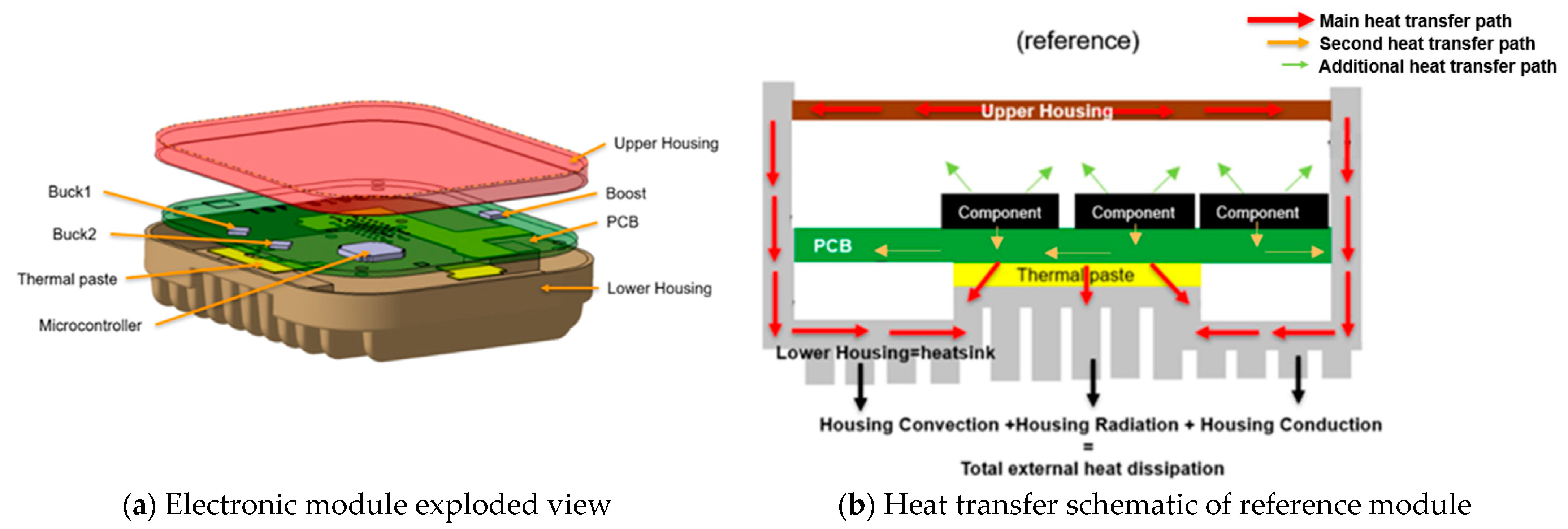
Figure 1. Schematic of (a) reference electronic module exploded view and (b) heat transfer of reference module.
Applsci 13 05310 g001
Figure 2. Dielectric liquid cooling system with forced convection.
Applsci 13 05310 g002
Figure 3. ECUs placed in a thermal chamber.
Applsci 13 05310 g003
Figure 4. Diagrams of the standardized effects: (a) normal plot and (b) Pareto chart.
Applsci 13 05310 g004
Figure 5. (a) Main effect plot for Buck1 and (b) factorial regression analysis.
Applsci 13 05310 g005
Figure 6. Optimization plot.
Applsci 13 05310 g006
Figure 7. Cube plot for Buck1 temperatures.
Applsci 13 05310 g007
Figure 8. Temperature comparison between reference modules, cooled by thermal paste and a dielectric coolant system.
Applsci 13 05310 g008
Table 1. Thermophysical properties of liquid coolant used.
Thermal
Conductivity a
[W/m·K]
Kinematic
Viscosity b
[mm2/s]
Heat
Capacity
[J/K·m3]
Density a
[kg/m3]
Specific Heat
[J/kg·K]
Coefficient of
Expansion a
[1/K]
Boiling Point
[°C]
Pour
Point
[°C]
SHC0.1368.111,659,00079021000.00067 >300−57
TIM2
a at 20 °C. b at 40 °C.
Table 2. Temperature measurements at 85 °C.
Coolant VolumeAir Flow Rate (Fan)Coolant Flow RateT_PCBT_BoostT_Buck1T_Buck2T_μC
3003.20.63105951049989
105951049989
1.54104931039789
104931039789
1.7510696.410610192
0.63108.997108102.190
10897108102.393.1
4003.2105.693105.310187.2
10693.41059989
105.893.71059988.4
1.751.54106.39810910393
106.597.4108102.193
0.6310898108103.590
108.596.6107.4103.592
11010311010698
3.21.54104.993.8103.410089.7
10493102.997.789
3501.0850.91106.2097.00106.0099.0090.00
106.8097.00106.0099.0090.00
Disclaimer/Publisher’s Note: The statements, opinions and data contained in all publications are solely those of the individual author(s) and contributor(s) and not of MDPI and/or the editor(s). MDPI and/or the editor(s) disclaim responsibility for any injury to people or property resulting from any ideas, methods, instructions or products referred to in the content.