Article

Fast Point Cloud Registration Method with Incorporation of RGB Image Information

1
Hubei Province Key Laboratory of Intelligent Robot, Wuhan Institute of Technology, Wuhan 430079, China
2
School of Mathematics and Physics, Wuhan Institute of Technology, Wuhan 430079, China
3
School of Artificial Intelligence, Hubei Business College, Wuhan 430079, China
*
Authors to whom correspondence should be addressed.
Appl. Sci. 2023, 13(8), 5161; https://doi.org/10.3390/app13085161
Submission received: 24 March 2023 / Revised: 10 April 2023 / Accepted: 17 April 2023 / Published: 20 April 2023
(This article belongs to the Special Issue Innovative Technologies in Image Processing for Robot Vision)

Abstract

:
Point cloud registration has a wide range of applications in 3D reconstruction, pose estimation, intelligent driving, heritage conservation, and digital cities. The traditional iterative closest point (ICP) algorithm has strong dependence on the initial position, poor robustness, and low timeliness. To address the above issues, a fast point cloud registration method that incorporates RGB image information is proposed. The SIFT algorithm is used to detect feature points of point clouds corresponding to the RGB image, followed by feature point matching. The RANSAC algorithm is applied to remove erroneous point pairs in order to calculate the initial transformation matrix. After applying a pass-through filter for noise reduction and transiting down with a voxel grid, the point cloud is subjected to rotation and translation transformation for initial registration. On the basis of initial alignment, the FR-ICP algorithm is utilized for achieving precise registration. This method not only avoids the problem of ICP easily getting stuck in local optima, but also has higher registration accuracy and efficiency. Experimental studies were conducted based on point clouds of automotive parts collected in real scenes, and the results showed that the proposed method has a registration error of only 0.487 mm. Among the same group of experimental point clouds with comparable registration error, the proposed method showed a speed improvement of 69%/48% compared to ICP/FR-ICP with regard to registration speed.

1. Introduction

Recently, the development of 3D laser scanning technology has been rapid. Laser scanning devices can obtain point cloud data by scanning objects [1]. Compared with 2D image data, point cloud data contain depth information and have a wider range of application scenarios. However, due to the limited field of view of laser scanning devices, point cloud registration technology is usually required to match and fuse fragmented point cloud data in applications. For example, in 3D reconstruction, point cloud data captured from different perspectives need to be registered to obtain complete point cloud data [2]; in robot grasping, point cloud registration is needed to estimate the precise pose of the workpiece [3]; in autonomous driving, point cloud registration is used to construct real-time maps and achieve high-precision positioning of the vehicle [4]; in heritage conservation, point cloud fragments are stitched together to improve the efficiency of heritage restoration while avoiding secondary damage to heritage through manual restoration [5]; in the construction of a digital city, point clouds of features obtained from multiple sites are stitched together to create a highly realistic and accurate 3D model of the urban landscape [6]. As a fundamental work, the study of point cloud registration technology has important value and broad application prospects.
The iterative closest point (ICP) algorithm [7] is the most widely used and classic algorithm for point cloud registration. It selects the points with the minimum Euclidean distance as corresponding points and obtains the optimal rigid transformation between two point cloud datasets by minimizing the distance between corresponding points in the two sets [8]. However, the ICP algorithm is highly dependent on the initial registration position and is prone to local optimal solutions [9]. At the same time, ICP has low efficiency.
To improve ICP, Yang et al. proposed the Go-ICP algorithm, which partitions the subspaces in SE(3) and removes unproductive subspaces using a branch-and-bound method to find global optimal transformation [10]. Although this method solves the problem of local minima and has certain improvements in registration accuracy and iteration speed, it is still sensitive to initialization. Pavlov et al. introduced Anderson acceleration into the ICP algorithm to accelerate the convergence of objective function and improve robustness of registration [11,12], but it still does not solve the problem of dependence on the initial position. Zhang et al. proposed a fast and robust iterative closest point (FR-ICP) algorithm [13] based on the previous work that introduced Anderson acceleration into the ICP algorithm. They used the Welsch function as the metric error and minimized its quadratic surrogate function to obtain the optimal solution. This approach not only accelerated the iteration speed but also further improved the robustness of the algorithm. However, it still cannot solve the problem of dependence on the initial position. To address the problem of dependence on initial position, some researchers have proposed methods that combine initial registration with the ICP algorithm to achieve fast registration. Li et al. proposed a point cloud registration algorithm based on ISS-SHOT features [14], which uses the ISS algorithm [15] to extract point cloud feature points and perform SHOT feature description [16]. The initial registration is completed by matching point pairs. Although this method has strong descriptiveness, it lacks robustness and easily produces erroneous point matches. Jing et al. proposed a point cloud registration method based on SIFT feature points combined with the ICP algorithm [17]. They used the scale invariant feature transform (SIFT) algorithm to extract feature points from the point cloud and calculated fast point feature histogram (FPFH) features of feature points [18]. In this method, the initial registration is completed by matching points. This method is computationally complex during feature extraction and is prone to erroneous matches. Wang et al. proposed an improved ICP algorithm [19] by introducing RGB-D point cloud color information to assist in establishing accurate point correspondence and reducing the influence of noise and outliers on registration results, thus improving the accuracy of point matching in the improved ICP algorithm. This method requires point clouds to have color information. Wang et al. also proposed an improved sample consensus point cloud registration algorithm [20]. By introducing a quadratic function of distance in FPFH, the weight of points in far-distance neighborhoods is reduced, while the weight of points in near-distance neighborhoods is increased to match corresponding points. This method makes the matching of corresponding point pairs more precise, but the efficiency is compromised.
ICP and variants mentioned above are prone to dependence on the initial position of point cloud in point cloud registration, which can lead to poor registration results. In addition, the initial registration stage of these algorithms is computationally complex [21], and will lead to erroneous matches. In order to solve these problems, a point cloud registration method that incorporates RGB images is proposed. Firstly, the SIFT algorithm is used to extract feature points from the RGB image corresponding to the point cloud, and feature point matching is performed with bidirectional KNN. The random sample consensus (RANSAC) algorithm [22] is then applied to eliminate incorrectly matched point pairs. The initial transformation matrix is calculated using four matched pairs of points based on the transformation of the coordinate system between the laser scanning device and the coaxial visible camera. The initial alignment is performed on the point cloud that has been denoised with a pass-through filter [23] and transited down the voxel grid [24]. Finally, on the basis of the initial alignment, the FR-ICP algorithm [13] can be used for precise registration. Extracting feature points from point clouds can bring about complex computation. In this work, the complexity of initial alignment is reduced by extracting feature points from the RGB image corresponding to point cloud, and using the RANSAC algorithm to eliminate incorrectly matched points, thereby reducing the computational complexity and the rate of incorrect matching.
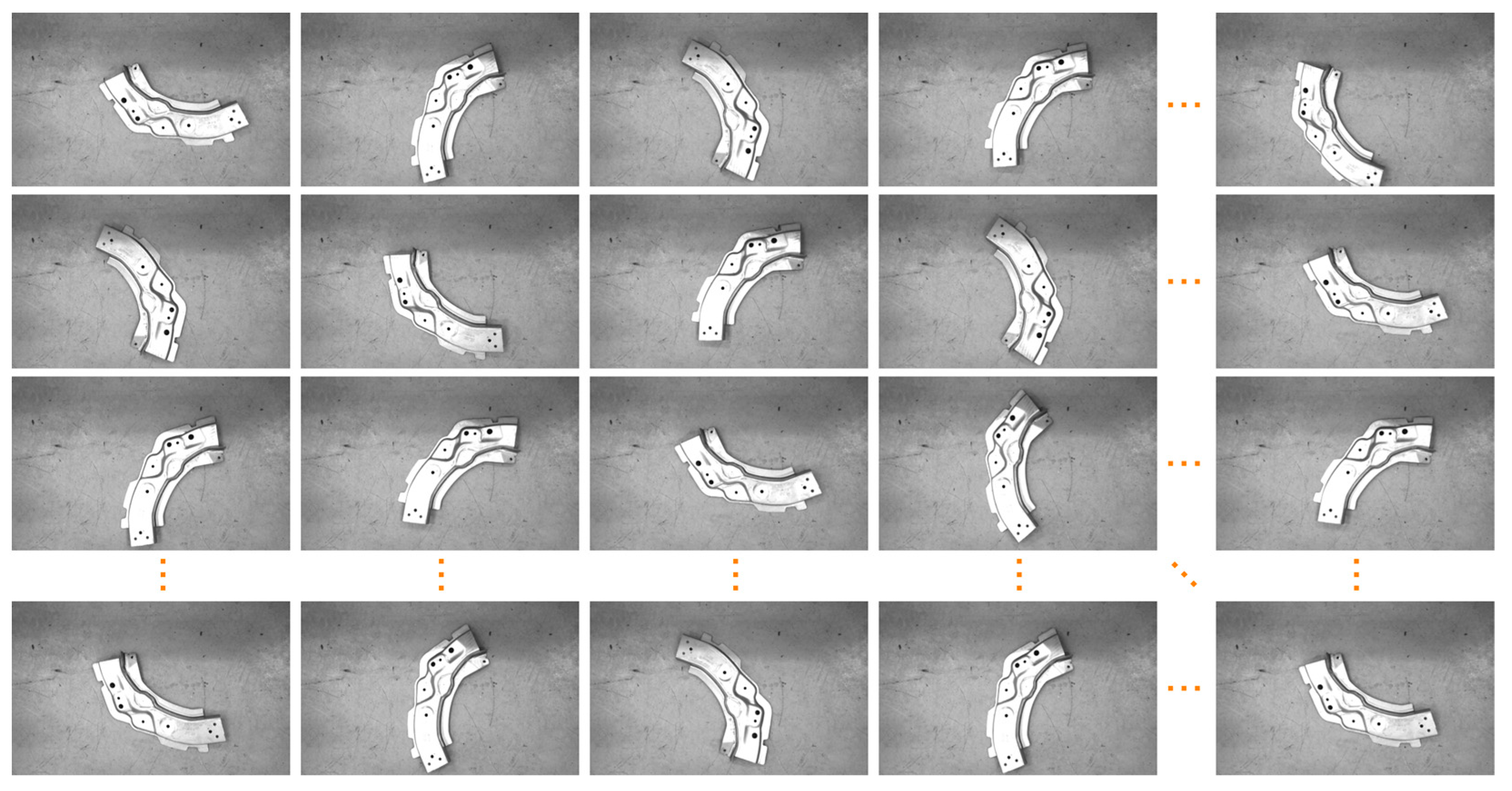
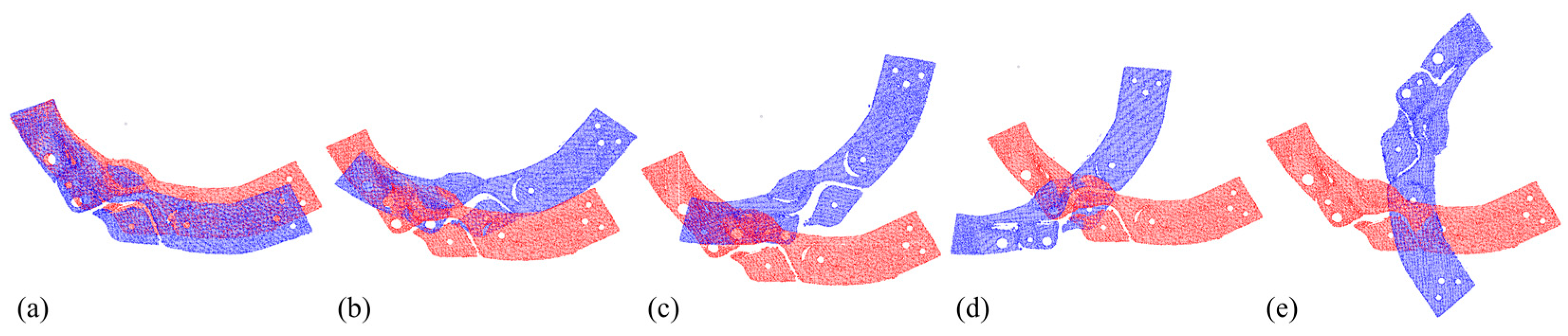
Experimental research was conducted using a point cloud dataset of automotive parts collected in real scenes, and error measurements were performed on the registered point cloud data under different initial angles. Experimental comparison and analysis were conducted with ICP and FR-ICP, and the results showed that the proposed method has a registration error of only 0.487 mm. In the same group of point cloud experiments with comparable registration error, the proposed method showed an improvement in registration speed of up to 69%/48% compared to ICP/FR-ICP.

2. Methods

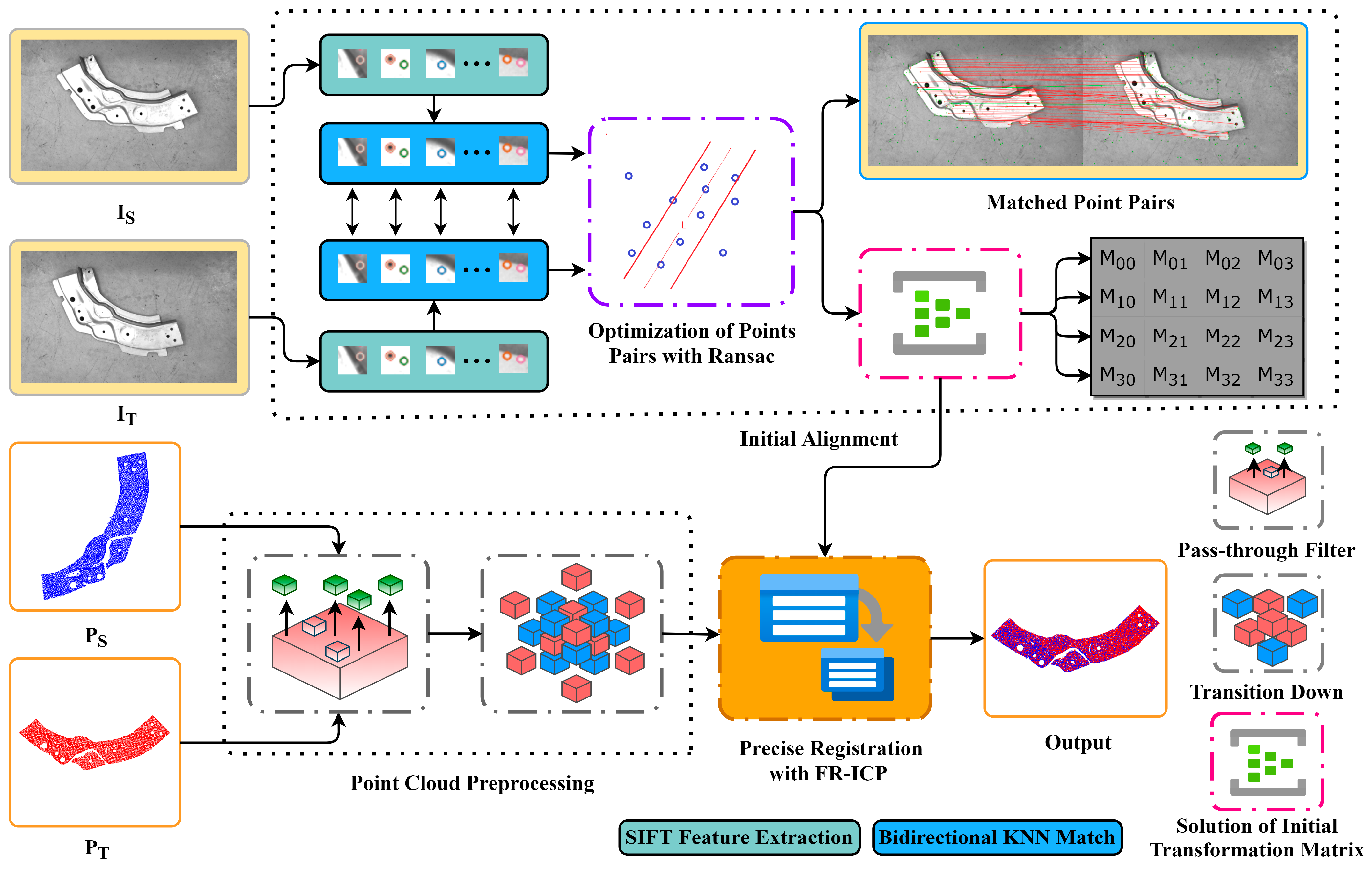
The flow of the research method proposed in this article is shown Figure 1. Firstly, SIFT algorithm was applied to detect feature points in the RGB image corresponding to the point cloud, and the feature descriptors were calculated. Then, a bidirectional KNN algorithm was used to match the feature point pairs based on their feature descriptors. The RANSAC algorithm was utilized to eliminate erroneous feature point pairs and obtain optimized feature point pairs. From the selected feature point pairs, four non-collinear pairs were chosen to solve for the homography matrix H. Based on the coordinate system transformation relationship between the laser scanning device and the coaxial visible light camera, the camera motion parameters decomposed from H were converted to the motion parameters of the point cloud laser scanning device in order to form the initial transformation matrix for point cloud registration. The initial alignment was completed by applying the initial transformation matrix to the point cloud data that had undergone noise removal through a pass-through filter and transited down the voxel grid. This resulted in a rotation and translation transformation of the point cloud data. Finally, based on the initial alignment, the improved FR-ICP algorithm using Anderson acceleration was employed for further optimization, resulting in accurate point cloud registration.

2.1. Initial Alignment Based on RGB Images

In order to address the strong dependence of ICP on the initial alignment position, in this section, our work introduces the initial alignment based on the RGB images. We detected feature points in RGB scene images with SIFT and used bidirectional KNN for feature point matching. In the subsequent sections of this section, RANSAC has been used to reduce the number of erroneous feature point pairs, and how to solve the transformation matrix for the initial alignment of the point cloud will be illustrated.

2.1.1. Extraction of Feature Points with SIFT

SIFT, SURF, and ORB are commonly used algorithms for feature point detection. However, the ORB algorithm detects feature points unevenly, lacks rotation invariance, and is sensitive to noise [25]. The SURF algorithm performs poorly in detecting feature points under lighting changes and deformation [26]. Considering the positive stability of the SIFT algorithm and its ability to adapt to rotation [27], scale changes, and brightness changes [28], our work uses SIFT to extract features from RGB images and perform initial alignment.
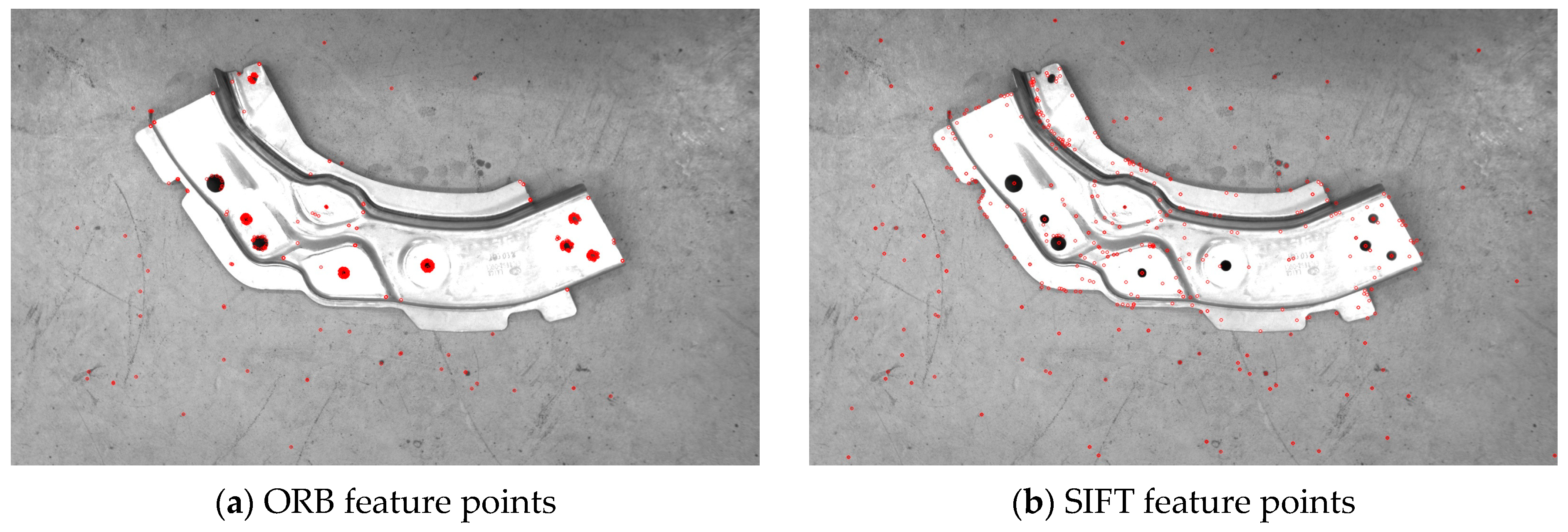
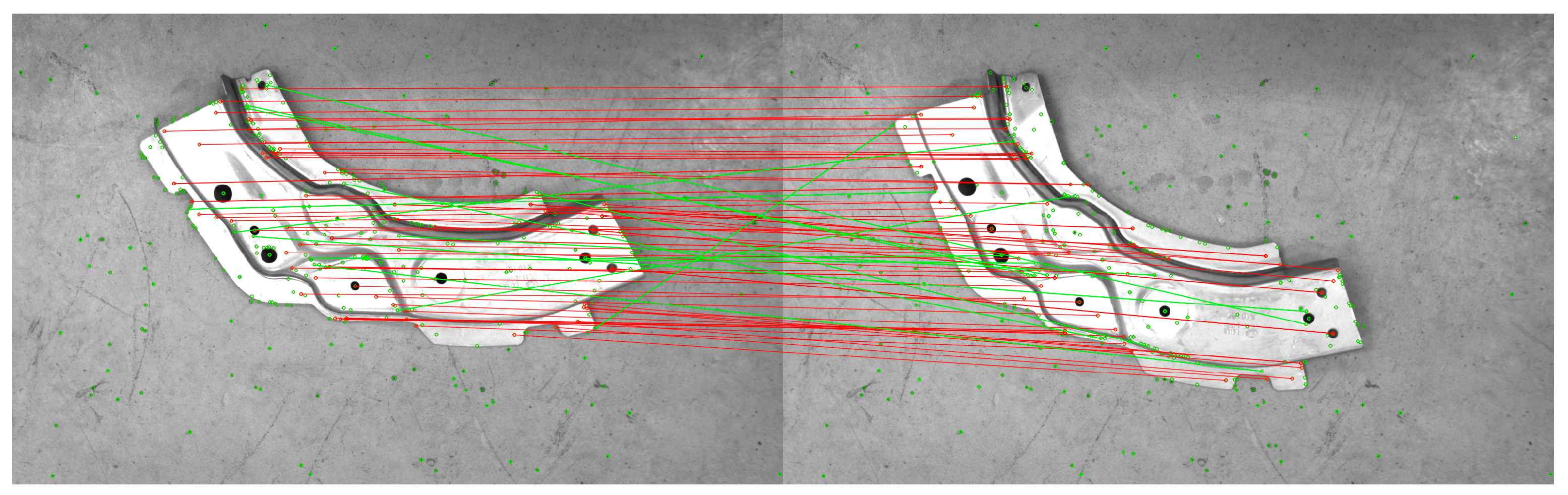
The SIFT algorithm detects the extremum in the scale space by constructing a Gaussian pyramid, determines feature points from the extremum, and forms a 128-dimensional feature descriptor. To compare the performance of different feature point detection algorithms, feature points were extracted from the RGB scene images corresponding to the experimental point cloud, and the final detection results are shown in Figure 2. The left image in Figure 2 shows the feature point extraction result of ORB on the RGB scene image, with unevenly distributed extracted features. The right image in Figure 2 shows the feature point extraction results of SIFT on the RGB scene image. The SIFT algorithm is sensitive to feature points in the image, and even if the scene object is single, it can obtain a sufficient number of feature points, which is beneficial for subsequent feature matching.

2.1.2. Feature Point Matching

Upon extraction of feature points from two RGB images, the commonly used method for matching is brute force matching. However, when the number of feature points is large, this approach can lead to a lengthy matching time and a significant number of false matches. To tackle the aforementioned issues, this paper proposes a bidirectional K-nearest neighbor (KNN) algorithm for feature point matching. Specifically, a k-d tree is constructed for both the source and target images, and KNN matching is performed independently on each of them. The common matching point pairs resulting from both matches are then obtained as the initial matching result, effectively reducing the number of false matches in the initial set.
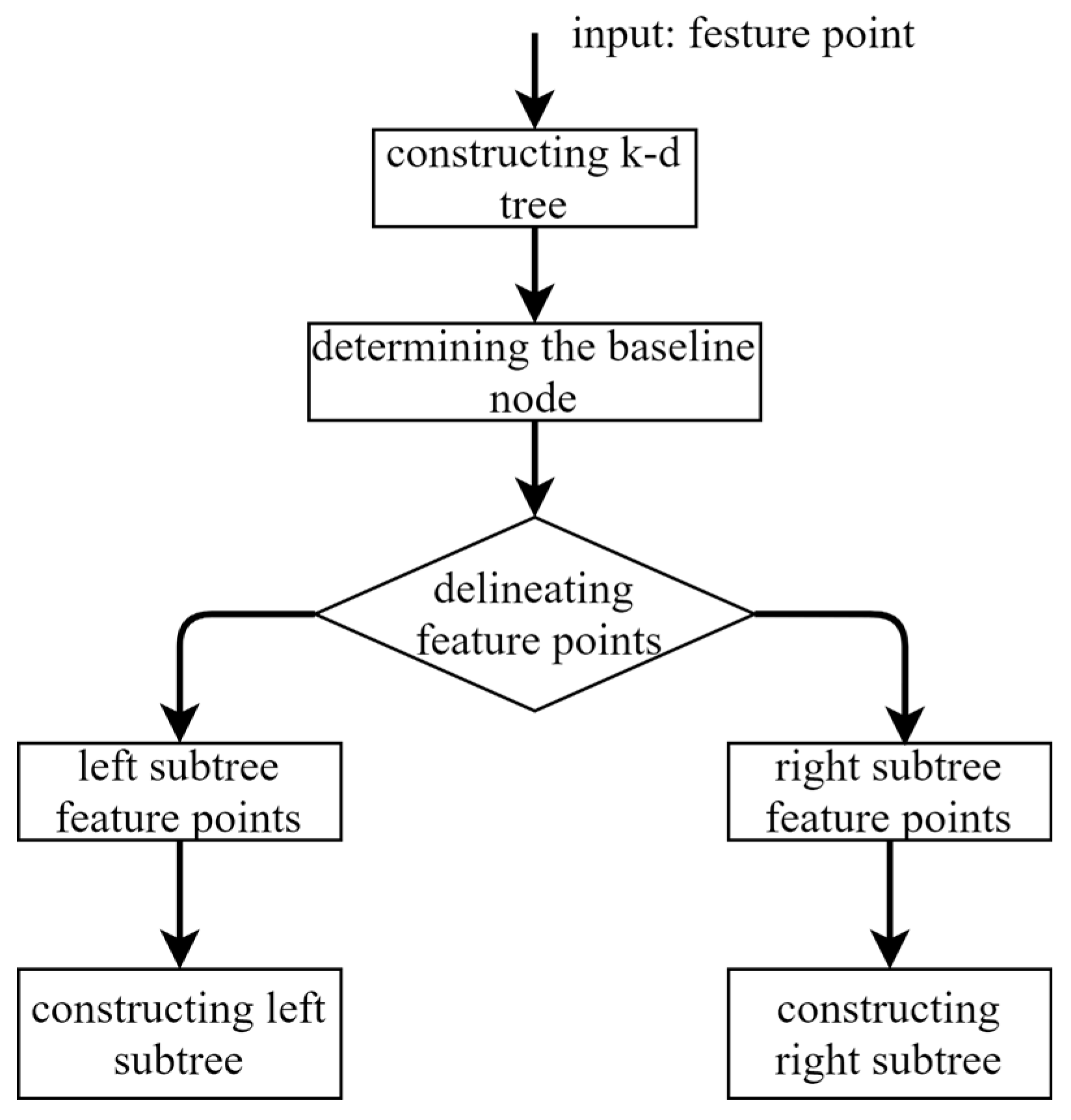
A k-d tree is constructed from the feature descriptors and the variance of X and Y dimensions is used to dimensionally segment the feature points. Afterwards, the dimension with the largest variance is sorted, and the median is taken as the pivot node. Nodes with values less than this median are assigned to the left sub-tree, while nodes with values greater than this median are assigned to the right sub-tree. This process is repeated until all nodes have been assigned. Figure 3 depicts the process of constructing a k-d tree.
Bidirectional KNN feature matching refers to the process of building k-d trees (k-d tree 1 and k-d tree 2) for both source and target images, and then searching for the k nearest neighbor feature points of the target image, starting from the root node of k-d tree 1. At the same time, this process is also performed on k-d tree 2. The similarity between each feature point and other nodes is measured by the Euclidean distance between two feature points. The smaller the ratio of the Euclidean distance between two feature points, the higher the match between the two feature points, and vice versa, the lower the match. The matching points for the current feature point are selected as the top k (k = 2) highest similarity points, and the common matching point pairs resulting from both matches are chosen as final matching result.

2.1.3. Elimination of Mismatched Pairs with RANSAC

In order to further improve the matching accuracy of the feature points, the mismatched point pairs in the matching need to be removed. In our work, the RANSAC algorithm was used to reject incorrect matching point pairs [22] and improved the matching accuracy. RANSAC uses a random sample of data as a basis for calculating the rest of the data, and by iterating over the data and reaching a threshold number of samples, a parametric model that satisfies the largest number of data points is obtained. The iteratively calculated dataset contains both correct data and abnormal data, with the correct data usually viewed as inliers and the abnormal data denoted as outliers. Noise in the data and exceptional values in the fitted model are usually regarded as outliers, and in this research outliers are represented as pairs of incorrectly matched points. The RANSAC in our research method was performed using the following steps:
(1)
Obtain sample set Q through feature point matching experiments in Section 2.1.2, and randomly select 4 pairs of corresponding points from set Q to form set S.
(2)
Use set S to calculate the homography matrix H R , denoted as model M. The method for solving the homography matrix is presented in Section 2.1.4.
(3)
Calculate the projection error between all data points in set Q and model M. If the error is less than the preset threshold T h , add the corresponding data point pair to the inner point set I. Here, X 1 and X 2 denote the matching points, the projection error can be expressed as
T h < | | X 2 H R X 1 | |
(4)
Re-randomly sample to obtain a new set S. Then, repeat steps (2) and (3). If the number of elements in the current set of interior point I is greater than the optimal set of interior points I best (where I best represents the set with the most elements), update I best = I and the number of random samples simultaneously until the number of samples reaches k (default 200).
(5)
After completing k samples, I best is selected as the dataset of the optimized feature point pairs.

2.1.4. Solution of Initial Transformation Matrix

The optimized matched pairs of feature points can be solved for the homography matrix H of the projection transformation. The initial transformation matrix of the point cloud is obtained by converting the camera motion parameters decomposed in H into the relative motion parameters of the laser scanner according to the fixed coordinate transformation relationship between the camera and the laser scanner.
Assuming that the positions of the laser scanning device and the visible camera are fixed, the coordinate systems of the laser scanning device and the camera are defined as O s x s y s z s and O c x c y c z c , respectively. The rotation parameter R h and translation parameter t h are regarded as the rigid transformation relationship between the two coordinate systems. X s and X c are considered as the coordinates under the two coordinate systems, then the transformation relationship between X s and X c is expressed as
X s = R h X c + t h
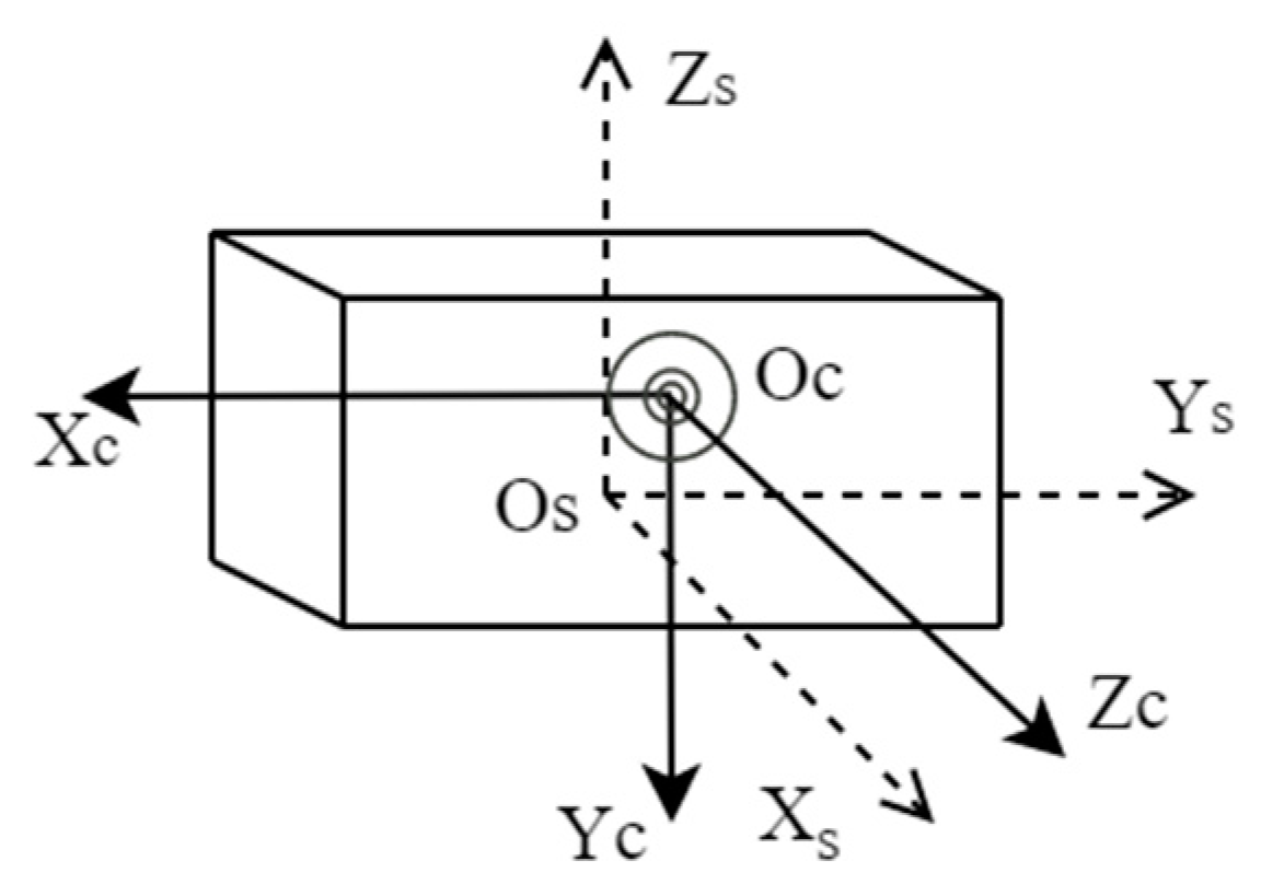
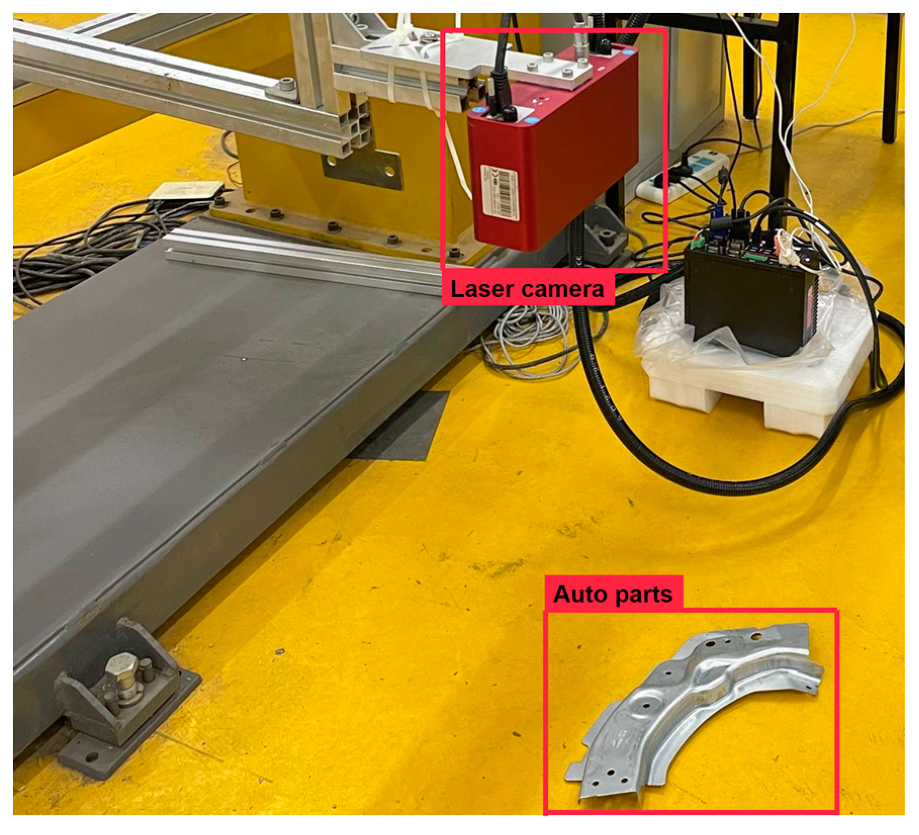
In the position shown in Figure 4 below, a conventional laser scanner is placed coaxially with the visible camera. x s and z c axes, y s and x c axes, and z s and y c axes of the coordinate system of the laser scanner and the camera coordinate system are parallel to each other, the rotation parameters between these two coordinate systems are calculated as follows:
R h = R x ( π 2 ) R y ( π 2 ) = [ 1 0 0 0 cos ( π 2 ) sin ( π 2 ) 0 sin ( π 2 ) cos ( π 2 ) ] [ cos ( π 2 ) 0 sin ( π 2 ) 0 1 0 sin ( π 2 ) 0 cos ( π 2 ) ]
The point p ( x , y ) in the RGB image captured by the camera can be transformed by projection to obtain the corresponding point p ( x , y ) in the other image, then the mapping relationship between the corresponding points of the two images can be written as
p = H × p
H is denoted as a 3 × 3 homography matrix. In H, h 33 H is a scaled free degree and constant 1, so there are 8 effective degrees of freedom. Extending the above homography matrix transformation relationship, a mapping relationship for feature point matching can be established. The matrix H with 8 degrees of freedom can be found by establishing 8 equations through 4 sets of matching points. The relative rotation parameter R c and the translation parameter t c for the camera at two positions are obtained from the SVD [29] decomposition of the matrix H.
The corresponding points in the two point clouds obtained by the laser scanning equipment are marked as X s 1 and X s 2 , and the coordinates of the two corresponding points under the camera are X c 1 and X c 2 , then the transformation of these two points under the two coordinate systems is expressed as
X s 1 = R h X c 1 + t h X s 2 = R h X c 2 + t h }
From the relative rotation parameter R c and translation parameter t c of the camera at the two positions, we have
X c 2 = R c X c 1 + λ t c
Substituting into the above two equations, we can get
X s 2 = R h R c R h 1 X s 1 R h R c R h 1 t h + λ R h t c + t h
The relative rotation parameter R and translation parameter t of the laser scanning device at two positions can be obtained as follows:
R = R h R c R h 1 t = λ R h t c + t h R h R c R h 1 t h }
Given that the scale factor λ cannot be determined, the translation parameter t can only be obtained by estimating the above equation. Using rotation parameter R and translation parameter t to form the initial transformation matrix, point cloud is rotated and translated to complete initial alignment.

2.2. Point Cloud Data Preprocessing

In the process of point cloud acquisition, point cloud data will be subject to some noise points caused by the light environment and equipment errors. In order to improve the efficiency of point cloud follow-up, preprocessing experiments of point cloud data in Section 3.1 are carried out to remove noise and transit down.

2.2.1. Pass-through Filter

The point cloud filter can eliminate some noisy points in the scene to improve the efficiency of subsequent point cloud registration. The pass-through filter, as one of the most common point cloud filters, reduces noise by eliminating values in a dimension that are not within a set threshold.
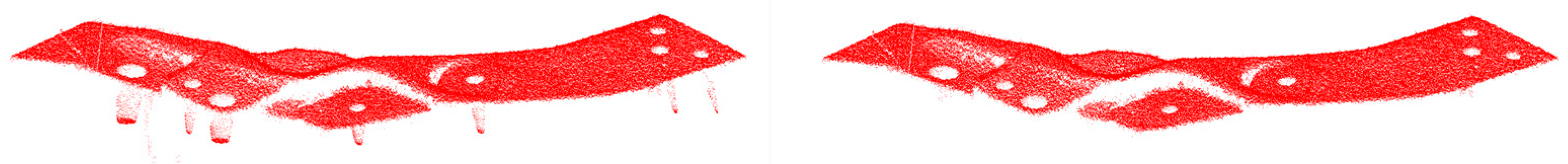
In this paper, the pass-through filter was used to eliminate the noise points on the Z-axis, and the point cloud data in this paper cover a range of [−851, −715] on the Z-axis. After several tests, the point cloud filter threshold was set to [−790, −736]. The data points outside the range were treated as noise and removed from it, and the obtained results are shown in Figure 5.
The number of points in the point cloud before noise removal was 157,551, and the number of points in the point cloud after noise removal was 153,265. After evaluation through the pass-through filter to reduce noise, the shape and position of the point cloud data do not change.

2.2.2. Transition down with Voxel Grid

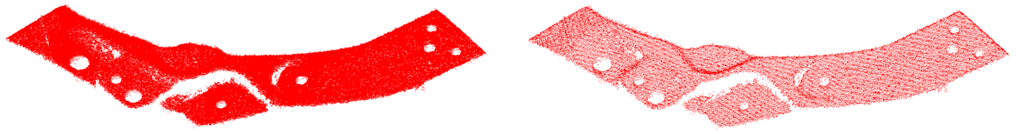
After the pass-through filter reduces the noise, the point cloud data were still relatively dense. To improve the speed of subsequent point cloud processing, the point cloud was transited down with a voxel grid. This approach can retain the basic contours and features of the point cloud, while effectively reducing the amount of point cloud data.
This process involves establishing a 3D voxel grid of the point cloud, which consists of several small grids. The data point closest to the center of gravity of the grid will be used to replace all data points, and other data points are eliminated. This approach allows for sparse data, while being simple and efficient, without the need to build complex topologies. The center of each small grid is calculated as
x c = i = 1 n x i / n y c = i = 1 n y i / n z c = i = 1 n z i / n }
In the above equation, n denotes the number of points in the small grid, and ( x i , y i , z i ) denotes the points in the small grid. The point cloud dataset in this paper is large, and a cube with a voxel volume of 1 m is created when the size of the raster is set, which here indicates the size of the voxel in the X-Y-Z direction. The results of the transition down of the point cloud with the voxel grid is reported in Figure 6.
The number of point clouds before transiting down was 153,265, and afterwards the number was 33,094. As reported in the above figure, after transiting down the point cloud, the basic contours and features are preserved. In addition, the size of the small raster can be controlled to adjust the balance between the number of point clouds and the point cloud contour information.

2.3. Accurate Registration of Point Cloud with FR-ICP

Given two sets of point cloud data P = { p 1 , , p M } and Q = { q 1 , , q N } , ICP aligns P with Q by optimizing the rigid transformations (rotation matrix R and translation matrix t ) on P :
m i n R , t i = 1 M ( D i ( R , t ) ) 2
where D i ( R , t ) = m i n q Q R p i + t q is expressed as the distance from the transformed point R p i + t to the point cloud Q . ICP solves the point cloud registration issue by alternating iterations in two steps as follows:
(1)
Correspondence step: seek the nearest corresponding point q i ^ ( k ) of p i P in Q based on the transformation ( R ( k ) , t ( k ) ) :
q i ^ ( k ) = m i n q Q R ( k ) p i + t ( k ) q
(2)
Alignment step: update the transformation by minimizing the Euclidean distance between the corresponding points:
( R ( k + 1 ) , t ( k + 1 ) ) = m i n R , t i = 1 M R p i + t q i ^ ( k ) 2
The FR-ICP algorithm uses a Welsch-based function to measure the error based on ICP, and Anderson’s accelerated majorization-minimization (MM) [30] algorithm is applied to accelerate the iteration speed of the objective function to make the error minimized. Specifically, the registration is denoted as
m i n R , t i = 1 M φ u ( D i ( R , t ) )
where φ u is the Welsch function:
φ u ( x ) = 1 e x p ( x 2 2 u 2 )
  u > 0 is a user-specified parameter. The Welsch function is used as the metric error, and its quadratic proxy function is minimized to obtain the optimal solution, and the final registration is reported as
( R ( k + 1 ) , t ( k + 1 ) ) = m i n R , t i = 1 M w i R p i + t q i ^ ( k ) 2
where ω i = e x p ( R ( k ) p i + t ( k ) q ^ i ( k ) 2 / ( 2 u 2 ) ) . This paper limits the parameter range of u with u m i n = E ¯ Q / 3 3 and u m a x = 3 D ¯ ( 0 ) , where E ¯ Q is computed as the median distances from each point q i   Q to its six nearest points on Q and D ¯ ( 0 ) is the median of all initial point-wise distances { ( R ( 0 ) , t ( 0 ) ) } .
The FR-ICP algorithm is based on minimizing the Euclidean distance between corresponding points in two sets of point sets to achieve the optimal rigid transformation between two point clouds, so there is also the problem of sensitivity to the initial position. In this paper, initial alignment and FR-ICP were used to complete the whole registration process to avoid registration failure caused by falling into the local optimum, and also to improve the efficiency of the accurate registration stage. In the accurate registration stage, the results of the initial alignment of the point cloud were treated as the input of FR-ICP. The default parameter settings of FR-ICP were used to register the two sets of points to ensure the ultimate accuracy.

3. Experiment

3.1. Experimental Dataset

The experimental dataset contained 200 point clouds of automotive parts collected in real scenes and the corresponding RGB scene images. The data acquisition scene and equipment are shown in Figure 7, where the top is the point cloud laser scanning equipment with coaxial visible light camera, specifically the ALSONTECH AT-S1000-06C-S 3D (Zhengzhou, China) visual camera. The object at bottom represents automotive parts.
The number of points in each point cloud in the experimental dataset was in the interval of [1.5 × 10⁵, 1.6 × 10⁶] and the resolution of the image data was   1920 × 1080 . The point cloud shooting scene was fixed, target point cloud was unique, and the rotation angle of the source point cloud relative to the target point cloud on the Z-axis was [ 90 ° , 90 ° ] . Figure 8 shows the RGB scene images corresponding to the experimental point clouds. To better display point cloud data, Figure 9 shows the streamlined five groups of point clouds in the experimental point clouds, where the source and target point clouds are represented as blue and red, respectively.

3.2. Experimental Environment

We report the hardware and software configurations for this work in Table 1. The results of each subsequent experiment were derived from the above configuration to provide unbiased research conclusions.

3.3. Experimental Results

3.3.1. Results of Feature Point Matching

The results of feature point matching are shown in Figure 10. The correct matching point pairs and the incorrect matching point pairs are represented as red and green, respectively. The number of total matching point pairs in the set of feature point pairs was 88 and the number of incorrect matching point pairs was 14. The final feature point matching effect of RANSAC to eliminate the mismatched point pairs is shown in Figure 11, in which the number of total matched point pairs was 76 and the number of mismatched point pairs was reduced from 14 to 2. The number of mismatched point pairs contained in the set of feature point pairs was significantly reduced, and the feasibility of the feature point matching method in this paper was verified.

3.3.2. Result of Point Cloud Preprocessing

The original point cloud contained a large amount of noise and the number of points was dense, which is not conducive to register. Table 2 shows the number of points of the five groups of point clouds to be registered in experimental data. After evaluation by the pass-through filter to reduce noise and transiting down with voxel grid, the noise points were removed from point cloud data, reducing the number of points while preserving the basic contours and features of point cloud.

3.3.3. Point Cloud Registration

To verify the effectiveness of this method, the point clouds in Section 3.1 were registered under the same experimental environment, and this method was compared with ICP and FR-ICP for analysis. In the experiments, two sets of alignment experiments of ICP were set up to measure the improvement in accuracy and speed of this method by iterating 50 times and 100 times, respectively, while keeping other parameters constant. In addition, only the initial alignment was used to measure the experimental metrics while maintaining the default parameters of FR-ICP.
The experimental evaluation metric was RMSE, which indicates the sum of squared distances from the source point cloud to the corresponding point pairs of the target point cloud, and the smaller the sum of squared distances indicates the lower registration error of the point cloud. Registration time was also compared to measure the efficiency of the registration method, where RMSE is defined as
RMSE = i = 1 M R p i + t q i 2 M
The registration results of the five sets of streamlined point clouds shown in the analysis of the experimental data are shown in Table 3, where the first column shows the five sets of streamlined point clouds to be registered, and each subsequent column shows the registration results of the ICP, FR-ICP, and our method, respectively. As can be seen from the table, the registration results of the ICP algorithm with 50 iterations on all five groups of point clouds showed significant deviations and fell into local optimum when registering the point cloud in Table 3e with the largest rotation angle, resulting in registration failure. When the number of iterations of ICP reached 100, registration improved, but registration failure still occurred in the results. In the registration results of five sets of point clouds, our method and FR-ICP had good registration performance, which was due to the fact that the initial alignment in this paper kept good initial positions between the point clouds to be registered and prevented the point clouds from falling into local optimum in the alignment.
The registration results of the above five groups of point clouds were evaluated metrically, and the RMSE and speed of the registration experiments were compared, as shown in Table 4. The table shows the higher registration error of ICP in the above point clouds. Without considering the alignment failure, the RMSE of the point cloud in d reached 1.721/0.834, and ICP compromised the speed while improving the accuracy. In d, the accuracy of our method improved from 0.834 mm of ICP (iter 100) to 0.580, and the speed increased by 42%. Compared with FR-ICP, our method had equal accuracy and outperformed FR-ICP in terms of speed, due to the fact that our method had a better initial position at registration, which reduced the computational overhead in the fine registration stage. With comparable accuracy in a, the 18.87 s of our method compared to 61.84 s/36.75 s of ICP (iter 100)/FR-ICP, the improvement in speed reached 69%/48%. Based on the above observations, we can conclude that our method can solve the problem of point cloud registration easily falling into local optimum, and has advantages in speed and accuracy compared with traditional methods.

4. Conclusions

In this work, we report a fast point cloud registration method incorporating RGB image information to solve the problems of strong dependence on the initial position of the point cloud, poor robustness, and low timeliness of ICP. In the proposed method, the SIFT algorithm is used to extract the feature points of point cloud corresponding to the RGB image and to perform feature point matching with bidirectional KNN. The RANSAC algorithm is used to reject mismatched points and calculate the initial transformation matrix. After applying the pass-through filter for noise reduction and transiting down the voxel grid, the point cloud is subjected to rotation and translation transformation for initial registration. On the basis of the initial registration, the FR-ICP algorithm is utilized for achieving accurate registration. The results, analyzed by registration experiments, showed that our method can solve the problem that point cloud registration easily falls into local optimum, and has advantages in speed and accuracy compared with traditional methods. This work relied on the visible camera of laser equipment to provide some reference for the point cloud acquired by such equipment in the registration work. Nevertheless, it is worth noting that the SIFT algorithm takes some time in extracting feature points. Meanwhile the RANSAC algorithm still suffers from some instability in rejecting incorrect feature point pairs, and only most of the incorrect point pairs could be rejected in our work. Some improved versions of RANSAC, such as some probabilistic versions of RANSACs [31], are available for use in subsequent research work. All these potential problems above will be the direction of further research in the future.

Author Contributions

Conceptualization, Z.Z. and J.J.; project administration, Y.Z.; supervision, D.C., Z.Z. and H.Z.; validation, H.Z.; writing—original draft, H.C.; writing—review and editing, H.C. and D.C. All authors have read and agreed to the published version of the manuscript.

Funding

This work was supported in part by the National Natural Science Foundation of China (No. 62171327, No. 62171328), the General Project of Hubei Natural Science Foundation (No. 2022CFB529), the Science and Technology Research Project of Hubei Education Department (No. B2022056), the Science Research Project of Wuhan Institute of Technology (No. K2021083), and the Graduate Innovative Fund of Wuhan Institute of Technology (No. CX2022344).

Institutional Review Board Statement

Not applicable.

Informed Consent Statement

Not applicable.

Data Availability Statement

The authors can provide the raw data of this work, upon reasonable request.

Conflicts of Interest

The authors declare no conflict of interest.

References

  1. Li, J.; Zhan, J. Review on 3D point cloud registration method. J. Image Graph. 2022, 27, 349–367. [Google Scholar]
  2. Li, A.; Luo, W.; Liu, X.; Deng, Z. 3D Reconstruction of Array Virtual Camera. Laser Optoelectron. Prog. 2022, 59, 1415013. [Google Scholar]
  3. Xu, J.; Liu, N.; Li, D.; Lin, L.; Wang, G. A Grasping Poses Detection Algorithm for Industrial Workpieces Based on Grasping Cluster and Collision Voxels. Robot 2022, 44, 153–166. [Google Scholar]
  4. Dang, X.; Qin, F.; Bu, X.; Liang, X. A robust perception algorithm based on a radar and LiDAR for intelligent driving. J. Radars 2021, 10, 622–631. [Google Scholar]
  5. Zhang, Y.; Geng, G.; Wei, X.; Zhang, J.; Zhuo, M. Reassembly of Fractured Fragments Based on Skeleton Graphs Matching. Acta Autom. Sin. 2017, 43, 622–633. [Google Scholar]
  6. Liu, K.; Fan, T.; Yang, J.; Chen, H.; Bao, G. Acquisition of urban digital surface data based on mobile measurement technology in complex environments. Bull. Surv. Mapp. 2017, 6, 165–166. [Google Scholar]
  7. Besl, P.J.; McKay, N.D. A method for registration of 3-D shapes. IEEE Trans. Pattern Anal. Mach. Intell. 1992, 14, 239–256. [Google Scholar] [CrossRef]
  8. Huang, X.; Mei, G.; Zhang, J. Feature-metric registration: A fast semi-supervised approach for robust point cloud registration without correspondences. In Proceedings of the IEEE/CVF Conference on Computer Vision and Pattern Recognition, Seattle, WA, USA, 13–19 June 2020; pp. 11366–11374. [Google Scholar]
  9. Fang, L.; Shen, G.; You, Z.; Guo, Y.; Fu, H.; Zhao, Z.; Chen, C. A joint network of point cloud and multiple views for roadside objects recognition from mobile laser point clouds. Acta Geod. Cartogr. Sin. 2021, 50, 1558–1573. [Google Scholar]
  10. Yang, J.; Li, H.; Jia, Y. Go-icp: Solving 3d registration efficiently and globally optimally. In Proceedings of the IEEE International Conference on Computer Vision, Sydney, Australia, 1–8 December 2013; pp. 1457–1464. [Google Scholar]
  11. Zheng, Z.; Zheng, H.; Ju, J.; Chen, D.; Li, X.; Guo, Z.; You, C.; Lin, M. A system for identifying an anti-counterfeiting pattern based on the statistical difference in key image regions. Expert Syst. Appl. 2021, 183, 115410. [Google Scholar] [CrossRef]
  12. Pavlov, A.L.; Ovchinnikov, G.W.; Derbyshev, D.Y.; Tsetserukou, D.; Oseledets, I.V. AA-ICP: Iterative closest point with Anderson acceleration. In Proceedings of the 2018 IEEE International Conference on Robotics and Automation (ICRA), Brisbane, QLD, Australia, 21–25 May 2018; pp. 3407–3412. [Google Scholar]
  13. Zhang, J.; Yao, Y.; Deng, B. Fast and robust iterative closest point. IEEE Trans. Pattern Anal. Mach. Intell. 2021, 44, 3450–3466. [Google Scholar] [CrossRef]
  14. Li, Y.; Guo, J.; Pan, S.; Lv, L.; Lu, Z.; Zhang, D. A point cloud registration algorithm based on ISS-SHOT features. Bull. Surv. Mapp. 2020, 4, 21. [Google Scholar] [CrossRef]
  15. Sun, R.; Zhang, E.; Mu, D.; Ji, S.; Zhang, Z.; Liu, H.; Fu, Z. Optimization of the 3D Point Cloud Registration Algorithm Based on FPFH Features. Appl. Sci. 2023, 13, 3096. [Google Scholar] [CrossRef]
  16. Liu, S.; Zheng, W.; Lin, Y. Adaptive binary simplification method for 3D feature descriptor. J. Comput. Appl. 2021, 41, 2062. [Google Scholar]
  17. Jing, L.; Wu, B.; Fang, X. Point cloud registration method based on the SIFTfeature points combined with ICP algorithm. Laser Infrared 2021, 51, 944–950. [Google Scholar]
  18. Rusu, R.B.; Blodow, N.; Beetz, M. Fast point feature histograms (FPFH) for 3D registration. In Proceedings of the 2009 IEEE international conference on robotics and automation, Kobe, Japan, 12–17 May 2009; pp. 3212–3217. [Google Scholar]
  19. Wang, L.; Guo, J.; Zhang, P.; Teng, W.; Cheng, L.; Shaoyi, D. Rigid registration method of 3D point cloud based on improved ICP algorithm. J. Northwest Univ. (Nat. Sci. Ed.) 2021, 51, 183–190. [Google Scholar]
  20. Wang, Y.; Zhuang, Z.; Xing, N. Improved sampling consistent point cloud registration algorithm. Comput. Eng. Des. 2022, 43, 1382–1388. [Google Scholar]
  21. Zhu, L.; Liu, D.; Lin, C.; Yan, R.; Gómez-Fernández, F.; Yang, N.; Feng, Z. Point cloud registration using representative overlapping points. arXiv 2021, arXiv:2107.02583. [Google Scholar]
  22. Fischler, M.A.; Bolles, R.C. Random sample consensus: A paradigm for model fitting with applications to image analysis and automated cartography. Commun. ACM 1981, 24, 381–395. [Google Scholar] [CrossRef]
  23. Li, Y.; Luo, Y.; Pu, Q.; Mingfei, H.; Feng, S. A method for ground filtering of laser point cloud and extraction of tunnel wall and target sphere. Chin. J. Lasers 2022, 1–20. [Google Scholar]
  24. Liang, A.; Li, Z.; Hua, H. PointMLP-FD: A point cloud classification model based on multi-level adaptive downsampling. J. Graph. 2023, 44, 112–119. [Google Scholar]
  25. Li, G.; Xu, Y.; Duan, J.; Han, S. ORB-SLAM method based on local adaptive threshold extraction feature points. Bull. Surv. Mapp. 2021, 50, 32–36, 48. [Google Scholar]
  26. Bay, H.; Ess, A.; Tuytelaars, T.; Van Gool, L. Speeded-up robust features (SURF). Comput. Vis. Image Underst. 2008, 110, 346–359. [Google Scholar] [CrossRef]
  27. Zheng, Z.; Xu, B.; Ju, J.; Guo, Z.; You, C.; Lei, Q.; Zhang, Q. Circumferential local ternary pattern: New and efficient feature descriptors for anti-counterfeiting pattern identification. IEEE Trans. Inf. Forensics Secur. 2022, 17, 970–981. [Google Scholar] [CrossRef]
  28. Xu, Y.; Boerner, R.; Yao, W.; Hoegner, L.; Stilla, U. Pairwise coarse registration of point clouds in urban scenes using voxel-based 4-planes congruent sets. ISPRS J. Photogramm. Remote Sens. 2019, 151, 106–123. [Google Scholar] [CrossRef]
  29. Sorkine-Hornung, O.; Rabinovich, M. Least-squares rigid motion using svd. Computing 2017, 1, 1–5. [Google Scholar]
  30. Lange, K. MM Optimization Algorithms; Society for Industrial and Applied Mathematics: Philadelphia, PA, USA, 2016. [Google Scholar]
  31. Jia, S.; Wang, K.; Li, X.; Xu, T. A novel improved probability-guided RANSAC algorithm for robot 3D map building. J. Sens. 2016, 2016, 3243842. [Google Scholar] [CrossRef]
Figure 1. The overall methodological flow of this work. RGB image input source I s and target I T are applied to initial alignment, P s and P T are represented as the source and target point clouds.
Applsci 13 05161 g001
Figure 2. The performance of feature point extraction using SIFT and ORB.
Applsci 13 05161 g002
Figure 3. Construction of k-d trees.
Applsci 13 05161 g003
Figure 4. Coordinate conversion relationship between laser scanning equipment and camera.
Applsci 13 05161 g004
Figure 5. Results of point cloud pass-through filter.
Applsci 13 05161 g005
Figure 6. Results of transition down with voxel grid.
Applsci 13 05161 g006
Figure 7. Data collection scenarios and equipment.
Applsci 13 05161 g007
Figure 8. RGB scene image data corresponding to the point cloud.
Applsci 13 05161 g008
Figure 9. Five sets of streamlined example point clouds in the experimental point cloud (ae), where the source and target point clouds are represented in blue and red, respectively.
Applsci 13 05161 g009
Figure 10. The set of matched feature points.
Applsci 13 05161 g010
Figure 11. Optimized set of feature point pairs.
Applsci 13 05161 g011
Table 1. Experimental environment.
Hardware and Software Configuration
OSWindows 10
CPUIntel(R) Core(TM) i5-7300HQ CPU @ 2.50 GHz
GPUNVIDIA GeForce GTX1050
Compiling environmentVisual Studio2017, C++, PCL1. 8. 1
Table 2. Number of points in the point cloud of the 5 sets of instances after preprocessing.
Point Cloud Number of Points
Original Point CloudPass-through FilterTransition Down of Voxel Grid
Source Point Cloud157,551153,26533,094
157,026155,08232,537
156,963153,18532,137
157,595151,69531,328
158,657157,28533,130
Target Point Cloud *158,032154,90532,735
* Target point cloud unique in the experiment.
Table 3. The registration results using various methods on 5 sets of example point clouds, with RMSE (× 10 3 ) and computation time (in seconds) shown below.
Original DataICP (Iter 50)ICP (Iter 100)FR-ICPOurs
Applsci 13 05161 i001Applsci 13 05161 i002Applsci 13 05161 i003Applsci 13 05161 i004Applsci 13 05161 i005
(a)0.808, 31.82 s0.518, 61.84 s0.488, 36.75 s0.487, 18.87 s
Applsci 13 05161 i006Applsci 13 05161 i007Applsci 13 05161 i008Applsci 13 05161 i009Applsci 13 05161 i010
(b)1.092, 32.16 s0.627, 62.29 s0.556, 33.71 s0.532, 21.04 s
Applsci 13 05161 i011Applsci 13 05161 i012Applsci 13 05161 i013Applsci 13 05161 i014Applsci 13 05161 i015
(c)1.523, 32.74 s0.807, 62.36 s0.591, 41.49 s0.591, 28.39 s
Applsci 13 05161 i016Applsci 13 05161 i017Applsci 13 05161 i018Applsci 13 05161 i019Applsci 13 05161 i020
(d)1.721, 32.68 s0.834, 63.08 s0.580, 56.17 s0.580, 36.51 s
Applsci 13 05161 i021Applsci 13 05161 i022Applsci 13 05161 i023Applsci 13 05161 i024Applsci 13 05161 i025
(e)27.067, 41.19 s26.972, 79.26 s0.575, 46.70 s0.575, 32.07 s
Table 4. RMSE (× 10 3 ) and computation time (in seconds) for different registration methods on 5 sets of example point clouds.
Original DataICP (Iter 50)ICP (Iter 100)FR-ICPOurs
RMSETimeRMSETimeRMSETimeRMSETime
(a)0.80831.820.51861.840.48836.750.48718.87
(b)1.09232.160.62762.290.55633.710.53221.04
(c)1.52332.740.80762.360.59141.490.59128.39
(d)1.72132.680.83463.080.58056.170.58036.51
(e)27.06741.1926.97279.260.57546.700.57532.07
The best performance figures are highlighted in bold fonts.
Disclaimer/Publisher’s Note: The statements, opinions and data contained in all publications are solely those of the individual author(s) and contributor(s) and not of MDPI and/or the editor(s). MDPI and/or the editor(s) disclaim responsibility for any injury to people or property resulting from any ideas, methods, instructions or products referred to in the content.

