
Work Function, Sputtering Yield and Microhardness of an Al-Mg Metal-Matrix Nanostructured Composite Obtained with High-Pressure Torsion


 , ,
, ,  , ,
, ,
Abstract
1. Introduction
2. Materials and Methods
3. Results and Discussion
3.1. Microstructure and Phase Characterization of the HPT Processed Composite
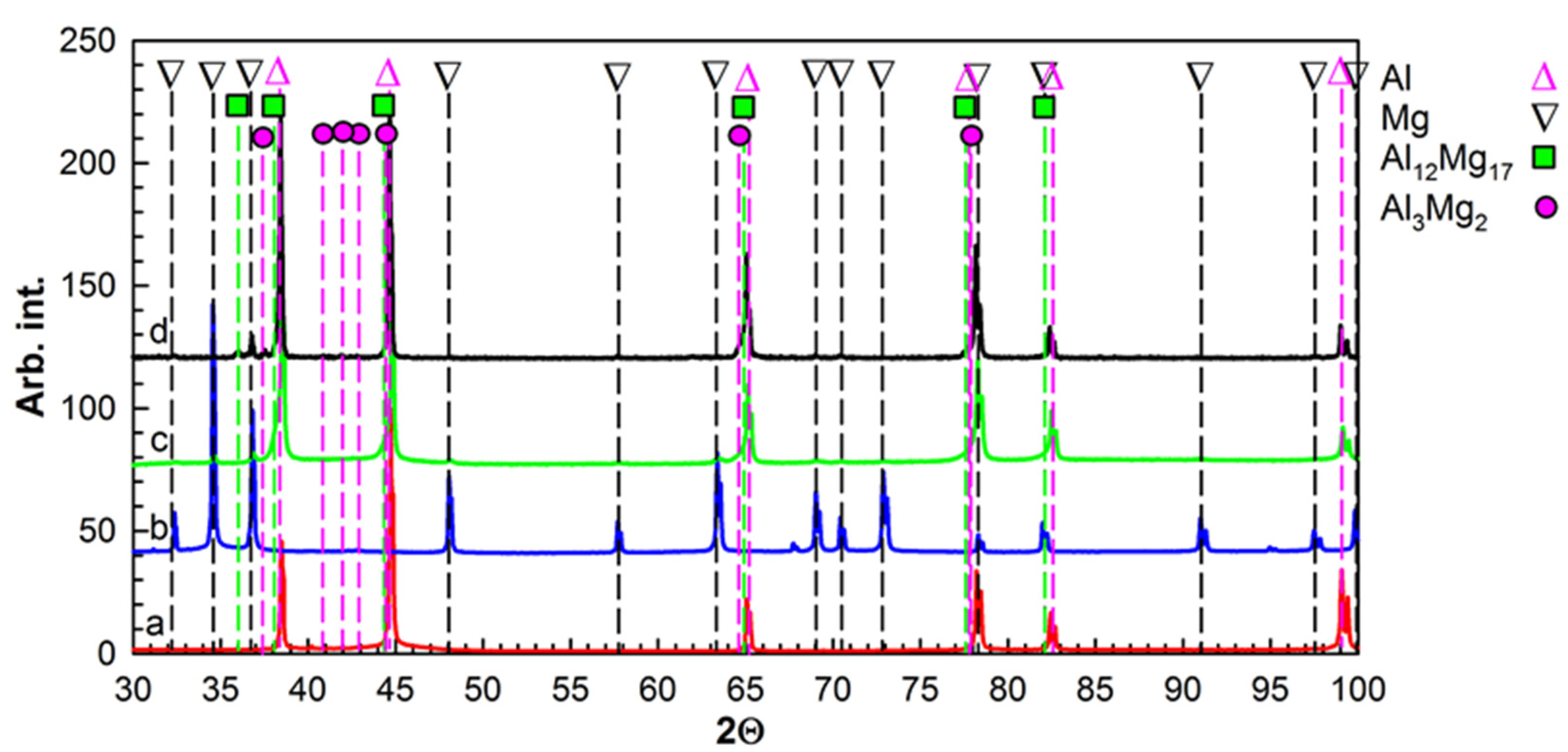
3.1.1. XRD
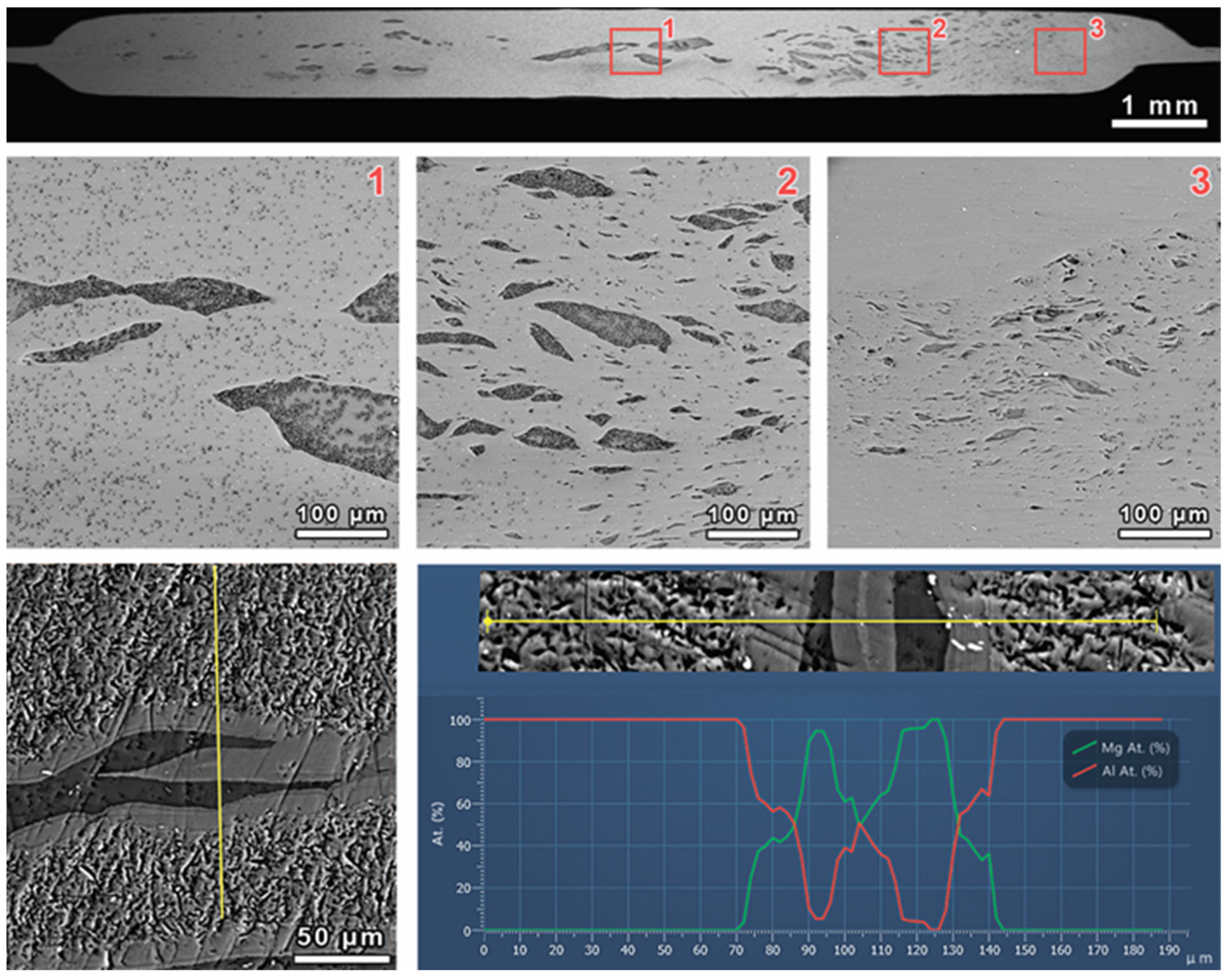
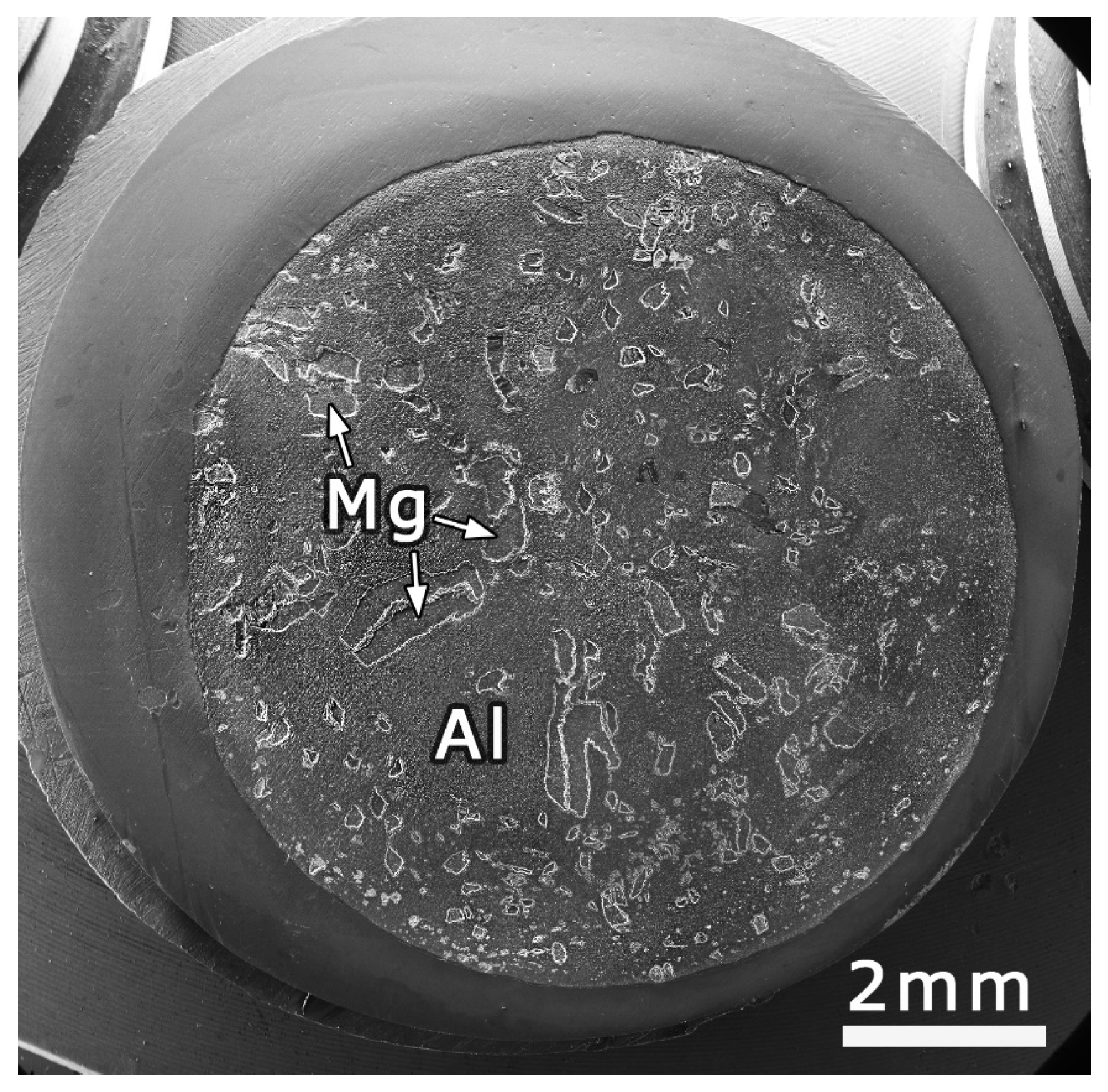
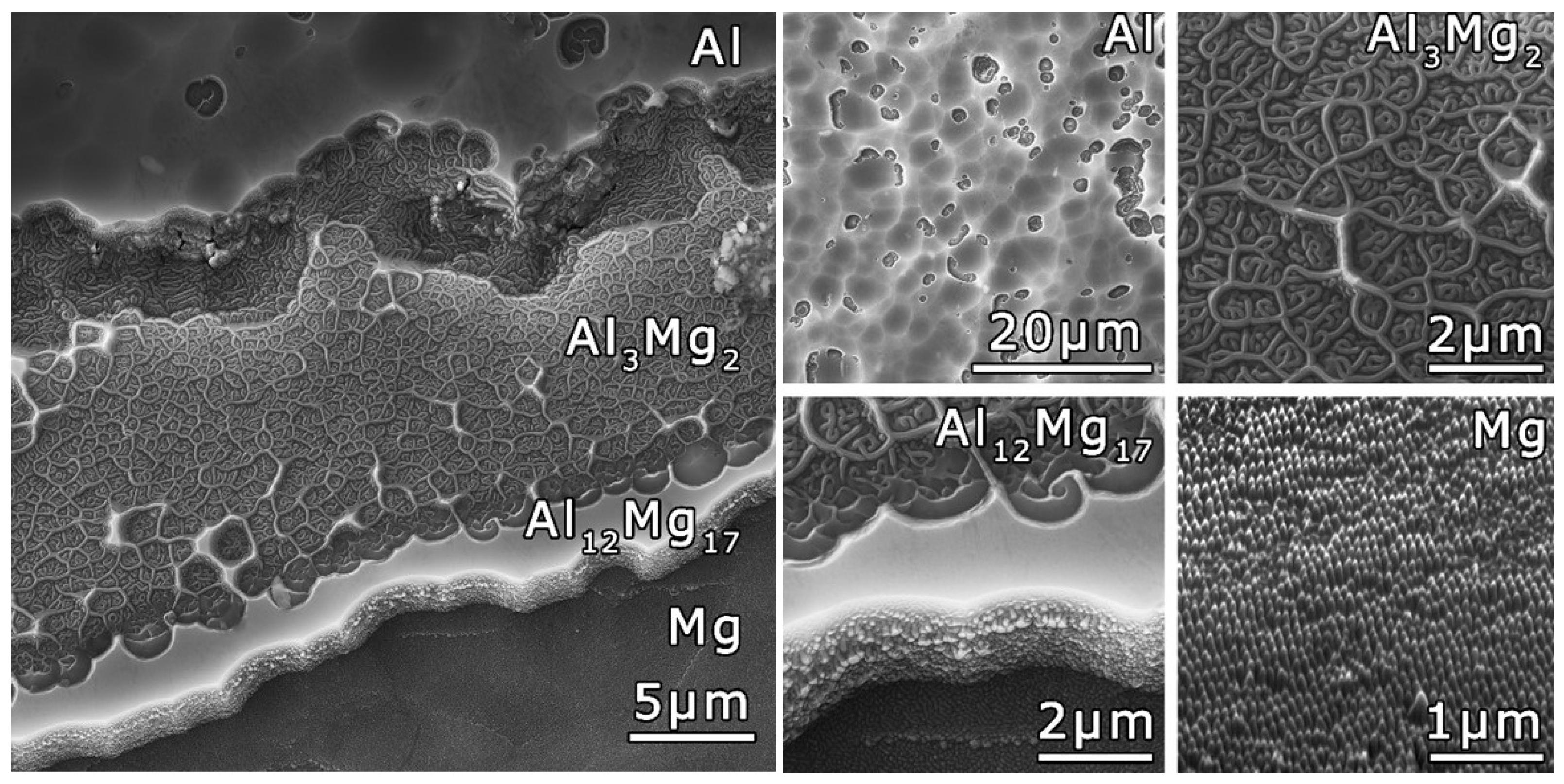
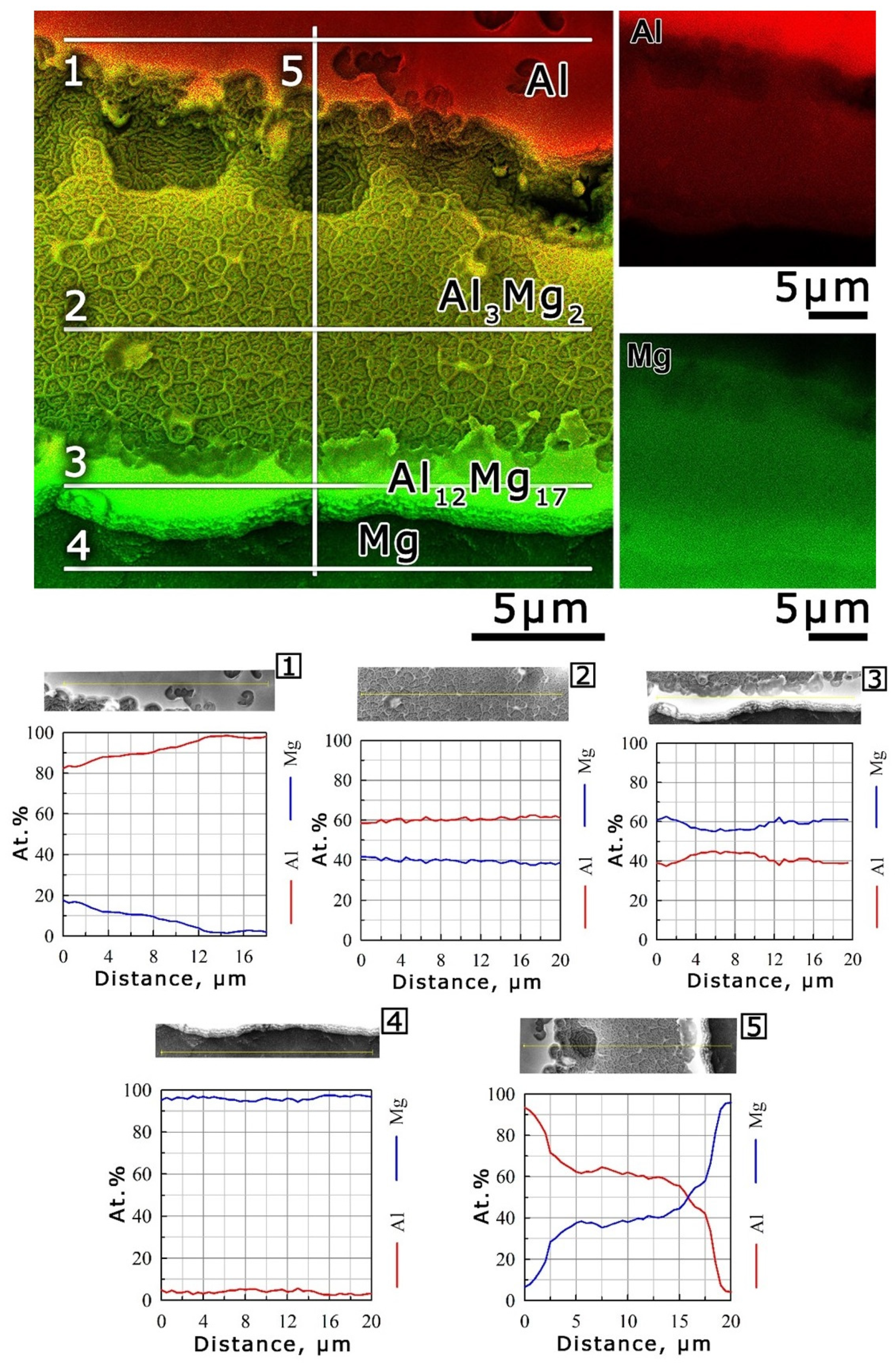
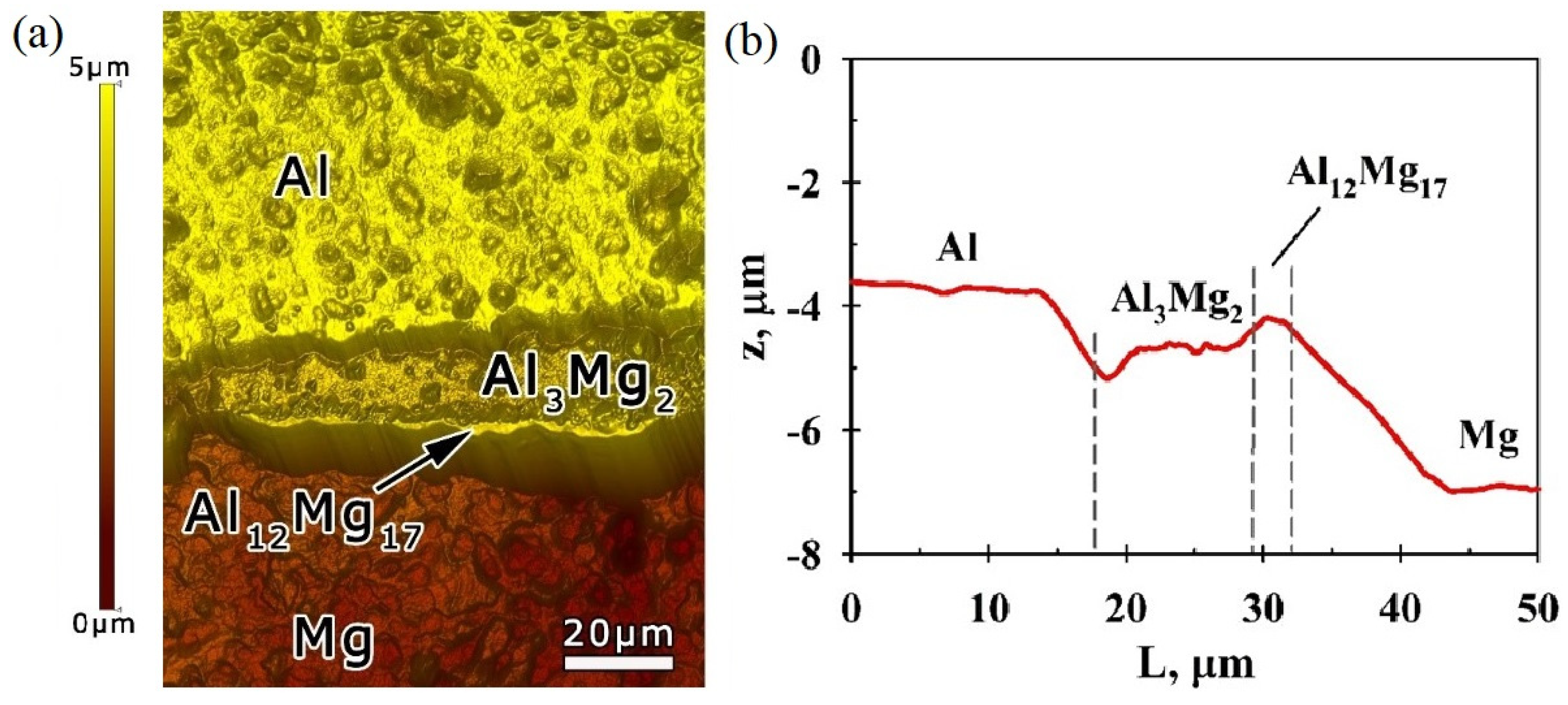
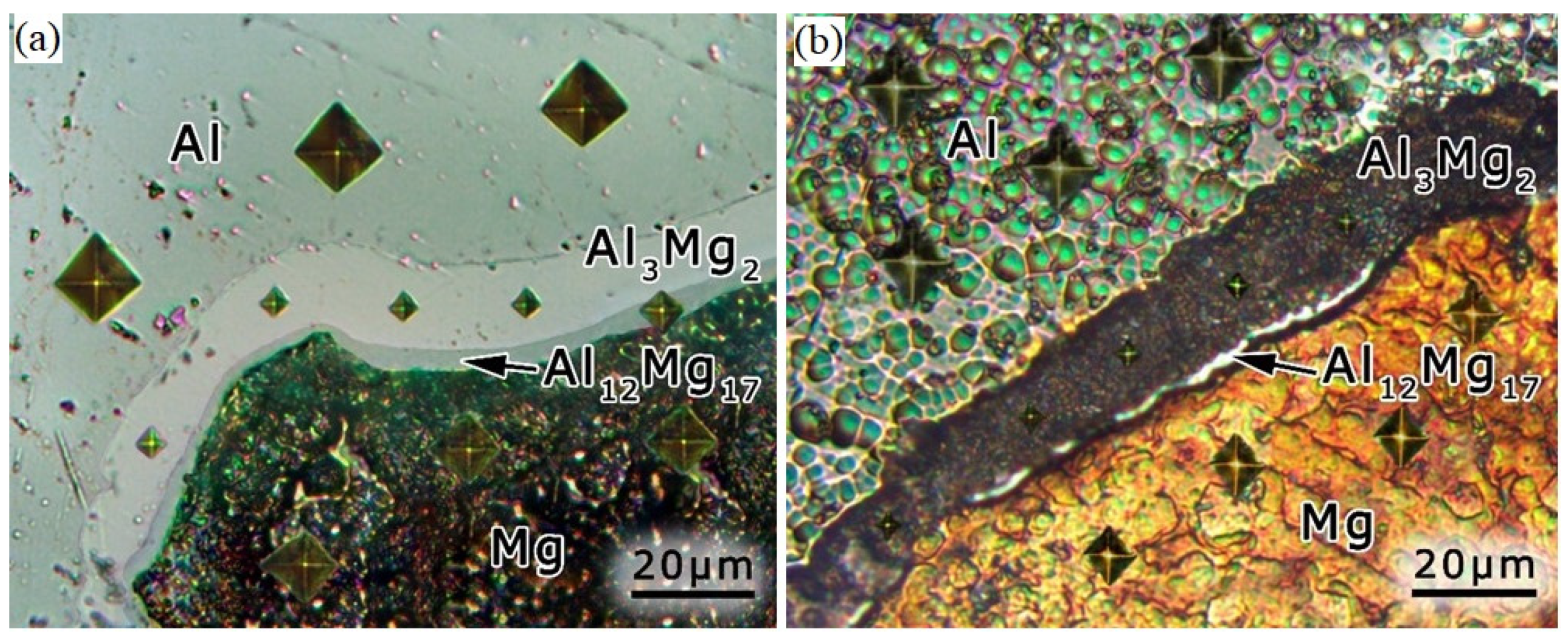
3.1.2. SEM Analysis
3.2. WF Measurements
3.3. WF Calculations
3.4. Surface Structure Modification as a Result of Ion Irradiation
3.5. Sputtering Yield Evaluations
3.6. Microhardness Measurements
4. Conclusions
Author Contributions
Funding
Institutional Review Board Statement
Informed Consent Statement
Data Availability Statement
Acknowledgments
Conflicts of Interest
References
- Wang, J.; Niu, L.; Zhang, Y.; Chen, J.; Jiang, J.; Song, D.; Li, B.; Ying, G.; Cheng, J.; Ma, A. Is Mg17Al12 ductile or brittle? A theoretical insight. J. Magnes. Alloy. 2021. [Google Scholar] [CrossRef]
- Zhang, Q.; Zhu, Y.; Gao, X.; Wu, Y.; Hutchinson, C. Training high-strength aluminum alloys to withstand fatigue. Nat. Commun. 2020, 11, 5198. [Google Scholar] [CrossRef]
- Nishimura, K.; Imai, K.; Matsuda, K.; Nunomura, N.; Tsuchiya, T.; Isikawa, Y.; Adachi, H.; Hutchison, W.D. Magnetic property of Al-Mg alloys and intermetallic compounds. J. Alloys Compd. 2021, 877, 160226. [Google Scholar] [CrossRef]
- Thakur, A.; Kaya, S.; Kumar, A. Recent Trends in the Characterization and Application Progress of Nano-Modified Coatings in Corrosion Mitigation of Metals and Alloys. Appl. Sci. 2023, 13, 730. [Google Scholar] [CrossRef]
- Kazakov, A.M.; Yakhin, A.V.; Karimov, E.Z.; Babicheva, R.I.; Kistanov, A.A.; Korznikova, E.A. Effect of Segregation on Deformation Behaviour of Nanoscale CoCrCuFeNi High-Entropy Alloy. Appl. Sci. 2023, 13, 4013. [Google Scholar] [CrossRef]
- Bihari, B.; Singh, A.K. An Overview on Different Processing Parameters in Particulate Reinforced Metal Matrix Composite Fabricated by Stir Casting Process. IJERA 2017, 7, 42–48. [Google Scholar] [CrossRef]
- Mehr, V.Y.; Toroghinejad, M.R.; Rezaeian, A. Mechanical properties and microstructure evolutions of multilayered Al–Cu composites produced by accumulative roll bonding process and subsequent annealing. Mater. Sci. Eng. 2014, 601, 40–47. [Google Scholar] [CrossRef]
- Fronczek, D.; Chulist, R.; Litynska-Dobrzynska, L.; Kac, S.; Schell, N.; Kania, Z.; Szulc, Z.; Wojewoda-Budka, J. Microstructure and kinetics of intermetallic phase growth of three-layered A1050/AZ31/A1050 clads prepared by explosive welding combined with subsequent annealing. Mater. Des. 2017, 130, 120–130. [Google Scholar] [CrossRef]
- Keiichiro, O.; Edalati, K.; Kim, H.S.; Hono, K.; Horita, Z. High-pressure torsion for enhanced atomic diffusion and promoting solid-state reactions in the aluminum–copper system. Acta Mater. 2013, 61, 3482–3489. [Google Scholar] [CrossRef]
- Korznikova, E.A.; Mironov, S.Y.; Korznikov, A.V.; Zhilyaev, A.P.; Langdon, T.G. Microstructural evolution and electro-resistivity in HPT nickel. Mater. Sci. Eng. 2012, 556, 437–445. [Google Scholar] [CrossRef]
- Bouaziz, O.; Kim, H.S.; Estrin, Y. Architecturing of Metal-Based Composites with Concurrent Nanostructuring: A New Paradigm of Materials Design. Adv. Eng. Mater. 2013, 15, 336. [Google Scholar] [CrossRef]
- Zhilyaev, A.; Langdon, T. Using high-pressure torsion for metal processing: Fundamentals and applications. Prog. Mater. Sci. 2008, 53, 893–979. [Google Scholar] [CrossRef]
- Mulyukov, R.R.; Korznikova, G.F.; Nazarov, K.S.; Khisamov, R.K.; Sergeev, S.N.; Shayachmetov, R.U.; Khalikova, G.R.; Korznikova, E.A. Annealing-induced phase transformations and hardness evolution in Al–Cu–Al composites obtained by high-pressure torsion. Acta Mech. 2021, 232, 1815–1828. [Google Scholar] [CrossRef]
- Korznikova, G.; Kabirov, R.; Nazarov, K.; Khisamov, R.; Shayakhmetov, R.; Korznikova, E.; Khalikova, G.; Mulyukov, R. Influence of Constrained High-Pressure Torsion on Microstructure and Mechanical Properties of an Aluminum-Based Metal Matrix Composite. JOM 2020, 72, 2898–2911. [Google Scholar] [CrossRef]
- Sun, Y.; Aindow, M.; Hebert, R.J.; Langdon, T.G.; Lavernia, E.J. High-pressure torsion-induced phase transformations and grain refinement in Al/Ti composites. J. Mater. Sci. 2017, 52, 12170. [Google Scholar] [CrossRef]
- Bartkowska, A.; Bazarnik, P.; Huang, Y.; Lewandowska, M.; Langdon, T.G. Using high-pressure torsion to fabricate an Al–Ti hybrid system with exceptional mechanical properties. Mater. Sci. Eng. 2021, 799, 140114. [Google Scholar] [CrossRef]
- Kawasaki, M.; Han, J.-K.; Lee, D.-H.; Jang, J.-I.; Langdon, T.G. Fabrication of nanocomposites through diffusion bonding under high-pressure torsion. J. Mater. Res. 2018, 33, 2700–2710. [Google Scholar] [CrossRef]
- Korznikova, G.F.; Korznikova, E.A.; Khalikova, G.R.; Nazarov, K.S.; Khisamov, R.K.; Sergeev, S.N.; Shayakhmetov, R.U.; Mulyukov, R.R. Al based layered in situ metal-matrix composites fabricated by constrained high pressure torsion. Lett. Mater. 2021, 11, 533–543. [Google Scholar] [CrossRef]
- Korznikova, G.; Korznikova, E.; Nazarov, K.; Shayakhmetov, R.; Khisamov, R.; Khalikova, G.; Sergeev, S.; Mulyukov, R. Structure and mechanical behavior of Al–Nb hybrids obtained by high-pressure-torsion-induced diffusion bonding and subsequent annealing. Adv. Eng. Mater. 2021, 23, 2000757. [Google Scholar] [CrossRef]
- Patel, M.; Pardhi, B.; Pal, M.; Singh, M.K.; Kashapov, R.N.; Sitdikov, O.S. SiC Particulate Reinforced Aluminium Metal Matrix Composite. Adv. J. Grad. Res. 2018, 5, 8–15. [Google Scholar] [CrossRef]
- Lapin, S.; Ivanisenko, Y.; Kilmametov, A.; Valiev, R. High pressure torsion of aluminum and aluminum oxide powders: Fabrication and properties of a metal matrix composite. Mater. Sci. Eng. A 2014, 606, 277–284. [Google Scholar] [CrossRef]
- Ma, Y.; Liu, H.; Wu, X.; Wu, Y.; Lu, J. Enhanced mechanical properties and wear behavior of Al-Mg alloys reinforced with TiB2 nanoparticles. Mater. Sci. Eng. A 2014, 620, 28–35. [Google Scholar] [CrossRef]
- Kulkova, S.E.; Straumal, B.B.; Kucheev, Y.O.; Czeppe, T.; Baretzky, B. Fabrication and characterization of aluminum-graphene oxide composites by high-pressure torsion. Mater. Sci. Eng. A 2016, 667, 130–137. [Google Scholar] [CrossRef]
- Sadrnezhaad, S.K.; Yazdani, S.; Kokabi, A.H.; Toroghinejad, M.R. Enhancement of mechanical properties of Al-SiC composite processed by high-pressure torsion. Mater. Sci. Eng. A 2008, 477, 67–71. [Google Scholar] [CrossRef]
- Ramezani, M.; Sajjadi, S.A.; Rezayat, M.; Kim, H.S.; Lee, M.G. High-pressure torsion processing of aluminum-based nanocomposites reinforced with carbon nanotubes. Mater. Des. 2014, 63, 732–739. [Google Scholar] [CrossRef]
- Cho, Y.H.; Jung, J.H.; Lee, H.S.; Lee, C.S.; Kim, N.J. Microstructure and mechanical properties of aluminum matrix composite reinforced with alumina particles fabricated by high-pressure torsion. J. Mater. Sci. Technol. 2015, 31, 925–931. [Google Scholar] [CrossRef]
- Gwalani, B.; Sahajwalla, V.; Joshi, R.K.; Khanna, R.; Balani, K. Strengthening and wear resistance of Al-Mg alloys through high-pressure torsion and SiC reinforcement. J. Mater. Res. 2017, 32, 3338–3346. [Google Scholar] [CrossRef]
- Abd El Aal, M.I.; El-Fahhar, H.H.; Mohamed, A.Y.; Gadallah, E.A.; Elahinia, M. The Mechanical Properties of Aluminum Metal Matrix Composites Processed by High-Pressure Torsion and Powder Metallurgy. Materials 2022, 15, 8827. [Google Scholar] [CrossRef]
- Momeni, M.; Loh-Mousavi, S.; Haghdadi, N.; Baghchesara, M.A.; Akbarpour, M.R. Effect of high-pressure torsion on the microstructure and mechanical properties of an Al matrix composite reinforced with Si3N4 particles. J. Mater. Sci. Technol. 2020, 44, 87–94. [Google Scholar] [CrossRef]
- Zhang, W.; Yuan, F.; Yang, J.; Liu, Y.; Zhang, L. Microstructure and mechanical properties of Al matrix composites reinforced with TiN nanoparticles prepared by high-pressure torsion. Mater. Sci. Eng. A 2020, 771, 138586. [Google Scholar] [CrossRef]
- Liu, L.M.; Wang, H.Y.; Zhang, Z.D. The analysis of laser weld bonding of Al alloy to Mg alloy. Scr. Mater. 2007, 56, 473–476. [Google Scholar] [CrossRef]
- Kostka, A.; Coelho, R.S.; dos Santos, J.; Pyzalla, A.R. Microstructure of friction stir welding of aluminium alloy to magnesium alloy. Scr. Mater. 2009, 60, 953–956. [Google Scholar] [CrossRef]
- Dietrich, D.; Nickel, D.; Krause, M.; Lampke, T.; Coleman, M.P.; Randle, V. Formation of intermetallic phases in diffusion-welded joints of aluminium and magnesium alloys. J. Mater. Sci. 2010, 46, 357–364. [Google Scholar] [CrossRef]
- Zisman, W.A. A new method of measuring contact potential difference in metals. Rev. Sci. Instruments 1932, 3, 367. [Google Scholar] [CrossRef]
- Klein, U.; Vollmann, W.; Abatti, P.J. Contact potential differences measurement: Short history and experimental setup for classroom demonstration. IEEE Trans. Educ. 2003, 46, 338–344. [Google Scholar] [CrossRef]
- Khisamov, R.K.; Khalikova, G.R.; Kistanov, A.A.; Korznikova, G.F.; Korznikova, E.A.; Nazarov, K.S.; Sergeev, S.N.; Shayakhmetov, R.U.; Timiryaev, R.R.; Yumaguzin, Y.M.; et al. Microstructure, microhardness and work function of in-situ Al-Cu composite processed by mechanical alloying by means of high-pressure torsion. Contin. Mech. Thermodyn. 2022. [Google Scholar] [CrossRef]
- Kresse, G.; Furthmueller, J. Efficient iterative schemes for ab initio total-energy calculations using a plane-wave basis set. Phys. Rev. B Cond. Mater. 1996, 54, 11169–11186. [Google Scholar] [CrossRef]
- Arisova, V.N.; Trykov, Y.P.; Slautin, O.V.; Ponomareva, I.A.; Kondakov, A.E. Effect of heat treatment on mechanical properties and phase composition of magnesium aluminum composite prepared by explosive welding. Met. Sci. Heat Treat. 2015, 57, 291–294. [Google Scholar] [CrossRef]
- Fomenko, F.S. Emission Properties of Materials, 3rd ed.; Joint Publications Research Service: Arlington, VA, USA, 1972; p. 172. [Google Scholar]
- Michaelson, H.B. The work function of the elements and its periodicity. J. Appl. Phys. 1977, 48, 4729–4733. [Google Scholar] [CrossRef]
- Kawano, H. Effective Work Functions of the Elements: Database, Most probable value, Previously recommended value, Polycrystalline thermionic contrast, Change at critical temperature, Anisotropic dependence sequence, Particle size dependence. Prog. Surf. Sci. 2022, 97, 100583. [Google Scholar] [CrossRef]
- Khisamov, R.K.; Safarov, I.M.; Mulyukov, R.R.; Yumaguzin, Y.M.; Zubairov, L.R.; Nazarov, K.S. Effect of formation of a nanocrystalline structure on the electron work function and ion-electron emission of nickel. Tech. Phys. 2011, 56, 1661–1664. [Google Scholar] [CrossRef]
- Tang, K.; Du, Q.; Li, Y. Modelling microstructure evolution during casting, homogenization and ageing heat treatment of Al-Mg-Si-Cu-Fe-Mn alloys. Calphad 2018, 63, 164–184. [Google Scholar] [CrossRef]
- Jain, A.; Ong, S.P.; Hautier, G.; Chen, W.; Richards, W.D.; Dacek, S.; Cholia, S.; Gunter, D.; Skinner, D.; Ceder, G.; et al. The Materials Project: A materials genome approach to accelerating materials innovation. APL Mater. 2013, 1, 011002. [Google Scholar] [CrossRef]
- Carter, G.; Katardjiev, I.V.; Nobes, M.J.; Whitton, J.L. Sputtering-induced surface topography on F.C.C. metals. Mater. Sci. Eng. 1987, 90, 21–32. [Google Scholar] [CrossRef]
- Shahid, R.N.; Scudino, S. Microstructure and Mechanical Behavior of Al-Mg Composites Synthesized by Reactive Sintering. Metals 2018, 8, 762. [Google Scholar] [CrossRef]
- Tayyebi, M.; Adhami, M.; Karimi, A.; Rahmatabadi, D.; Alizadeh, M.; Hashemi, R. Effects of strain accumulation and annealing on interfacial microstructure and grain structure (Mg and Al3Mg2 layers) of Al/Cu/Mg multilayered composite fabricated by ARB process. J. Mater. Res. Technol. 2021, 14, 392–406. [Google Scholar] [CrossRef]
- Available online: https://www.angstromsciences.com/sputtering-yields (accessed on 1 January 2021).
- Behrish, R.; Eckstein, W. Sputtering by Particle Bombardment; Springer: Berlin/Heidelberg, Germany, 2007; pp. 1–509. [Google Scholar] [CrossRef]
- Ziegler, J. SRIM and TRIM. Available online: http://www.srim.org/ (accessed on 1 January 2021).
- Kudriavtsev, Y.; Villegas, A.; Godines, A.; Asomoza, R. Calculation of the surface binding energy for ion sputtered particles. Appl. Surf. Sci. 2005, 239, 273–278. [Google Scholar] [CrossRef]
- Gyoeroek, M.; Kaiser, A.; Sukuba, I.; Urban, J.; Hermansson, K.; Probst, M. Surface binding energies of beryllium/tungsten alloys. J. Nucl. Mater. 2016, 472, 76–81. [Google Scholar] [CrossRef]
- Bizyukov, I.; Girka, O.; Kaczmarek, Ł.; Klich, M.; Myroshnyk, M.; Januszewicz, B.; Owczarek, S. Aluminium and titanium alloys surface behaviour under argon and helium ion exposure. NIMB 2018, 436, 272–277. [Google Scholar] [CrossRef]


| State | Lattice Parameter, Å | Coherent Scattering Domain, nm | Lattice Microstrains, % |
|---|---|---|---|
| As-deformed HPT Al-Mg | 4.05093(2) | 55 | 0.092 |
| HPT Al-Mg + annealing 150 °C | 4.050034(4) | 400 | 0.031 |
| HPT Al-Mg + annealing 275 °C | 4.049829(2) | 550 | 0.025 |
| Sample | Contact Potential Difference, V | WF, eV (Relative to Pt = 5.3 eV) |
|---|---|---|
| Al | 1.0 | 4.3 |
| Al-Mg composite | 1.3 | 4.0 |
| Mg | 1.7 | 3.6 |
| Pt | 0.1 | - |
| Metal | Our Calculated WF, eV | Other Theoretical Results of WF, eV [22] | Experimental Results of WF, eV [22] | |
|---|---|---|---|---|
| Al | (001) | 4.20 | 4.41, 4.38 | 4.41 |
| (101) | 4.21 | 4.08, 4.30 | 4.28 | |
| (111) | 4.08 | 4.36, 4.25 | 4.24 | |
| Al12Mg17 | (001)→(0001) | 3.63 | - | - |
| (111)→(11-21) | 3.75 | - | - | |
| Al30Mg23 | (001)→(0001) | 3.77 | - | - |
| (111)→(11-21) | 3.85 | - | - | |
| Mg | (001)→(0001) | 3.6 | 3.79 | 3.65 ÷ 3.84 |
| (101)→(10-11) | 3.39 | 3.70 ÷ 3.80 | – | |
| (111)→(11-21) | 3.67 | 3.56 ÷ 3.68 | 3.66 | |
| Structure | Vacancy Type | Surface Binding Energy, eV | |
|---|---|---|---|
| Al | (001) | Al | 3.84 |
| (111) | 3.40 | ||
| Mg | (001)→(0001) | Mg | 1.56 |
| (111)→(11-21) | 1.57 | ||
| Al12Mg17 | (001)→(0001) | Al | 4.02 |
| Mg | 1.53 | ||
| (111)→(11-21) | Al | 3.90 | |
| Mg | 1.71 | ||
| Al30Mg23 | (001)→(0001) | Al | 2.86 |
| Mg | 1.85 | ||
| (111)→(11-21) | Al | 3.10 | |
| Mg | 1.85 | ||
Disclaimer/Publisher’s Note: The statements, opinions and data contained in all publications are solely those of the individual author(s) and contributor(s) and not of MDPI and/or the editor(s). MDPI and/or the editor(s) disclaim responsibility for any injury to people or property resulting from any ideas, methods, instructions or products referred to in the content. |
© 2023 by the authors. Licensee MDPI, Basel, Switzerland. This article is an open access article distributed under the terms and conditions of the Creative Commons Attribution (CC BY) license (https://creativecommons.org/licenses/by/4.0/).
Share and Cite
Khisamov, R.K.; Shayakhmetov, R.U.; Yumaguzin, Y.M.; Kistanov, A.A.; Korznikova, G.F.; Korznikova, E.A.; Nazarov, K.S.; Khalikova, G.R.; Timiryaev, R.R.; Mulyukov, R.R. Work Function, Sputtering Yield and Microhardness of an Al-Mg Metal-Matrix Nanostructured Composite Obtained with High-Pressure Torsion. Appl. Sci. 2023, 13, 5007. https://doi.org/10.3390/app13085007
Khisamov RK, Shayakhmetov RU, Yumaguzin YM, Kistanov AA, Korznikova GF, Korznikova EA, Nazarov KS, Khalikova GR, Timiryaev RR, Mulyukov RR. Work Function, Sputtering Yield and Microhardness of an Al-Mg Metal-Matrix Nanostructured Composite Obtained with High-Pressure Torsion. Applied Sciences. 2023; 13(8):5007. https://doi.org/10.3390/app13085007
Chicago/Turabian StyleKhisamov, Rinat Kh., Ruslan U. Shayakhmetov, Yulay M. Yumaguzin, Andrey A. Kistanov, Galiia F. Korznikova, Elena A. Korznikova, Konstantin S. Nazarov, Gulnara R. Khalikova, Rasim R. Timiryaev, and Radik R. Mulyukov. 2023. "Work Function, Sputtering Yield and Microhardness of an Al-Mg Metal-Matrix Nanostructured Composite Obtained with High-Pressure Torsion" Applied Sciences 13, no. 8: 5007. https://doi.org/10.3390/app13085007
APA StyleKhisamov, R. K., Shayakhmetov, R. U., Yumaguzin, Y. M., Kistanov, A. A., Korznikova, G. F., Korznikova, E. A., Nazarov, K. S., Khalikova, G. R., Timiryaev, R. R., & Mulyukov, R. R. (2023). Work Function, Sputtering Yield and Microhardness of an Al-Mg Metal-Matrix Nanostructured Composite Obtained with High-Pressure Torsion. Applied Sciences, 13(8), 5007. https://doi.org/10.3390/app13085007