Article

Evaluation of Heating Inserts in Active Protective Clothing for Mountain Rescuers—Preliminary Tests

by
Sylwia Krzemińska
1,*,
Agnieszka Greszta
1,
Grażyna Bartkowiak
1,
Anna Dąbrowska
1,
Rafał Kotas
2,
Bartosz Pękosławski
2,
Bartosz Małachowski
3 and
Pamela Miśkiewicz
4
1
Department of Personal Protective Equipment, Central Institute for Labour Protection—National Research Institute, Czerniakowska 16, 00-701 Warsaw, Poland
2
Department of Microelectronics and Computer Science, Lodz University of Technology, Wólczańska 221, 93-005 Lodz, Poland
3
Malachowski Alpine Workshop, Skoczowska 49, 43-429 Dębowiec, Poland
4
Faculty of Material Technologies and Textile Design, Institute of Architecture of Textiles, Lodz University of Technology, Żeromskiego 116, 90-924 Lodz, Poland
*
Author to whom correspondence should be addressed.
Appl. Sci. 2023, 13(8), 4879; https://doi.org/10.3390/app13084879
Submission received: 9 March 2023 / Revised: 4 April 2023 / Accepted: 11 April 2023 / Published: 13 April 2023
(This article belongs to the Section Materials Science and Engineering)

Abstract

:
Rescue operations in mountain areas, lasting many hours, pose a mental and physical burden on the rescuer’s body. In addition, they cause thermal discomfort associated with variable energy expenditures and the high variability of weather conditions. One of the solutions for improving the comfort of the work of mountain rescuers is clothing with an active heating function. This paper discusses the technology of manufacturing flexible heating inserts with steel thread as a heating element. In order to assess the durability and safety of the applied heating inserts, they were subjected to simulated conditions of use. Multiple washing (25 cycles) and bending (9000 cycles) as well as exposure to artificial acidic sweat did not cause a significant change in the electrical power and resistance of the heating inserts. In order to assess the effectiveness of the inserts, they were tested within a system of clothing fabrics on an “artificial skin model”. Supplying the heating insert with a voltage of 4 V increased the thermal resistance of the fabric system, incorporating the insert by approx. 40%. Due to their high flexibility, durability, and heating efficiency, the developed heating inserts are a major step towards the development of electrical heated clothing.

1. Introduction

Rescue operations, lasting many hours, conducted by mountain rescuers at low temperatures with variable energy expenditures, often lead to thermal discomfort due to either body cooling or overheating. In the changing conditions of use, comfort can be provided by personalized, active protective clothing equipped with a smart heating system, adapting its protective properties to the climatic conditions and the individual needs of the rescuer. The demand for such solutions is growing with the number of recorded accidents and interventions on mountain trails. The results of surveys conducted among mountain rescuers by the authors of this publication have demonstrated that they often feel cold during rescue operations, especially during breaks after physical effort, which particularly indicates the need to use clothing with the function of active heating. The development of active clothing poses a considerable challenge due to the fact that the feeling of thermal comfort and human thermoregulation are specific to the individual, and the energy expenditure of the rescuer changes during rescue operations, as do the weather conditions.
Active (smart) clothing has been the subject of many studies. Compared to traditional clothing, it can be equipped, for example, with sensors for health monitoring, fall detection, etc. Such clothing generates data and sends it by wire or wirelessly to a computing unit responsible for further processing of the acquired data. Such a mode of operation leads to obtaining a response or feedback from the user [1]. The latest generation of smart textiles and garments recognizes and responds to stimuli or the environment. It includes, among others, thermoactive clothing or clothing that monitors the user’s health [2,3,4]. Active and smart clothing also includes heated clothing if it adapts the heating system to the user’s needs.
Heating systems used in textiles are based on metals (mainly chromium, copper, or nickel) or polymers. Such textiles are made by integrating metal wires into the fabric or yarn or by coating individual fibers or fabrics with metals [5,6,7]. If the flexibility of the textile material is of the essence, heating can be based on polymeric materials. Conductive polymer yarns can be incorporated in textiles using knitting, weaving, or embroidery techniques. Multilayer composite structures are obtained by coating and lamination. This solution is used in jackets, gloves, inserts, undersuits, insulated vests, and socks. For instance, heated insoles constitute a source of heat inside footwear, being set by means of wireless remote control. Insulated fabric prevents heat transfer through the footwear soles [3].
Textiles may also contain heating elements made of carbon fiber, which are characterized by good thermal efficiency and generate heat quickly and evenly. A carbon heating element enables the generation of far infrared radiation, and it can, additionally, perform a therapeutic function in physiotherapy treatments. When combined with a low-voltage DC battery, its service life is up to 100,000 h. An additional advantage of such heating elements is their small size, allowing their placement or use when they are carried inside garment pockets [8]. To date, heating panels used in clothing have been based on electric or infrared heating [9].
Many researchers have conducted research and produced prototypes of clothing protecting against cold. In 2010, Jussila et al. [10] investigated the effects of cold protective clothing on user comfort. Their study was carried out on three winter military uniforms used in different decades. According to the subjects tested, the new system, compared to the other two, provided the highest feeling of warmth and better comfort of use during physical exertion. In addition, the weight of the new system was lower compared to the others, which had an impact on improving physical fitness.
Wang and Lee [11] evaluated an electrically heated vest (EHV) using a thermal dummy under conditions simulating a cold environment. In the study, the dummy was used to assess the performance of such vests used with a three-layer set of clothing. It was demonstrated that an EHV can change the uniformity of thermal insulation of the entire clothing set. It was pointed out that a higher heating temperature leads to lower heating efficiency as a result of greater heat loss to the environment. It was observed that heating efficiency decreased from 55.3% at 0 °C to 27.4% at 21 °C when heating power was set to 13 W. Moreover, the authors suggested setting the heating power to 5 W at 0 °C and to 13 W at 21 °C to provide thermal comfort to the user.
Kempson, Clark, and Goff [12] evaluated electrically heated gloves designed to relieve pain in patients with vasospastic disorders. They proved that such gloves provided many significant benefits for patients suffering from Raynaud’s syndrome (numbness of the fingers and toes, as well as the nose and auricles) and other vasospastic conditions.
Other researchers have considered monitoring and measuring biosignals from people working in cold environments. If the body temperature fell below a certain level, then the heater placed in the clothing automatically turned on, providing the user with adequate thermal comfort [13].
Another example is a vest equipped with heating inserts incorporating e-textiles. The inserts were made of various conductive yarns using hot air welding technology [5]. The heating inserts based on e-textiles were tested to assess their heating properties using different direct current (DC) values. During work implementation, an electrical module composed of a control and power management system was designed and fabricated. At the next stage, the electric module was integrated with the heating insert intended for use in the vest. To produce the vest, Bahadir and Sahin [5] recommended the use of fabric with a canvas or oblique weave with a surface mass of 250 g/m2. They found that the composition of the materials from which the vest is made affects the heating properties of the inserts. For example, they found that the heating capacity of woolen fabric is higher than cotton. Thermoplastic fabrics, namely, polyamide and polyester coated with polyurethane, were used as conductive fabrics in combination with lithium batteries with 7.4, 9, and 12 V nominal voltages. Tests on volunteers were conducted to observe and monitor the heating efficiency of the produced vest in real time—a thermal imaging camera recorded the front and back of the vest after 10 min after turning on the heating unit and immediately after the removal of the vest. The temperature of the front of the vest reached 23.5 °C and the back—25.5 °C—30 s from the moment of putting on the vest. The vest was observed to heat up quickly, and the heat was distributed evenly over its whole surface.
Nowadays, most electrically heated clothing available on the market is based on built-in heating cables, which cause some problems. Currently, the heating element is mainly implemented in the form of a panel/heating insert, which means that it cannot be integrated with the human body, causing limitations to the user’s mobility. Another significant drawback is that the heating wires tend to break. Temperature control systems should be properly designed and deployed so that the temperature could be changed in a controlled manner [14]. Holmér et al. [15] also pointed to a problem related to the capacity of batteries used in electrically heated clothing. They observed it in the course of their research on an electrically heated vest in which the battery lasted only 2 h. Rantanen et al. [16] also noted the same problem in a prototype of smart survival clothing intended for use in the Arctic environment. The capacity of the battery used in their experiment was sufficient for 30–40 min of heating only. For this reason, researchers are constantly striving to eliminate the aforementioned limitations of electrically heated clothing by producing and conducting research on new prototypes.
Works on smart clothing also concern conductive paths that are important for textile heating systems, due to the fact that they may be damaged during the production process [17].
Many researchers have been trying to improve smart clothing. For instance, Tabaczyńska et al. [18] conducted comparative research on the use of printed graphene, nanotubes, and silver electrodes in textiles. They developed electrically conductive paths printed on three textile substrates. Their research focused on polymethacrylic acid (PMMA) and fluorovinylidene (PVDF) as the primary polymeric materials, which were previously used to print electronic circuits on glass substrates. The results showed that samples containing 3%wt of the carbon nanotubes in PMMA on an aramid fiber substrate provided the best adhesion and resistance to bending and washing. It has been pointed out that such electrically conductive paths have the potential to be used in smart clothing applications.
Another example is the use of flexible transparent electrodes (FTEs) with embedded metal meshes, which are produced by 3D printing. The printing process, using a liquid substrate driven by an electric field, makes it possible to obtain metal meshes and, consequently, flexible transparent electrodes characterized by very good optoelectric parameters. The built-in metal structure shows excellent mechanical stability and adaptability to the environment in various difficult working conditions [19,20].
In another example, researchers proposed a technique for fabricating high-performance transparent glass heaters (TGH) by means of microscale 3D printing with a thick layer of silver paste with an electrically driven liquid substrate (LS-EFD). The representative high-performance transparent glass heaters (TGH) described by the researchers exhibit uniform and stable heating performance, very good environmental adaptability, and excellent mechanical strength. All the advantages of TGH are related to the production of high-resolution silver gratings with a high aspect ratio on a glass substrate using a thick-layer silver paste [21,22].
Greszta et al. [23] proposed a method of manufacturing nonwoven inserts with aerogel and PCM for protective clothing against cold, which are to support human thermoregulatory functions and prevent clothing from getting wet with sweat. Thanks to the use of PCM, these inserts can regulate the thermal insulation of clothing, similar to electric heating inserts. However, their operating time was quite short, as it depended on the heat capacity and mass of the PCM used. Electric heating inserts are more effective in this regard and provide a wider range of temperature regulation under clothing, but, unfortunately, they require a power source. The paper by Greszta et al. [23] compared the cold protection effectiveness of the inserts based on the results of thermal conductivity tests due to the fact that the produced inserts differed significantly in thickness. In the current publication, the insulating properties of electric heating inserts were evaluated based on the results of thermal resistance tests.
In the presented research project, it was assumed that heating elements in clothing for mountain rescuers should be placed in a suit with a structure that allows heating inserts to make contact with the body through the underwear. The location and size of the heating inserts were subject to consultation with rescuers, and thus they were specially designed taking their requirements into account. This publication presents the results of research on heating inserts developed with the purpose of being integrated into the suit. The scope of the research concerned the assessment of the durability of heating inserts under conditions simulating real use, taking into account multiple washing and bending cycles as well as the impact of artificial sweat. In order to determine the application nature of cold protective inserts, the study also determined the thermal resistance of the system of materials with a heating insert and the temperature between the layers of the material system with the heating insert.
Problems related to an effective power supply and the control of the developed heating inserts in clothing for mountain rescuers were addressed in previous articles [24,25,26]. These issues are also of high importance for the final performance of active clothing and parameters such as overall power consumption and operation time on the battery. However, the durability of such clothing is mainly affected by the heating inserts. Hence, their testing requires a special methodology and careful analysis of the results.

2. Materials and Methods

2.1. Materials

2.1.1. Textile Materials

The textile materials selected for the production of heating inserts included: a knitted fleece fabric (Pontetorto, Montemurlo, Italy), onto which a heating thread and an openwork knitted fabric (Miranda Textiles, Turek, Poland) were sewn to ensure the durability of the sewn heating thread. The characteristics of the materials are presented in Table 1.
The thickness and mass of the textile materials were determined. Thickness was measured in 10 replicates in selected locations of each tested sample to ensure uniformity. Tests were conducted according to EN ISO 5084:1996 [27], using a disc micrometer with a diameter of 50.5 mm at a pressure of 1 kPa (Modell Rainbow T, Schröder Prüftechnik, Weinheim, Germany). Mass was determined in triplicate for selected textile materials according to EN 12127:1997 [28], using 165 × 100 mm samples by means of a laboratory balance with a 0.01 g accuracy (PS 4500, Radwag, Radom, Poland). These tests were carried out to assess the homogeneity of materials. The surface area of the inserts was measured using a semi-rigid ruler with an accuracy of 1 mm (RPT 95282, Precision Products Factory VIS, Warsaw, Poland).

2.1.2. Preparation of Samples of Heating Inserts

Heating inserts were made on a knitted fleece fabric (B1) by automatic lockstitch sewing a in a “one wave” pattern using a CNC Template RPAS 1200 mm × 900 mm (Richpeace company, Shenzhen, China) sewing machine. The technological parameters were as follows: working speed—500 RPM; stitch length—0.25 mm; stitch type—lockstitch; bottom thread tension—high; and top thread tension—low.
To prepare a heating insert, a Bekinox VN/HT 14.2.9 stainless steel fiber heating thread with a thickness of 0.3 mm and an electrical resistance of approx. 30 Ω/m, applied in heatable textiles (Bekaert, Zwevegem, Belgium), was used as a heating element. The thread was characterized by a fiber diameter of 12 to 14 μm and the highest durability. Thin, flexible copper-clad steel wires with a diameter of 1 mm and an electrical resistance of 0.18 Ω were used to connect the heating thread with the built-in system. The heating thread was connected to electrical wires using copper sleeves with a diameter of 1.5 mm.
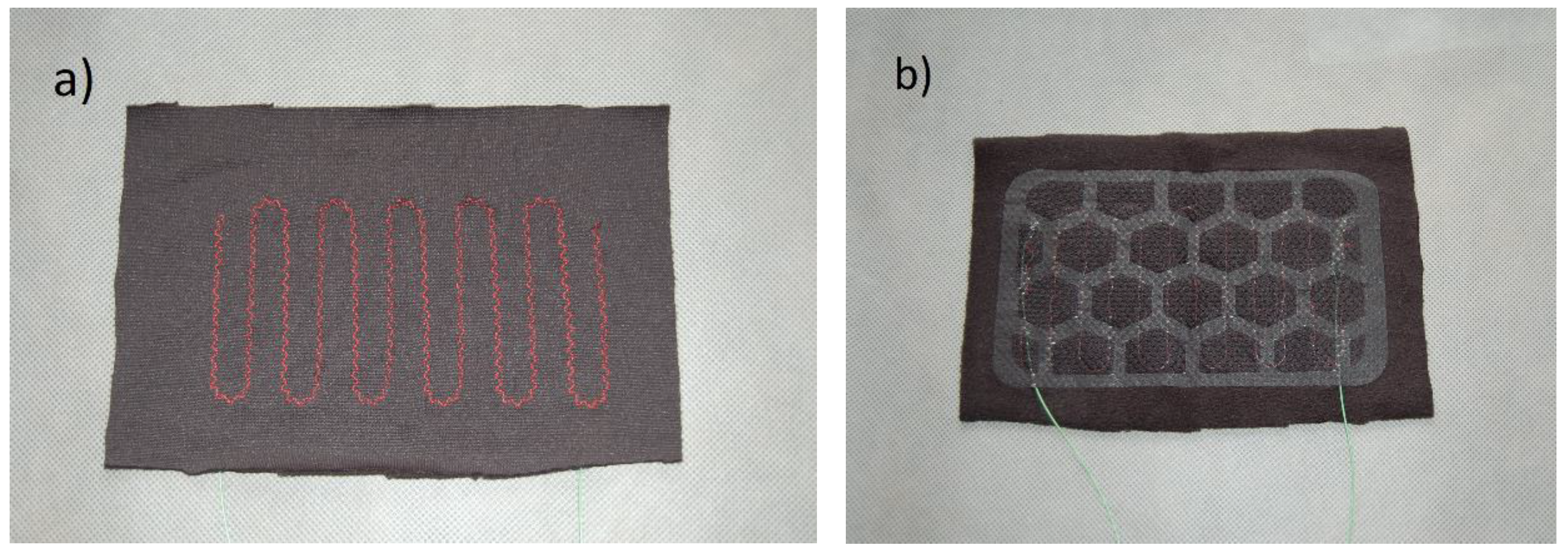
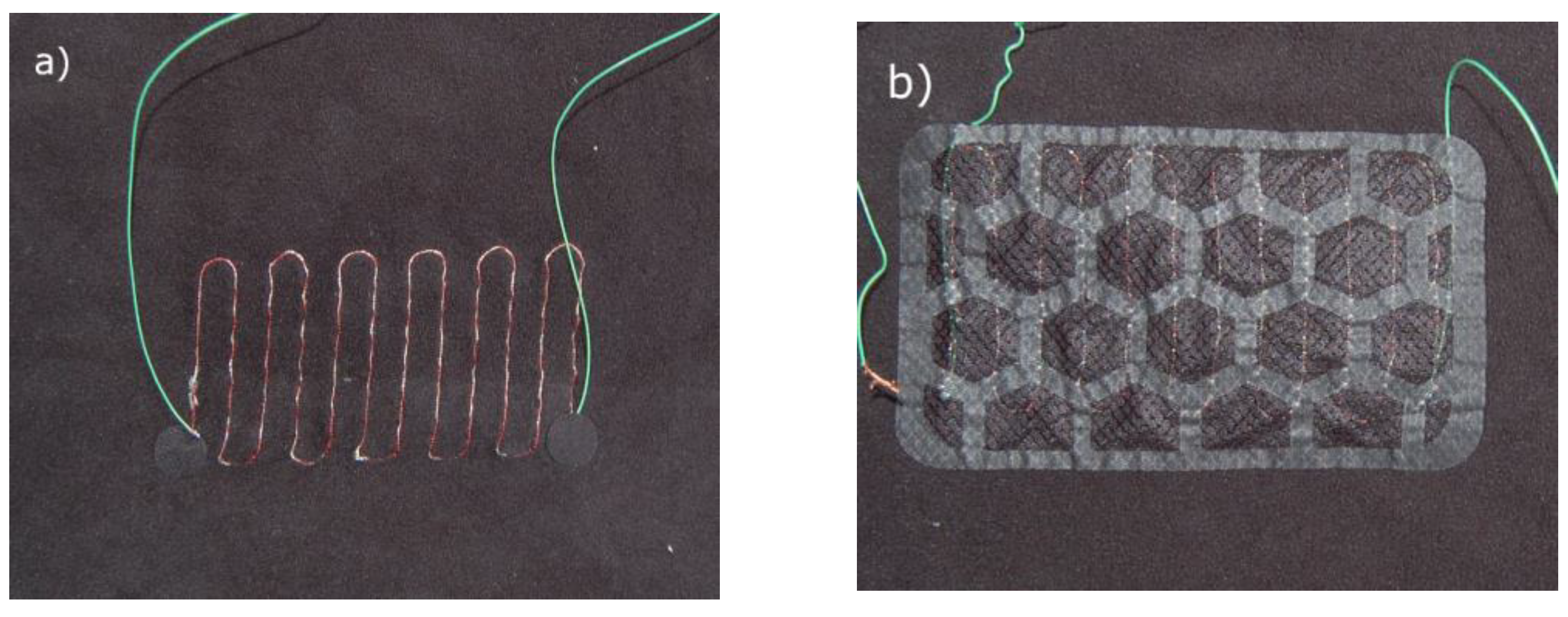
Two variants of heating inserts were produced. One variant was made by sewing a heating thread onto the knitted fleece fabric by the quilting method using the CNC Template RPAS (the insert marked with the symbol A, Figure 1). The heating thread (silver) was a needle thread, and the polyester thread (red) was used as a hook thread. In the second variant, the heating thread was sewn on in the same way, but, in addition, the heating thread was secured with an openwork knitted fabric (the insert marked with the symbol B, Figure 2). The knitted fleece fabric (B1) with a sewn-in heating thread was glued together with the openwork knitted fabric using a polyurethane adhesive for fabrics (sold in sheets). This also prevented a short circuit between two opposite sections of the heating thread. The developed heating inserts were characterized by high flexibility (Figure 3).
In order to characterize the heating inserts, their basic parameters, such as thickness, weight, and surface area, were determined. The characteristics of the heating inserts are presented in Table 2.
The produced heating inserts are a compromise between size limitations and heat flux felt in a comfortable way by the user. The heating effects depend on the total power of the clothing and, therefore, on the power of a single insert, with a specific resistance at a given supply voltage applied. Real-life tests involving end users allowed the authors to determine the maximum required power to be provided by the clothing at a level of approx. 4 W per insert at a supply voltage of 5.5 V, which is safe and does not cause unpleasant tingling.
The inserts could not be too large due to the fact that steel thread limits the flexibility of clothing, which is unacceptable in professional garments intended for mountain rescuers. On the other hand, a small size of heating insert results in a high temperature increase, which may be uncomfortable or even dangerous for the user. Hence, an insert area of 165 cm2 was found as the optimal size (for the heating thread resistance of 30 Ω/m and the supply voltage of 5.5 V).

2.2. Test Methods

2.2.1. Thermal Resistance of the System of Materials with a Heating Insert and Electrical Parameters of the Heating Insert

Thermal resistance tests were carried out using a “skin model” station (ATT Władysław Tarnowski, Lodz, Poland) for material systems with heating inserts A and B. The configuration of the material system was selected depending on the test type (see Section 2.2.2, Section 2.2.3 and Section 2.2.4). The tests were performed with the heating insert turned off and on.
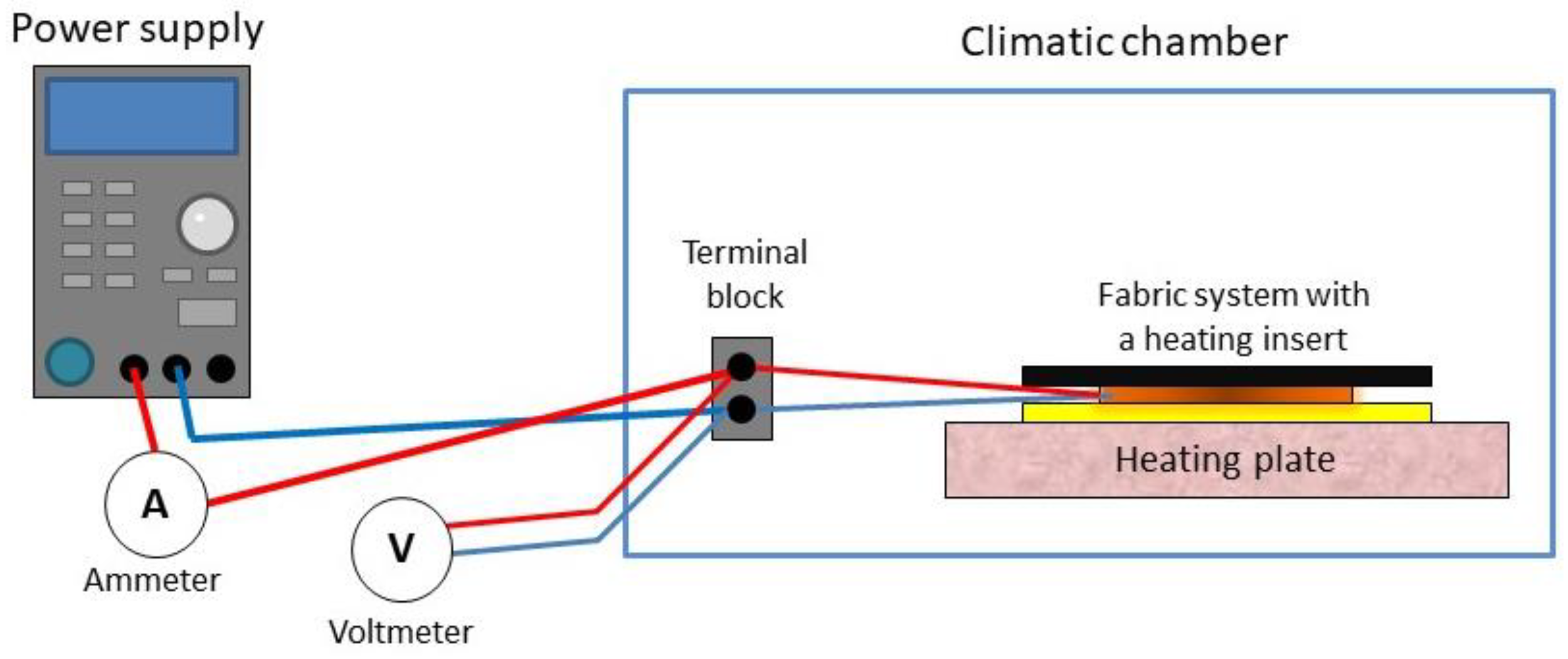
The main element of the test stand was an electrically heated 200 mm × 200 mm plate with temperature control placed in a WEISS WK11 340 climate test chamber (Weiss Umwelttechnik GmbH, Leipzig, Germany). Tests were carried out according to the method described in the standard EN ISO 11092:2014 [29], with the exception that the temperature in the climatic chamber was maintained at 5 °C or −30 °C instead of 20 °C, and the air flow rate was set to 1 m/s. The reason for the differences in the chamber temperature was to reproduce the conditions of use of protective clothing with a heating system during rescue operations in the mountains in autumn and winter. The station was equipped with an additional system for measuring the voltage and current in the heating insert (Figure 4). The system included a Korad KA3005D laboratory power supply and two Amprobe 33XR-A multimeters set to measure direct voltage (voltmeter) or direct current (ammeter).
Before determining the thermal resistance of the material system, it was necessary to determine the thermal resistance of the “bare plate” of the skin model. For this purpose, the temperature of the plate was set to 35 °C, the air temperature to 5 °C or −30 °C, and the air flow rate to 1 m/s. After reaching equilibrium conditions, the thermal resistance of the “bare plate” Rct0 was calculated in m2·K/W using the following formula:
R c t 0 = A · ( T m T a ) H H c
where A is the surface area of the measuring plate (m2); Tm is the temperature of the measuring plate (°C); Ta is the air temperature in the climatic chamber (°C); H is the heating power supplied to the measuring plate (W); and ΔHc is the correction factor of the heating power (W).
Then, the material system with a heating insert was placed on the measuring plate and an analogous measurement was made. The thermal resistance of sample Rct was calculated in m2·K/W using the formula:
R c t = A · ( T m T a ) H H c R c t 0
where Rct0 is the thermal resistance of the plate alone (m2·K/W).
It was assumed that the heating inserts will be assessed on the basis of the power and electrical resistance of the inserts and current intensity measurements, as well as the thermal resistance of the material systems with a heating insert (in the on and off state).
The electrical power of the heating insert was determined using Joule’s law, and the electrical resistance of the insert was determined using Ohm’s law.

2.2.2. Durability after Repeated Bending and Twisting

Durability tests of heating inserts A and B to repeated bending and twisting were performed. The test consisted of subjecting the heating inserts to 9000 cycles of bending and twisting at a negative temperature of −20 °C, followed by examination of change in the thermal resistance of the system of fabrics containing the heating insert (Table 3). After the bending and twisting process, the tested inserts were also visually evaluated for possible damage.
To simulate bending and twisting cycles, SJ 200 002NFEF2 82B devices (Neovision, Lodz, Poland) for testing resistances to damage by bending/twisting and a chamber for testing at negative temperatures were used. The process was carried out in accordance with the standard EN ISO 7854: (method C) [30].
After a certain number of bending and twisting cycles (2000, 5000, 9000), the tested heating inserts were evaluated organoleptically. The surface of the inserts was analyzed, and the condition and continuity of the stainless-steel heating thread and the durability of its connection to electrical wires with copper sleeves were assessed.
Thermal resistance tests were conducted with the heating inserts switched off and on. The voltage of the inserts was set to 4 V. After switching on the heating inserts, approx. 0.5 h was allowed for stabilizing the temperature of the heating thread.

2.2.3. Durability against Multiple Washing

A test of resistance of the heating inserts to the cleaning process was carried out by subjecting them to water washing under the conditions specified by the manufacturer and testing the change in the thermal resistance of the fabric systems containing the heating inserts. In this way, the durability of the inserts after a simulated maintenance process was assessed.
The washing cycles were carried out using a laboratory washing machine (Vascator FOM 71 MP, Electrolux, Stockholm, Sweden) with a 65 L horizontal drum. The process temperature was set to 30 °C, as recommended by the manufacturer of the heating inserts. The hypoallergenic washing liquid “Biały Jeleń” (Ostrzeszowskie Zakłady Chemii Gospodarczej POLLENA, Ostrzeszów, Poland) was used as a washing agent. The washing process was carried out in accordance with the standard EN ISO 6330:2012 [31]. The cleaning procedure consisted of a 15 min washing cycle, an 8 min rinsing cycle in two separate steps, and a 5 min spinning cycle.
After each cleaning cycle, the heating inserts were dried in a tumble dryer (Accudry Model 417, James H. Heal & Co. Ltd., Halifax, UK). The drying temperature was approx. 30 °C. The heating inserts were subjected to 25 water washing cycles.
After each cleaning cycle, the tested heating inserts were evaluated organoleptically. The surface of the heating inserts was analyzed, and the condition and continuity of the stainless-steel heating thread and the durability of its connection to the electrical wires with copper sleeves were assessed.
After every five cleaning cycles, the power and electrical resistance of the heating inserts were determined to characterize the electrical behavior of the inserts after multiple washings. The readings were carried out at the voltage of the insert set to 4 V. The heating inserts were placed in a system with underwear fabric and tested for thermal resistance, which is a key parameter characterizing the heat-insulating properties of materials for cold protective clothing.

2.2.4. Durability against Artificial Sweat

Testing the resistance of heating inserts to artificial sweat involved assessing the performance of the inserts after direct contact with a sweat solution and determining changes in the thermal resistance of the system of fabrics containing the heating insert. A solution of acidic artificial sweat was prepared for testing in accordance with the recommendations given in the standard EN ISO 105-E04:2013-06 “Textiles—Tests for colour fastness—Part E04: Colour fastness to perspiration” [32]. The composition of the sweat is specified in Table 4.
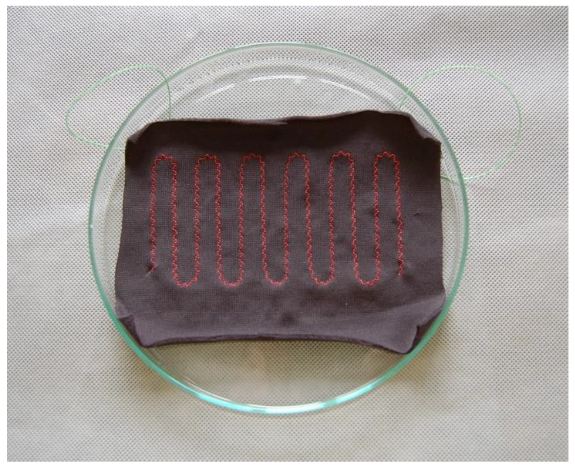
A certain amount of the prepared sweat solution was measured using a graduated beaker. Then, small doses of the sweat solution (30 mL) were pipetted onto the surface of the heating insert, which was placed in a glass pan. Artificial sweat was applied onto the insert side with visible sewing thread forming interlaces with the conductive thread. The application was started from one side of the insert, gradually moving to the other side (Figure 5). After the application was completed, measurements of the voltage and current flowing through the insert were conducted (after 5 min and after 24 h). The results were read at a voltage set to 4 V.
The heating insert was assessed in terms of electrical properties by determining power and electrical resistance. In addition, the heating insert together with the underwear material was subjected to a thermal resistance test to check the effects of sweat exposure on heat-insulating properties.

2.2.5. Temperature between the Layers of the Material System with a Heating Insert

Studies of temperature distribution between the layers of the system of materials with a heating insert were aimed to assess the inserts in terms of the safety of their use to make sure that they would not cause burns to the wearer’s skin. Based on the results of this study, the heating efficiency of the inserts and the ability of the fabric system to retain the heat generated by the insert next to the skin were also evaluated.
The tests conducted for the material system containing heating insert B (with an openwork knitted fabric) are characterized in Table 5.
The study used a “skin model” test stand equipped with a measuring system for determining the voltage and current of the heating insert (as in Section 2.2.1) and with miniature thermocouples from CZAKI, having an accuracy of ±0.1 °C. The system with a heating insert was tested at −30 °C, with a wind speed of 1 m/s, using different voltages supplied to the insert, i.e., 0 V, 1.1 V, 2.2 V, 3.3 V, 4.4, V, and 5.5 V, which corresponded to the electrical power of the insert of 0 W, 0.16 W, 0.63 W, 1.40 W, 2.51 W, and 3.95 W. The distribution of temperature sensors (thermocouples) in the system of materials with a heating insert is presented in Figure 6.
The material system with a heating insert was mounted on the heating plate of the “skin model”, with the thermocouples placed between the layers of materials at the location of the heating insert (T1, T2, and T3) and next to the heating insert (T1′). An appropriate DC voltage was set on the power supply, starting from the lowest value, i.e., 0 V. The temperature was read after approx. 30 min, and then the voltage was increased. Again, the temperature was read between individual layers of the system after approx. 30 min. In addition to the temperature, the power of the heating plate of the “skin model” was also recorded, on the basis of which the thermal resistance of the material system was determined.

3. Results and Discussion

3.1. Resistance to Multiple Bending and Twisting

Organoleptic examination of the heating inserts after multiple bending and twisting cycles showed no damage to the knitted fabric or heating thread. It was found that variant B of the heating inserts was more durable than variant A. This was due to the use of an additional openwork knitted fabric in variant B, acting as a layer protecting the heating thread (Figure 7 and Figure 8).
As demonstrated in the study, a simulation of actual use in the form of forced bending and twisting cycles did not change the power and electrical resistance of the heating inserts (Table 6). The power of the inserts remained at approx. 2.1 W and was very similar for inserts without (variant A) and with an openwork fabric (variant B). In the case of insert A, no changes in electrical resistance were observed after bending and twisting; this parameter remained at the level of approx. 6.9 Ω. However, in the case of insert B, bending led to a slight increase in electrical resistance of approx. 5% from 6.89 Ω for a new insert to 7.21 Ω for an insert subjected to 9000 bending and twisting cycles. However, these differences were not significant. It can, therefore, be concluded that the electrical parameters of the inserts did not deteriorate as a result of multiple bending and twisting cycles. Studies by Hamdani et al. [33], who examined knitted structures with stainless steel, have shown that heating elements made of similar stainless steel can generate a larger amount of heat at a very low voltage (1.5–3 V). Hamdani et al. [33] noted that stainless steel yarn is recommended where a high heat output is required. These researchers found that the interlock structure was a better choice for heating fabrics due to its stability and also because it was observed to reach a higher temperature as compared to that of a plain structure for the same amount of voltage supplied.
Islam et al. [34] investigated the effect of bending cycles on the electrical resistance of conductive e-textiles coated with carbon black ink, designed for heating inserts. The material was subjected to 1000 bending cycles using the developed hand-operated system, in which a sample of material was placed on a wooden base. To summarize, bending was carried out with the help of the moving part. Electrical resistance was tested with a probe at two ends of the sample after every 100 bending cycles. The tests demonstrated that the electrical resistance of the material increased by as much as 327% after 1000 bending cycles. In the case of inserts tested in the presented study, electrical resistance, practically, did not change after such a number of bending cycles, which indicates their very high durability to mechanical damage.
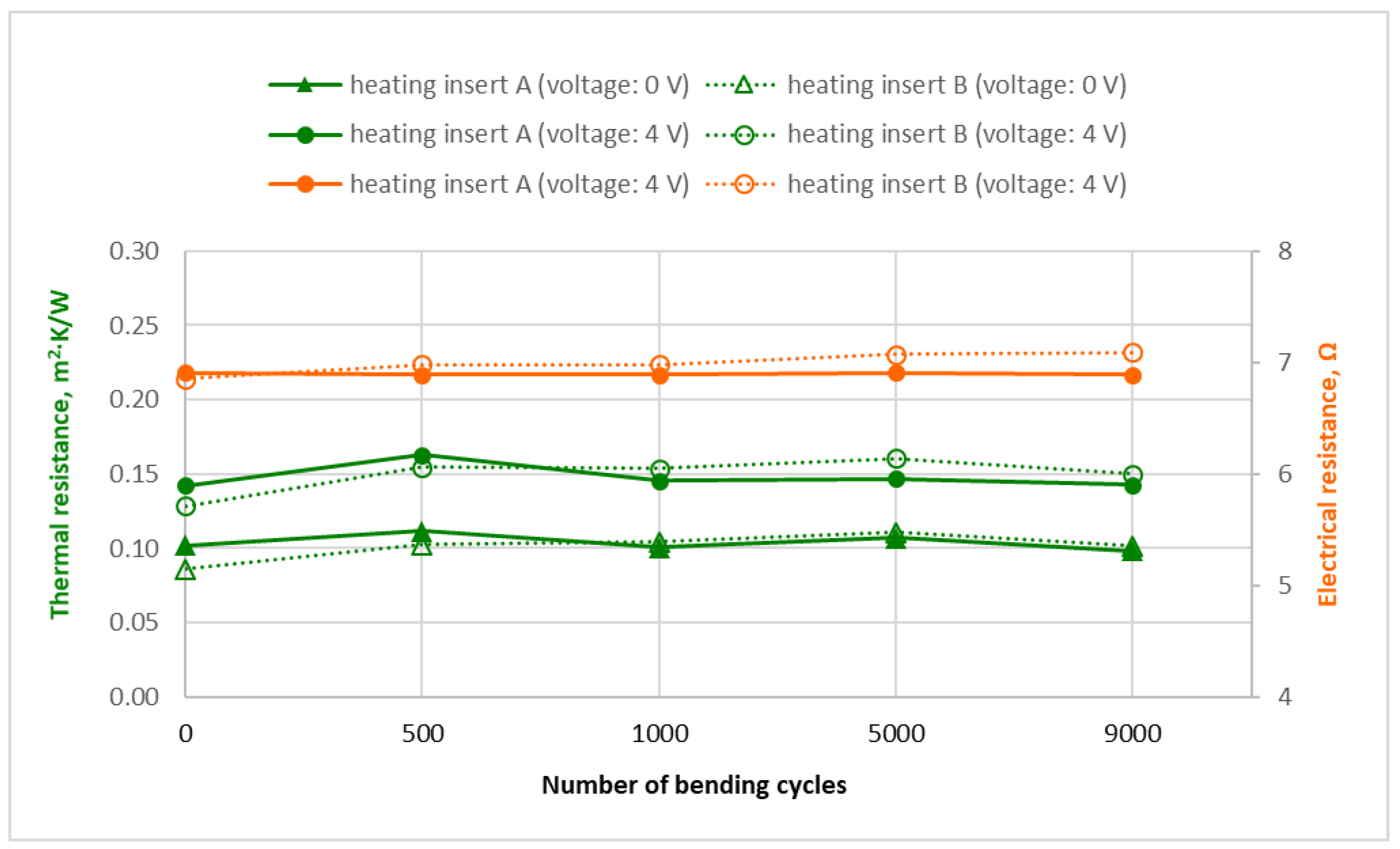
Subjecting the inserts to bending and twisting, practically, did not affect the value of thermal resistance of the fabric system with a heating insert. In the case of insert A (without an openwork fabric) in the off state, the thermal resistance of the material system remained at the level of approx. 0.10 m2K/W before and after 9000 bending/twisting cycles. After switching on the power supply set to 4 V, the thermal resistance of the system increased by approx. 40% to 0.14 m2K/W. This value remained unchanged even after 9000 bending/twisting cycles, which indicates a high resistance of the heating insert A to multiple bending and twisting cycles (Figure 9).
In the case of insert B (with an openwork fabric), slight fluctuations in thermal resistance after bending and twisting might result from bends created in the heating insert, which, in turn, may have led to the occurrence of small air voids between the layers of the material system (air is a very good heat insulator). However, fluctuations in thermal resistance were small, of the order of max. 0.016 m2K/W. The use of an openwork knitted fabric in insert B did not increase its thermal resistance. This parameter was at a similar level as in the case of insert A (without an openwork knitted fabric) both in the off and on states.

3.2. Resistance to Multiple Washing Cycles

The tests have demonstrated that subjecting the insert to multiple cycles of water washing at a low temperature (30 °C) did not cause a significant change in electrical power and resistance (Table 7). After 25 washing cycles, the power of the insert decreased slightly by 0.13 W. In contrast, its electrical resistance increased from 6.86 Ω for a new insert to 7.21 Ω for an insert after 25 washing cycles. The above differences are not significant. The developed heating inserts were found to retain their electrical properties after repeated washing cycles.
As in the case of determining resistance to multiple bending and twisting cycles, organoleptic observations of heating inserts after multiple washing cycles did not show any damage to the knitted fabric or heating thread (Figure 10).
Research concerning the washability of e-textiles and heating elements has been very limited. As indicated by Rotzler et al. [35], the current standards in the field of textiles lack an adequate consideration of integrated electrically conductive and electronic components of e-textiles. There is a need to develop a future standard to provide a range of washing programs for materials incorporating different kinds of electrical devices. Gaubert et al. [36] found in their research that the resulting damage was quite limited if the tested conductive textiles were only exposed to a single cleaning factor (a detergent or mechanical agitation). Significant losses in conductivity did not occur until multiple factors acted and interacted at the same time. Therefore, it is very important to develop a correct estimation of washability under real usage conditions for materials with conductive elements.
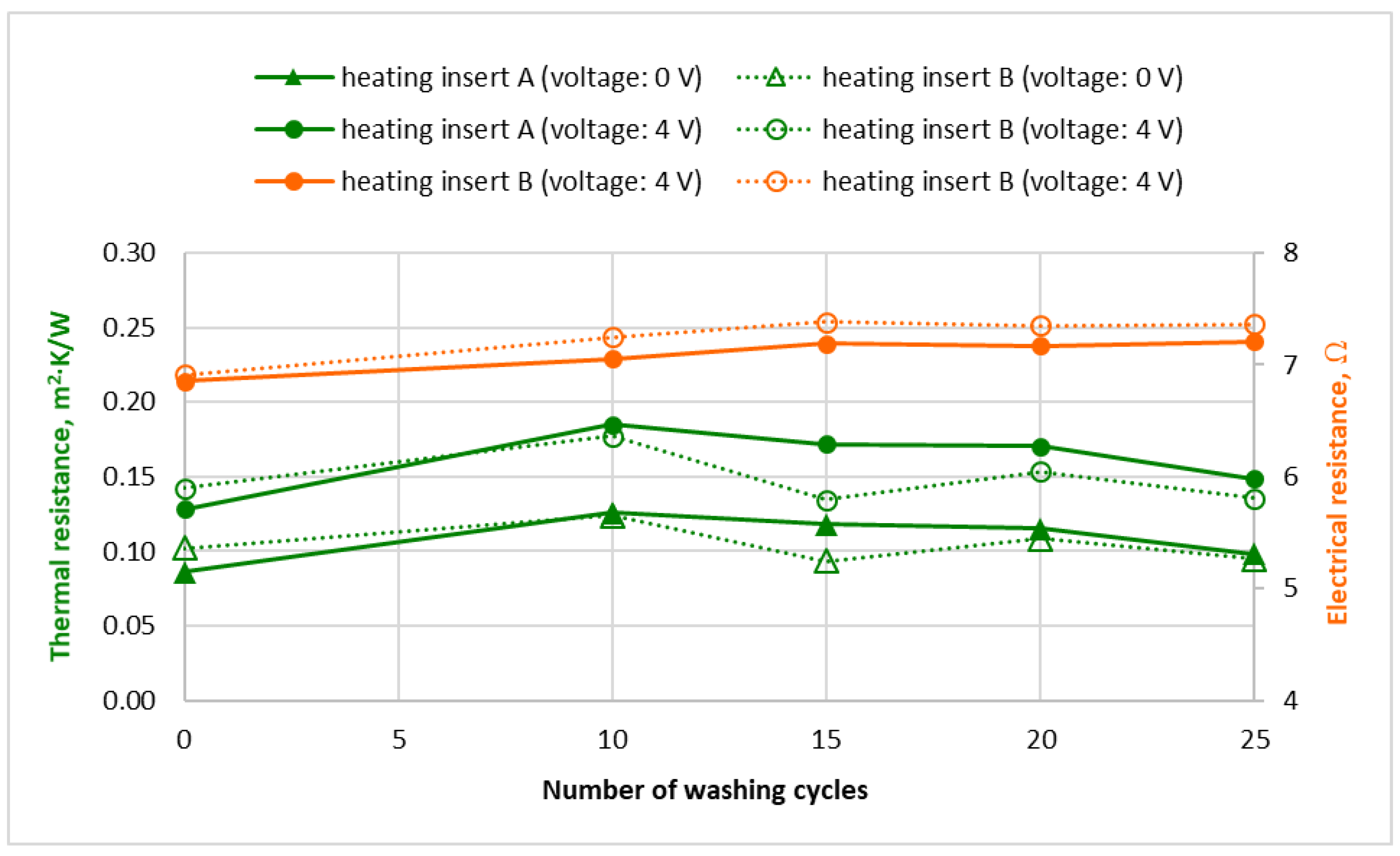
Studies of the thermal resistance of heating inserts in a system with underwear showed that the repeated washing of the inserts did not cause a significant change in their thermal resistance. In both insert variants—without an openwork knitted fabric (A) and with such a fabric protecting the conductive thread (B)—thermal resistance was at a similar level before the first washing (0 cycles) and after 25 washing cycles. The difference amounted to approx. 0.15 m2K/W (Figure 11), which attests to the durability of the inserts and their resistance to the water washing process.
It was found that the thermal resistance of both insert variants that were turned off during the test was lower by approx. 0.05 m2K/W as compared to the inserts that were turned on in the heating operating mode (Figure 11).
In the case of heating insert A, it was noticed that washing resulted in the heating thread being locally pulled up to form loops. Therefore, it was decided to discontinue further research into that insert. The washing process showed that the heating thread must be secured with an additional material against mechanical damage, as is the case with insert B.

3.3. Resistance to Sweat Exposure

It was observed that one-time wetting of the heating insert (variant B) with artificial sweat during its operation did not cause disturbances in its functioning. There were no significant differences in either the power or electrical resistance of the insert before wetting (in new state), after wetting with artificial sweat, or after drying the insert. The electrical power of a new heating insert before exposure to artificial sweat (1.95 W) was comparable to the power of the insert after its wetting and drying (1.89 W) (Table 8). Electrical resistance was also at similar levels: 6.92 Ω for a new insert vs. 6.98 for an insert moistened with artificial sweat and dried. It was found that the heating insert was not damaged after wetting with acidic artificial sweat, and its operation was not disturbed. Similar research was conducted by Hirman et al. [37], who analyzed the influence of sweat on the reliability of joints and sensors in e-textiles. In their experiments, these researchers used the same type of acidic sweat, prepared according to the international standard ISO105-E0, to investigate the accelerated aging of joints in soldered samples. In contrast, the methodology of experimental aging with sweat was different. Hirman et al. [37] soaked the samples in a sweat solution for half an hour every day over twenty-four days. Similarly, they noted that the electrical resistance of joints in soldered samples during sweat-induced aging was low and stable for both sweat types without significant differences between sample types. The results for adhesive-bonded samples showed that electrical resistance grows during sweat-induced aging. However, after an initial increase, the values remained relatively stable.

3.4. Temperature Test Results

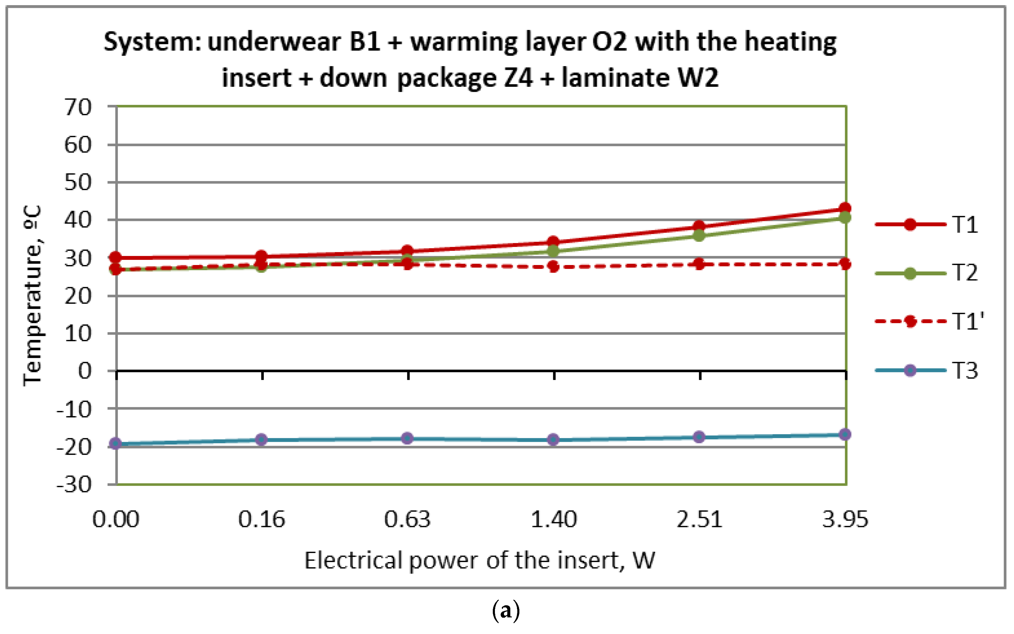
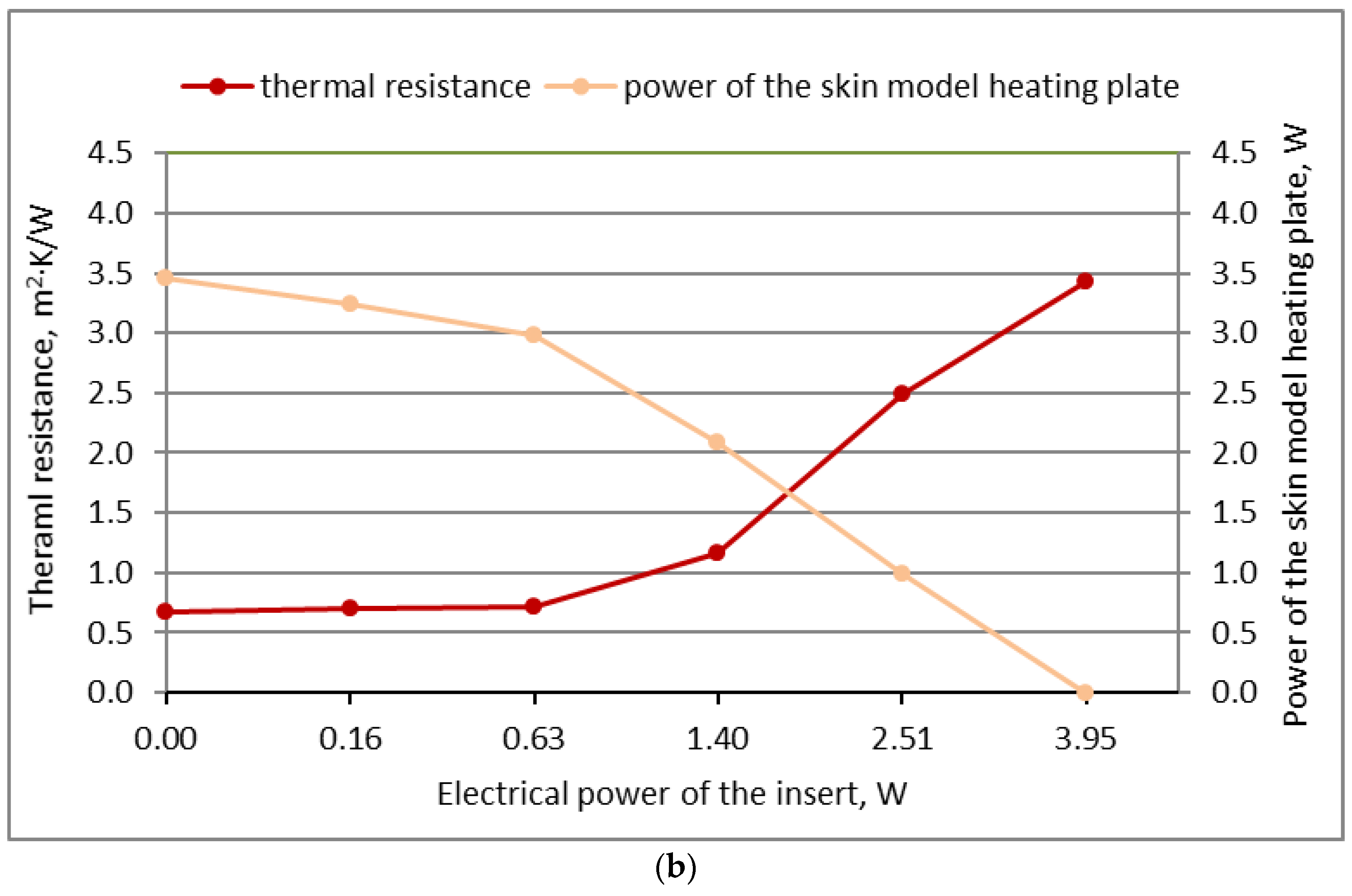
The results of temperature distribution between the layers of the fabric system with heating insert B (Figure 12a) demonstrated that temperature T1 (between underwear U1 and material O2 with the insert—at the site of its placement) and T2 (between material O2 with the insert and down package Z4) rose gradually with increasing electrical power of the insert, with a significant increment noted only after exceeding the power of 0.63 W. As it can be seen from the graph (Figure 12a), temperature T1 at the highest power of 3.94 W did not exceed 43 °C, which is in accordance with the requirements of the standard PN-EN 60335-2-17 (max. temp. 50 °C) [38]. Therefore, it can be deemed that the applied heating insert will not cause burns to the user’s skin. When using the maximum power of the insert, the measuring plate of the “skin model” was turned off (the power of the plate was 0 W). The thermal resistance of the system then increased to 3.5 m2·K/W (Figure 12b).
Temperature T1′ (between underwear U1 and material O2 with the insert—next to the insert), regardless of the insert power, was at the level of approx. 30 °C, which indicates that the heat generated by the insert was mainly concentrated in the area of the insert, while the side areas of the garment were underheated. Analyzing the temperatures recorded by thermocouple T2, it can be seen that they were slightly lower than T1 at all powers of the heating insert, which indicates that most of the heat was retained at the “skin.” This is also evidenced by the very small changes of temperature T3 (between down package Z4 and laminate W2) at the max. level of 2.4 °C, with increased heating insert power.
Studies conducted by Stygiene et al. [39] have also demonstrated that the heating efficiency of a heating insert depends on the combination of the layers of the clothing worn. Research on volunteers showed that the use of a t-shirt with a heating insert on the inside powered with 5 V resulted in an increase in skin temperature to 38.8 °C. However, in the case where an additional sweater was worn, skin temperature increased to 39.3 °C. At a lower voltage of the insert, i.e., 3 V, skin temperature did not exceed 36.5 °C when wearing a two-layer clothing set (t-shirt + sweater).
Tests of the temperature of the external surface of the heating insert using a thermal imaging camera made it possible to assess heat loss to the environment. Depending on the supply voltage level, the surface temperature of the insert was in the range of 27.74–36.38 °C. It was suggested that these losses could be reduced by increasing the thermal insulation properties of the outer layer of the heating insert or by using layered clothing. Our research has confirmed the latter hypothesis because, as mentioned previously, the temperature above the heating insert was lower than that between the underwear and the insert. At the highest voltage, i.e., 5.5 V (corresponding to a power of 3.95 W), the temperature on the surface of the insert was approx. 40 °C and approx. 4 °C higher than the surface temperature of the insert developed by Stygiene et al. [39].

4. Conclusions

The study presents the developed heating inserts incorporating textile materials and a conductive thread. The results indicate that the inserts are characterized by high durability in conditions simulating real use. The exposure of the inserts to multiple low-temperature water washings (25 cycles), as well as to multiple bending cycles (9000 cycles) and artificial sweat, did not cause a significant change to the electrical power and resistance of the inserts. The operation of the inserts after exposure to these factors remained normal. Organoleptic observations of the heating inserts after multiple washing or bending and twisting cycles showed no damage to the knitted fabric or heating thread. However, heating insert A turned out to be insufficiently resistant to washing, as, during this process, the heating thread was locally pulled up to form loops. Hence, the conclusion is that the heating element must be secured with an additional material against mechanical damage, as in the case of insert B. The conducted research revealed the need to use an additional layer protecting the heating thread in the construction of the heating insert.
Tests of protective properties, determining the level of protection against cold, demonstrated that the thermal resistance of the developed heating inserts (type B) in a system with underwear fabric does not change significantly after repeated washing. The process of the multiple bending and twisting of the inserts (9000 cycles) also did not reduce the thermal resistance of the system of materials with the heating insert. Maintaining thermal resistance at a comparable level after the impact of mechanical factors will contribute to easier modeling of the insert’s thermal properties. The above proves a high resistance of the heating thread in wear and tear tests (washing, bending) and the high quality of the inserts. The temperature between the knitted underwear fabric and the warming material incorporating the selected heating insert with an openwork knitted fabric—at the site of insert placement at its highest power, i.e., 3.94 W—did not exceed 43 °C, which meets the requirements of PN-EN 60335-2-17 (max. temp. 50° C). It can, therefore, be concluded that the heating insert used should not cause burns to the user’s skin. Taking this into account, the developed heating inserts as safe for use in contact with humans and can be incorporated in clothing.
The wetting of heating insert B with artificial sweat during its operation did not damage it or interfere with its functioning. The electrical power of the new heating inserts was comparable to the power of the inserts that were wetted with artificial sweat and dried. The conducted research resulted in a positive evaluation of the developed inserts and confirmed their applicability according to the intended use. It was concluded that the materials used, and, in particular, the heating thread, were sufficiently resistant to artificial sweat, simulating the harmful effects of human sweat (due to the various types of salts contained in the sweat, the connections of the inserts may have been damaged).

Author Contributions

Conceptualization, S.K. and A.G.; methodology, S.K. and A.G.; investigation, S.K., A.G., R.K. and B.P.; writing—original draft preparation, S.K., A.G., B.M. and P.M.; writing—review and editing, S.K., A.D., R.K. and B.P.; visualization, A.G. and S.K.; supervision, G.B.; project administration, G.B. All authors have read and agreed to the published version of the manuscript.

Funding

This work was supported by the Project “Personalized Protective Thermally Active Clothing” from The National Centre for Research and Development, Poland under Grant POIR.04.01.04-00-0070/18.

Institutional Review Board Statement

Not applicable.

Informed Consent Statement

Not applicable.

Data Availability Statement

Data available on request due to restrictions eg. privacy or ethical. The data presented in this study are available on request from the corresponding author.

Conflicts of Interest

The authors declare no conflict of interest. The funders had no role in the design of the study; in the collection, analyses, or interpretation of data; in the writing of the manuscript, or in the decision to publish the results.

References

  1. Mäkinen, H.; Jussila, K. Cold-protective clothing: Types, design and standards, protective clothing managing thermal stress. In Protective Clothing, 1st ed.; Wang, F., Gao, C., Eds.; Woodhead Publishing (An Important of Elsevier): Sawston, UK, 2014; pp. 3–38. [Google Scholar]
  2. Wang, L.; Xu, D.-H.; Cheng, J.-X.; Zhou, X.-H. A Model of Heat and Moisture Transfer through Parallel Pore Textiles. J. Fiber Bioeng. Inform. 2011, 3, 250–255. [Google Scholar] [CrossRef]
  3. Sampatth, M.; Aruputharaj, A.; Senthilkumar, M.; Nalankilli, G. Analysis of thermal comfort characteristics of Moisture management finished knitted fabrics from different yerns. J. Ind. Text. 2012, 42, 19–22. [Google Scholar] [CrossRef]
  4. Shah, M.A.; Pirzada, B.M.; Price, G.; Shibiru, A.L.; Qurashi, A. Applications of nanotechnology in smart textile industry: A critical review. J. Adv. Res. 2022, 38, 55–75. [Google Scholar] [CrossRef] [PubMed]
  5. Bahadir, S.K.; Sahin, U.K. A wearable heating system with a controllable e-textile-based thermal panel. In Wearable Technologies; Ortiz, J.H., Ed.; InTech. Publishing: London, UK, 2018. [Google Scholar]
  6. Ueng, T.; Cheng, K. Friction core-spun yarns for electrical properties of woven fabrics. Compos. Part A Appl. Sci. Manuf. 2001, 32, 1491–1496. [Google Scholar] [CrossRef]
  7. Fang, S.; Wang, R.; Ni, H.; Liu, H.; Liu, L. A review of flexible electric heating element and electric heating garments. J. Ind. Text. 2022, 51, 101S–136S. [Google Scholar] [CrossRef]
  8. Wang, F.; Gao, C.; Kuklane, K.; Holmér, I. A Review of Technology of Personal Heating Garments. Int. J. Occup. Saf. Ergon. 2010, 16, 387–404. [Google Scholar] [CrossRef] [Green Version]
  9. Jussila, K.; Sormunen, E.; Remes, J. Case study: Perceived usability of emergency communication equipment with and without protective gloves in the cold. J. Search Rescue 2013, 1, 1–15. [Google Scholar]
  10. Jussila, K.; Valkama, A.; Remes, J.; Anttonen, H.; Peitso, A. The Effect of Cold Protective Clothing on Comfort and Perception of Performance. Int. J. Occup. Saf. Ergon. 2010, 16, 185–197. [Google Scholar] [CrossRef] [Green Version]
  11. Wang, F.; Lee, H. Evaluation of an Electrically Heated Vest (EHV) Using a Thermal Manikin in Cold Environments. Ann. Occup. Hyg. 2010, 54, 117–124. [Google Scholar] [CrossRef] [Green Version]
  12. Kempson, G.E.; Clark, R.P.; Goff, M.R. The design, development and assessment of electrically heated gloves used for protecting cold extremities. Ergonomics 1988, 31, 1083–1091. [Google Scholar] [CrossRef]
  13. Chiu, C.-C.; Shyr, T.-W.; Chu, H.-C.; Chung, Y.-C.; Lan, C.-Y. A wearable e-health system with multi-functional physiological measurement. In Proceedings of the World Congress on Medical Physics and Biomedical Engineering, Berlin, Germany, 27 August–1 September 2006. [Google Scholar]
  14. Repon, M.R.; Mikučionienė, D. Progress in flexible electronic textile for heating application: A critical review. Materials 2021, 14, 6540. [Google Scholar] [CrossRef] [PubMed]
  15. Holmér, I.; Gao, C.; Wang, F. Adaptive strategies to preserve comfort in cold rooms-is personal warming an alternative. In Proceedings of the 6th International Conference on Cold Climate-Heating, Ventilating and Air-Conditioning (Cold Climate HVAC 2009), Sisimiut, Greenland, 16–19 March 2009. [Google Scholar]
  16. Rantanen, J.; Impio¨, J.; Karinsalo, T.; Malmivaara, M.; Reho, A.; Tasanen, M.; Vanhala, J. Smart Clothing Prototype for the Arctic Environment. Pers. Ubiquitous Comput. 2002, 6, 3–16. [Google Scholar] [CrossRef]
  17. Bahadir, S.K.; Jevsnik, S.; Fakin, D.; Sahin, U.K. Color and electrical resistance evaluation of cotton fabrics composed of stainless steel yarns treated with direct and reactive dyes. Text. Res. J. 2016, 86, 1356–1371. [Google Scholar] [CrossRef]
  18. Tabaczyńska, A.; Dąbrowska, A.; Słoma, M. Printed Graphene, Nanotubes and Silver Electrodes Comparison for Textile and Structural Electronics Applications. Sensors 2021, 21, 4038. [Google Scholar] [CrossRef] [PubMed]
  19. Li, Z.; Li, H.; Zhu, X.; Peng, Z.; Zhang, G.; Yang, J.; Wang, F.; Zhang, Y.; Sun, L.; Wang, R.; et al. Directly Printed Embedded Metal Mesh for Flexible Transparent Electrode via Liquid Substrate Electric-Field-Driven Jet. Adv. Sci. 2022, 9, 2105331. [Google Scholar] [CrossRef]
  20. Zhu, X.; Liu, M.; Qi, X.; Li, H.; Zhang, Y.-F.; Li, Z.; Peng, Z.; Yang, J.; Qian, L.; Xu, Q.; et al. Templateless, Plating-Free Fabrication of Flexible Transparent Electrodes with Embedded Silver Mesh by Electric-Field-Driven Microscale 3D Printing and Hybrid Hot Embossing. Adv. Sci. 2021, 33, 2007772. [Google Scholar] [CrossRef]
  21. Li, H.; Li, Z.; Li, N.; Zhu, X.; Zhang, Y.; Sun, L.; Wang, R.; Zhang, J.; Yang, Z.; Yi, H.; et al. 3D Printed High Performance Silver Mesh for Transparent Glass Heaters through Liquid Sacrificial Substrate Electric-Field-Driven Jet. Small 2022, 18, 2107811. [Google Scholar] [CrossRef] [PubMed]
  22. Zhu, X.; Xu, Q.; Li, H.; Liu, M.; Li, Z.; Yang, K.; Zhao, J.; Qian, L.; Peng, Z.; Zhang, G.; et al. Fabrication of High-Performance Silver Mesh for Transparent Glass Heaters via Electric-Field-Driven Microscale 3D Printing and UV-Assisted Microtransfer. Adv. Mater. 2019, 31, 1902479. [Google Scholar] [CrossRef] [PubMed]
  23. Greszta, A.; Bartkowiak, G.; Dąbrowska, A.; Gliścińska, E.; Machnowski, W.; Kozikowski, P. Multilayer Nonwoven Inserts with Aerogel/PCMs for the Improvement of Thermophysiological Comfort in Protective Clothing against the Cold. Materials 2022, 15, 2307. [Google Scholar] [CrossRef]
  24. Tylman, W.; Kotas, R.; Kamiński, M.; Woźniak, S.; Dąbrowska, A. A Thermal Model for Processing Data from Undergarment Sensors in Automatic Control of Actively Heated Clothing. Energies 2022, 15, 169. [Google Scholar] [CrossRef]
  25. Pękosławski, B.; Marciniak, P.; Starzak, Ł; Stawiński, A.; Bartkowiak, G. Power Supply and Control Unit for Actively Heated Protective Clothing with Photovoltaic Energy Harvesting. Energies 2022, 15, 5656. [Google Scholar] [CrossRef]
  26. Tylman, W.; Kotas, R.; Kamiński, M.; Dąbrowska, A.; Młynarczyk, M. Modeling and Experimental Verification of the Required Power for Electrically Heated Clothing. Energies 2022, 15, 7713. [Google Scholar] [CrossRef]
  27. EN ISO 5084:1996; Textiles—Determination of Thickness of Textiles and Textile Products. European Committee for Standarization: Brussels, Belgium, 1996.
  28. EN 12127:1997; Textile Fabrics—Determination of Mass Per Unit Area Using Small Samples. European Committee for Standarization: Brussels, Belgium, 1997.
  29. EN ISO 11092:2014; Textiles—Physiological Effects—Measurement of Thermal and Water-Vapour Resistance under Steady-State Conditions (Sweating Guarded-Hotplate Test). European Committee for Standarization: Brussels, Belgium, 2014.
  30. EN ISO 7854:1997; Rubber or Plastics-Coated Fabrics—Determination of Resistance to Damage by Flexing. European Committee for Standarization: Brussels, Belgium, 1997.
  31. EN ISO 6330:2012; Washing and Drying Procedures for Textile Testing. European Committee for Standarization: Brussels, Belgium, 2012.
  32. EN ISO 105-E04:2013-06; Textiles—Tests for Colour Fastness—Part E04: Colour Fastness to Perspiration. European Committee for Standarization: Brussels, Belgium, 2013.
  33. Hamdani, S.T.A.; Fernando, A.; Maqsood, M. Thermo-mechanical behavior of stainless steel knitted structures. Heat Mass Transf. 2016, 52, 1861–1870. [Google Scholar] [CrossRef]
  34. Islam, R.; Khair, N.; Ahmed, D.M.; Shahariar, H. Fabrication of low cost and scalable carbon-based conductive ink for E-textile applications. Mater. Today Commun. 2019, 19, 32–38. [Google Scholar] [CrossRef]
  35. Rotzler, S.; von Krshiwoblozki, M.; Schneider-Ramelow, M. Washability of e-textiles: Current testing practices and the need for standardization. Text. Res. J. 2021, 91, 2401–2417. [Google Scholar] [CrossRef]
  36. Gaubert, V.; Gidik, H.; Bodart, N.; Koncar, V. Investigating the Impact of Washing Cycles on Silver-Plated Textile Electrodes: A Complete Study. Sensors 2020, 20, 1739. [Google Scholar] [CrossRef] [Green Version]
  37. Hirman, M.; Navratil, J.; Radouchova, M.; Stulik, J.; Soukup, R. Influence of Sweat on Joint and Sensor Reliability of E-Textiles. Energies 2022, 15, 506. [Google Scholar] [CrossRef]
  38. EN 60335-2-17: 2013/A11:2019; Household and Similar Electrical Appliances—Safety—Part 2–17: Particular Requirements for Blankets, Pads, Clothing and Similar Flexible Heating Appliances. European Committee for Standarization: Brussels, Belgium, 2019.
  39. Stygienė, L.; Varnaitė-Žuravliova, S.; Abraitienė, A.; Padleckienė, I.; Krauledas, S. Investigation of textile heating element in simulated wearing conditions. Autex Res. J. 2021, 21, 207–215. [Google Scholar] [CrossRef]
Figure 1. Photographs of the heating insert (variant A)—outer surface (a) and inner surface (b).
Applsci 13 04879 g001
Figure 2. Photographs of the heating insert (variant B)—outer surface (a) and inner surface (b).
Applsci 13 04879 g002
Figure 3. Photograph of the heating insert (variant B) hanging from a shelf.
Applsci 13 04879 g003
Figure 4. Diagram of the measuring system for testing the thermal resistance of the system of materials with a heating insert.
Applsci 13 04879 g004
Figure 5. Photograph of the heating insert (variant A) exposed to artificial sweat.
Applsci 13 04879 g005
Figure 6. Arrangement of thermocouples in the fabric system with heating function for protective clothing for mountain rescuers.
Applsci 13 04879 g006
Figure 7. Photographs of the heating insert (variant A) after 9000 cycles of bending and twisting—outer surface (a) and inner surface (b).
Applsci 13 04879 g007
Figure 8. Photographs of the heating insert (variant B) after 9000 cycles of bending and twisting—outer surface (a) and inner surface (b).
Applsci 13 04879 g008
Figure 9. Thermal resistance test results for systems of materials incorporating heating inserts A and B depending on the number of bending and twisting cycles.
Applsci 13 04879 g009
Figure 10. Photographs of heating inserts after 25 cycles of washing—inner surface of variant A (a) and inner surface of variant B (b).
Applsci 13 04879 g010
Figure 11. Thermal resistance of fabric systems with a heating insert depending on the number of washing cycles.
Applsci 13 04879 g011
Figure 12. Test results for the system of materials with heating insert B (system: U1 + insert B + Z4 + W2 at −30 °C: (a) temperature changes between the layers of the system depending on the power of the heating insert, (b) a graph of the dependence of the thermal resistance of the system with the heating insert and that of the power of the “skin model” measuring plate on the power of the heating insert.
Applsci 13 04879 g012aApplsci 13 04879 g012b
Table 1. Characteristics of the textile materials used for the preparation of heating inserts.
No.SymbolFabric
Composition
Mass per
Unit Area, g/m2
Thickness,
mm
Thermal
Resistance, m2·K/W
knitted fleece fabricB1 100% PES131.3 ± 0.90.83 ± 0.010.024 ± 0.001
openwork
knitted fabric
S1100% PES71.0 ± 3.50.35 ± 0.00not tested
Table 2. Characteristics of the heating inserts.
SymbolThickness 1, mmMass 2, gArea, mm2
A 1.82 ± 0.045.216,500
B2.21 ± 0.065.816,500
1 according to EN ISO 5084:1996 [27]. 2 according to EN 12127:1997 [28].
Table 3. Variants of the tested material systems.
No.Designation of the SystemArrangement of Layers in the Material System
1U1 + insert ALayer I (underwear fabric): knitted fabric U1 (100% PES), 131 g/m2
layer II: heating insert A
2U1 + insert Blayer I (underwear fabric): knitted fabric U1 (100% PES), 131 g/m2
layer II: heating insert B
Table 4. Artificial sweat composition.
Chemical Composition (Formula)Acidic Solution
pH = 5.5 ± 0.2
Amount
L-histidine monohydrochloride monohydrate (C6H9O2N3 HCL H2O)0.5 g
Sodium chloride (NaCl)5.0 g
Disodium hydrogen orthophosphate dihydrate (NaH2PO4 2H2O)2.2 g
Total volume1000 mL
Table 5. Material systems with heating insert for temperature distribution testing.
No.Designation of the SystemArrangement of Layers in the Material System
1U1 + insert B + Z4 + W2layer I (underwear fabric): knitted fabric U1 (100% PES), 131 g/m2
layer II: heating insert B
layer II (for down jacket): down package made of Z4 fabric (100% PA, 131 g/m2) with filling: 92% goose down, 8% feathers
layer III (for outer jacket): vapor-permeable laminate W2 (fabric: 100% PES, membrane: 100% PU)
Table 6. Electrical properties of heating inserts (variant A and B) after multiple bending cycles.
Number of Bending CyclesApplied Voltage, VPower, WElectrical Resistance, Ω
Variant AVariant BVariant AVariant B
04 V2.092.156.916.86
5002.082.116.896.98
10002.082.046.896.98
50002.092.066.917.07
90002.082.076.897.09
Table 7. Electrical properties of the heating insert (variant B) after multiple washings.
Number of Washing CyclesApplied Voltage, VPower, WElectrical Resistance, Ω
04 V2.156.86
102.067.06
152.027.19
202.017.17
252.027.21
Table 8. Electrical properties of heating insert (variant B) after exposure to sweat.
VariantApplied
Voltage, V
Power, WElectrical
Resistance, Ω
New4 V1.956.92
after exposure to sweat (wet, 5 min)2.006.87
after exposure to sweat (dry, 24 h)1.896.98
Disclaimer/Publisher’s Note: The statements, opinions and data contained in all publications are solely those of the individual author(s) and contributor(s) and not of MDPI and/or the editor(s). MDPI and/or the editor(s) disclaim responsibility for any injury to people or property resulting from any ideas, methods, instructions or products referred to in the content.