Abstract
The application of a semi-flexible pavement (SFP) is an effective solution to solve the rutting problems of the autonomous rail rapid transit (ART) system. The service environment of an ART pavement is significantly different from that of the conventional pavement due to the large axle load and high tire pressure of ART vehicles. A test section was constructed in the Zhuzhou ART system and a tire–pavement coupling FE model was built to explore the distribution features of the dynamic responses as well as to optimize the material and structural design. The tire–pavement coupling model was firstly verified by the field test data and then, utilizing the validated model, the parameter study was performed to analyze the influence of the vehicle operating state and pavement conditions. The simulation results show that the transverse tensile strain at the bottom of the SFP layer is dominant for the fatigue cracking of the pavement. Properly reducing the tire pressure can effectively improve the tensile environment at the bottom of the SFP layer. The action of the braking force may cause significant longitudinal tensile strains at the surface of the SFP layer and lead to transverse cracking of the semi-flexible ART pavement. The interlayer bonding between the SFP layer and the asphalt layer has significant influence on the amplitude and distribution of tensile stress at the bottom of the SFP layer. Moreover, to optimize the tensile environment of the semi-flexible ART pavement, the thickness of the SFP layer and the asphalt concrete layer cannot differ too much under the premise of meeting the requirements of rutting resistance performance.
1. Introduction
With accelerated urbanization, the urban population and motor vehicle ownership are increasing. To meet the growing demand for public transportation, all countries in the world are actively developing urban public transportation [1]. The autonomous rail rapid transit (ART) combines the advantages of rail transit and bus rapid transit (BRT) [2]. The vehicle identifies the virtual track line marked on the road through the vehicle camera equipment and controls the vehicle to run along the virtual track through the vehicle control unit, which has the same exclusive right-of-way as the rail transit [3,4]. Compared with the traditional rail transit, the ART system vehicles do not need to reconstruct the physical track but only need to mark the virtual track line on the existing road base; its road construction cycle is short and the cost is low [5].
As the vehicles of ART always travel along the route marked by the virtual track (see Figure 1), it makes the pavement show significant damage characteristics during operation, i.e., the vehicle load is concentrated in a specific area of the asphalt pavement, resulting in the accumulation of deformation in the wheel track zone of the pavement to produce permanent deformation [6,7], which affects the roughness of the pavement, thus reducing the comfort of the ride and shortening the service life of the pavement.
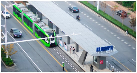
Figure 1.
The autonomous rail rapid transit in Zhuzhou, China.
Semi-flexible pavement (SFP) material is a composite material that is composited of an open-graded asphalt mixture with a high air void filled with special cement mortar [8,9,10]. It combines the viscoelasticity of asphalt concrete and the stiffness of hardened cement paste. On the one hand, SFP has better load bearing and anti-rutting performance than conventional asphalt pavement [11,12,13]. On the other hand, the riding comfort and skid resistance of the SFP surface layer are much better than the cement concrete pavement [14,15].
Compared with the dense-graded asphalt concrete that is commonly used in the conventional asphalt pavement, the SFP material has better durability and stability [15,16,17,18,19,20,21,22]. In the previous studies, SFP materials showed great potential to be used as anti-rutting overlays and surfaces in road construction [23,24,25]. It has been widely used in road intersections, bus stops, bus lanes, long steep slopes, ports, and other road sections [26,27,28]. Observation results from existing SFP roads show that the SFP layer in the asphalt road structure can effectively improve the high temperature stability of asphalt pavement. The in-site fast falling weight deflectometer (FWD) test proved that the application of the SFP layer can improve pavement resistance to dynamic load repetitions [10,14]. Numerical simulation also suggests that the application of an SFP surface layer can effectively reduce the shear stress and optimize the stress environment of pavement structure under vehicle load [29,30]. Therefore, the semi-flexible pavement material has a good application prospect in the ART system.
The previous studies on the response of pavement incorporating an SFP layer mainly focus on the general road use environment, namely passenger cars or buses. In the simulation models of previous studies, the tire–pavement contact area was regarded as a circle with a diameter of 150 mm and the contact pressure was standardized to 0.7 MPa [31]. However, the vehicle used in an ART system is different from the common passenger cars or buses, due to high capacity and special wheel set, its tire ground pressure is higher than 0.7 MPa [32]. Therefore, to simulate the unique load of ART vehicles on the pavement, it is necessary to build the tire–pavement contact model considering the practical tire conditions and pavement structure. In this way, the loading mechanism of the ART vehicle, as well as the dynamic response characteristics of the pavement that incorporates the SFP layer, could be investigated.
This study addresses the special service environment of an SFP layer in an ART system and establishes a tire–pavement coupling dynamic model based on the practical ART lines in Zhuzhou city, China. Field tests were conducted on the test sections and the collected information was utilized to calibrate the FE model. Then, using the calibrated model, the dynamic response characteristics of the ART pavement under the action of the ART vehicle load was analyzed and a series of parameter analysis was performed to reveal the influences of vehicle conditions, material properties, and structural compositions. The results may provide guidance for the optimal design of the semi-flexible ART pavement.
2. Materials and Methods
2.1. SFP and AC Materials
Semi-flexible pavement (SFP) material is a composite material formed by filling cement-based grouting material into the large void matrix asphalt mixture after rolling and molding. In this study, an SFP material and asphalt concrete (AC) with aggregate nominal maximum particle size of 13.2 mm were designed for use in the pavement of an ART system. The dynamic modulus of SFP and AC were tested utilizing the universal testing machine (UTM-25), which is produced by IPC global Co. Ltd., following the procedures specified in ASTM D3497. The test results at the frequency of 10 Hz are shown in Table 1.

Table 1.
The modulus of SFP and AC materials.
2.2. Test Section Implementation and In Situ Test
The test section was constructed based on the Zhuzhou ART line. The surface layer of the pavement structure consisted of three layers: the SFP layer, the asphalt concrete (AC) layer, and the stress absorbing layer (SAL), as shown in Figure 2. It needs to be noted that the porous asphalt mixture used for SFP-13 was the high-viscosity modified porous asphalt mixture, the styrene–butadiene–styrene (SBS) modified asphalt was used in AC-13, and crumb rubber modified asphalt and basalt aggregate with the size of 9.5~13.2 mm were used in SAL.
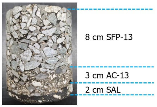
Figure 2.
The structural composition of ART pavement incorporating an SFP layer.
In order to monitor the stress–strain state of the semi-flexible ART pavement under vehicles of the ART system, sensors were buried in the test section of the pavement to continuously track and observe the mechanical response of the pavement with a sampling frequency of 5 Hz. Figure 3 shows the photos of the buried sensors on the test section site. Using the monitoring system, the stress–strain response of different layers of the ART pavement could be recorded automatically when the ART vehicle passed.
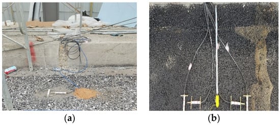
Figure 3.
Stress and strain gages in the test section. (a) The bottom of the AC layer. (b) The bottom of the SFP layer.
2.3. Setup of FE Model
The vehicle used in the Zhuzhou ART system is a single wheel and single axle, with three car boxes and six axles in the whole vehicle. Its tire width size is larger than the ordinary bus and the tire used is a 305/R70 22.5 radial tire, that is, the tire section width is 305 mm, the flat ratio is 70%, and the rim diameter is 22.5 inches, as shown in Figure 4. The FE model of tire was built according using the commercial finite element software ABAQUS (see Figure 5).
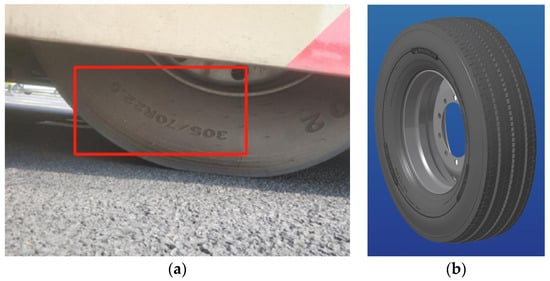
Figure 4.
Tire used in ART system. (a) Field picture. (b) A 305/R70 22.5 tire.
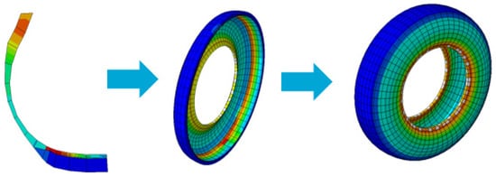
Figure 5.
The FEM model of the 305/R70 22.5 tire.
Based on the typical structural form of the test section of the ART pavement, a three-dimensional finite element model was established. The length of the model was 6 m, the width was 4 m, and the structural combination form of the ART pavement and the thickness of each structural layer are shown in Figure 6. The material parameters used in the model are listed in Table 2. It should be noted that the modulus of SFP-13 and AC-13 were obtained by interpolating the tested modulus values, and the temperature was determined according to the temperature measured during the field test, namely 33 °C and 35 °C for SFP-13 and AC-13, respectively.
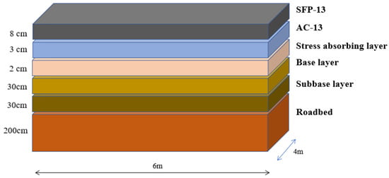
Figure 6.
The structure and dimensions of semi-flexible ART pavement.
Table 2.
The material parameters used in the model.
In the process of finite element model building, due to the limitation of storage space and available computational resources, the computational region is usually a small area of more limited size extracted from the whole continuous structure. Therefore, the setting of boundary conditions plays a decisive role in the accuracy and precision of the model. The artificially set boundary will cause the stress waves to reflect on the boundary, thus leading to a large deviation of the calculated results from the real value. The common method to solve this problem is to set a reasonable artificial boundary on the intercepted finite domain to simulate the interaction between the structure and the semi-infinite space of the foundation to prevent the outward propagating stress waves from reflecting back to the structural model [33]. Artificial boundary conditions can not only improve the accuracy of simulation results, but also save computational time and economic cost. Therefore, the finite element model established in this paper, except for the longitudinal boundary on the left side, which is set as a symmetric constraint, the rest of the boundaries, including the cross sections at both ends of the model and the longitudinal boundary at the edge of the roadbed on the right side of the model, are set as three-dimensional consistent viscoelastic artificial boundaries (see Figure 7).
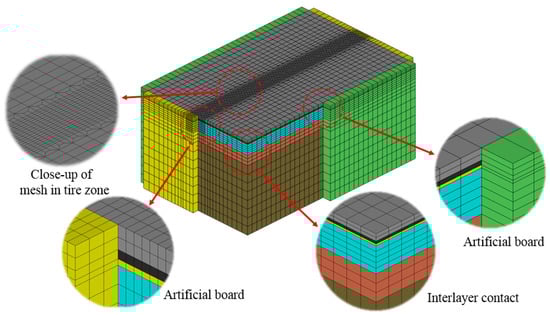
Figure 7.
The FE model of semi-flexible ART pavement.
The three-dimensional consistent viscoelastic artificial boundary simulates the damping effect of the infinite boundary by setting normal and tangential dampers at the boundary unit nodes and connecting them to the fixed boundary, forming a spring-damper system. The parameters of the springs and dampers are related to the physical parameters of the medium and the relative position of the point of action of the load to the boundary and are calculated by the following equations:
where
, are the normal and tangential stiffnesses of the spring, respectively;
, are the normal and tangential damping coefficients of the damper, respectively;
, are the tangential and normal correction coefficients, respectively;
is the distance from the wave source to the artificial boundary node;
, are the velocity of S-wave and P-wave, respectively, calculated as follows:
, , and are the shear modulus, stiffness, and mass density of the medium.
Numerous numerical calculations show that the viscoelastic artificial boundary has good robustness and the artificial boundary parameters αT and αN can be converged within a certain range of values. Table 2 shows the recommended values of parameters based on the numerical analysis by Jingbo Liu et al. [34,35]. The recommended values in Table 3 are used in this paper, i.e., αT and αN are 1.33 and 0.67, respectively.
Table 3.
The values of correction coefficients αT and αN.
2.4. Parameter Analysis
Using the tire–pavement coupled dynamics model, the influencing factors of the dynamic response of the semi-flexible ART pavement are analyzed. The influence law of vehicle operating conditions, such as vehicle axle weight, tire inflation pressure, and braking acceleration, and material parameters such as semi-flexible pavement material and asphalt mixture modulus on the dynamic response of ART pavement are studied.
Based on the tire–pavement coupled dynamics analysis model, the influence law of pavement structure combination form on the dynamic response of pavement is studied. By changing the structural parameters such as structural layer thickness and interlayer bonding state, the influence law of structural combination and interlayer constraint on the dynamic response of pavement is investigated to provide theoretical guidance to realize the optimal design of the ART pavement structure and material.
3. Results and Discussions
3.1. In Situ Test Results and FE Model Verification
- (1)
- Static analysis
The vehicle tire grounding area and grounding pressure are affected by a variety of factors such as tire type, material, inflation pressure, and pavement bearing capacity. In the field test of the Zhuzhou ART test section, the grounding area of the vehicle under the test section semi-flexible ART pavement conditions in the stationary state of the ART system was measured by the imprint method; the test result was 0.0429 m2. Limited by the field test conditions, the amplitude and distribution characteristics of the tire grounding pressure were not measured.
Based on the established tire–semi-flexible-ART-pavement contact model, tire grounding analysis was carried out and the simulation results of tire grounding area could be calculated by outputting the contact pressure cloud map on the tire surface, as shown in Figure 8. The simulation result of the tire grounding area under static load is 0.045 m2, which is in good agreement with the measured value of 0.0429 m2, and the distribution characteristics of the tire grounding pressure have the same pattern as the data recorded in the literature. Therefore, the simulation results preliminarily verify the reasonableness of the model parameters such as tire material parameters, inflation pressure, pavement material parameters, and contact parameters taken, and the validity of the tire–semi-flexible-ART-pavement coupling model.
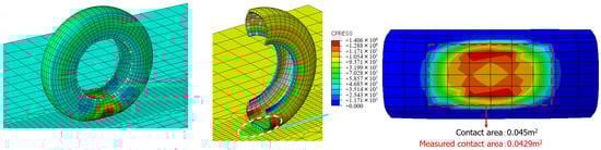
Figure 8.
Tire ground pressure of ART vehicle.
- (2)
- Dynamic analysis
Using the results of transient dynamics analysis, the nodes on the middle cross-section at the corresponding positions to the test monitoring points of the test section field test are selected to extract the simulated results of stress and strain and other dynamic responses of the ART pavement layers when the vehicle passes through. The correctness of the finite element model is further verified by comparing with the test results of the test section field test. Due to the limitation of model size and calculation time, only the dynamic response of the ART pavement structure during a single wheel pass is simulated for comparison and verification.
Figure 9 shows the comparison between the measured and simulated dynamic response of the SFP layer and the AC layer when the ART vehicle passes at a constant speed of 10 km/h, respectively. Due to different sampling frequency, for the single loading period, the sampling points recorded in the field test are less than the simulation data. However, the amplitude of simulated and measured values is in good agreement, indicating that the established tire–pavement coupling dynamic model is reliable.
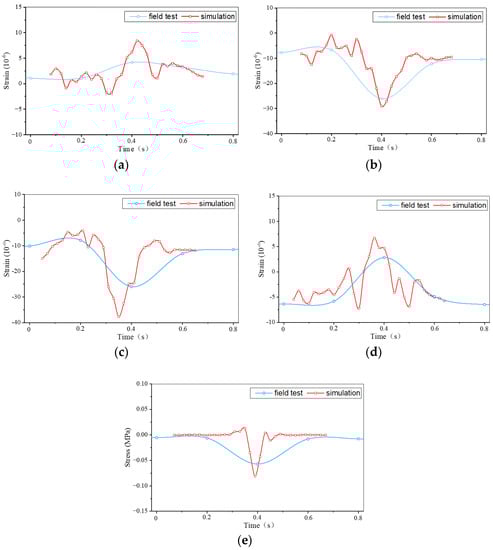
Figure 9.
The measured dynamic responses of ART pavement verses simulated value. (a) The longitudinal strain at the bottom of SFP layer. (b) The transverse strain at the bottom of SFP layer. (c) The longitudinal strain at the bottom of AC layer. (d) The transverse strain at the bottom of AC layer. (e) The vertical stress at the bottom of AC layer.
3.2. Distribution Features of Dynamic Responses under ART Train Load
Based on the validated explicit dynamics model of the tire–semi-flexible-ART-pavement coupling, the dynamic response distribution law and time-varying characteristics of the semi-flexible ART pavement under the vehicle moving load of the ART vehicle are analyzed. To eliminate the influence of the boundary conditions, the cross-section in the span of the wheel track zone in the model was selected as the interest path and the dynamic responses were extracted as the wheel loaded exactly above the cross-section.
Figure 10 shows the distribution of interlayer contact stress and dynamic deformation of the semi-flexible ART pavement under the tire load. Figure 11 and Figure 12 show the dynamic stress and strain clouds and transverse distribution curves at the bottom of SFP under wheel loading. It can be found that the tensile stresses/strains appear in the bottom surface of the SFP layer in the area directly below the tire in both the longitudinal direction (in the direction of travel) and the transverse direction (perpendicular to the direction of travel) under the wheel load. The maximum value of longitudinal tensile stress is 65 µε at the front edge of the tire grounding area and the maximum value of transverse tensile stress is 82 µε at the rear edge of the tire grounding area, which is consistent with the frequent occurrence of transverse cracks found in the test section.
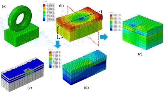
Figure 10.
The dynamic responses of ART pavement at the speed of 10 km/h. (a) Tire-pavement contact area. (b) Vertical displacement. (c) Vertical displacement along the transverse. (d) Longitudinal displacement along the longitudinal profile. (e) Interlayer contact pressure.
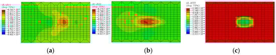
Figure 11.
The cloud of the dynamic strains of ART pavement at the speed of 10 km/h. (a) Longitudinal. (b) Transverse. (c) Vertical.
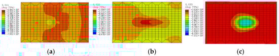
Figure 12.
The cloud of the dynamic stresses of ART pavement at the speed of 10 km/h. (a) Longitudinal. (b) Transvese. (c) Vertical.
3.3. The Effects of ART Train Operating Conditions
3.3.1. The Impact of Axle Load
On the basis of the standard axle load (45 kN) of the vehicle of the ART system, two operating conditions of no-load and overload are selected and the axle load is set to 35 kN and 50 kN, respectively. Figure 13 shows the distribution characteristics of the tire grounding pressure under the three axle load conditions and it can be found that with the increase of the axle load, the tire grounding pressure increases significantly and the area of the high-pressure zone in the grounding area increases.
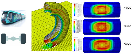
Figure 13.
Tire–pavement contact press under different axle load.
The simulation results of the dynamic response of the semi-flexible ART pavement under the three axle load conditions are shown in Figure 14. The simulation results show that the magnitude of the dynamic response of the semi-flexible ART pavement under the no-load condition decreases significantly and the changes of the compressive stress at the bottom of the asphalt layer and the longitudinal tensile strain at the bottom of the semi-flexible layer are the most significant. The effect of overload on the dynamic response of the semi-flexible ART pavement is smaller and the compressive stress at the bottom of the asphalt layer and the longitudinal/transverse tensile strain at the bottom of the semi-flexible layer increase slightly.
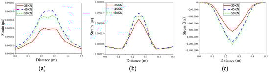
Figure 14.
The dynamic responses under different axle load. (a) The longitudinal strain at the bottom of SFP. (b) The transverse strain at the bottom of SFP. (c) The vertical stress at the bottom of AC.
3.3.2. The Impact of Tire Pressure
Based on the standard tire pressure (1.05 MPa) of the vehicle tire of the ART system, two operating conditions of underpressure and overpressure are selected and the tire inflation pressure is set to 0.8 MPa and 1.2 MPa, respectively. The distribution characteristics of the tire grounding pressure and the dynamic response of the semi-flexible ART pavement under the three tire pressure conditions are shown in Figure 15 and Figure 16, respectively. As the tire pressure increases, the tire grounding area shrinks and the grounding pressure distribution tends to be uniform, but the maximum value increases. The magnitude of the dynamic response of the semi-flexible ART pavement under the underpressure condition decreases significantly, in which the change of longitudinal/transverse tensile strain at the bottom of the semi-flexible ply is the most significant. The effect of overpressure on the transverse tensile strain at the bottom of the semi-flexible layer is significant. Since transverse strain is the dominant factor inducing the semi-flexible ART pavement, tire pressure control is critical to increase the stability of the ART pavement. Properly reducing the tire pressure can effectively improve the tensile environment at the bottom of the SFP layer.
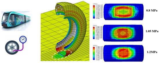
Figure 15.
Tire–pavement contact press under different tire pressure.
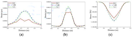
Figure 16.
The dynamic responses under different tire pressure. (a) The longitudinal strain at the bottom of SFP. (b) The transverse strain at the bottom of SFP. (c) The vertical stress at the bottom of AC.
3.4. The Effects of Pavement Material Propeties
Based on the validated coupled tire–pavement dynamics model, the influence of the modulus of the semi-flexible layer and the asphalt layer on the dynamic response of semi-flexible ART pavement is analyzed. Figure 17 shows the changes of the dynamic response of the ART pavement with different modulus values for the SFP layer and the AC layer. The simulation results show that the increase of the SFP modulus is beneficial to improve the stress state of the bottom and underlying layers and the increase of the AC modulus can improve the bottom tensile stress environment of the SFP layer, especially the longitudinal tensile stress environment.
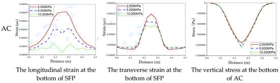
Figure 17.
The effects of materials modulus on the dynamic responses of ART pavement.
3.5. The Effects of Pavement Structural Composite
3.5.1. The Impact of Interlayer Conditions
Based on the structural characteristics of the semi-flexible ART pavement and the field research results, the interlayer bonding states of SFP-AC and GG-BL (base layer) are mainly considered. Three interlayer contact states are set up: interlayer complete contact, interlayer friction contact, and SFP-AC interlayer contact states completely continuous and GG-BL friction contact, respectively. Figure 18 shows the dynamic response distribution characteristics of the semi-flexible layer and the asphalt layer under the three interlayer contact states. The simulation results show that the interlayer bond between the SFP layer and the asphalt layer has a significant effect on the amplitude and distribution of the tensile stress at the bottom of the SFP layer and the bond state between GG and BL has a smaller effect.
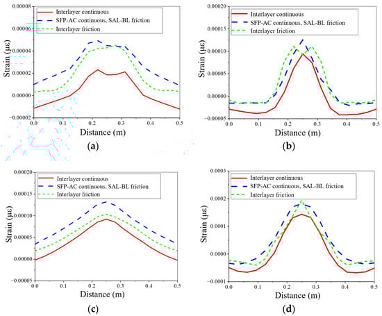
Figure 18.
The effects of interlayer conditions on the dynamic responses of ART pavement. (a) The longitudinal strain at the bottom of SFP. (b) The transverse strain at the bottom of SFP. (c) The longitudinal strain at the bottom of AC. (d) The transverse strain at the bottom of AC.
3.5.2. The Impact of SFP Layer Thickness
Figure 19 shows the dynamic response variation laws for the three pavement structure combination forms, namely 6 cm SFP + 6 cm AC, 8 cm SFP + 4 cm AC, and 10 cm SFP + 2 cm AC. The simulation results show that the transverse strain at the bottom of the semi-flexible layer and the vertical compressive stress at the bottom of the asphalt layer decrease with the increase of the thickness of the semi-flexible layer, while the transverse tensile strain at the bottom of the semi-flexible layer increases with the increase of the thickness of the semi-flexible layer; the rate of increase gradually increases with the increase of the thickness. The longitudinal tensile strain at the bottom of the semi-flexible layer is the smallest for the structure combination of 8 cm SFP + 4 cm AC and the longitudinal tensile strain at the bottom of the semi-flexible layer is the largest for 10 cm SFP + 2 cm AC, but the maximum value is still smaller than the transverse tensile strain. Therefore, for the semi-flexible ART pavement structure, the thicknesses of the semi-flexible layer and the asphalt concrete layer are not easy to differ too much under the premise of meeting the rutting resistance performance requirements. Considering the crack resistance performance only, the recommended structural combination form for Zhuzhou ART is 6 cm SFP + 6 cm AC.
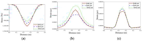
Figure 19.
The effects of structural composites on the dynamic responses of ART pavement. (a) The longitudinal strain at the bottom of SFP. (b) The transverse strain at the bottom of SFP. (c) The vertical stress at the bottom of AC.
4. Conclusions
This study first establishes the tire–pavement coupling dynamics model and uses the field test data recorded from the test section to verify the model. Then, on the validated model, the distribution of the dynamic responses of the semi-flexible ART pavement under the action of the ART vehicle are analyzed and a series of parameter studies are conducted to investigate the influences of vehicle operation state, ART pavement structure, and material properties. Finally, according to the results of the simulation analysis, the optimized design path of the semi-flexible ART pavement structure applicable to the ART system is analyzed. The main research conclusions are as follows.
(1) The coupled tire–ART pavement dynamics model established in this project can effectively simulate the dynamic response of the road surface under the vehicle load of the ART system.
(2) The horizontal forces generated under the influence of the bending basin and the driving force under the tire load and the discontinuity between layers are the main causes of the tension at the bottom of the SFP layer.
(3) Tire pressure of the axle load of the ART vehicle is an important factor affecting the dynamic response of the ART pavement, where tire pressure control is very critical to increase the stability of the ART pavement. Properly reducing the tire pressure can effectively improve the tensile environment at the bottom of the SFP layer.
(4) Under the action of braking force, significant tensile and compressive strains appear at the trailing and leading edges of tires, respectively, and the longitudinal tensile strains at the road surface generated by vehicle braking are important factors leading to transverse cracking of the semi-flexible ART pavement.
(5) The interlayer bonding between the SFP layer and the asphalt layer has significant influence on the amplitude and distribution of tensile stress at the bottom of the SFP layer and the bonding state of stress absorbing layer and base layer has less influence. For semi-flexible ART pavement structure, the thickness of the semi-flexible layer and the asphalt concrete layer is not easy to differ too much under the premise of meeting the requirements of rutting resistance performance.
Author Contributions
Conceptualization, B.P., S.L. and M.G.; methodology, S.L., H.Z. and M.G.; software, S.L.; investigation, B.P. and H.Z.; validation, S.L.; writing—original draft, S.L. and H.Z.; writing—review and editing, M.G. and J.Y.; resources, B.P.; project administration, B.P. All authors have read and agreed to the published version of the manuscript.
Funding
This research was funded by the Natural Science Foundation of Jiangsu Province of China (Grant Number No. BK20220419, BK20210058) and the Science and Technology Progress and Innovation Project of Hunan Provincial Department of Transportation (Grant Number No. 202111).
Institutional Review Board Statement
Not applicable.
Informed Consent Statement
Not applicable.
Acknowledgments
The authors would like to thank Lei Jiang from Sobute New Materials Co., Ltd. and Xuexin Zhang Beijing Urban Construction Group Co., Ltd. for their contribution to field test and formal analysis.
Conflicts of Interest
The authors declare that they have no known competing financial interests or personal relationships that could have appeared to influence the work reported in this paper.
References
- Liu, W.; Zhang, C.; Wang, F.; Zhang, J.; Wang, L. Study on the Selection of Middle Urban Mass Rapid Transit System and Adaptability Analysis. J. Internet Technol. 2021, 22, 605–613. [Google Scholar]
- Newman, P.; Hargroves, C.; Davies-Slate, S.; Conley, D.; Verschuer, M.; Mouritz, M.; Yangka, D. The trackless tram: Is it the transit and city shaping catalyst we have been waiting for? J. Transp. Technol. 2019, 9, 31–55. [Google Scholar] [CrossRef]
- Li, T.; Zhang, S.; Xiao, G.; Wang, M.; Zhong, H.; Feng, J. Brake Instability Dynamic Model and Active Control Strategy for a Multiunit Articulated Rubber-Wheel Autonomous Rail Rapid Transit System. Sustainability 2022, 14, 14531. [Google Scholar] [CrossRef]
- Bachtiar, R.R.; Septione, A.D.; Larasati, N.A.; Perwira, D.A.; Pribadi, F.S.; Nurtanto, M.; Subramaniam, T.S. Autonomous Rail Rapid Transit (ART) Prototype Concept Using Wireless Charging System with Electromagnetic Induction Coupling. J. Railw. Transp. Technol. 2022, 1, 1–12. [Google Scholar]
- Wang, C.; Zhang, J.; Zhou, H.; Lu, H. Analysis of the running quality and road friendliness of the virtual track train in multiple running stages between stations. J. Mech. Sci. Technol. 2022, 36, 593–605. [Google Scholar] [CrossRef]
- Wang, C.; Zhang, J.; Zhou, H. Analysis of Tire-Pavement Contact Morphology Characteristics during the Virtual Track Train Maneuvering. Adv. Civ. Eng. 2022, 2022, 1285552. [Google Scholar] [CrossRef]
- Wang, C.; Zhang, J.; Zhou, H.; Lu, H. Dynamic Response and Permanent Deformation Analysis of Asphalt Pavement under the Virtual Rail Train. Tongji Daxue Xuebao/J. Tongji Univ. 2021, 49, 60–66. [Google Scholar]
- Cai, X.; Huang, W.; Wu, K. Study of the Self-Healing Performance of Semi-Flexible Pavement Materials Grouted with Engineered Cementitious Composites Mortar based on a Non-Standard Test. Materials 2019, 12, 3488. [Google Scholar] [CrossRef]
- Hassani, A.; Taghipoor, M.; Karimi, M.M. A state of the art of semi-flexible pavements: Introduction, design, and performance. Constr. Build. Mater. 2020, 253, 119196. [Google Scholar] [CrossRef]
- Pratelli, C.; Betti, G.; Giuffre, T.; Marradi, A. Preliminary In-Situ Evaluation of an Innovative, Semi-Flexible Pavement Wearing Course Mixture Using Fast Falling Weight Deflectometer. Materials 2018, 11, 611. [Google Scholar] [CrossRef]
- Cai, X.; Zhang, H.; Zhang, J.Y.; Chen, X.H.; Yang, J.; Hong, J.X. Investigation on reinforcing mechanisms of semi-flexible pavement material through micromechanical model. Constr. Build. Mater. 2019, 198, 732–741. [Google Scholar] [CrossRef]
- Ling, S.L.; Chen, Z.B.; Sun, D.Q.; Ni, H.T.; Deng, Y.; Sun, Y. Optimal Design of Pouring Semi-Flexible Pavement via Laboratory Test, Numerical Research, and Field Validation. Transp. Res. Rec. 2022, 2676, 479–495. [Google Scholar] [CrossRef]
- Zarei, S.; Ouyang, J.; Yang, W.T.; Zhao, Y.Q. Experimental analysis of semi-flexible pavement by using an appropriate cement asphalt emulsion paste. Constr. Build. Mater. 2020, 230, 116994. [Google Scholar] [CrossRef]
- Alae, M.; Zarei, S.; Ouyang, J.; Xiao, F.P. Prediction of top-down crack resistance in semi-flexible pavements under coupling effect of rutted surface and temperature gradient. Int. J. Pavement Eng. 2022. [Google Scholar] [CrossRef]
- Guo, X.G.; Hao, P.W. Influential Factors and Evaluation Methods of the Performance of Grouted Semi-Flexible Pavement (GSP)-A Review. Appl. Sci. 2021, 11, 6700. [Google Scholar] [CrossRef]
- Gong, M.H.; Xiong, Z.J.; Deng, C.; Peng, G.; Jiang, L.; Hong, J.X. Investigation on the impacts of gradation type and compaction level on the pavement performance of semi-flexible pavement mixture. Constr. Build. Mater. 2022, 324, 126562. [Google Scholar] [CrossRef]
- Xiong, Z.J.; Gong, M.H.; Hong, J.X.; Deng, C. The Influential Factors of Semi-Flexible Pavement Cracking Performance. J. Wuhan Univ. Technol.-Mater. Sci. Ed. 2022, 37, 953–962. [Google Scholar] [CrossRef]
- Hu, C.; Zhou, Z.G.; Chen, G.H. Effects of different types of acid rain on water stability of asphalt pavement. Constr. Build. Mater. 2022, 322, 126308. [Google Scholar] [CrossRef]
- Bharath, G.; Shukla, M.; Nagabushana, M.N.; Chandra, S.; Shaw, A. Laboratory and field evaluation of cement grouted bituminous mixes. Road Mater. Pavement Des. 2020, 21, 1694–1712. [Google Scholar] [CrossRef]
- Cai, J.; Pei, J.; Luo, Q.; Zhang, J.; Li, R.; Chen, X. Comprehensive service properties evaluation of composite grouting materials with high-performance cement paste for semi-flexible pavement. Constr. Build. Mater. 2017, 153, 544–556. [Google Scholar] [CrossRef]
- Hong, J.; Wang, K.; Xiong, Z.; Gong, M.; Deng, C.; Peng, G.; Zhu, H. Investigation into the freeze–thaw durability of semi-flexible pavement mixtures. Road Mater. Pavement Des. 2020, 21, 2198–2214. [Google Scholar] [CrossRef]
- Ma, X.; Jiang, J.; Zhao, Y.; Wang, H. Characterization of the interconnected pore and its relationship to the directional permeability of porous asphalt mixture. Constr. Build. Mater. 2021, 269, 121233. [Google Scholar] [CrossRef]
- Zarei, S.; Ouyang, J.; Zhao, Y.A. Evaluation of fatigue life of semi-flexible pavement with cement asphalt emulsion pastes. Constr. Build. Mater. 2022, 349, 128797. [Google Scholar] [CrossRef]
- Li, S.; Ni, F.; Dong, Q.; Zhao, Z.; Ma, X. Effect of filler in asphalt mastic on rheological behaviour and susceptibility to rutting. Int. J. Pavement Eng. 2021, 22, 87–96. [Google Scholar] [CrossRef]
- Dong, Q.; Zhao, X.; Chen, X.; Ma, X.; Cui, X. Long-term mechanical properties of in situ semi-rigid base materials. Road Mater. Pavement Des. 2021, 22, 1692–1707. [Google Scholar] [CrossRef]
- Xiong, H.; Han, J.F.; Wang, J.; Ren, Q.; Wu, L.B. Application of high viscosity-high modulus modified asphalt concrete in bus rapid transit station pavement-A case study in Chengdu, China. Case Stud. Constr. Mater. 2022, 17, e01337. [Google Scholar] [CrossRef]
- Li, G.S.; Xiong, H.; Ren, Q.; Zheng, X.G.; Wu, L.B. Experimental Study and Performance Characterization of Semi-Flexible Pavements. Coatings 2022, 12, 241. [Google Scholar] [CrossRef]
- Du, Y.F.; Chen, J.Q.; Han, Z.; Liu, W.Z. A review on solutions for improving rutting resistance of asphalt pavement and test methods. Constr. Build. Mater. 2018, 168, 893–905. [Google Scholar] [CrossRef]
- Xu, J.; Kong, C.; Xu, T. Displacemental and mesomechanical responses of semi-flexible pavement based on discrete element method. Int. J. Pavement Res. Technol. 2021, 15, 1484–1497. [Google Scholar] [CrossRef]
- Zarei, S.; Alae, M.; Ouyang, J.; Zhao, Y. Rutting and surface-initiated cracking mechanisms of semi-flexible pavements with cement asphalt emulsion pastes. Int. J. Pavement Eng. 2022. [Google Scholar] [CrossRef]
- Dong, Z.; Ma, X. Analytical solutions of asphalt pavement responses under moving loads with arbitrary non-uniform tire contact pressure and irregular tire imprint. Road Mater. Pavement Des. 2018, 19, 1887–1903. [Google Scholar] [CrossRef]
- Machemehl, R.B.; Wang, F.; Prozzi, J.A. Analytical study of effects of truck tire pressure on pavements with measured tire–pavement contact stress data. Transp. Res. Rec. 2005, 1919, 111–120. [Google Scholar] [CrossRef]
- Liu, S.; Chen, X.; Ma, Y.; Yang, J.; Cai, D.; Yang, G. Modelling and in-situ measurement of dynamic behavior of asphalt supporting layer in slab track system. Constr. Build. Mater. 2019, 228, 116776. [Google Scholar] [CrossRef]
- Jingbo, L.; Yin, G.; Yixin, D. Consistent viscous-spring artificial boundaries and viscous-spring boundary elements. Chin. J. Geotech. Eng. 2006, 28, 1070–1075. [Google Scholar]
- Yin, G.U.; Jingbo, L.I.U.; Yixin, D.U. 3D Consistent Viscous-spring Artificial Boundary and Viscous-spring Boundary Element. Eng. Mech. 2007, 24, 31–37. [Google Scholar]


Disclaimer/Publisher’s Note: The statements, opinions and data contained in all publications are solely those of the individual author(s) and contributor(s) and not of MDPI and/or the editor(s). MDPI and/or the editor(s) disclaim responsibility for any injury to people or property resulting from any ideas, methods, instructions or products referred to in the content. |
© 2023 by the authors. Licensee MDPI, Basel, Switzerland. This article is an open access article distributed under the terms and conditions of the Creative Commons Attribution (CC BY) license (https://creativecommons.org/licenses/by/4.0/).