Article

Effect of Heat Treatment on the Microstructure and Mechanical Properties of Rotary Friction Welded Dissimilar IN718 to SS304L Alloys

by
Perumandla Pavan
1,
Mahesh Kumar Talari
1,
Nagumothu Kishore Babu
1,*,
Ateekh Ur Rehman
2,* and
Prakash Srirangam
3
1
Department of Metallurgical and Materials Engineering, National Institute of Technology, Warangal 506004, India
2
Department of Industrial Engineering, College of Engineering, King Saud University, Riyadh 11451, Saudi Arabia
3
Warwick Manufacturing Group, University of Warwick, Coventry CV4 7AL, UK
*
Authors to whom correspondence should be addressed.
Appl. Sci. 2023, 13(6), 3584; https://doi.org/10.3390/app13063584
Submission received: 11 February 2023 / Revised: 8 March 2023 / Accepted: 9 March 2023 / Published: 10 March 2023
(This article belongs to the Special Issue Metal Additive Manufacturing and Welding)

Abstract

:

Featured Application

Rotary friction welding of AA7075 T6511 to AA5083 H116 Aluminum alloys.

Abstract

The present study investigated the effect of heat treatment (pre- and post-weld) on the microstructure and mechanical properties of an SS304L/IN718 dissimilar rotary friction welded alloy. Optical and scanning electron micrographs of the dissimilar rotary friction welded SS304L/IN718 joints in solution-treated (ST), solution-treated and aged (STA), and post-weld heat treatment (PWHT) conditions revealed defect-free welds. Furthermore, various zones were observed across the weld region, namely the fully deformed zone (FDZ), thermomechanical affected zone (TMAZ), heat affected zone (HAZ), and base material (BM). Among the SS304L/IN718 dissimilar friction welds with different heat treatment conditions (prior ST and STA, PWHT), the PWHTed dissimilar welds exhibited excellent mechanical properties, which could be attributed to the formation of the strengthening precipitates γ′ and γ″ during double aging in PWHT. In contrast, the mechanical properties were found to be the poorest in the STA condition, possibly due to the dissolution of the strengthening precipitates γ′ and γ″ during friction welding. It was observed that the SS304L/IN718 dissimilar friction welds in the ST and STA conditions failed in the HAZ of the SS304L side, away from the weld interface, indicating that the weld region was stronger than the weakest base metal (SS304L) in the various joints.

1. Introduction

Due to its excellent properties, the high-strength superalloy Inconel718 finds extensive use in high-temperature applications, such as turbine blades, jet engines, gas turbine applications, and disk materials. These properties include good weldability, corrosion resistance, oxidation resistance, excellent resistance to crack formation, and high creep strength at elevated temperatures [1,2]. The primary strengthening mechanism in this alloy results from coherent disc-shaped particles of γ″ (Ni3Nb) precipitates. The good weldability of these superalloys is attributed to their resistance to strain age cracking, which arises from the sluggish precipitation kinetics of the γ″ phase. This slow age-hardening effect results in a relatively high ductility and low strength in the HAZ during the initial aging treatment, which allows the residual stresses to relax and reduces the propensity for strain–age cracking [3].
Austenitic stainless steels are extensively used in nuclear and petrochemical environments, due to their excellent mechanical performance at higher temperatures. These steels also possess good corrosion and oxidation resistance. These steels are classified as “L” grades, “straight” grades, or “H” grades, based on their carbon content. The L grades have a carbon content of 0.03%, the straight grades have a carbon content of 0.03–0.08%, and the H grades have a carbon content of 0.04–0.10%. The high carbon content in H grades makes them much harder and more wear-resistant. Due to the additional carbon content, the H grades can retain their strength and hardness at higher temperatures, which makes them suitable for high-temperature applications. However, an increase in carbon content also results in poor weldability of the steel. The low carbon percentage of L grades is explicitly designed to increase weldability. Low-carbon stainless steels such as SS304L are commonly used to avoid intergranular corrosion [4].
Ni-Fe superalloys are used for various structural applications in aerospace, nuclear power plants, and chemical industries. Joining these alloys to stainless steels is common, and the demand for economical and efficient materials frequently involves joining dissimilar metals. Inconel718 alloy is expensive, and a bimetallic junction with low-cost components is economical. Steel is a high-strength, low-cost structural material [5]. SS304L is the most frequently used austenitic stainless steel, known for its excellent strength and corrosion resistance properties. Although bolts and mechanical fasteners can be used to join superalloys with stainless steel 304L (alloy steels) for different applications, welding techniques are preferred for creating dissimilar metallurgical joints, because mechanical joints tend to exhibit poor fatigue performance. Conventional fusion welding techniques have many problems, such as Laves phase, boron/niobium segregation, and micro-fissures (liquation cracking) in the fusion zone or HAZ of IN718 welds [3]. Laves is a brittle intermetallic phase that negatively impacts the mechanical properties. To avoid the solidification-related problems associated with fusion welding, solid-state welding processes such as friction welding are preferable. Welds joined by friction welding are free of porosity, segregation, and liquation cracking, as melting and solidification are not involved in this process. Reddy et al. [6] compared the effects of welding processes on the microstructure and mechanical properties of dissimilar austenitic (AISI 304)-ferritic (AISI 430) stainless steel weld joints. They found that friction welding dissimilar AISI304/AISI 430 welds displayed greater pitting corrosion resistance compared to welds prepared using fusion welding techniques (GTAW, EBW). This was owing to the low occurrence of carbides in the friction weld microstructure in similar and dissimilar welds.
Standard heat treatment of superalloy Inconel 718 consists of solution treatment and aging. Damodaram et al. [3] reported that friction-welded alloy 718 joints, prior to STA process, friction-welded alloy 718 joints displayed lower hardness and tensile properties in the weld zone compared to the BM. The IN718 friction welds prepared from ST showed a fine grain structure in the weld zone due to DRX, which enhanced the hardness. Kong et al. [7] reported that PWHT improved the microhardness and tensile strength properties of friction welds compared to the as-welded condition, because of the modification of the microstructure and the formation of γ′ and γ″ precipitates. IN718 is a highly alloyed material that is prone to alloying element segregation and formation of unsolicited phases at the grain boundaries, which are high-energy sites. Xiao et al. [8] utilized a homogenization heat treatment at 1066 °C to reduce boron (B) segregation at grain boundaries in cast IN718. This treatment increased the resistance to HAZ microfissuring, while significantly decreasing the volume percentage of NbC and Laves phases.
Friction welding parameters are crucial to the welding process, including spindle rotation speed, friction pressure, upset pressure, friction time, and burn-off length. Anitha et al. [5] examined the influence of friction welding parameters on dissimilar IN718/SS410 rotary friction welds, by varying the rotation speed and friction pressure. They found that increasing the rotating speed and friction pressure enhanced the tensile strength values. The maximum tensile strength of 718 MPa was attained at a rotating speed of 1500 rpm and a friction pressure of 189 MPa. Anandaraj et al. [9] investigated the mechanical and metallurgical properties of dissimilar IN718 to SS410 rotary friction welded joints. They observed that the process parameters, such as forging time (10 s), friction pressure (220 MPa), and rotating speed (1300 rpm), could be used to optimized the maximum tensile strength (652 MPa). Murali Mohan et al. [10] reported that the IN718-SM45C dissimilar friction joints displayed the highest fatigue and tensile properties at 10 s of heating time. A further increase in heating time reduced the mechanical performance. Wang et al. [11] reported that rapid thermal and mechanical stress cycles altered the microstructure of IN718 friction welded joints. They also found that the upset pressure during welding severely affected the weld zone width, with a higher upset pressure yielding a narrower weld zone width. The friction weld zone of alloy 718 revealed an average grain size of about 2–5 µm in the DRX zone near the weld interface. Precipitate dissolution can occur in the weld zone and TMAZ/HAZ of the IN718 alloy welds, due to the high temperatures encountered during friction welding exceeding the solvus temperatures of the strengthening precipitates.
Kirik et al. [12] investigated the influence of process parameters on the microstructure and mechanical properties of friction-welded joints between AISI 1040 and AISI 304L steel. Four microstructurally unique zones were identified in the weldment, namely, the friction-affected zone (FDZ), thermo-mechanically affected zone (TMAZ), heat-affected zone (HAZ), and base metal (BM). The width of the FDZ and HAZ was mainly influenced by the friction time and rotational speed. The tensile strength of the dissimilar continuous drive friction-welded joint was increased by increasing the rotation speed and decreasing the friction time. Ozdemir et al. [13] studied the mechanical properties of dissimilar AISI 304L/AISI 4340 steel friction-welded joints as a function of rotation speed. They concluded that sufficient welding strength could be achieved by keeping the friction time as short as possible, while the friction pressure, forging pressure, and rotation speed should be as large as feasible. Nelson et al. [14] investigated the mechanical properties and grain structure development of alloy 718 tube joints produced using the rotary friction welding process. The grain structure in the weld’s recrystallization zone resulted from the competition between dynamic recrystallization (DRX) and grain boundary sliding (GBS), controlled by the local deformation condition. Decreasing the rotation rate resulted in a smaller grain size in the weld’s nugget zone, necessitating a lower applied force to enable GBS. The tensile strength of the IN718 alloy weld joint could be enhanced by optimizing the friction welding parameters and post-weld heat treatment (PWHT) conditions.
Sayed et al. [15] investigated the effect of various cooling methods on the performance of steel in the welding processes. Their study compared the use of water, air, and oil as cooling agents during the welding process and evaluated the resulting microstructure, hardness, and tensile strength of the welded metal. The results indicated that the cooling method significantly impacted the microstructure and mechanical properties of the welded steel, with the use of water showing the most favorable results, in terms of both microstructure and mechanical properties. The mechanical properties of the welded steel material depened on the methods used for cooling the material after welding [15]. Hatherly et al. [16] reported that TMAZ exhibited serrated necklace-shaped, deformed grain boundaries, with fine grains surrounding the original deformed grains. A variation in microstructure was observed between the weld zone and the TMAZ, due to recrystallization. At the interface, fully recrystallized grains developed, but the recrystallization in the TMAZ was restricted to elongated grains.
Mary and Jahazi et al. [17] investigated the microstructure evolution and process optimization of linear friction welded IN718 joints. They observed a decrease in hardness in the TMAZ on the hardness plot (334 HV to 250 HV), which was attributed to the dissolution of γ′/γ″ precipitates and grain coarsening during the rotary friction welding process, owing to high temperatures throughout the process. Mahadevan et al. [18] investigated the mechanical property evolution during dissimilar friction welding of IN600 to SS304L. They found that the welds displayed a higher ultimate tensile strength (UTS-500 MPa) and yield strength (YS-315 MPa) than the base materials. Reddy et al. [19] investigated the dissimilar metal friction welding of austenitic-ferritic stainless steel and observed that the dissimilar metal welds’ notch tensile strength (NTS: 600–697 MPa) properties were superior to those of the ferritic stainless steel parent metal (NTS: 547–590 MPa).
The joining of stainless steel (SS304L) with dissimilar materials such as titanium, ferritic stainless steels, Inconel600, and titanium with nickel interlayer has been widely investigated, in terms of strength and metallurgical characteristics, and a substantial amount of literature is available on friction welding methods [18,19,20,21]. However, to the best of the author’s knowledge, the literature on the joining of low carbon grade austenitic stainless steel (304L) to IN718 by rotary continuous friction welding is limited. The present study aimed to evaluate the effect of heat treatments on the microstructural and mechanical properties of rotary friction welded dissimilar joints of Inconel 718 to 304L austenitic stainless steel.

2. Experimental Procedure

Austenitic stainless steel 304L and Inconel 718 cylindrical rods, with a diameter of 15 mm and length of 100 mm, were employed as parent materials in this study. Table 1 presents the nominal compositions of the parent materials.
The Inconel 718 alloy was subjected to two different pre-weld heat treatments: ST and STA. Pre-welded IN718 samples in ST and STA conditions were friction welded to SS304L, and these samples were designated SS304L/IN718 ST and SS304L/IN718 STA, respectively. During the solution treatment (ST), the samples were heated to 990 °C and held for 1 h and 15 min, followed by air cooling to room temperature. The STA treatment consisted of (i) solution treatment followed by (ii) two-step ageing. The ageing of solution-treated samples consisted of a first step aging at 720 °C for 8 h, followed by furnace cooling to 620 °C; and then a second step of aging at 620 °C for 7.5 h, followed by air cooling to room temperature. The welded dissimilar SS304L/IN718 ST joints were subjected to PWHT (direct ageing) and were designated as SS304L/IN718 PWHT. PWHT involved a first aging step at 720 °C for 8 h, followed by furnace cooling to 620 °C; and then a second aging step at 620 °C for 7.5 h, followed by air cooling to room temperature. The typical solution treatment and two-step aging cycle are shown in Figure 1.
The friction welding machine used is capable of high precision and good weld parameter repeatability. The joints were made with hydraulically operated continuous drive friction welding equipment (ETA Technologies Pvt Ltd., Bangalore, India) with a capacity of 100 KN. During the welding process, the IN718 was fixed into the stationary chuck, the and SS304L was fixed into the rotating chuck. Table 2 shows the optimal parameters used during the welding process.
The dissimilar rotary friction welded joints were sectioned and embedded in bakelite before being mechanically polished with 600 to 2000-grit SiC sheets. Cloth polishing with 0.5–1 μm diamond paste was used to finely polish the surface. A macroscopic examination of the welded samples was carried out with a stereomicroscope. The microstructural investigation was carried out with an optical microscope (Motic, Model: AE2000 MET, New York, NY, USA) and a scanning electron microscope (TESCAN, Model: VEGA 3 LMU, Brno, Czech Republic) with a connected Energy-dispersive X-ray spectroscope (EDS). The parameters used for this examination were 20 kV accelerating voltage, with a working distance of 10 mm. Grain size measurements were taken at three to four distinct areas in the FDZ using a line intercept method and higher magnification micrographs. The etchants used to reveal the microstructures of the weldment are shown in Table 3.
A Vickers microhardness tester (Shimadzu, HMV 2T E, Kyoto, Japan) was used to conduct a hardness survey across the weldment in the transverse direction. The measurements were made using a diamond pyramid indenter under a load of 200 g and a dwell time of 15 s, with 0.5 mm intervals between the indentations. The tensile specimens were fabricated in as-welded and PWHT conditions, according to American Society for Testing and Materials (ASTM) standards, and their dimensions are shown in Figure 2. The tensile tests were performed at room temperature using a universal testing machine (Zwick/Roell, Model—Kappa 100SS-CF, Fürstenfeld, Austria) with an attached extensometer (Epsilon technology corp, Jackson, WY, USA) at a displacement rate of 1 mm/min.

3. Results and Discussion

3.1. Base Materials

Figure 3a,b show optical and scanning electron micrographs of the SS304L BM. Micrographs revealed equiaxed austenitic grains, and the average grain size was 30 ± 9 µm.
Figure 4a,b show optical and scanning electron micrographs of the IN718 ST base metal, respectively. The microstructure revealed equiaxed grains with annealing twins. The average grain size of the IN718 ST alloys was 19 ± 3 µm.
Figure 4b shows numerous δ-particles randomly dispersed in the grain boundaries, which were confirmed to be δ (Ni3Nb) using energy dispersive X-ray analysis (EDAX), as depicted in Figure 4c. These δ (Ni3Nb) particles had a high dissolution temperature (1030 °C) and did not dissolve during the solutionizing process.
Figure 5a,b show optical and scanning electron micrographs of IN718 STA base metal, respectively. The micrographs revealed equiaxed grains with annealing twins, and the average grain size of the IN718 STA alloy was 24 ± 7 µm. Figure 5b also shows numerous randomly dispersed δ (Ni3Nb) fine particles at the grain boundaries and within the grains. When comparing the microstructures of the IN718 ST and IN718 STA, it was observed that the grain size of the IN718 STA samples was coarser, due to prolonged exposure to high temperatures and the sluggish nature of the γ″ precipitation process during aging.

3.2. Macrostructure Examination

Photographs of the SS304L/IN718 ST and SS304L/IN718 STA dissimilar friction welded joints are depicted in Figure 6a,b, respectively. A macrograph of the friction-welded dissimilar joint of SS304L/IN718 ST is shown in Figure 7. The macro examination revealed a defect-free weld joint, with a sound flash caused by the plasticization of the metal at the weld interface. The formation of the flash on both sides was lopsided, due to the different mechanical properties of the dissimilar materials being joined [22]. On the 304L side, the weld flash was dominant, whereas the Inconel 718 had a less pronounced effect on the flash formation, indicating that SS304L was more deformed at a high strain at the weld interface [23]. This was because IN718 is much harder than SS304L at friction welding temperatures [24]. Furthermore, a sharp reduction in the flow stress in the SS304L at high temperatures during friction welding softened the alloy compared to the IN718 side. Moreover, the SS304L’s poor thermal conduction characteristics compared to the IN718 led to the rapidly rising temperature on its side of the joint.

3.3. Microstructure Characterization

Figure 8 and Figure 9 show the optical microstructures of the dissimilar as-welded SS304L/IN718 rotary friction welded joints with prior ST and STA treatments, respectively. The optical micrographs of the weld cross sections reveal four distinct zones as they move from the weld to the base metal on each side (SS304L/IN718) of the weldments: FDZ, TMAZ, HAZ, and the unaffected BM, respectively. The FDZ was located adjacent to the weld interface on both the IN718 and SS304L sides of the SS304L/IN718 ST weldment (Figure 8a,h). This is distinguishable from all other zones by its blackish color at low magnification. The FDZ on the SS304L side of the SS304L/IN718 ST weldment was ~0.33 mm wide, while the FDZ on the IN718 side was ~0.40 mm. Finer grains were observed in the FDZ on the SS304L and IN718 sides of the SS304L/IN718 ST weldment at higher magnification. This was due to the severe plastic deformation of the FDZ, which generated highly strained grains with a high dislocation density [25]. The highly deformed FDZ region dynamically recrystallized due to the heat generated during welding, resulting in fully equiaxed fine grains in the microstructure [26]. Similar observations were made by Anitha et al. during dissimilar rotary friction welding of IN718 to SS410 [5]. The average grain size of the FDZ in the SS304L/IN718 ST weldment was 12 ± 3 µm on the SS304L side and 6 ± 2 µm on the IN718 side. Elongated grains were observed on both the SS304L (Figure 8g) and IN718 (Figure 8b) sides of the SS304L/IN718 ST weldment adjacent to the FDZ; these regions are referred to as TMAZ. This zone was partially deformed and showed elongated grains orientated in a “necklace” pattern [3]. Due to the lower heat and plastic deformation in TMAZ compared to the FDZ, partial recrystallization occurred. Finer recrystallized grains formed along the elongated grain boundaries [16], resulting in a bimodal grain structure in the TMAZ. Similar findings were made by Damodaram et al. [27] regarding the TMAZ zone in friction-welded alloy 718 joints.
Furthermore, Zhao et al. [28] studied the influence of Nb-V microalloying on the hot deformation characteristics and microstructures of Fe-Mn-Al-C austenitic steel in hot compression tests at various strain rates. For a strain of 0.7, they found necklace-like distorted grains at temperatures below 1050 °C, whereas completely recrystallized grains were found at and above 1050 °C. In the SS304L/IN718 ST weldment, the average grain size of the TMAZ was 27 ± 9 µm on the SS304L side, and 14 ± 6 µm on the IN718 side. HAZ was observed on both the SS304L (Figure 8f) and IN718 (Figure 8c) sides of the SS304L/IN718 ST weldment adjacent to the TMAZ. As it is far from the weld interface, this zone experienced less heat and no plastic deformation compared to TMAZ and FDZ zones. Therefore, the HAZ did not undergo recrystallization, and the grains that were formed in this zone were coarser and had a unimodal grain structure. The average grain size values of the HAZ were 36 ± 9 µm and 25 ± 5 µm on the SS304L and IN718 sides, respectively. BM was observed on both the SS304L (Figure 8e) and IN718 (Figure 8d) sides of the SS304L/IN718 ST weldment adjacent to the HAZ. As the temperature in this area was very low for microstructural changes, the BM had an unaffected base microstructure of IN718 ST and SS304L.
Figure 9 depicts the optical microstructures of an as-welded SS304L/IN718 STA dissimilar rotary friction welded joint. On both the IN718 and SS304L sides of the SS304L/IN718 STA weldment (Figure 9a,h), the FDZ was observed next to the weld interface with an average grain size of 7 ± 1 µm on the IN718 side and 10 ± 3 µm on the SS304L side. The FDZ was observed next to the weld interface on both the IN718 and SS304L sides of the SS304L/IN718 STA weldment (Figure 9a,h), with an average grain size of 7 ± 1 µm on the IN718 side and 10 ± 3 µm on the SS304L side. The TMAZ was observed beside the FDZ (Figure 9b,g), with an average grain size of 19 ± 4 µm on the IN718 side and 27 ± 9 µm on the SS304L side. The HAZ was observed adjacent to the TMAZ (Figure 9c,f), with an average grain size of 28 ± 7 µm on the IN718 side and 37 ± 9 µm on the SS304L side.
To summarize, the zones and mechanisms of zone formation in the dissimilar friction-welded SS304L/IN718 ST were identical to those in the dissimilar friction-welded SS304L/IN718 STA. When comparing the SS304L sides of the SS304L/IN718 ST and SS304L/IN718 STA weldments, it can be observed that they had almost the same grain sizes in both the SS304L/IN718 ST and SS304L/IN718 STA weldments, in all zones except the FDZ (i.e., TMAZ, HAZ, and BM). This can be attributed to the fact that SS304L is not heat-treatable. Furthermore, the FDZ grain size on the SS304L side of the SS304L/IN718 ST weldment was coarser than that of the SS304L/IN718 STA weldment. When comparing the SS304L sides of SS304L/IN718 ST and STA, it was observed that the SS304L side of SS304L/IN718 STA experienced higher deformation than the SS304L side of SS304L/IN718 ST. Thus, the relatively higher strain hardening in the FDZ of the SS304L side of SS304L/IN718 STA resulted in finer recrystallized grains compared to the SS304L side of SS304L/IN718 ST weldment.
When comparing the IN718 side of the SS304L/IN718 ST and SS304L/IN718 STA weldments, significant grain coarsening was observed in all zones (FDZ, TMAZ, HAZ, BM) of the SS304L/IN718 STA weldments. The IN718 side of SS304L/IN718 ST underwent higher deformation and strain hardening compared to the SS304L/IN718 STA weldment, resulting in finer recrystallized grains in the FDZ of the IN718 side of the SS304L/IN718 ST weldment. The average grain sizes are summarized in Table 4. Figure 10 and Figure 11 show scanning electron micrographs of the weld interface of the rotary friction welded dissimilar SS304L/IN718 ST and SS304L/IN718 STA weldments, respectively. The δ- phase particles in the IN718 were dissolved at the weld interface during friction welding, due to the high temperatures developed during the process. Faster cooling rates during the welding arrested the reprecipitation of the second phase [29]. It is notable that the intermixing zone was prominently observed for the SS304L/IN718 ST weldment, while SS304L/IN718 STA showed no intermixing zone. IN718 in the ST condition was softer and underwent mechanical mixing during welding with SS304L, while the harder IN718STA sample stayed stronger and did not show prominent intermixing zone formation at the weld interface.
An intermixed zone was found in several regions of the weld interface of the SS304L/IN718 ST weldment, as shown in Figure 12a. Hot plasticized metal at the interface became mechanically mixed, because of the relative motion of the dissimilar base metals and the heat generated by friction during the welding. The alternate layers of the SS304L and IN718 can be seen in Figure 12a, suggesting purely mechanical mixing. The typical width of the intermixing zone varied from 10 to 40 µm. Significant grain refinement was observed in the intermixing zone. Such zones have been reported in dissimilar joints, as a result of the diffusion of elements such as Ni, Fe, and Ti across the weld interface. Cheepu et al. reported similar results for the friction welding of IN718 and SM45C steel [10]. Figure 12b depicts the EDS line scan data analysis of the SS304L/IN718 ST conditions. In the friction stage, where higher temperatures (1080–1100 °C) are available, and the materials are plasticized [30], diffusion of the elements across the interface, as well as mechanical intermixing of these components, is very likely. Figure 12c depicts the rapid compositional shift in Nickel and Iron at the interface. The Ni and Fe composition variations observed at the weld interface suggested the formation of a mechanical intermixing zone at that location. The dark elongated vertical lines seen in Figure 10 and Figure 12 at the weld interface resulted from the etching. The weld interface consists of the intermixing zone, in which parallel banded alternative layers of SS304L and IN718 formed as a result of the softening and squeezing of the material at higher rotational speed during the friction welding. During the etching process, which was performed to reveal the microstructure, the IN718 in the intermixing zone reacted aggressively with the etchant relative to the SS304L. Hence, the regions of IN718 in the intermixing zone are observed as dark lines parallel to the weld interface.

3.4. Post Weld Heat Treated Samples

Figure 13a–d depicts micrographs of various zones on the IN718 side of post-weld heat-treated SS304L-IN718 ST welds (SS304L/IN718 PWHT). The zones in the SS304L/IN718 PWHT weldments are identical to those in the as-welded SS304L/IN718 weldments under ST and STA conditions. All the zones on the IN718 side of the SS304L/IN718 PWHT weldments were relatively coarsened compared to the as-welded SS304L/IN718 ST and SS304L/IN718 STA joints. This can be attributed to grain growth, since the weld joint was subjected to higher temperatures for a longer period during the PWHT process. Similar trends in grain sizes in all zones were observed on the SS304L side of the SS304L/IN718 PWHT weldments. Anwar et al. [31] made similar observations in rotary friction welding of alloy-800H. The average grain size values of FDZ, TMAZ, HAZ, and BM on the SS304L side were 14 ± 4 µm, 29 ± 7 µm, and 38 ± 9 µm, respectively, for the SS304L/IN718 PWHT dissimilar weld joint. In contrast, the IN718 side showed grain size values of 29 ± 10 µm and 11 ± 2 µm, 25 ± 5 µm, 29 ± 6 µm, and 27 ± 12 µm at FDZ, TMAZ, HAZ, and BM, respectively.

3.5. Mechanical Properties

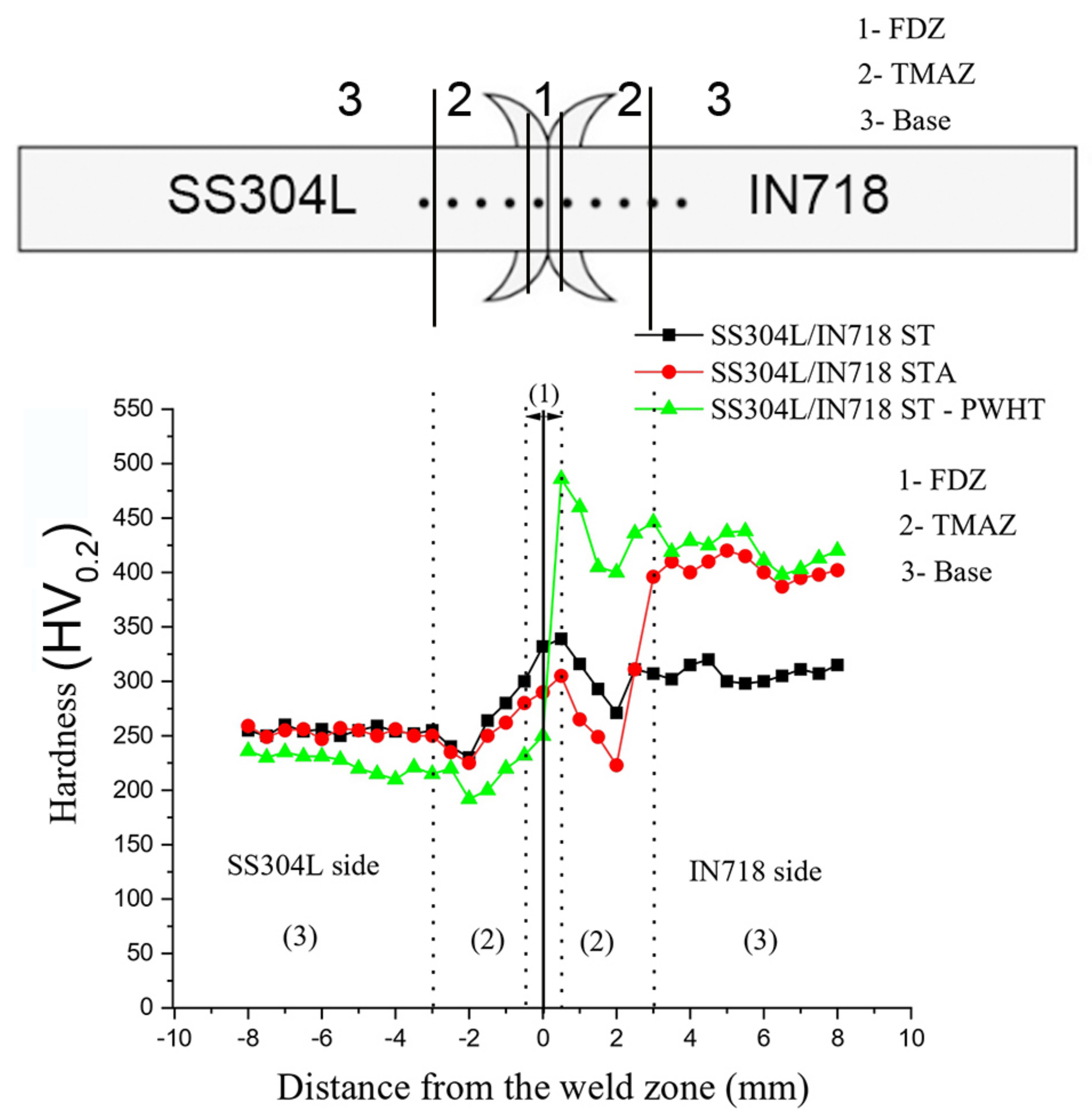
3.5.1. Microhardness

Figure 14 depicts the microhardness profile across the interface of the dissimilar SS304L/IN718 ST, STA, and PWHT friction welds. The SS304L/IN718 dissimilar friction welds in the ST condition (335 ± 4 HV) showed higher hardness values than those in the STA condition (300 ± 5 HV) in the FDZ zone on the IN718 side near the weld interface. This is because the IN718 side of the SS304L/IN718 ST weldment experienced a greater strain hardening effect compared to the SS304L/IN718 STA weldment.
It was expected that the IN718 side of the SS304L/IN718 STA would undergo a lower deformation compared to the ST condition, because of the strengthening γ″ precipitates in the IN718 STA base metal. As discussed earlier (Table 4), the FDZ of the IN718 side of the SS304L/IN718 ST weldment showed finer recrystallized grains than the SS304L/IN718 STA weldment. The finer grains in the FDZ of the SS304L/IN718 ST on the IN718 side resulted in a higher hardness. It was observed that the IN718 side FDZ of the SS304L/IN718 STA weldment showed lower weld zone hardness (300 ± 5 HV) than the corresponding base material (415 ± 5 HV) in the as-welded condition. This was due to the dissolution of the strengthening precipitates in the weld zone because of the higher peak temperatures experienced at the weld interface during the welding, while the IN718 STA base metal was in the peak hardened condition.
In contrast, the IN718 side FDZ of the SS304L/IN718 ST weldment showed higher hardness values in the weld zone (335 ± 4 HV) than the base material (305 ± 5 HV), which could be attributed to the grain refinement of the FDZ, as a result of dynamic recrystallization. Mary and Jahazy [17] reported similar findings for the microhardness profile of IN718 linear friction welds. However, in the SS304L/IN718 dissimilar joints, the weldment with the PWHT condition (486 ± 4 HV) exhibited the highest hardness compared to all three conditions (ST, STA, and PWHT) at the weld interface on the IN718 side of the weld. This increase in hardness at the weld interface on the IN718 side was attributed to the combined effects of precipitate formation by PWHT and the grain refinement. Damodaram et al. [27] reported similar observations in previous investigations involving the friction welding of IN718 alloys. The hardness values of the dissimilar friction welds in the ST condition (305 ± 10 HV) were greater than those of the welds in the STA condition (265 ± 10 HV) in the TMAZ zone on the IN718 side of the weld. This was attributed to the relative coarsening of the grains in the STA condition compared to the ST condition (Table 4) and also to the higher strain hardening effect on the SS304L/IN718 ST samples than the STA samples on the IN718 side of weldments. Damodaram et al. [3] noticed similar variations of hardness values when studying the microstructural and mechanical properties of IN718-IN718 similar friction welded joints. The dissimilar welds in the STA condition exhibited a lower hardness (265 ± 10 HV) in TMAZ than the BM (415 ± 5 HV) in the as-welded condition. This was a result of the dissolution of strengthening precipitates in the TMAZ. Rahman et al. [32] found similar hardness patterns in the TMAZ region of the IN718 side of rotary friction welded IN718 to IN600 joints. The IN718 side TMAZ of the SS304L/IN718 ST dissimilar joints showed higher hardness values (305 ± 10 HV) than the BM (305 ± 5 HV). However, the SS304L/IN718 PWHT dissimilar joints showed the maximum hardness (430 ± 30 HV) compared to the other three conditions (ST, STA, and PWHT) at the TMAZ on the IN718 side of the weld. This was owing to the grain refinement during the welding and the formation of strengthening precipitates because of the PWHT process [27]. Damodaram et al. [27] found a similar influence of PWHT on the microstructural and mechanical characteristics of a friction-welded IN718 alloy. On the IN718 side, lower hardness values in the HAZ/TMAZ zone were observed in all three conditions (ST, STA, and PWHT) because of the grain coarsening (Table 4) [33,34].
On the SS304L side, the hardness profile showed a decreasing trend from the FDZ to the HAZ in all three conditions (ST, STA, and PWHT). The FDZ hardness was higher than the TMAZ and BM for all the weldments on the SS304L side, owing to the grain refinement during welding. The hardness variation among zones, including FDZ, TMAZ, and base metal, on the SS304L side of both the SS304L/IN718 ST and SS304L/718 STA samples was identical. However, the softening of SS304L was due to the high temperatures experienced during PWHT, which resulted in a lower hardness than that of the weldments in the ST and STA conditions. In conclusion, the dissimilar SS304L/IN718 PWHT welds displayed the highest hardness (486 ± 4 HV) among all three conditions (ST, STA, and PWHT) at the weld interface on the IN718 side, whereas the HAZ on the SS304L side had the lowest hardness (193 ± 2 HV).

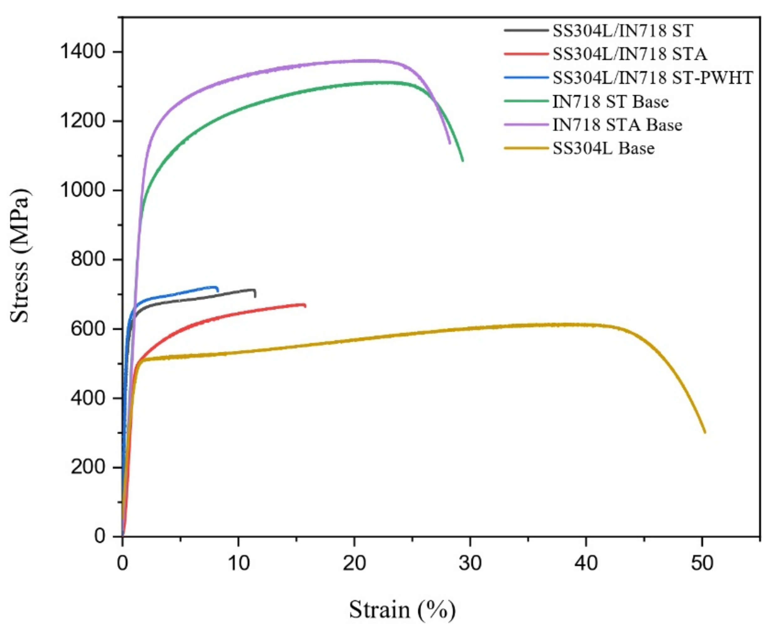
3.5.2. Tensile Properties
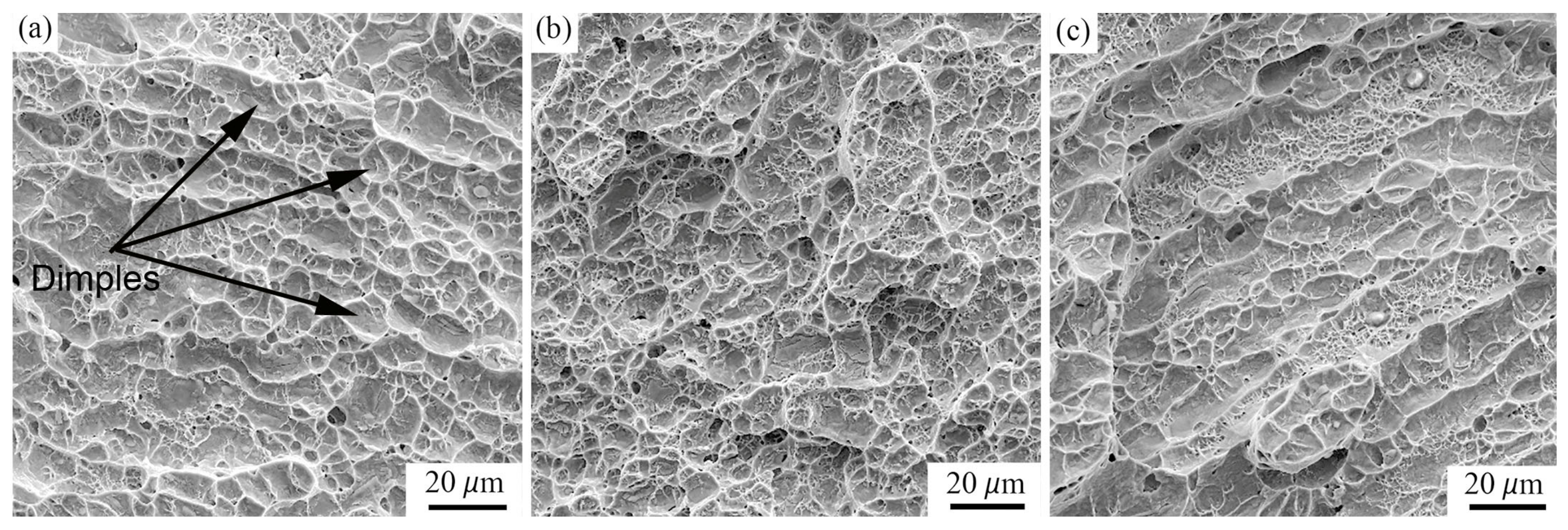
Figure 15 depicts typical room temperature tensile graphs of the three base metals and the IN718/SS304L rotary dissimilar friction welds in the ST, STA, and PWHT conditions. The SS304L/IN718 dissimilar friction welds in the STA condition exhibited lower yield strength (YS) and ultimate tensile strength (UTS) values (YS: 497 ± 2 MPa, UTS: 670 ± 3 MPa) and higher ductility values (Elongation %: 16 ± 2) when compared to welds in the ST condition (YS: 573 ± 4 MPa, UTS: 713 ± 2 MPa, Elongation %: 10 ± 1). This could have been due to the grain refinement and dissolution of strengthening precipitates at the weld zone [3]. Furthermore, when evaluating the IN718 sides of the SS304L/IN718 ST and STA weldments, the weldment in the STA condition showed a lower strain hardening effect compared to ST, due to the grain refinement at the weld interface. The SS304L/IN718 ST and STA welds had lower strength and ductility values than the IN718 base materials with prior ST and STA (ST condition: YS: 938 ± 4 MPa, UTS: 1312 ± 2 MPa, Elongation %: 30 ± 2; STA condition: YS: 1075 ± 5 MPa, UTS: 1375 ± 10 MPa, Elongation %: 28 ± 1). This was because the IN718 was rotary friction welded to the SS304L, a low-strength material. Therefore, the strength of the SS304L/IN718 dissimilar welded sample was reduced compared to the IN718 base metal under the ST and STA conditions. Rehman et al. [32] made similar findings in their investigation of the rotational friction welding of IN718 to IN600. In comparison (Table 5), the SS304L BM exhibited lower strength (YS: 460 ± 3 MPa, UTS: 615 ± 5 MPa and higher ductility (Elongation %: 51 ± 4) values. The SS304L/IN718 PWHT welds exhibited higher strength values (YS: 604 ± 5 MPa, UTS: 721 ± 4 MPa) and lower ductility values (Elongation %: 07 ± 1) in comparison to all other welds (ST, STA, PWHT) (Table 5).
This was most likely due to the fact that SS304L is not heat-treatable, and hence the PWHT only improved the strength in IN718. This increase in strength in the PWHT sample on the IN718 side was due to the formation of strengthening precipitates γ′ and γ″. Similar observations were made by Lalam et al. [35] during the friction welding of IN718 and EN24 dissimilar metal combinations. Table 5 summarizes the average YS, UTS, and % Elongation values. Figure 16 depicts the failure position of the SS304L/IN718 transverse tensile welded specimens in the ST, STA, and PWHT conditions. The SS304L/IN718 ST and SS304L/IN718 STA dissimilar welds were observed to fail near the HAZ of SS304L because of the grain coarsening in the HAZ zone. Similar results were reported by Anwar et al. [31] in rotary friction weld joints of alloy-800H. It was expected that the mechanical intermixing would result in better interfacial bonding compared to the weld interface without intermixing zone. As discussed earlier, the SS304L/IN718 ST showed prominent mechanical intermixing at the weld interface compared to the SS304L/IN718 STA sample. Moreover, the SS304L/IN718 STA also exhibited good weld joints due to the expulsion of the oxide layer and atomic diffusion as a result of the plastic deformation and higher temperatures experienced during friction welding. It is worth noting that in the present study, both samples failed in the HAZ of the SS304L side, due to the sound weld interface in both conditions.
The SS304L/IN718 PWHT welded samples were observed to fail in the base of the SS304L side, due to the grain coarsening-induced softness on the SS304L side caused by the increased temperature exposure throughout the aging process. Similar observations were made by Nam Yong Kim et al. [24] during the friction welding of Alloy 718 and SNCRW stainless steel. They reported that tensile samples without PWHT fractured at the weld joint, whereas after PWHT, the fracture occurred in the SNCRW parent metal.

3.5.3. Fractography

Figure 17a–c show SEM micrographs of the tensile fracture surfaces of dissimilar SS304L/IN718 rotary friction welds in the ST, STA, and PWHT conditions, respectively. All the samples displayed ductile fractures with dimples and microvoids. After the microvoids nucleated and grew in size, they joined together to form larger voids until the residual cross-sectional area of the tensile specimen was too small to sustain the applied stress; at that point, a ductile fracture occurred. On the other hand, the SS304L/IN718 PWHT dissimilar weld exhibited coarser dimples than the SS304L/IN718 ST and SS304L/IN718 STA dissimilar welds, which might be attributed to the failure area’s coarse grain size, notably the SS304L base region. Similar trends were observed by Anwar et al. [31] in rotary friction welded joints of Alloy-800H.

4. Conclusions

The dissimilar SS304L/IN718 welds in this investigation were prepared utilizing the rotary continuous friction welding process. The influence of heat treatment on the microstructural and mechanical properties was evaluated under ST, STA, and PWHT conditions. The following conclusions were drawn:
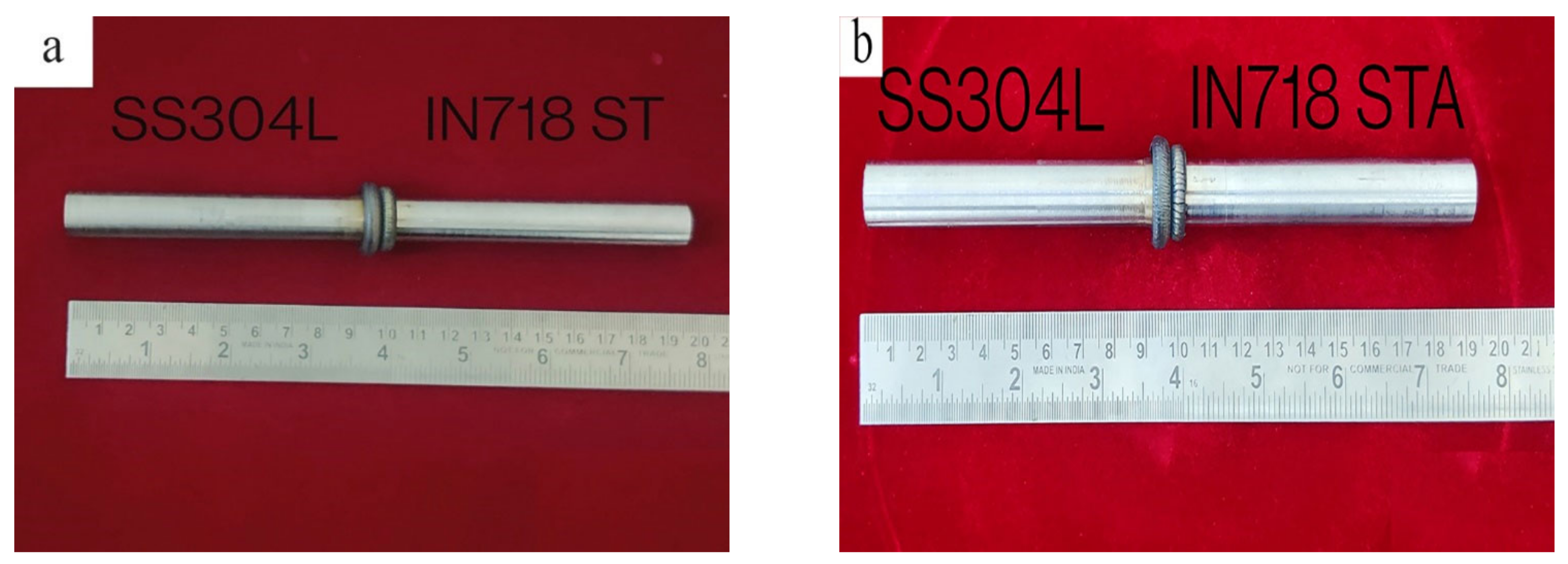
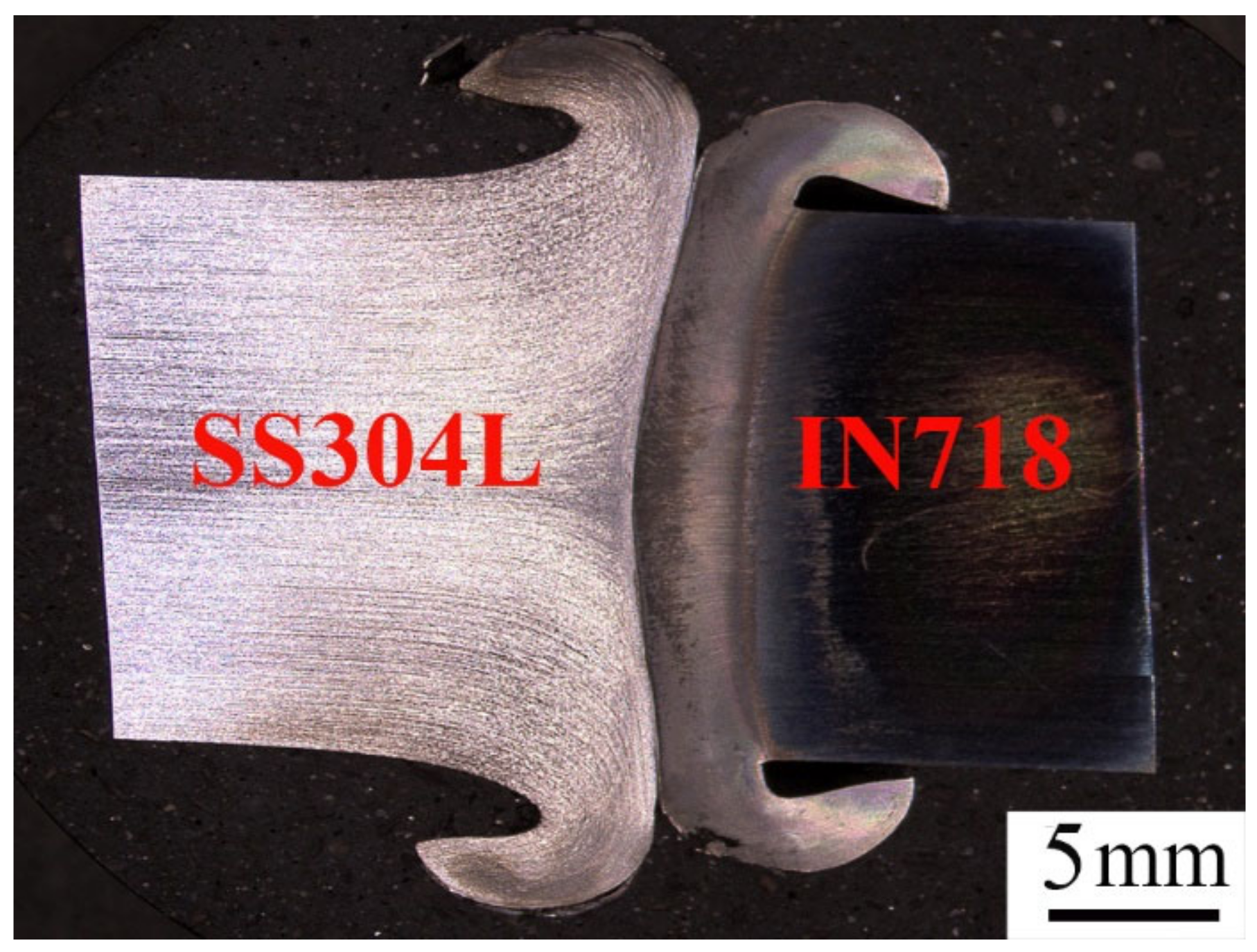
  • Defect-free dissimilar SS304L/IN718 welds with no solidification cracking, fissure cracks, or imperfect bonding could be attained using the rotary continuous friction welding process.
  • The macrostructure of dissimilar SS304L/IN718 welds revealed a higher flash on the SS304L side and less flash on the IN718 side, owing to a sharp reduction in flow stress in the SS304L at high temperatures.
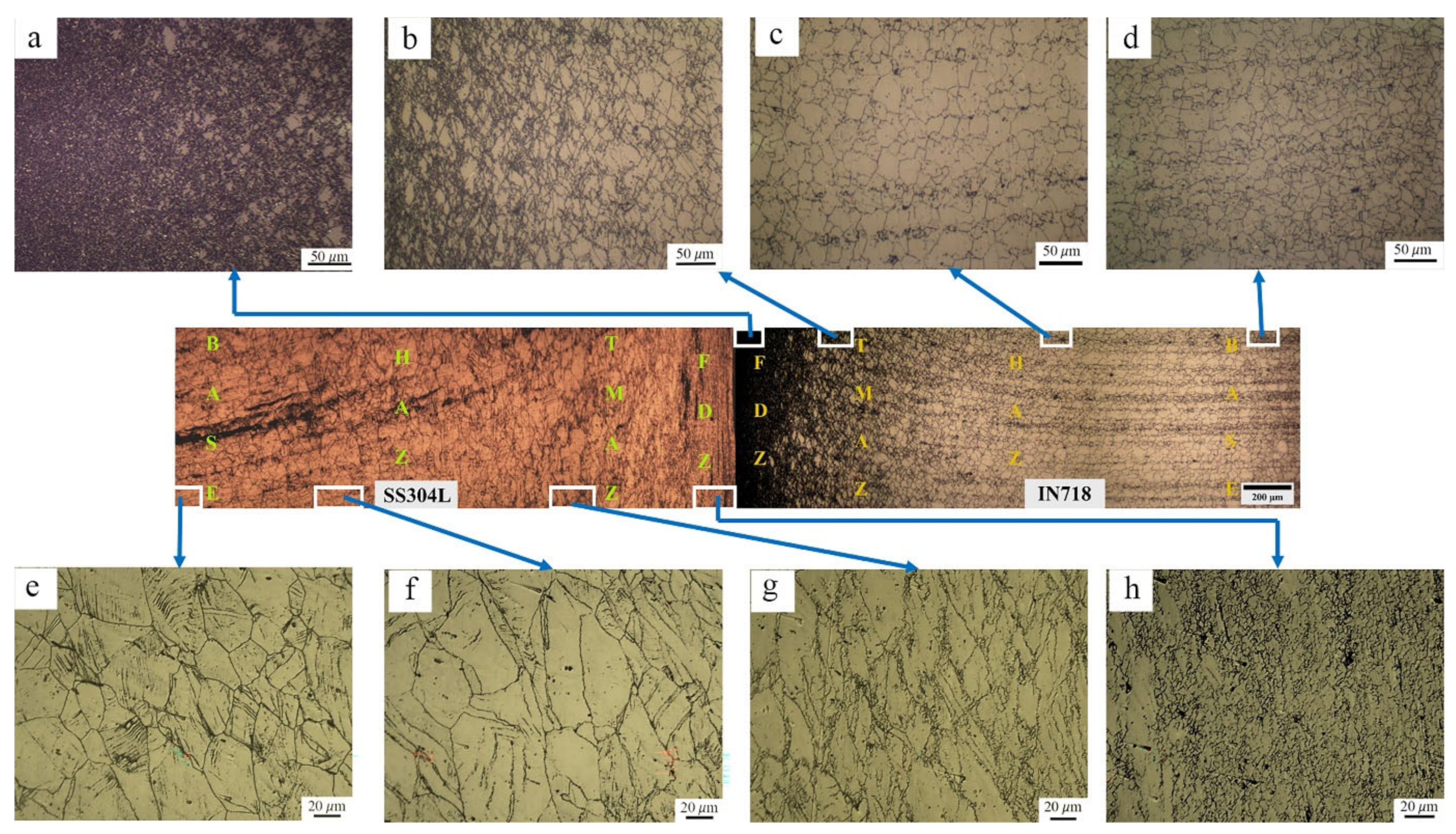
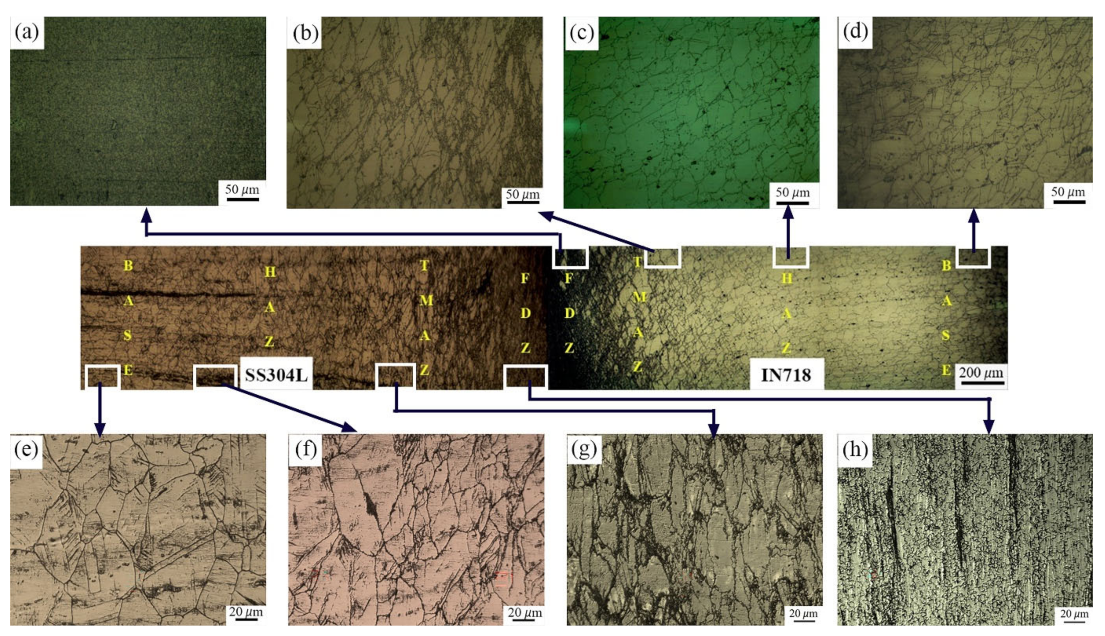
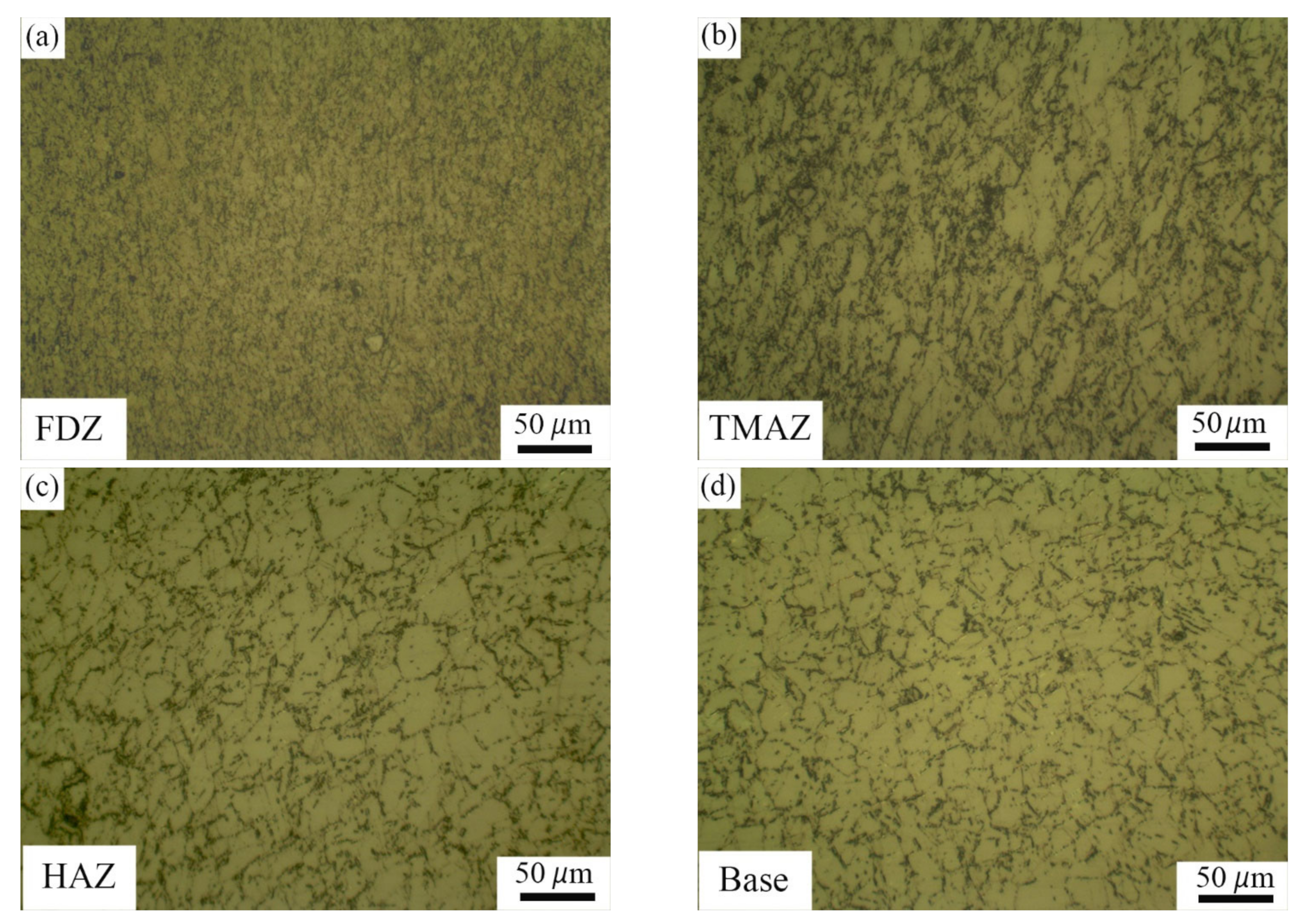
  • The dissimilar friction welds of SS304L/IN718 in the ST and STA conditions underwent dynamic recrystallization, as shown by the finer equiaxed grains in the FDZ, with an average grain size of 6 ± 2 µm. This encourages the creation of high-quality joints with superior mechanical properties.
  • The SS304L/IN718 weldment in the PWHTed condition showed the highest hardness (486 ± 4 HV) in the FDZ of IN718; this was due to the creation of strengthening precipitates. The lowest microhardness of 193 ± 2 HV was observed in the HAZ on the SS304L side of the SS304L/IN718 PWHT, due to grain coarsening.
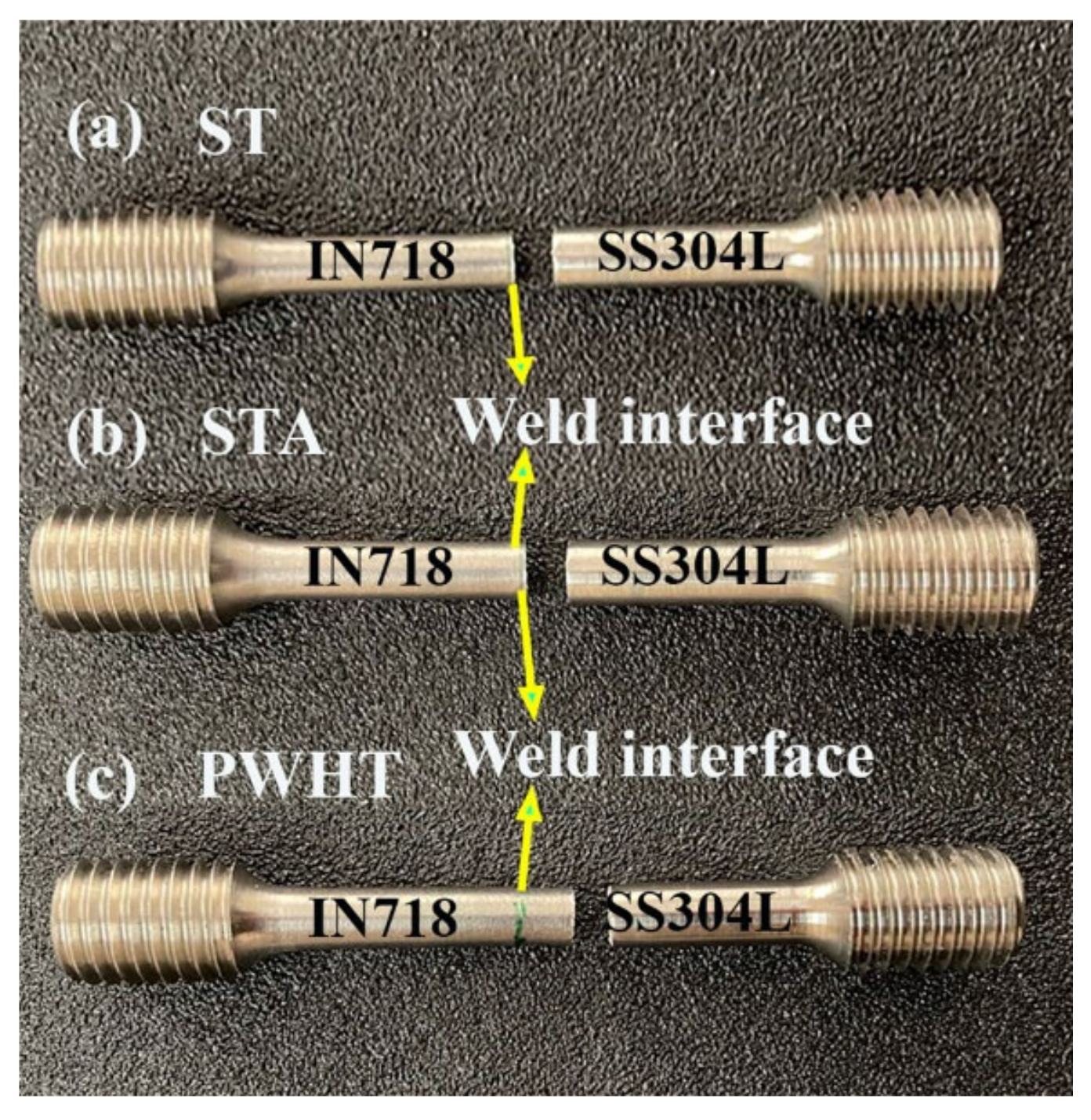
  • Among all the weldments, the dissimilar SS304L/IN718 weldment in the PWHTed condition showed a higher strength and lower elongation (UTS-721 ± 4 MPa, 7 ± 1% elongation). This could be attributed to the formation of strengthening precipitates γ′ and γ″ in IN718. Furthermore, the PWHTed weldment failed in the BM region of SS304L, while the other two welds (ST, STA) failed in the HAZ region of SS 304L.
  • To obtain the best combination of mechanical properties, while keeping the practical difficulties of welding large components in mind, a dissimilar SS304L/IN718 rotary friction welded joint should be welded in a solution-treated (ST) condition and subjected to post-weld heat treatment (PWHT).

Author Contributions

Conceptualization, P.P., M.K.T. and N.K.B.; Data curation, P.P., M.K.T. and N.K.B.; Formal analysis, P.P., M.K.T., N.K.B., A.U.R. and P.S.; Funding acquisition, A.U.R. and P.S.; Investigation, P.P., M.K.T., N.K.B. and A.U.R.; Methodology, P.P., M.K.T., N.K.B., A.U.R. and P.S.; Resources, M.K.T., N.K.B., A.U.R. and P.S.; Supervision, M.K.T., N.K.B. and A.U.R.; Visualization, P.P., M.K.T., N.K.B., A.U.R. and P.S.; Writing—original draft, P.P., M.K.T. and N.K.B.; Writing—review and editing, M.K.T., N.K.B., A.U.R. and P.S. All authors have read and agreed to the published version of the manuscript.

Funding

This research was funded by King Saud University through Researchers Supporting Project number (RSPD2023R701), King Saud University, Riyadh, Saudi Arabia.

Institutional Review Board Statement

Not applicable.

Informed Consent Statement

Not applicable.

Data Availability Statement

Data are contained within this article.

Acknowledgments

The authors are thankful to King Saud University for funding this work through Researchers Supporting Project number (RSPD2023R701), King Saud University, Riyadh, Saudi Arabia.

Conflicts of Interest

The authors declare no conflict of interest.

Abbreviations

STsolution-treated
STAsolution-treated and aged
PWHTpost-weld heat treatment
FDZfully deformed zone
TMAZthermomechanical affected zone
HAZheat affected zone
BMbase material
DRXdynamic recrystallization
ASTMAmerican Society for Testing and Materials

References

  1. Ghaderi, S.; Karimzadeh, F.; Ashrafi, A. Evaluation of microstructure and mechanical properties of transient liquid phase bonding of Inconel 718 and nano/ultrafine-grained 304L stainless steel. J. Manuf. Process. 2020, 49, 162–174. [Google Scholar] [CrossRef]
  2. Kumar, S.; Sudhakar Rao, G.; Chattopadhyay, K. Effect of surface nanostructure on tensile behavior of superalloy IN718. Mater. Des. 2014, 62, 76–82. [Google Scholar] [CrossRef]
  3. Damodaram, R.; Raman, S.G.S.; Rao, K.P. Microstructure and mechanical properties of friction welded alloy 718. Mater. Sci. Eng. A 2013, 560, 781–786. [Google Scholar] [CrossRef]
  4. Prasad, K.S.; Rao, C.S.; Rao, D.N. Study on weld quality characteristics of micro plasma arc welded austenitic stainless steels. Procedia Eng. 2014, 97, 752–757. [Google Scholar] [CrossRef] [Green Version]
  5. Anitha, P.; Majumder, M.C.; Saravanan, V.; Rajakumar, S. Microstructural Characterization and Mechanical Properties of Friction-Welded IN718 and SS410 Dissimilar Joint. Metallogr. Microstruct. Anal. 2018, 7, 277–287. [Google Scholar] [CrossRef]
  6. Reddy, G.M.; Mohandas, T.; Rao, A.S.; Satyanarayana, Y.V. Influence of welding processes on microstructure and mechanical properties of dissimilar austenitic-ferritic stainless steel welds. Mater. Manuf. Process. 2005, 20, 147–173. [Google Scholar] [CrossRef]
  7. Kong, Y.S.; Cheepu, M.; Kim, D.G. Microstructure and Mechanical Properties of Friction-Welded and Post-Heat-Treated Inconel 718. Trans. Indian Inst. Met. 2020, 73, 1449–1453. [Google Scholar] [CrossRef]
  8. Huang, X.; Chaturvedi, M.C.; Richards, N.L. Effect of homogenization heat treatment on the microstructure and heat-affected zone microfissuring in welded cast alloy 718. Metall. Mater. Trans. A Phys. Metall. Mater. Sci. 1996, 27, 785–790. [Google Scholar] [CrossRef]
  9. Anandaraj, J.A.; Rajakumar, S.; Balasubramanian, V.; Petley, V. Investigation on mechanical and metallurgical properties of rotary friction welded In718/SS410 dissimilar materials. Mater. Today Proc. 2021, 45, 962–966. [Google Scholar] [CrossRef]
  10. Cheepu, M.; Che, W.S. Characterisation of Interfacial Microstructure in Friction Welds Between Inconel 718 and SM45C Steel. Trans. Indian Inst. Met. 2020, 73, 1567–1571. [Google Scholar] [CrossRef]
  11. Wang, H.; Ikeuchi, K.; Takahashi, M.; Ikeda, A. Microstructures of Inconel 718 alloy subjected to rapid thermal and stress cycle—Joint performance and its controlling factors in friction welding of Inconel 718 alloy. Weld. Int. 2009, 23, 662–669. [Google Scholar] [CrossRef]
  12. Kirik, Í.; Özdemýr, N. Effect of process parameters on the microstructure and mechanical properties of friction-welded joints of aisi 1040/aisi 304l steels. Mater. Tehnol. 2015, 49, 825–832. [Google Scholar] [CrossRef]
  13. Özdemir, N. Investigation of the mechanical properties of friction-welded joints between AISI 304L and AISI 4340 steel as a function rotational speed. Mater Lett. 2005, 59, 2504–2509. [Google Scholar] [CrossRef]
  14. Liu, F.C.; Nelson, T.W. Grain structure evolution, grain boundary sliding and material flow resistance in friction welding of Alloy 718. Mater. Sci. Eng. A 2018, 710, 280–288. [Google Scholar] [CrossRef]
  15. Sayed, A.M.; Alanazi, H. Performance of Steel Metal Prepared Using Different Welding Cooling Methods. Case Stud. Constr. Mater. 2022, 16, e00953. [Google Scholar] [CrossRef]
  16. Humphreys, F.J.; Hatherly, M. Chapter 1—Introduction. In Recrystallization and Related Annealing Phenomena, 2nd ed.; Elsevier: Oxford, UK, 2004; pp. 1–10. [Google Scholar]
  17. Mary, C.; Jahazi, M. Linear friction welding of IN-718 process optimization and microstructure evolution. Adv. Mater. Res. 2007, 15–17, 357–362. [Google Scholar] [CrossRef]
  18. Gobu, N.; Mahadevan, K. Evaluation of Mechanical and Metallurgical Properties of Friction Welded Inconel 600 and Aisi 304L Austenitic Stainless Steel Dissimilar Joints. J. Manuf. Eng. 2016, 11, 171–177. [Google Scholar]
  19. Satyanarayana, V.V.; Reddy, G.M.; Mohandas, T. Dissimilar metal friction welding of austenitic-ferritic stainless steels. J. Mater. Process. Technol. 2005, 160, 128–137. [Google Scholar] [CrossRef]
  20. Dey, H.C.; Ashfaq, M.; Bhaduri, A.K.; Rao, K.P. Joining of titanium to 304L stainless steel by friction welding. J. Mater. Process. Technol. 2009, 209, 5862–5870. [Google Scholar] [CrossRef]
  21. Muralimohan, C.H.; Muthupandi, V.; Sivaprasad, K. Properties of Friction Welding Titanium-stainless Steel Joints with a Nickel Interlayer. Procedia Mater. Sci. 2014, 5, 1120–1129. [Google Scholar] [CrossRef] [Green Version]
  22. Guo, W.; You, G.; Yuan, G.; Zhang, X. Microstructure and mechanical properties of dissimilar inertia friction welding of 7A04 aluminum alloy to AZ31 magnesium alloy. J. Alloys Compd. 2017, 695, 3267–3277. [Google Scholar] [CrossRef]
  23. Zhu, Y.; Guo, Y.; Yang, L. Microstructure-based strength distribution across the welds of nickel-based superalloy inconel 751 and austenite steel 21-4N joined by inertia friction welding. Metall. Mater. Trans. B Process Metall. Mater. Process. Sci. 2013, 44, 396–405. [Google Scholar] [CrossRef]
  24. Kim, N.Y.; Kim, J.H.; Kong, Y.S.; Yoon, J.W.; Yeom, J.T.; Lee, D.G.; Park, N.K. The Effect of Post Weld Heat Treatment on Mechanical Properties of Friction-Welded Alloy 718 and SNCRW Stainless Steel. Adv. Mater. Res. 2007, 26–28, 511–514. [Google Scholar] [CrossRef]
  25. Maalekian, M. Friction welding—Critical assessment of literature. Sci. Technol. Weld. Join. 2007, 12, 738–759. [Google Scholar] [CrossRef]
  26. Mandal, S.; Jayalakshmi, M.; Bhaduri, A.K.; Subramanya Sarma, V. Effect of Strain Rate on the Dynamic Recrystallization Behavior in a Nitrogen-Enhanced 316L(N). Metall. Mater. Trans. A Phys. Metall. Mater. Sci. 2014, 45, 5645–5656. [Google Scholar] [CrossRef]
  27. Damodaram, R.; Ganesh Sundara Raman, S.; Prasad Rao, K. Effect of post-weld heat treatments on microstructure and mechanical properties of friction welded alloy 718 joints. Mater. Des. 2014, 53, 954–961. [Google Scholar] [CrossRef]
  28. Zhao, T.; Rong, S.; Hao, X.; Wang, Y.; Chen, C.; Wang, T. Effect of Nb-V microalloying on hot deformation characteristics and microstructures of Fe-Mn-Al-C austenitic steel. Mater. Charact. 2022, 183, 111595. [Google Scholar] [CrossRef]
  29. Huang, Z.W.; Li, H.Y.; Preuss, M.; Karadge, M.; Bowen, P.; Bray, S.; Baxter, G. Inertia friction welding dissimilar nickel-based superalloys alloy 720Li to IN718. Metall. Mater. Trans. A Phys. Metall. Mater. Sci. A 2007, 38, 1608–1620. [Google Scholar] [CrossRef]
  30. Cheepu, M.; Venkateswarlu, D.; Nageswara Rao, P.; Muthupandi, V.; Sivaprasad, K.; Che, W.S. Microstructure characterization of superalloy 718 during dissimilar rotary friction welding. Mater. Sci. Forum MSF 2019, 969, 211–217. [Google Scholar] [CrossRef]
  31. Anwar, S.; Rehman, A.U.; Usmani, Y.; Al-Samhan, A.M. Influence of post weld heat treatment on the grain size, and mechanical properties of the alloy-800h rotary friction weld joints. Materials 2021, 14, 4366. [Google Scholar] [CrossRef] [PubMed]
  32. Rehman, A.U.; Usmani, Y.; Al-Samhan, A.M.; Anwar, S. Rotary friction welding of inconel 718 to inconel 600. Metals 2021, 11, 244. [Google Scholar] [CrossRef]
  33. Anbarasan, N.; Gupta, B.K.; Prakash, S.; Muthukumar, P.; Oyyaravelu, R.; Kumar, R.J.F.; Jerome, S. Effect of Heat Treatment on the Microstructure and Mechanical Properties of Inconel 718. Mater. Today Proc. 2018, 5, 7716–7724. [Google Scholar] [CrossRef]
  34. Vincent, R. Precipitation around welds in the nickel-base superalloy, Inconel 718. Acta Metall. 1985, 33, 1205–1216. [Google Scholar] [CrossRef]
  35. Lalam, S.V.; Reddy, G.M.; Mohandas, T.; Kamaraj, M.; Murty, B.S. Continuous drive friction welding of Inconel 718 and EN24 dissimilar metal combination. Mater. Sci. Technol. 2009, 25, 851–861. [Google Scholar] [CrossRef]
Figure 1. Typical solution treatment and two-step aging cycle.
Applsci 13 03584 g001
Figure 2. Tensile test specimen geometry.
Applsci 13 03584 g002
Figure 3. (a) Optical micrograph of the SS304L base metal, (b) secondary electron micrograph of the SS304L base metal.
Applsci 13 03584 g003
Figure 4. (a) Optical micrograph of the IN718 solution-treated (ST) base metal, (b) SEM micrograph showing ծ-based precipitates, and (c) a typical EDS precipitate spectrum.
Applsci 13 03584 g004
Figure 5. (a) Optical micrograph of the IN718 solution-treated and aged (STA) base metal, (b) SEM micrograph showing ծ-based precipitates.
Applsci 13 03584 g005
Figure 6. A visual view of SS304L/IN718 friction weld joint in the as-welded (a) ST, and (b) STA conditions.
Applsci 13 03584 g006
Figure 7. The macrostructure of the dissimilar rotary friction welded SS304L/IN718 ST sample shows more flash on the SS304L side.
Applsci 13 03584 g007
Figure 8. The optical microstructure of the SS304L/IN718 rotary friction welds in the as-welded, solution-treated condition (SS304L/IN718 ST). IN718 side: (a) FDZ (b) TMAZ (c) HAZ (d) base metal; SS304L side: (e) base metal (f) HAZ (g) TMAZ (h) FDZ.
Applsci 13 03584 g008
Figure 9. The optical microstructure of the SS304L/IN718 rotary friction welds in the as-welded, solution-treated, and aged conditions (SS304L/IN718 STA). IN718 side: (a) FDZ (b) TMAZ (c) HAZ (d) base metal; SS304L side: (e) base metal (f) HAZ (g) TMAZ (h) FDZ.
Applsci 13 03584 g009
Figure 10. SEM micrograph of the SS304L/IN718 ST weldment at the interface region.
Applsci 13 03584 g010
Figure 11. SEM micrograph of the SS304L/IN718 STA weldment at the interface region.
Applsci 13 03584 g011
Figure 12. Scanning electron microscopy image in the secondary electron mode (a) inter-mixed Region (b) SS304L/IN718 in the as-welded ST condition and (c) the corresponding energy dispersive spectroscopy (EDS) line scan.
Applsci 13 03584 g012
Figure 13. Cross-sectional optical micrographs of dissimilar SS304L/IN718 friction welds in the PWHT condition: (a) FDZ, (b) TMAZ, (c) HAZ, and (d) BM regions.
Applsci 13 03584 g013
Figure 14. Hardness distribution across the weld interface of dissimilar SS304L/IN718 rotary friction welded joints in the as-welded ST, STA, and PWHT conditions.
Applsci 13 03584 g014
Figure 15. The typical tensile properties of the base metals and dissimilar SS304L/IN718 rotary friction welds in the as-welded ST, STA, and PWHT conditions.
Applsci 13 03584 g015
Figure 16. The failure location of the dissimilar SS304L/IN718 joints in the (a) as-welded ST, (b) as-welded STA, and (c) PWHT conditions.
Applsci 13 03584 g016
Figure 17. Fracture surfaces of the dissimilar SS304L/IN718 welded joints in the (a) as-welded ST, (b) STA, and (c) PWHT conditions.
Applsci 13 03584 g017
Table 1. Base material compositions of Inconel718 and SS304L.
MaterialNiCrFeNbMoAlTiVMnSiCBP
IN71851.618.219.75.13.20.51.10.30.090.350.0040.0030.015
SS304L8.21871.5-0.23---2.000.750.024-0.045
Table 2. Optimum welding parameters used to fabricate the joint.
ParametersValues
Rotation speed1800 rpm
Soft force28 MPa
Soft force time0.5 s
Friction force195 MPa
Friction burn off4 mm
Upset force390 MPa
Upset time4 s
Table 3. Etchant details.
MaterialEtchant (Electrolytic Etching)
IN71810 g of oxalic acid + 90 mL deionized water (3 volts DC) (15–20 s)
SS304L60 mL of HNO3 + 40 mL of distilled water (2 volts DC) (15–20 s)
Table 4. Average grain sizes of the various zones in friction welded SS304L/IN71.
ConditionSS304LIN718
ZonesFDZTMAZHAZBMFDZTMAZHAZBM
ST12 ± 3 µm27 ± 9 µm36 ± 9 µm30 ± 9 µm6 ± 2 µm14 ± 6 µm25 ± 5 µm19 ± 3 µm
STA10 ± 3 µm27 ± 9 µm37 ± 9 µm31 ± 8 µm8 ± 1 µm19 ± 4 µm28 ± 7 µm24 ± 5 µm
PWHT14 ± 4 µm29 ± 7 µm38 ± 9 µm31 ± 10 µm11 ± 2 µm24 ± 5 µm29 ± 6 µm27 ± 12 µm
Table 5. Typical tensile data of the base metals and welded joints.
SampleYield Strength
(MPa)
Ultimate Strength (MPa)Elongation
(%)
Location of Failure
IN718 ST Base938 ± 41312 ± 230 ± 2-
IN718 STA Base1075 ± 51375 ± 1028 ± 1-
SS304L Base460 ± 3615 ± 551 ± 4-
IN718 ST-SS304L573 ± 4713 ± 210 ± 1Near weld interface on SS304L side
IN718 STA-SS304L497 ± 2670 ± 316 ± 2Near weld interface on SS304L side
IN718-SS304L PWHT604 ± 5721 ± 407 ± 1SS304L base
Disclaimer/Publisher’s Note: The statements, opinions and data contained in all publications are solely those of the individual author(s) and contributor(s) and not of MDPI and/or the editor(s). MDPI and/or the editor(s) disclaim responsibility for any injury to people or property resulting from any ideas, methods, instructions or products referred to in the content.

