Abstract
The current work is devoted to the numerical determination of the wind speed value, which can cause the overturning of the mobile elevating work platform of the scissor lift type. In the first step of the analysis, the scaled model of the real vehicle is prepared. In the second step, the model is used in the aerodynamic tunnel to determine the aerodynamic force values and moment, which act on the vehicle. The three different configurations of the work platform are considered, namely: (a) The work platform raised to the maximum height with an additional bridge extended, (b) the work platform raised to the maximum height, and (c) the work platform half raised. In each position, the direction of the wind is changed from the range from 0° to 180° with an increment equal to 15°. In the next step of the analysis, the CFD simulations are carried out. The ANSYS Fluent R22 software is used. As a model of turbulent airflow, the standard k-ε with standard wall function is adopted. The obtained experimental results are used to verify the numerical model. A very good agreement between the results of the experiment and the results of numerical simulations is obtained. As the main result of the numerical study, the values of the tipping moment and corresponding wind speed that cause the overturning of the analyzed real scissor lift are determined. It occurred that the lowest value of the wind speed is obtained for the first variant of the vehicle configuration V1crt = 22.315 m/s for the angle of the wind speed direction β = 30° and the highest one for the third variant V3crt = 34.534 m/s and β = 15°, without any persons on the work platform. The presence of human beings on the work platform is also considered.
1. Introduction
Among the different kinds of mobile elevating work platforms (MEWP), the scissor lift seems to be very useful and effective in practical usage. However, as in the case of other devices of this kind, the workers are exposed to various hazards. As is reported in the available literature [1], according to the Census of Fatal Occupational Injuries, a Bureau of Labor Statistics database, in 1992–1999 the number of deaths of construction workers because of different accidents was equal to 339 of which 19% were different accidents with the use of scissor lifts. According to another source [2], namely, Census of Fatal Occupational Injuries, 306 fatalities between 1992 and 2003 were caused by the usage of the different kinds of aerial lifts, and 78 of these fatalities specifically involved scissor lifts. The causes of these accidents can be quite different [3], but it seems that the most dangerous is the tip-over of the whole mobile platform [4]. The overturning can be caused by the wind load [5,6]. According to media information, the issue of scissor lifts accidents and safety is described in [7,8,9,10,11].
It should be stressed here that according to the different standards (European Standard, Eurocode 1–4 [12], British Standard, BS 2573-1 [13], American Society of Civil Engineers, ASCE 7-16 [14], Japanese standard [15] or Chinese standard, GB/T 3811-2008 [16]), the load caused by the wind is treated as static load where the impact of the adjacent structures is omitted. In the case of the mobile elevating work platforms (MEWP), including scissor lifts, the appropriate design rules are defined in the standard EN 280-1:2022 [17].
However, such a simple approach can be inadequate in comparison with the wind load phenomenon, especially in the case of large-scale engineering structures like gantry cranes, tower cranes, or MEWP of a different kind. Therefore, the important aspect of the analysis of the wind load is the measurement of the wind load in the case of real structures [18,19,20]. Based on these results, the appropriate wind conditions can be imitated in the aerodynamic tunnels, where the scaled models of the real large-scale structures can be tested in order to determine the wind load (forces and moments coefficients) [21,22,23]. Together with the rapid development of computers and software, it is also possible to carry out numerical simulations of the airflow around crane-like structures [24,25,26]. Moreover, having the distribution of the static pressure (caused by wind) on the surface of the studied structure, it is possible to carry out further mechanical analysis based on the fluid-solid interaction [27].
Here, it should be noted that the papers which are devoted to the impact of the wind load on the scissor lifts are rather rare, thus the below brief survey of the literature also contains works, which consider the actions of the wind on other types of crane-like devices. However, the standard approach is to prepare the scaled model of the real large-scale structure for experimental tests in the aerodynamic tunnel. The obtained results are used to validate the numerical model [28].
It is worth noting that the wind load, especially the gust of wind, which is very often two times greater in comparison with the mean wind speed and a frequency of about 1 Hz [19], can also cause the vibration of structures. Chen and Li [29] studied the displacement of a lattice tower. The results of the nonlinear dynamic analysis show that the displacement obtained from the time-history analysis is higher by about 5–28% in comparison with the static one. Next, Takahashi et al. [30] studied the runaway of quayside container cranes subjected to transient gusty winds. They also proposed the sliding state while approaching the runaway and after a runaway caused by a wind gust. Chen et al. [31] studied the interference effect of the different segments of a tower crane subjected to wind load. The wind coefficients of a full-scale model of a tower crane were calculated by CFD, and then the time history of wind loads, simulated through the autoregressive method, was applied to the finite element model of a tower crane. Although the maximum wind load direction of the tower crane was perpendicular to its jib, the obtained results reveal that the maximum along-wind load direction was deflected 30°–60°, and the mean ratio of the absolute value of the across-wind coefficient to the along-wind coefficient of the tower crane was about 8.56%. Su et al. [32] studied the effect of stochastic dynamic transient gusty winds on the sliding and overturning of quayside container cranes. The main conclusion is that dynamic transient gusty wind-induced peak response follows type III (Weibull) extreme value distribution. Azzi et al. [33] performed wind tunnel tests on an aeroelastic lattice tower model. The obtained results reveal the resonance contribution could reach a maximum of 18% of the peak response of the tower.
In 2022, several interesting works were published, which concern the problem of the impact of the wind load on crane-like structures. Lu et al. [34] took into consideration the problem of the outer-attached tower cranes installed on super high-rise buildings and exposed to wind-induced vibration. The numerical CFD simulations and structural FEM calculations were performed. He et al. [35] presented a study, which concerns a similar problem. To avoid sophisticated finite element analysis of the main building, a modified generalized flexural-shear model (FSM-MS) was proposed to estimate the along-wind and across-wind displacement response of the main building and the response at the connection support of the tower crane. Yeon et al. [36] studied the lift effect on wind load estimation for a semi-submersible rig. Wind loads on the analyzed rig were calculated under the maritime atmospheric boundary layer. The obtained results match well with those from the wind tunnel within a ±20% error.
The influence of the lifted load on the stability of crane-like devices has also been investigated. Here, two exemplary works can be quoted, namely Monteiro et al. [37] and Cekus et al. [38].
At the end of this brief survey of the literature, it is also worth mentioning the wind-induced interference effect (IE). The analysis of this problem provides insights into how the neighborhood’s other structures influence the studied structure by changing the surface pressure caused by the wind. However, the cases of crane-like devices are rarely found. Here, the work by Wu et al. [39] can be mentioned. The author of this work investigated the wind load and wind-induced dynamic response of three quayside container cranes. Other similar works concerning lattice structures refer to the mutual influence of a system of antennas, for example, Holmes et al. [40], Carril et al. [41], and Martín et al. [42]. The interference factor of microwave antenna dishes is found to be greater than one for some wind directions. The interferon effect has also been investigated for tall buildings [43], low-rise buildings [44,45,46,47], cooling towers [48,49], and scaffoldings [50].
This work should be treated as a continuation of the previous one [51]. The current work is devoted to the problem of determining the wind speed, which causes the tip-over of the scissor lift in the case when there are no workers on the platform and in the case when there are one, two, or more persons on the platform. The main aim of this effort is to increase the safety of the workers when the device is in service. Basically, the value of the moment induced by the wind, which causes a tip-over of the studied scissor lift, is determined based on the results obtained from the CFD simulation. However, the used numerical model is verified by the experimental tests performed in the aerodynamic tunnel, namely, the values of aerodynamic forces obtained from simulations and experiments are compared. Taking into consideration the geometrical dimensions of the real device, the scaled model of the scissor lift is made. Having verified the numerical model, the critical wind speed value can be determined for a real-scale scissor lift. Moreover, knowing the value of the mean aerodynamic force, which acts on the human being, the impact of the presence of the workers on the platform can also be estimated on the critical wind speed.
2. Materials and Methods
2.1. Object of Investigation
As it was mentioned above, the object of the current analysis, shown in Figure 1, is the scissor lift MEC 4191RT [52]. Table 1 presents the technical data and geometric dimensions of the actual structure.
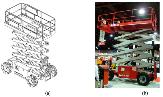
Figure 1.
The scissor lift MEC 4191RT: (a) isometric projection [52]; (b) real object of investigation [53].

Table 1.
Selected technical data and geometrical dimensions of the scissor lift MEC 4191RT [52].
The MEC 4191RT mobile platform is adapted to work in difficult terrain. All four wheels are driven and steerable, equipped with off-road tires. The source of the traction drive is a liquid-cooled diesel engine with a power (Liquid-cooled, Kubota DF752 Dual Fuel or Kubota D1105 Diesel engine) of 8.7 kW. The scissor mechanism is built of two parallel, interconnected scissor kinematic systems, each of which consists of five members. The basic element of the scissor system consists of two double-armed levers (rectangular steel profiles) with arms of identical length connected in the middle with a pin. The members being kinematic pairs relate to each other by the ends of the two-arm levers and by means of pins.
The unfolding and folding of the scissor mechanism are carried out by means of two hydraulic cylinders, one of which is attached to the first pair and the other to the last pair. At the same time, both hydraulic cylinders are coupled to the middle pair. The entire scissor mechanism is connected to the chassis frame at the bottom and to the platform frame at the top. One arm of the lever is connected to the slider moving along the guides, and the other is connected to the frame through a pivot enabling rotation.
The working platform is made of metal. The floor of the working deck is made of special steel mesh, the balustrade is made of rectangular steel profiles. The platform has a manually extended side platform, which increases its surface by about 1/3.
2.2. Experimental Setup
For experimental research in the aerodynamic tunnel, the model of the investigated scissor lift with an approximate scale of 1:14 is prepared. Due to the specificity of the research, it is important to maintain the geometric dimensions of the model in relation to the real object, while some elements were simplified or omitted. Simplifications used in the model: (a) Arms of the scissor mechanism made of full profiles (originally an open rectangular profile), (b) connections of the scissor mechanism members made with the use of screws and bushings (originally pins), (c) stabilizing supports permanently integrated with the chassis (in the original it is possible to disassemble), (d) rigidly mounted road wheels, (e) elements of the platform and covers of the engine and hydraulic system made of 3 mm thick PVC.
Making the scissor mechanism from full profiles and the use of PVC with a thickness inconsistent with the scale of the model is reasonable because the overall dimensions have been preserved, and thus the reference surface, which is needed to determine the force and moment coefficients. Moreover, the whole described simplifications of the scaled model do not affect the surface in the orthogonal projection. The scaled model with the geometrical dimensions is shown in Figure 2.
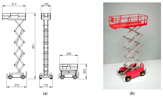
Figure 2.
The model of the scissor lift (approximate scale 1:14): (a) The general geometrical dimension of the model, (b) the model in isometric projection.
The experimental tests are carried out for three configurations of the scissor lift, namely:
- configuration 1, where the work platform of the model is positioned 891 mm from the floor level (height measured to the top guardrail, as is shown in Figure 2 with extended roll-out deck),
- configuration 2, the configuration of the scissor lifts the same as in the case of variant 1, but the roll-out deck is retracted, and finally,
- configuration 3, where the work platform is positioned 450 mm from the tunnel floor level to the top guardrail with retracted roll-out deck.
In all mentioned cases, it is assumed that the wind direction varies from 0° to 180° with an increment equal to 15°. At this stage of analysis, the presence of workers on the platform is not considered. The impact of the presence of people will be studied further.
The assumed coordinate system and the way the angle of wind direction is defined are shown in Figure 3. For the tested model of the scissor lift, the aerodynamic moment Mz and aerodynamic forces Fx and Fy are measured using the three-component aerodynamic balance based on the electric resistance strain gauges [54]. The orientation of the fixed coordinate system x, y, z is as follows: x—along wind direction, y—across wind direction, z—vertical direction.
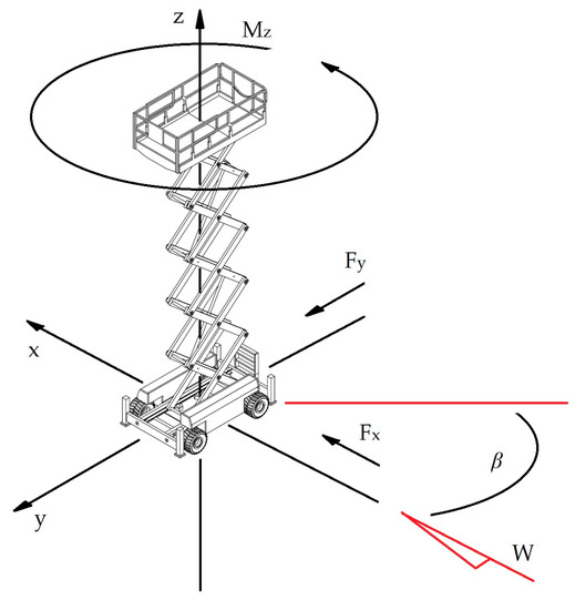
Figure 3.
The orientation of the model in the coordinate system x, y, z; and the aerodynamic test conditions: The assumed wind direction W; the angle of diverting the wind β; the aerodynamic moment Mz and aerodynamic forces Fx and Fy.
The sensitivity of the aerodynamic balance in the range of 0 to 2 N in increments of 0.1 N is 89.4%, in the range of 2 to 10 N in increments of 2 N is 92.9%, and in the range of 10 to 50 N in increments of 10 N is 99.7% [54]. A similar topic, including research in a wind tunnel, was described in [55,56,57].
2.3. Aerodynamic Tunnel
The experimental tests were carried out in the boundary layer wind tunnel at the Wind Engineering Laboratory at the Cracow University of Technology [58]. The wind tunnel, with a length of 10 m and a measurement area of 2.2 × 1.4 m, allows for conducting tests in both closed and open circuits. The wind flow was generated by an axial fan with a diameter of 2.7 m and an efficiency of 0.8–0.9, and a blade tip speed of about 100 m/s. The fan was driven by a 200-kW alternating current motor with a nominal speed of 750 rpm, controlled by an inverter. The maximum wind speed was approximately 40 m/s (144 km/h). Figure 4 and Figure 5 show the wind tunnel and CFD simulation with the study models in the 1st and 3rd configurations for the selected angle of wind attack. Figure 4a shows the mast, where the two wind speed sensors are installed: One of them 0.5 m and the second 0.92 m above the tunnel floor. The intensity of the turbulence was controlled by a system of spires about 0.8 m high and 0.3 m wide (Figure 4).
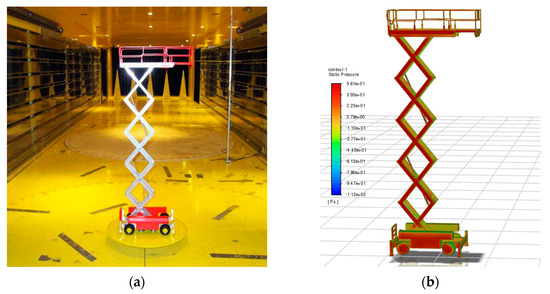
Figure 4.
Model of the scissor lift at maximum working height with extended roll-out deck (conf. 1): (a) During the aerodynamic tests, (b) the CFD simulation.
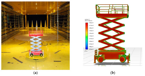
Figure 5.
Model of the scissor lift at medium working height (conf. 3): (a) During the aerodynamic tests, (b) the CFD simulation.
2.4. Measurement of the Force Components Acting on the Model and Corresponding Wind Speed
The schema of the applied measuring system is presented in Figure 6. The model of the scissor lifts 1 was installed on the aerodynamic balance 2. A, B—special segments with strain gauges. It is the device that enables the determination of components Fx and Fy of the aerodynamic forces as well as the moment Mz with respect to the coordinate system shown in Figure 3. The aerodynamic balance relates to the electronic system 3 controlling the stepper motor of the turntable and with the strain gauge bridge 4 measuring the aerodynamic forces. The wind speed was evaluated via two thermo-anemometer probes 5 and 6, which were connected to the thermo-anemometer ANT 2000 7. Aerodynamic forces and wind speed measurements were recorded via a PCI 1710 card 8 on a PC 9.
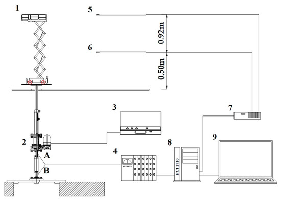
Figure 6.
The schema of the measuring system (1—the scissor lift, 2—the aerodynamic balance, 3—the electronic system, 4—the stepper motor, 5 and 6—the thermo-anemometer probes, 7—the thermo-anemometer, 8—PCI 1710 card, 9-PC, and A, B—the segments with strain gauges).
The sampling time of the wind speed is equal to 5000 ms. The exemplary graph of the wind speed variations measured via sensors 5 and 6 is presented in Figure 7. Here, it should be noted that the average value of the wind speed measured by sensor 6 is about 15% lower in comparison with the value indicated by sensor 5. Moreover, based on the graph in Figure 7, the average intensity of turbulence Iv can also be evaluated according to the following formula:
where σv is the standard deviation of the measuring wind speed and Vref is the reference speed, which is equal:
where pref is the reference pressure. The standard deviation can be computed based on the dynamic component vdyn(t) of the instantaneous velocity V(t), where V(t) = Vref + vdyn(t).
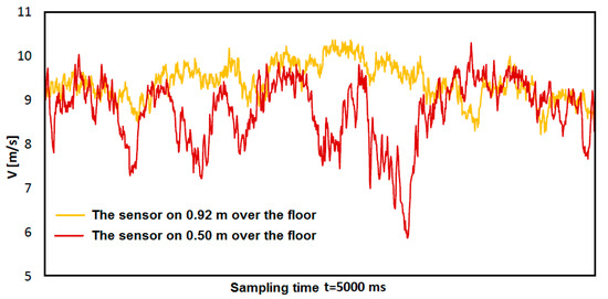
Figure 7.
Wind speed measured with two anemometers placed at different heights.
The wind speed, which was measured at the point localized 500 mm over the floor of the aerodynamic tunnel, was generally lower in comparison with the wind speed measured at 920 mm over the floor. It was caused by the set of “spires”, which were installed at the beginning of the tunnel in order to induce the initial turbulence. The spires were much wider at the basis in comparison with their summits. Therefore, the wind speed was much more disturbed at the level of 500 mm and, in consequence, the average wind speed was lower.
The formulas determining the coefficient of aerodynamic drag Cx, the coefficient of the lateral aerodynamic force Cy, the aerodynamic coefficient of torque CMz, and the aerodynamic coefficient of the moment, which caused the tip-over MC are as follows:
where: Fx—aerodynamic drag N, Fy—lateral force respectively N, V—the average wind speed m/s, ρ—the mass air density, Aref—effective area of one of the supporting structures of the model, i.e., the area of the shadow normal projected by its members on a plane parallel to the wall equal 0.051 m2, rref—the reference dimension adopted by convention, the width of the structure of the model equal 0.116 m and href is half of the total height of the model equal to 0.446 m.
2.5. CFD Simulations
The airflow simulations were carried out with the use of the Fluent software in the ANSYS Workbench R22 environment (Figure 8). The main aim of these simulations was to determine the aerodynamic forces and moments acting on the studied scissor lift, more specifically, force, and moment coefficients. These quantities were defined by Equation (3).
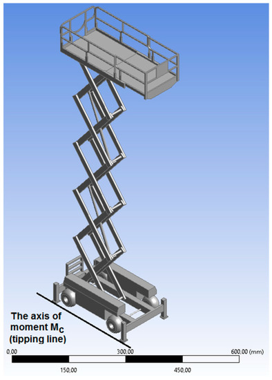
Figure 8.
The CAD model of the studied scissor lift created with the use ANSYS Design Modeler R22.
In the performed simulations, we assumed standard air properties, therefore, ρ = 1.225 kg/m3, T = 15 °C, p0 = 101,325.25 Pa. Moreover, the model of the scissor lift was immersed in a rectangular space filled with air with external dimensions 2.2 × 1.4 m and a length of 2 m, which corresponded to the dimensions of the wind tunnel. The tunnel walls were modeled as stationary boundaries.
One of the most important problems was the appropriate choice of the turbulent model. In the current work, we considered three most frequently applied in practice models, namely: Reynolds stress model, model k-ω, and model k-ε. The first mentioned model, used by Wu et al. [39], caused the computations to converge unacceptably slowly. The second model, used by He et al. [35], Yeon et al. [36], and Monteiro et al. [37], requires preparing the specific mesh at the boundary conditions. For estimation made for the studied structure, the first layer of the finite volume should be about 7 × 10⁻⁵ m in height. Unfortunately, it leads to an enormous number of nodes and finite element volumes.
Finally, the standard k-ε model with a standard wall function has been used. It is worth noting that this model is still in use, for example, the works of Zan et al. [26], Chen et al. [31], Lu et al. [34]. The application of this model caused the computations are converging relatively quickly. Obtaining the solution demands less than 100 iterations.
3. Results
To validate the numerical model, the obtained computation values of Cx and Cy are compared with those, which are determined as the results of experimental tests (Table 2, Table 3 and Table 4).
Table 2.
Experimental results obtained for configuration 1.
Table 3.
Experimental results obtained for configuration 2.
Table 4.
Experimental results obtained for configuration 3.
3.1. Results of the Experimental Tests
Table 2, Table 3 and Table 4 show the collected results of the experimental tests, which are obtained in the case of configurations 1st, 2nd, and 3rd, respectively. In the 5th column, the average wind speed is computed based on indications obtained from sensors 5 and 6. As can be observed, the highest values of the Fx component of the aerodynamic force are obtained for angle β equal to 30° and 150° for all configurations. The highest values of the Fy component are for the angle β from the range of 45° to 60° and, respectively, 120° to 135°. The average turbulence computed for all cases is equal to Iv = 6.32%. The average wind speed is equal to 8.355, 8.322, 7.945 m/s, for configurations 1st, 2nd, and 3rd, respectively.
3.2. Results of the Numerical Simulations
The values of the forces and moments induced by the wind, which act on the investigated scissor lift, are estimated based on the distribution of the static pressure. Mentioned distribution is obtained from CFD simulation. The exemplary distribution of the static pressure is depicted in Figure 9.
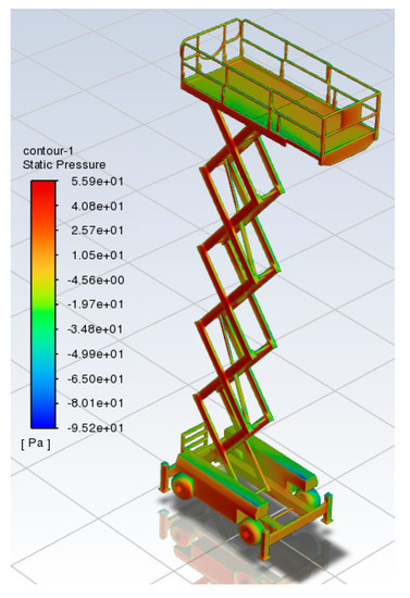
Figure 9.
The exemplary distribution of the static pressure (β = 30°).
The impact on the values of the forces and moment coefficients are analyzed for different sizes of the volume cells. Table 5 shows the values of the force and moment coefficients, which are obtained for different approximate cell sizes. The finite volume mesh creates the cells of the tetrahedron shape of variable edge length. It is assumed that on the surface of the studied structure, the length of the cell edge is about 1.5, 2.0, …, 3 mm while the length of the edge cells on the channel walls, inlet, and outlet boundaries is equal to about 70 mm. The computations are performed for variant 1, where it is assumed turbulence intensity IV = 6.32%, the hydraulic diameter DH = 1.712 m, wind speed V = 7.872 [m/s], and angle β = 30°.
Table 5.
The force and moment coefficients for different finite volume mesh.
As can be observed, the obtained numerical solution shows a good global convergence, thus, for further computations, we assumed the following mesh sizes: 1.5 mm on the surface of the scissor lift and 70 mm on the rest of the external boundaries.
The influence of the turbulence intensity on the force and moment values and moment coefficients is also investigated. As is reported in Table 2, Table 3 and Table 4, the estimated value of the turbulence intensity varies in the range from 4% to 10%. The computations are performed for the initial parameters the same as in the previous convergence analysis and for the finally assumed mesh sizes. The obtained results are shown in Table 6. As can be observed, together with the increase in the turbulent intensity, the values of the analyzed coefficients also increase slightly. Therefore, it seems that the choice of the turbulent intensity equal to IV = 6.32% seems to be reasonable.
Table 6.
The force and moment coefficients for different turbulent intensity.
3.3. Comparison of the Experimental and Numerical Results
As can be observed in Figure 10, Figure 11 and Figure 12, the comparison of the results obtained from experimental tests and numerical simulations reveals a very good agreement. In the case of the Cx force coefficients, the average error is defined as follows:
where , are the force coefficients obtained from the experiment and numerical computations, respectively. For variant 1 the average error is equal to ε1AVG = 8.177%, and for variants 2 and 3 is equal to ε2AVG = 8.982% and ε3AVG = 8.055%. It seems that the results of the numerical simulation slightly overestimate the value of the aerodynamic force Fx, which plays an important role when the tip-over of the scissor lift could happen. Moreover, the best match is obtained for configuration 3 of the investigated device. Finally, it is worth noting that in the case of the force coefficient Cy, the results from experimental tests and numerical simulations seem to be an even better match than in the case of Cx force coefficients.
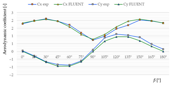
Figure 10.
Comparison of the force coefficient Cx and Cy for the experimental and numerical results as function of angle of wind attack β in the case of configuration 1.
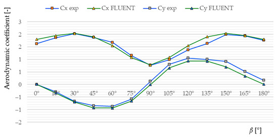
Figure 11.
Comparison of the force coefficient Cx and Cy for the experimental and numerical results as function of angle of wind attack β in the case of configuration 2.
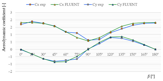
Figure 12.
Comparison of the force coefficient Cx and Cy for the experimental and numerical results as function of angle of wind attack β at the case of configuration 3.
4. Discussion
4.1. Calculation of Overturning and Stabilizing Moments
The maximum overturning MO and corresponding stabilizing moments MS shall be calculated for the most unfavorable tipping lines. In this case, tipping line is between supports of the scissor lift. For solid and foam-filled tires, according to ISO 4305, the tipping lines determined may be taken at 1/4 of the tire ground contact width from the outside of the ground contact width.
The calculations are made with the scissor lift in the most unfavorable extended (configuration 1) with the maximum allowable inclination of the chassis equal to 0.5°, as shown in Figure 11. We assume that the scissor lift used out-of-doors is being affected by wind at a pressure of 100 N/m2, equivalent to a wind speed of 12.5 m/s (Beaufort Scale 6) according to EN 280-1:2022. All loads and forces which can act simultaneously are considered in their most unfavorable combinations according to the graphical method for on-slope stationary example presented in Figure 13.
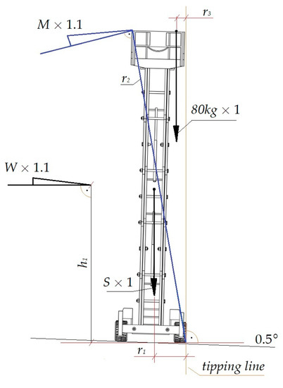
Figure 13.
The schema of the load acting on real object scissor lift for level ground stationary example according to [17].
The platform is stable when the condition is met:
where: MS is the sum stabilizing moments, MO is the sum overturning moments. The stabilizing moments, according to the standard EN 280-1:2022 (and level ground stationary), include:
MS1—is the moment resulting from the product of the structural load S = 43,164 N acting on the arm r1 equal to 1.1 m from the tipping line. S—vertical direction. The self-weight and all technical data of a real object are shown in Table 3. The masses of the components of the scissor lift are taken to be static structural loads (not moving), Table 7—factor equal to 1.
Table 7.
The load and force directions for stability calculations for scissor lift [17].
MS2 = 181.29 Nm—is the moment resulting from the product of the person load equal to 784.8 N acting on the arm r3 equal to 0.231 m.
To the overturning moments include:
MO1 = 7497.73 Nm—is the moment resulting from the product of the wind loads W = 956.65 N acting on the arm h1 equal to 7.125 m, W—horizontal direction. If the scissor lift is being affected by wind at a pressure of 100 N/m2, equivalent to a wind speed of 12.5 m/s that the wind load acting on the scissor lift at the full area of the real object is A = 9.996 m2 is equal to W = 956.65 N. Wind forces are assumed to act horizontally at the center of the area of the parts of the scissor lift and persons and equipment on the work platform h1. Wind load W is taken to be dynamic forces with factor 1.1 (Table 7).
MO2 = 5593.28 N—is the moment resulting from the product of the manual force—dynamic M = 400 N acting on the arm r2 equal to 12.71 m. The minimum value for the manual force M is taken as 400 N for the scissor lift designed to carry more than one person (Table 1), applied at the height of 1.1 m above the work platform floor. The manual force—dynamic M is taken to be dynamic forces with factor 1.1 (Table 7).
Taking the above data into account, condition (5) is as follows:
and conclude that the condition for the stability of the scissor lift is satisfied.
4.2. Calculation of Overturning and Stabilizing Moments with Used to Aerodynamic Coefficients Obtained from Experiment and CFD
The obtained values of aerodynamic coefficients from the experiment and from the CFD simulation are used to determine forces FX, and FY acting relative to the tipping line of the scissor lift of the real object of investigation.
Next, we determined the reduced value of force Frd and moment Mrd acting relative to the tipping line of the scissor lift as a function of the angle of wind attack β.
The moment Mrd is taken to be dynamic moment with factor 1.1.
Finally, the sum overturning moments from experiment MOexp and CFD simulation MO CFD due to wind direction was determined:
and the comparison of the results for three different wind speeds acting on the scissor lift is shown in Figure 14, Figure 15 and Figure 16.
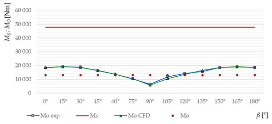
Figure 14.
Comparison of the overturning and stabilizing moments received from the experimental and numerical tests with the calculation based on [17] for the wind speed V = 12.5 m/s (config. 1).
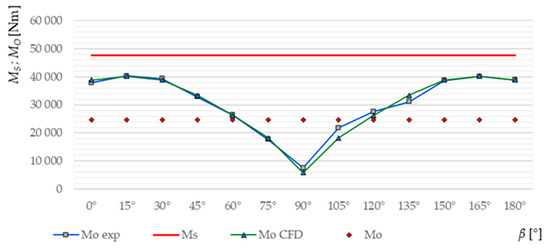
Figure 15.
Comparison of the overturning and stabilizing moments received from the experimental and numerical tests with the calculation based on [17] for the wind speed V = 20 m/s (config. 1).
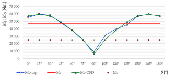
Figure 16.
Comparison of the overturning and stabilizing moments received from the experimental and numerical tests with the calculation based on [17] for the wind speed V = 25 m/s (config. 1).
Taking the above discussed results into account, the characteristics of the overturning moment as a function of wind speed for the angle of 15° can be determined (Figure 17).
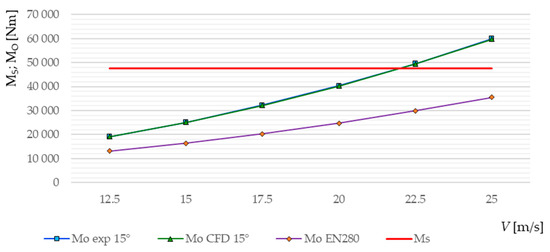
Figure 17.
Comparison of the overturning and stabilizing moments received from the experimental and numerical tests for 15° angle of wind attack with the calculation based on standard EN280 for the wind speed V = 12.5–25 m/s.
According to Figure 17, the scissor lift will be overturned at approximately 21.95 m/s (76.825 km/h). Note, however, that according to the standard and manufacturer’s data, the maximum wind speed is 12.5 m/s (45 km/h).
4.3. Calculation of Overturning and Stabilizing Moments with Used to Aerodynamic Coefficients Obtained CFD
Figure 18a shows the values of the moment coefficients CMc, which could cause the overturning of the investigated scissor lift as a function of the wind direction described by angle β together with the assumed schema of the acting loads.
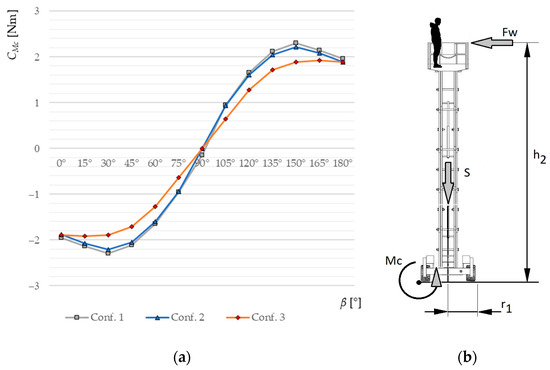
Figure 18.
Calculation based on the CFD (a) the moment coefficient CMc as a function of the wind direction described by angle β, (b) the schema of the loads acting on the investigated scissor lift.
As can be observed, the most dangerous situation is when the wind blows along the direction, which creates the angle β = 30° with the X-axis of the coordinate system shown in Figure 3 for configurations 1st and 2nd. In the case of configuration 3rd, the most dangerous wind direction is equal to β = 15°. It is worth noting that the extended movable deck has no significant impact on the moment M induced by the wind. The maximal values of the coefficients are as follows C1Mc = 2.299, C2Mc = 2.212, and C3Mc = 1.920 for configurations 1st, 2nd, and 3rd, respectively.
To estimate the wind speed, which could cause the tip over the investigated scissor lift, it is assumed that MS < MC, where MS is the static moment generated by the self-weight of the structure, Figure 18b. This moment can be computed as follows:
where S = 44 kN is the self-weight of the scissor lift (Table 1) and r1 = 2.31 m, according to the technical properties of the scissor lift presented in Table 1. Next, assuming the density of the air is equal to ρ = 1.225 kg/m3, the critical wind speed can be determined as:
where Aref = 9.996 m2 and href = 7.25 m for the configuration 1st, 2nd and href = 3.625 m for the configuration 3rd for the real structure. Finally, the critical values of the wind speed for studied variants of the scissor lift are as follows: V1crt = 22.315 m/s (80.337 km/h), V2crt = 22.750 m/s (81.902 km/h), and V3crt = 34.534 m/s (124,322 km/h). The obtained values seem to be relatively high, but the main impact on the critical values of the wind speed possess the presence of the workers on the platform.
The estimation of the impact of the presence of human beings on the work platform on the critical wind speed should be considered quite problematic. First, the people who stand on the platform of the scissor lift are not “permanently installed” on the floor. Therefore, they can transfer the load induced by wind only when they lean on the guardrails. Moreover, the highest load induced by the silhouette of a man is when the people are positioned facing the wind direction. Besides, people differ from each other in height, silhouette, and weight. Thus, there are an almost infinite number of possibilities. Therefore, it seems that the most reasonable approach to estimating the impact of the presence of people on the work platform of the scissor lifts on the critical wind speed is to involve the superposition principles. In the available literature, one can find papers where the authors try to determine the drag force acting on the human body induced by wind, for example, Gjeta et al. [59], Koo et al. [60], Thomas [61], or Hunt et al. [62].
The authors of the first-mentioned work [59] performed several CFD simulations to estimate the drag force induced by the human body. Calculations are made for a person of medium build, 172 cm tall. The results of their simulations are reprinted in Table 8.
Table 8.
The values of the drag force acting on the human body according to [59].
To estimate the impact of the presence of workers on the platform on the value of the critical wind speed, in the first step, the moment MC1 induced by the wind at the speed of V0 = 20 m/s acting on the scissor lift is computed. The assumed density of the air is equal to ρ = 1.225 kg/m3. Next, the moment MW generated by a single worker of the approximate weight GW = 800 N is evaluated, namely MW = FW h2, where FW is the drag force, whose value can be found in Table 8 for the wind speed V0 (frontal position), and the h1 = 12.5 m is the distance between the ground and the top guardrail level for configuration 1st, 2nd and h1 = 7.25 m for configuration 3rd. Finally, the total moment MC induced by the wind blowing with a speed equal to V0 can be computed with the use of the following formula:
where nw is the number of workers on the platform. According to [51], the reference area of the human body is equal to about 0.555 m2. Therefore, it can be neglected. Now, the coefficient CT of the total moment MT induced by the wind can be computed again according to Equation (3). The presence of the people on the platform also increases the total weight of the structure:
Finally, the values of the critical wind speed causing the tip-over of the investigated scissor lift with the various number of workers on the platform can be determined with the use of Equation (6). Table 9 presents the appropriate values of the critical wind speed for studied variants of scissor lift configurations as a function of the number of workers.
Table 9.
The critical value of the wind speed VCRT [m/s].
In the case of configurations 1st and 2nd, the presence of a single worker does not reduce the critical wind speed dramatically. However, the maximal number of persons on the platform causes the value of the critical wind speed to be lower in comparison with the value for the empty platform, about 7 m/s (2 km/h). In the case of configuration 3rd, the reduction of the value of the critical wind speed is the greatest, about 18 m/s (6 km/h).
5. Conclusions
The current work concerns the problem of the critical wind speed determination, which can cause the tip-over of the scissor lift. The analysis is performed for the device MEC 4191RT. The estimation of the critical value of the wind speed is based on results obtained from the CFD analysis of the scaled model (assumed approximate scale of the model 1:14) of the scissor lift. The computations are performed with the use of ANSYS Fluent R22. Three different configurations of the scissor list at analyzed, namely: (a) The work platform raised to the maximum height with an additional bridge extended, (b) the work platform raised to the maximum height, and (c) the work platform half raised. The numerical model is verified by the experimental test in the wind tunnel. To verify the CFD results, the values of the Fx and Fy components of the aerodynamic forces are compared, which are obtained from numerical simulations and experimental tests. A relatively good agreement is observed. In the case of the force coefficient Cx, the value of the average error does not exceed 9% for all investigated configurations. It is established that the most dangerous wind direction is the one that makes an angle of 30° with the X-axis of the global coordinate system, Figure 3, for all studied configurations of the scissor lift. The lowest critical wind speed is obtained for configuration 1st and is equal to V1CRT = 22.315 m/s. For other configurations, the critical wind speed is higher and equal to V2CRT = 22.75 m/s, and V3CRT = 33.534 m/s, respectively. The impact of the workers on the platform of the scissor lift on the critical wind speed is estimated based on the values of the drag force of the human body, which are available in the literature. The presence of the workers decreases the critical wind speed and, in the case, when the four persons are on the platform, the critical wind speed is equal to V1CRT = 21.513 m/s, V2CRT = 21.874 m/s, and V3CRT = 32.459 m/s for the configurations 1st, 2nd, and 3rd, respectively. The obtained results are in good agreement with these, which are obtained based on code EN 280-1:2022.
The maximum wind speed that the standard and the manufacturer specify of 12.5 m/s gives a large safety margin, as shown in Figure 14. In this case, the capsizing moment values obtained from experimental and CFD studies do not differ significantly from the values calculated from the standard (the graph is flattened). The standard gives moment values regardless of wind direction. However, it should be borne in mind that the wind during a sudden change in weather very quickly increases in strength and the terrain and buildings cause turbulence or gust conditions. Currently, every summer in our climatic conditions, there are weather anomalies, where the determination of the wind speed is impossible, much less the direction from which it will hit this supporting structure, which is the scissor lift. It is worth referring to charts in Figure 14, Figure 15 and Figure 16, which describe for which ranges of wind angle of attack the highest values of capsizing moment occur. The proposed system is unable to determine the timing of the speed increase from 12.5 m/s to higher speeds, such as 21.95 m/s. This is the speed that, for an angle of 15°, can add a corresponding moment to the sum of overturning moments, causing a loss of stability in the structure. The time given by the manufacturer that the operator needs to lower the platform from the maximum height is 50 s. The open question is if a structure of this type (operating outdoors in the open air) should not be equipped with a system for continuous measurement of wind speed and wind direction.
In the future, it is planned to study the dynamic response of this structure to strong gusts of wind. Moreover, it will take into consideration the so-called interference effect, which is connected with the existence of other objects (buildings, other crane devices, trees, etc.) which are localized close to the investigated device.
Author Contributions
Conceptualization, M.A.; methodology, M.A. and M.B.; software, M.B.; validation, M.A. and M.B.; numerical analysis, M.B.; experimental investigation, M.A.; data curation, M.A. and M.B.; writing—original draft preparation, M.A., M.B., M.C. and A.S.; writing—review and editing, M.A., M.B., M.C. and A.S.; visualization, M.A. and M.B. All authors have read and agreed to the published version of the manuscript.
Funding
This research received no external funding.
Institutional Review Board Statement
Not applicable.
Informed Consent Statement
Not applicable.
Data Availability Statement
Not applicable.
Conflicts of Interest
The authors declare no conflict of interest.
References
- McCann, M. Deaths in construction related to personnel lifts, 1992–1999. J. Saf. Res. 2003, 34, 507–514. [Google Scholar] [CrossRef]
- Harris, J.R.; Powers, J.R., Jr.; Pan, C.S.; Boehler, B. Fall arrest characteristics of a scissor lift. J. Saf. Res. 2010, 41, 213–220. [Google Scholar] [CrossRef] [PubMed]
- Pan, C.S.; Chiou, S.S.; Kau, T.-Y.; Wimer, B.M.; Ning, X.; Keane, P. Evaluation of postural sway and impact forces during ingress and egress of scissor lifts at elevations. Appl. Ergon. 2017, 65, 152–162. [Google Scholar] [CrossRef] [PubMed]
- Dong, R.G.; Pan, C.S.; Hartsell, J.J.; Welcome, D.E.; Lutz, T.; Brumfield, A.; Harris, J.R.; Wu, J.Z.; Wimer, B.; Mucino, V.; et al. An Investigation on the Dynamic Stability of Scissor Lift. Open J. Saf. Sci. Technol. 2012, 2, 8–15. [Google Scholar] [CrossRef]
- SEAA Helps us Get a National Perspective of Our Industry. This Knowledge is Power. Available online: https://www.seaa.net/industry-safety-info/wind-hazards-on-mobile-elevated-work-platforms (accessed on 13 January 2023).
- Jack, K.E.; Essien, U.A.; Bamisaye, O.S.; Paul, K.O.; Ozoemela, E.E.; Okpo, C.N. Enhancement of Mobile Scissor Lifting System for Windy Environments. Niger. J. Technol. 2021, 40, 229–240. [Google Scholar] [CrossRef]
- Wind Causes Scissor Lift Fall. Available online: https://vertikal.net/en/news/story/13990/wind-causes-scissor-lift-fall (accessed on 18 January 2012).
- The Influence of Wind on Lifting Activities. Available online: https://haulotte-community.haulotte.com/a/the-influence-of-wind-on-lifting-activities (accessed on 16 April 2021).
- Notre Dame’s Fatal Scissor Lift Accident Shakes Collegiate Sports Video Community. Available online: https://www.athleticbusiness.com/operations/media-technology/article/15142464/notre-dames-fatal-scissor-lift-accident-shakes-collegiate-sports-video-community (accessed on 21 November 2010).
- How Wind Rating Requirements Impact Scissor Lift Design and Safe Use. Available online: https://weatherbuild.co/2020/06/15/how-wind-rating-requirements-impact-scissor-lift-design-and-safe-use (accessed on 7 May 2020).
- Scissor Lift Fatality. Available online: https://vertikal.net/en/news/story/40067/scissor-lift-fatality (accessed on 1 July 2022).
- ISO 4032:2016; Cranes-Wind Load Assessment. ISO Copyright Office: Geneva, Switzerland, 2016.
- BS 2573-1; British Standard. Rules for the Design of Cranes Part 1: Specifications for Classification, Stress Calculations, and Design Criteria for Structures (4th Revision). BSI: San Jose, CA, USA, 1983.
- ASCE. Minimum Design Loads and Associated Criteria for Buildings and Other Structures; ASCE 7: Reston, VA, USA, 2016. [Google Scholar]
- JIS B 8830-2001; Cranes-Wind Assessment. Japanese Industrial Standards Committee: Tokyo, Japan, 2001.
- GB/T 3811-2008; Design Rules for Cranes. General Administration of Quality Supervision. Inspection and Quarantine of the People’s Republic of China: Beijing, China, 2008.
- EN 280-1:2022; Mobile Elevating Work Platforms, Design Calculations, Stability Criteria, Construction, Safety, Examinations and tests. European Standards (EN): Pilsen, Czech Republic, 2022.
- König, G.; Zilch, K.; Lappas, G. Wind loading of shipyard gantry cranes—Full scale measurements. J. Wind. Eng. Ind. Aerod. 1979, 4, 429–435. [Google Scholar] [CrossRef]
- König, G.; Zilch, K.; Lappas, G. Wind loading of shipyard gantry cranes—A comparison of full-scale measurement, wind tunnel test and gust factor approach, Wind Engineering. In Proceedings of the Fifth International Conference, Fort Collins, CO, USA, 8–13 July 1979; Volume 2, pp. 911–923. [Google Scholar]
- Farrugia, R.N.; Sant, T. Modelling wind speeds for cup anemometers mounted on opposite sides of a lattice tower: A case study. J. Wind Eng. Ind. Aerodyn. 2013, 115, 173–183. [Google Scholar] [CrossRef]
- Voisin, D.; Grillaud, G.; Solliec, C.; Beley-Sayettat, A.; Berlaud, J.-L.; Miton, A. Wind tunnel test method to study out-of-service tower crane behavior in storm winds. J. Wind Eng. Ind. Aerod. 2004, 92, 687–697. [Google Scholar] [CrossRef]
- Lee, S.-J.; Kang, J.-H. Wind load on a container crane located in atmospheric boundary layers. J. Wind Eng. Ind. Aerod. 2008, 96, 193–208. [Google Scholar] [CrossRef]
- Han, D.-S.; Han, G.-J. Force Coefficient at Each Support Point of a Container Crane According to the Wind Direction. Int. J. Precis. Eng. Man. 2011, 12, 1059–1064. [Google Scholar] [CrossRef]
- Hu, J.B.; Chen, D.; Ding, S.Q.; Qing, G.W. Simulation of the Wind Field of Gantry Cranes Based on FLUENT. Appl. Mech. Mater. 2012, 217–219, 1530–1534. [Google Scholar] [CrossRef]
- Wang, Y.-P.; Cheng, W.-M.; Du, R.; Wang, S.-B.; Yang, X.-Z.; Zhai, S.-C. Simulation analysis of wind load response for large gantry crane. Chin. J. Eng. Des. 2020, 27, 2. [Google Scholar]
- Zan, Y.F.; Guo, R.N.; Bai, X.; Ma, Y.; Yuan, L.H.; Huasng, F.X. Wind and current loads on a pipelaying crane vessel. IOP Conf. Ser. Earth Environ. Sci. 2020, 612, 012059. [Google Scholar] [CrossRef]
- ANSYS, Inc. Fluent (Version R22), Canonsburg, PA, USA. Available online: https://www.ansys.com/products (accessed on 17 January 2023).
- An, T.-W.; Lee, S.-W.; Han, D.-S.; Han, G.-J. A Study on the comparison of wind pressure on the member of container crane using wind tunnel test and CFD. In Proceedings of the Korean Institute of Navigation and Port Research Conference; Korean Institute of Navigation and Port Research: Busan, Korea, 2006; Volume 1, pp. 321–325. [Google Scholar]
- Chen, L.; Li, L. Investigation on dynamic response of steel tower structure under time-history wind load. Appl. Mech. Mater. 2012, 166, 699–707. [Google Scholar] [CrossRef]
- Takahashi, K.; Abe, M.; Fujino, T. Runaway characteristics of gantry cranes for container handling by wind gust. Mech. Eng. J. 2016, 3, 15-00679. [Google Scholar] [CrossRef]
- Chen, W.; Qin, X.R.; Yang, Z.; Zhan, P. Wind-induced tower crane vibration and safety evaluation. J. Low Freq. Noise Vib. Act. Control. 2020, 39, 297–312. [Google Scholar] [CrossRef]
- Su, N.; Peng, S.T.; Hong, N.N. Stochastic dynamic transient gusty wind effect on the sliding and overturning of quayside container cranes. Struct. Infrastruct. E 2021, 17, 1271–1283. [Google Scholar] [CrossRef]
- Azzi, Z.; Elawady, A.; Irwin, P.; Chow, A.G.; Shdid, C.A. Aeroelastic modeling to study the wind-induced response of a self-supported lattice tower. Eng. Struct. 2021, 245, 112885. [Google Scholar] [CrossRef]
- Lu, Y.; Gao, M.; Liang, T.; He, Z.; Feng, F.; Pan, F. Wind-induced vibration assessment of tower cranes attached to high-rise buildings under construction. Automat. Constr. 2022, 135, 104132. [Google Scholar] [CrossRef]
- He, Z.; Gao, M.; Liang, T.; Lu, Y.; Lai, X.; Pan, F. Tornado-affected safety assessment of tower cranes outer-attached to super high-rise buildings in construction. J. Build. Eng. 2022, 51, 104320. [Google Scholar] [CrossRef]
- Yeon, S.M.; Kwon, C.S.; Kim, Y.C.; Kim, K.S. Study of the lift effect on wind load estimation for a semi-submersible rig using the maritime atmospheric boundary layer model. Int. J. Nav. Arch. Ocean 2022, 14, 100419. [Google Scholar] [CrossRef]
- Monteiro, F.A.; Moreira, R.M. A CFD Analysis of Wind Effects on Lifted Loads. Int. J. Adv. Eng. Res. Sci. 2019, 6, 365–371. [Google Scholar] [CrossRef]
- Cekus, D.; Kwiatoń, P.; Geisler, T. The dynamic analysis of load motion during the interaction of wind pressure. Meccanica 2021, 56, 785–796. [Google Scholar] [CrossRef]
- Wu, X.; Sun, Y.; Wu, Y.; Su, N.; Peng, S. The Interference Effects of Wind Load and Wind-Induced Dynamic Response of Quayside Container Cranes. Appl. Sci. 2022, 12, 10969. [Google Scholar] [CrossRef]
- Holmes, J.D.; Banks, R.W.; Roberts, G. Drag and aerodynamic interference on Microwave dish antennas and their supporting towers. J. Wind. Eng. Ind. Aerod. 1993, 50, 263–270. [Google Scholar] [CrossRef]
- Carril, C.F., Jr.; Isyumov, N.; Brasil, R.M.L.R.F. Experimental study of the wind forces on rectangular latticed communication towers with antennas. J. Wind. Eng. Ind. Aerod. 2003, 91, 1007–1022. [Google Scholar] [CrossRef]
- Martín, P.; Elena, V.; Loredo-Souz, A.M.; Camaño, E.B. Experimental study of the effects of dish antennas on the wind loading of telecommunication towers. J. Wind. Eng. Ind. Aerod. 2016, 149, 40–47. [Google Scholar] [CrossRef]
- Kareem, A.; Kijewski, T.; Lu, P.C. Investigation of interference effects for a group of finite cylinders. J. Wind. Eng. Ind. Aerod. 1998, 77–78, 503–520. [Google Scholar] [CrossRef]
- Holmes, J.D. Wind pressure on tropical housing. J. Wind. Eng. Ind. Aerod. 1994, 53, 105–123. [Google Scholar] [CrossRef]
- Li, G.; Gan, S.; Li, Y.X.; Wang, L. Wind-induced interference effects on low-rise buildings with gable roof. J. Wind. Eng. Ind. Aerod. 2017, 170, 94–106. [Google Scholar] [CrossRef]
- Quan, Y.; Gu, M.; Yukio, T.; Huang, P. Aerodynamic interference of wind loads on roofs of low-rise buildings. J. Tongji Univ. Nat. Sci. 2009, 37, 1576–1580. [Google Scholar]
- Pindado, S.; Meseguer, J.; Franchini, S. Influence of an upstream building on the wind-induced mean suction on the flat roof of a low-rise building. J. Wind. Eng. Ind. Aerod. 2011, 99, 889–893. [Google Scholar] [CrossRef]
- Li, G.; Cao, W.B. Structural analysis and optimization of large cooling tower subjected to wind loads based on the iteration of pressure. Struct. Eng. Mech. 2013, 46, 735–753. [Google Scholar] [CrossRef]
- Ke, S.T.; Wang, H.; Ge, Y.J. Interference effect and the working mechanism of wind loads in super-large cooling towers under typical four-tower arrangements. J. Wind. Eng. Ind. Aerod. 2017, 170, 197–213. [Google Scholar] [CrossRef]
- Feng, W.; Tamura, Y.; Yoshida, A. Interference effects of a neighboring building on wind loads on scaffolding. J. Wind. Eng. Ind. Aerod. 2014, 125, 1–12. [Google Scholar]
- Augustyn, M. Wind Action on a Mobile Elevating Work Platform (MEWP) in Operational Conditions. Adv. Mater. Res. 2014, 1030–1032, 1375–1378. [Google Scholar] [CrossRef]
- MEC 4191RT Manual. Available online: https://www.mecawp.com/wp-content/uploads/2020/06/91495.pdf (accessed on 31 January 2023).
- CanLift Equipment Ltd. MEC 4191RT Scissor Lift. Available online: https://www.canlift.ca/wp-content/uploads/2019/05/mec-4191-rt.jpg (accessed on 31 January 2023).
- Ryś, J.; Augustyn, M. Innovative construction of 3-component aerodynamic balance. Adv. Mater. Mach. Design.-Key Eng. Mat. 2013, 542, 171–177. [Google Scholar] [CrossRef]
- Flaga, A.; Kłaput, R.; Augustyn, M. Wind tunnel tests of two free-standing lighting protection masts in different arrangements with surroundings roof objects and roof conditions. Eng. Struct. 2016, 124, 539–548. [Google Scholar] [CrossRef]
- Augustyn, M. Propelling torque of the self-adjusting vertical-axis rotor. IOP Conf. Ser. Mater. Sci. Eng. 2020, 744, 012009. [Google Scholar] [CrossRef]
- Augustyn, M. A vertical-axis rotor as the adjusting system of a horizontal axis wind turbine. Technol. Trans. 2020, 117, 1–14. [Google Scholar] [CrossRef] [PubMed]
- Wind Engineering Laboratory. Available online: http://www.windlab.pl/en/ (accessed on 20 February 2023).
- Gjeta, A.; Malka, L.; Hasanaj, A.; Alcani, M. The wind gusts effects on human body based on CFD simulations. In Proceedings of the V International Scientific Conference Industry, Winter Session, Borovets, Bulgaria, 9–12 December 2020; pp. 217–221. [Google Scholar]
- Koo, M.H.; Al-Obaidi, A.S.M. Calculation of Aerodynamic Drag of Human Being in Various Positions. In Proceedings of the 1st Engineering Undergraduate Research Catalyst Conference, Kuala Lumpur, Malaysia, 2013; Department of Mechanical Engineering, Taylor’s University: Subang Jaya, Malaysia, 2013; pp. 99–100. [Google Scholar]
- Schmitt, T.J. Wind-Tunnel Investigation of Air Loads on Human Beings; Report; Navy Department: Washington, DC, USA, 1954.
- Hunt, J.C.R.; Poulton, E.C.; Mumford, J.C. The effects of wind on people; New criteria based on wind tunnel experiments. Build. Environ. 1976, 11, 15–28. [Google Scholar] [CrossRef]


Disclaimer/Publisher’s Note: The statements, opinions and data contained in all publications are solely those of the individual author(s) and contributor(s) and not of MDPI and/or the editor(s). MDPI and/or the editor(s) disclaim responsibility for any injury to people or property resulting from any ideas, methods, instructions or products referred to in the content. |
© 2023 by the authors. Licensee MDPI, Basel, Switzerland. This article is an open access article distributed under the terms and conditions of the Creative Commons Attribution (CC BY) license (https://creativecommons.org/licenses/by/4.0/).