Abstract
Composite fuel is a promising energy source that allows for solving the problems of waste disposal with energy generation. Such fuel is the most accessible fuel and is cheap in comparison with fossil fuels widely used in industrial thermal power engineering. This paper presents the results of experimental studies on the effect of the initial temperature and the addition of combustible liquids and solid components on the ignition characteristics of composite fuel single droplets. Composite liquid fuels were prepared using the main components: bituminous coal, coal processing waste (filter cake), rapeseed oil, turbine oil, and water. The research was carried out for fuel droplets with an initial temperature from −60 to +60 and an ambient temperature from 700 to 1000 °C. The differences in the ignition delay times at conditions close to the limiting ones were 2–3.5 times. A promising direction for intensifying the processes of the ignition and combustion of composite liquid fuels under relatively intense heating is self-grinding into a large number of small fragments up to complete disintegration due to the dispersion effect. It has been experimentally found that the addition of highly flammable liquids (gasoline, kerosene, diesel fuel, formic acid) to the fuel composition in an amount of 5% is characterized by an intensification of ignition and burnout of droplets by about two times. The ignition delay time is reduced by 20–40%, while the size of the dispersion area is increased by 20–70%. The addition of formic acid to the composite fuel has a positive effect on the main ignition characteristics from 5 to 50%, and the addition of a similar amount of diesel fuel by 20–64%.
1. Introduction
Currently, a considerable number of scientists are focused on the study of various promising biofuels to solve environmental problems, including the problem of waste disposal with energy generation [1,2,3,4]. The use of biofuel as an energy source in the aviation industry [1,2] and in internal combustion engines is considered [5,6,7]. Wide coverage received research aimed at the biofuels’ conversion into synthetic gas for multi-purpose use [8,9,10]. The presence of abundant reserves of natural gas is the main reason for its consideration as a promising fuel [11]. However, methane, as the main component of natural gas, has a low burning rate, which can increase emissions and reduce energy performance. Biodiesels and their mixtures are also potential fuels [12]. However, the risk of high NOx emissions is a concern due to the presence of an oxygen molecule in the chemical composition. In recent years, the sharing of biomasses with coal has proven to be an effective option for reducing greenhouse gas emissions [13]. Waste-derived fuels can be used very well in many applications and can replace some of the fossil fuels that are becoming scarce and depleting at a fast rate. One of the most promising directions for the development of industrial thermal power engineering is the replacement of currently widely used fossil fuels with more accessible and low-cost composite liquid fuels [14,15]. Composite liquid fuel is a suspension consisting of 30–50% of the coal component (or coal waste), water, and additional combustible components such as biomass [16], waste oils [17], or municipal waste [18]. Gaseous combustion products of these fuels have better environmental characteristics (including due to the content of water in the fuel and the effect of its vapors on the course of chemical reactions during the combustion of other fuel components) compared to flue gases from the dry coal combustion [14]. The experimental and theoretical studies [14,19,20] made it possible to establish the main patterns and characteristics of the processes (ignition delay times; burnout times; minimum ambient temperatures required for ignition; droplet temperature change during combustion; flue gas composition) occurring at the combustion of composite fuels with various compositions (more than 100). However, for composite fuels, the influence of their initial temperature (T0) on the ignition characteristics has not yet been established. There are only the results of studying the effect of the initial temperature of liquid [21,22,23] and gel [24] fuels on their ignition delay times (td).
It was found for liquid combustible component (crude oil) that the higher its initial temperature, the lower the td values are, when the fuel layer is ignited by an external source and poured into the ice cavity [21]. The ignition delay times for liquid fuel with initial temperatures of 283, 293, and 303 K were 58, 31, and 19 s, respectively. The time to reach the maximum mass loss rate was shorter for fuel with higher T0; however, the initial fuel temperature had little effect on the maximum mass loss rate. For diesel and gasoline–diesel blends, the effect of their T0 in the range of 15–65 °C on the characteristics of flame propagation over the surface during flame ignition was experimentally found in [22]. At higher initial temperatures of fuel, its vapor pressure is higher (other conditions being equal), that increases the flame propagation speed. The flash pulsation amplitude reaches a minimum value at T0 = 40 °C. At the initial liquid fuel temperature above 40 °C, the pulsation amplitude increases. When T0 changes from 15 to 65 °C, the average flame propagation speed increases from 3 to 27 mm/s. It was also found for n-heptane that the duration of the stationary combustion stage decreases up to its complete disappearance at an almost constant fuel burn-up rate at this stage as T0 increases from the ambient temperature (290 K) to the fuel boiling point (365 K) [23]. Meanwhile, the n-heptane burn-up rate increases from 0.018 to 0.046 kg/(m2·s) with the same increase in the initial fuel temperature from 290 to 365 K at the stage of volumetric boiling combustion.
A similar positive trend in the ignition intensification with an increase in the fuel initial temperature was established for gel fuel compositions based on a combustible liquid [24]. The initial temperature of gel fuels varied in the range of 188–293 K. Combustion was initiated in a motionless high-temperature air medium at 873–1273 K. Using a high-speed video recording complex, it was found that there are identical physical and chemical processes during the induction period, which differ from processes occurring during the ignition of single-component liquid fuels, at different initial temperatures of the gel fuel. A typical difference is the dispersion of a fuel melt droplet due to its heterogeneous structure (combustible component and thickener), which intensifies the ignition and burnout processes [24]. The ignition delay time values, which is the main characteristic of the process, differ by 25–95% for fuels with an initial temperature of 293 K and temperatures of 188–233 K due to a longer stage of fuel heating and melting caused by a 2.5–3.6-fold difference in the amount of energy that must be supplied to a colder fuel for this phase transformation to occur, all other conditions being equal.
The analysis allows us to conclude that the initial temperature of fuels has a significant effect on the characteristics of their ignition. Therefore, the purpose of this work is to experimentally study the effect of the composite fuel initial temperature in the range from minus 60 °C to plus 60 °C on the ignition delay times in a high-temperature stationary oxidizer medium, as well as to establish the scale of the effect of introducing additional liquid combustible components (gasoline, kerosene, diesel, formic acid) into the fuel composition for process intensification (determination of the ignition delay and burnout times, average region sizes where components burn out).
The work can be conditionally divided into three main parts. The first part examines the influence of the composite fuel initial temperature (from minus 60 °C to plus 60 °C) on the mechanisms and characteristics of ignition and combustion. In the second part of the work, the scale of the influence of HFL in the fuel composition presented in the first part of the work on the dispersion characteristics and intensification of ignition and burnout of composite fuels as a whole is studied. The third part offers recommendations for practical solutions to the problem of long ignition delay times for composite fuels.
2. Experimental Equipment and Methods
2.1. Fuel Preparation
The effect of the initial temperature of fuels on the ignition characteristics were studied for four different compositions of composite fuels (Table 1). The following components of fuel suspensions were used: bituminous coal, coal processing waste (filter cake—FC), rapeseed oil, turbine oil, and water.

Table 1.
Compositions of composite fuels and their caloric values.
For the preparation of suspensions, coal grade K (coking, mine “Berezovskaya”, Kemerovo region, Russia) and a filter cake grade K were used (dry, enrichment plant “Severnaya”, Kemerovo region, Russia). Filter cake K is a by-product of coking coal flotation after extraction of coal concentrate from it. The particle size of coal and filter cake after grinding and screening was no more than 140 µm. Table 2 presents the results of the technical analysis (Wa—fuel moisture content, Ad—ash content of fuel on dry basis, Vdaf—volatile content, Qas,V—specific combustion heat), as well as the elemental composition. Wa, Ad, and Vdaf values were determined according to international standards [26,27,28]. The heat of combustion at the constant volume Qas,V for filter cake and coal was measured using an IKA C 2000 calorimeter using standard procedures [29,30].
Table 2.
Characteristics of coal and FC.
Their main characteristics of combustible liquids are presented in Table 3.
Table 3.
Characteristics of oils [31].
For the preparation of fuel compositions, diesel fuel EURO, summer, grade C, environmental class K5 brand DT-L-K5 was used (Lukoil, Russia). Table 4 shows the main characteristics.
Table 4.
Typical physicochemical characteristics of diesel fuel.
Fuel suspensions were prepared according to a well-tested method [18]. An AIBOTE ZNCLBS-2500 magnetic stirrer (Aibote Henan Science and Technology Development Co., Ltd., Zhengzhou, China) was used to prepare fuel suspensions. First, the liquid components (water and oil) were mixed to obtain an oil emulsion. Further, the solid components were added in portions to the emulsion with continuous stirring of the mixture. The duration of the entire mixing process was at least 15 min at a rotation speed of the magnetic stirrer armature of 1500 rpm at room temperature.
It should be noted that fuel compositions with the addition of oil above 5% have relatively high sedimentation stability, according to the experimental results [32,33]. The compositions based on the coal component (FC or coal) and water have a stability index of 100–WSR = 100% [32,33] when adding turbine oil of more than 5% wt. or rapeseed oil of more than 2% wt. During the storage of the four studied fuel compositions (No. 1–No. 4) for three days (a typical time period for ensuring a fuel reserve at a thermal power plant), no separation of solid and liquid components occurred.
2.2. Experimental Setup
An experimental setup presented in Figure 1 was used when conducting an experimental study of the ignition and combustion processes of composite liquid fuel droplets. The experimental setup makes it possible to simulate the heating conditions of a fuel droplet, identical to the heating conditions in the boiler furnace when the fuel droplet moves at the speed of the heated air flow (i.e., droplet speed relative to the air flow is zero).
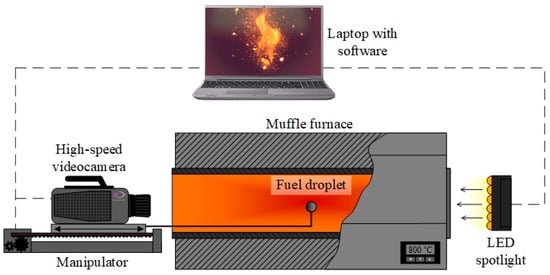
Figure 1.
Scheme of the experimental setup.
A motionless high-temperature air medium was created in the cavity of a Loiplf50/500-1200 tubular muffle furnace (Laboratory Equipment and Instruments, Russia). The inner diameter of the ceramic furnace tube is 50 mm; its length is 450 mm. The temperature varied in the range of 20–1200 °C and was controlled by a built-in type K thermocouple. Due to the fact that the ends of the tubular muffle furnace were open during the experiments, the gaseous products of the combustion of the fuels’ single droplets diffused into the environment. Composite fuel particle size (diameter of about 2 mm) is relatively small compared to the size of the internal volume of the muffle furnace ceramic tube (diameter 50 mm, length 450 mm). Therefore, in this study, oxygen concentration did not change significantly during the burnout.
Fuel particles/droplets (depending on the aggregate state with varying their initial temperatures over a wide range) of different compositions were dosed with the same mass of 5 mg and a diameter of about 2 mm. The mass of suspensions was determined using an AF-225DRCE analytical balance (ViBRA, Tokyo, Japan): the minimum recorded mass was 1 mg, the maximum recorded mass was 92 g, the discretization was 0.01 mg, and the accuracy class was Special (I) according to OIML R 76-1: 2006, IDT. Before the experiments, all fuels were thermostated at a constant temperature for 15 min. An Arctiko ULUF 15 freezer (ARCTIKO A/S, Esbjerg, Denmark) was used to cool fuels in the temperature range from minus 60 °C to minus 40 °C, and a thermostatic cell of a LOIP FT-205-25 liquid cryothermostat (Laboratory Equipment and Instruments, Saint Petersburg, Russia) was used in the temperature range from minus 20 °C to plus 60 °C.
In each series of the 5–8 experiments (Figure 1) conducted in identical initial conditions; the muffle furnace was heated to a given temperature (Tg). Single fuel particles/droplets located on a ceramic holder were introduced into the furnace cavity with a speed of no more than 0.1 m/s along the symmetry axis of the ceramic tube up to its center (Figure 1). The SPSH20-23017/2000Z manipulator (ZAO Mechatronic Product Factory, Moscow, Russia) simultaneously moved the ceramic holder and the high-speed video camera (Figure 1). This made it possible to record and analyze the processes during the entire induction period from fuel heating to its burnout. It should be noted that the experiments for different fuel compositions were conducted in identical conditions. The end openings of the muffle furnace (Figure 1) were open during ignition and combustion of the fuels. The oxygen concentration in the chamber was about 20.5% and did not change significantly during the burnout of a relatively small fuel particle/droplet. It should be noted that this work did not analyze the influence of the excess air coefficient on the fuel combustion characteristics.
The video recording system (Figure 1) consisted of a Phantom V411 color high-speed video camera (Vision Research, Wayne, NJ, USA) and a laptop computer with the Tema Automotive software (Image Systems AB, Linköping, Sweden). The shooting speed was at least 2000 fps at a resolution of 600 × 480 pixels. To enhance the image contrast of a fuel droplet and its fragments formed after dispersion, a MultiLed QT LED spotlight (GS Vitec GmbH, Bad Soden-Salmünster, Germany) with a 15° lens (luminous flux 12,000 Lumen (white), power 150 W) was installed at the opposite side of the muffle furnace (Figure 1) relative to the video camera location. Light intensity (0–100%) was controlled by a MultiLed G8 controller.
Ignition delay times td and burnout times tburn were determined from video recordings using original software developed in the Wolfram Mathematica programming envelope (Wolfram Research, Champaign, IL, USA). The ignition delay time of the composite fuel corresponded to the duration of the time period between two recorded events. The first event was the beginning of the induction period, which was controlled by the moment when the fuel particle was introduced into the muffle furnace (t = 0). The second event was the vapor–gas mixture ignition in the vicinity of the composite fuel droplet (t = td). The onset of this event corresponded to the moment when the first peak value of the controlled glow intensity in the video recording area was reached (Figure 2).
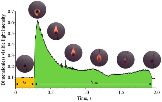
Figure 2.
Visualization of the video frame processing for determining the fuel ignition delay times.
The developed processing algorithm controlled the values of visible light emission intensity frame by frame in the entire video recording area. The ignition moment was determined automatically by a sharp jump in the luminosity intensity in the controlled vicinity of the fuel droplet (Figure 2). The burnout time of a fuel droplet (tburn) was recorded from the ignition moment to the end of combustion, which was characterized by a decrease in the glow intensity to the initial level—the luminosity value before fuel ignition (Figure 2). The systematic and random uncertainties of td and tburn connected with the video recording speed and the scatter of experimental data did not exceed 0.5% and 10%, respectively.
The size of the region where fine fragments and combustible gases burn out (dburn) after fuel droplet dispersion was calculated by averaging four values dburn = (d1 + d2 + d3 + d4)/4 [34] measured in different sections at the time when the projection area of the corresponding region on the focal plane was maximum (Figure 3). The systematic uncertainty of dburn connected with the lens features and the video camera settings (video recording resolution parameters) did not exceed 3%. The random uncertainty for a series of experiments performed under identical initial conditions was no more than 30%.
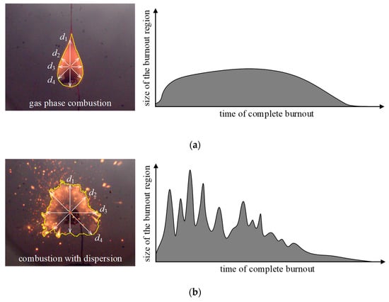
Figure 3.
Visualization of the video frame processing for determining the size of the burnout region of fuel components without dispersion (a) and with dispersion (b).
3. Results and Discussion
3.1. Initial Fuel Temperature
Studies of liquid [35] and gel [24] fuel combustion demonstrated that varying the initial fuel temperature (T0) or ambient temperature (Tg) does not affect the ignition and combustion mechanisms. However, these factors are decisive for the intensity of physical and chemical processes, and, consequently, for the duration of the main stages during the ignition process [33,35], the integral characteristic of which is the ignition delay time.
The ignition delay time (td) of the composite fuel consists of several stages of the induction period [24]. The first stage (Figure 4) is the heating of the fuel accompanied by the melting (if T0 is below the crystallization temperature of liquid fuel components), evaporation of liquid components, and release of volatiles from the solid combustible fuel components. This stage ends with the formation of a combustible vapor–gas mixture in the vicinity of a fuel droplet. The second stage is the exothermic reaction of the formed combustible vapor–gas mixture with the oxidizer. The duration of the second stage, as a rule, is no more than 5% of td [24]. Therefore, it is advisable to reduce the first stage of the induction period in order to reduce td of composite fuels, which is much greater than td of dry solid fuels (power-station coals) due to the content of solid and liquid components, including water, in the composition. In practice, to intensify the ignition process, fuel is preheated, which, generally, increases the efficiency of the energy production cycle [36], for example, by minimizing the chemical and mechanical underburning of fuels in the combustion chambers.
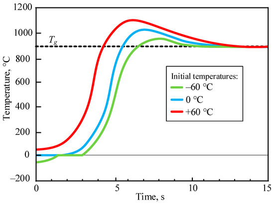
Figure 4.
Typical temperature trend in the droplet of composite fuel during heating based on [33].
In this work, the influence of the initial temperature of fuels (T0) on the combustion characteristics of droplets with varying the temperature of the heating source (Tg) was established. In real industrial boilers under different operating modes, the temperature in the furnace in the flame formation area varies from 700 °C (at relatively low loads) to 1000 °C (at relatively high loads). On this basis, our experimental studies of ignition and combustion of composite fuels at different initial fuel temperatures were conducted at temperatures of the heating source Tg = 700–1000 °C (with 100 °C increments).
Figure 5 presents the frames of the videograms illustrating the ignition moment of the fuel droplets with the initial temperatures of T0 = −60 °C and T0 = 60 °C at the identical temperature of the heating source Tg = 800 °C for compositions No. 1–No. 4.
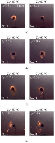
Figure 5.
Video frames of the ignition moment of composite fuel droplets at different initial fuel temperatures (left—T0 = −60 °C, right—T0 = 60 °C) and at the heating source temperature of Tg = 800 °C: (a) composition No. 1 (40% FC + 15% rapeseed oil + 45% water); (b) composition No. 2 (40% FC + 15% turbine oil + 45% water); (c) composition No. 3 (40% coal + 15% rapeseed oil + 45% water); (d) composition No. 4 (40% coal + 15% turbine oil + 45% water).
The video frames (Figure 5) clearly illustrate that the initial temperatures of composite fuels do not affect the mechanism of their ignition similarly to liquid or gel fuels [24,35]. Fuel compositions, which ignite according to the gas-phase mechanism at T0 = −60 °C, ignite similarly at T0 = 60 °C (for example, No. 1 and No. 2). Compositions igniting under dispersion conditions at T0 = −60 °C will disperse when droplets ignite with initial temperature of T0 = 60 °C. Therefore, it can be reasonably concluded that the patterns of physical and chemical transformations remain unchanged when varying in a wide range of initial temperatures of composite fuels, while only their duration and intensity change, which predictably affects the ignition delay times. It should be noted that T0 and td are inversely related in the considered temperature range (T0 = −60–60 °C).
The dependences of the ignition delay times of the compositions No. 1–No. 4 on their initial temperatures T0 that varied in the range between minus 60 °C and plus 60 °C are presented in Figure 6.
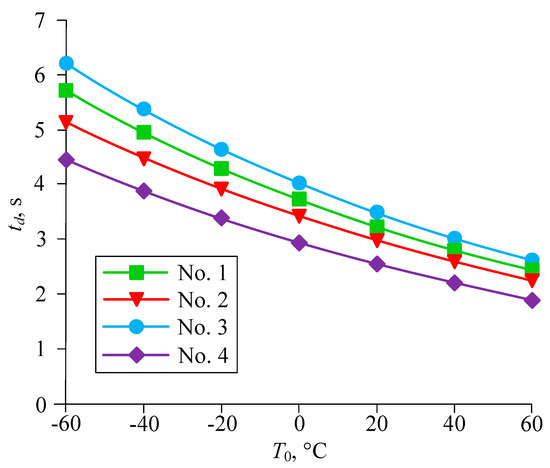
Figure 6.
Dependences of the ignition delay times of composite liquid fuels on their initial temperatures (T0) at the heating source temperature of Tg = 900 °C.
The combustion process was initiated in a high-temperature air environment at Tg = 900 °C. The behavior of the dependences obtained experimentally (Figure 5) confirms that an increase in the initial fuel temperature can effectively intensify ignition of a composite liquid fuel in practice, for example, when it is used as the main fuel for widely used coal-fired boilers. A decrease in td for the considered compositions connected with an increase in the initial fuel temperature from minus 60 °C to plus 60 °C, under identical heating conditions, was about 55%. It is also worth noting that the component composition of fuel suspensions has a more significant effect on the ignition delay time at relatively low initial fuel temperatures (Figure 6). Increasing the fuel temperature to T0 = 60 °C not only reduces the duration of the induction period, but also reduces the effect of the component composition of fuel on the ignition delay time (compared to the conditions at T0 = −60 °C). For example, the difference between td for fuel compositions No. 3 and No. 4 (Tg = 900 °C) at T0 = −60 °C was about 30%, and the difference at T0 = 60 °C was about 25%. Figures S1–S4 in the Supplementary material present the dependences of the ignition delay times for fuel compositions No. 1–No. 4 on the heating source temperature in the range of 700–1000 °C, with initial fuel temperatures varying from minus 60 °C to plus 60 °C with 20 °C increments.
An analysis of the results obtained (Figure 6 and Figures S1–S4) allows us to conclude that it is typical that the ignition delay time decreases by 60–75% (depending on the composition) with an increase in the heating source T0 from 700 °C to 1000 °C for the considered compositions (No. 1–No. 4) of composite liquid fuel with varying initial temperatures from minus 60 °C to plus 60 °C.
The experimental results illustrate (Figures S1–S4) that the compositions containing turbine oil (No. 2, No. 4) ignite earlier than the compositions with the addition of rapeseed oil with the same volume (No. 1, No. 3) over the entire range of temperature variations of T0 and Tg. This is due to the physical properties of the oils. Turbine oil has a lower vaporization heat and lower boiling and autoignition temperatures. These characteristics together affect the ignition delay times of identical fuel compositions with the addition of different combustible liquids.
The fuel composition No. 4 (Figure S4) demonstrates the minimum ignition delay times. This composition ignites under droplet dispersion conditions (Figure 5d) with the formation of many finely dispersed components flying apart in the radial direction. This process with intensive heating of a composite fuel droplet makes it possible to achieve ignition conditions faster due to a multiple increase in the free heat exchange surface, the evaporation of liquid components, and the release of gaseous products during the thermal decomposition of the solid components. At the same time, composition No. 4 is the least sensitive to changes in the initial fuel temperature: with an increase in the initial temperature from minus 60 °C to plus 60 °C, the ignition delay time decreases by 60% at Tg = 700 °C and by 55% at Tg = 1000 °C.
In turn, fuel composition No. 2, based on FC with the addition of turbine oil, is the most sensitive both to changes in the initial fuel temperature and to changes in the heating source temperature (Figure S2). Increasing the ambient air temperature from 700 °C to 1000 °C reduces the ignition delay time by 75% at T0 = −60 °C and by 65% at T0 = 60 °C. With identical values of Tg, an increase in the initial fuel temperature leads to a decrease in the ignition delay time by 70% at Tg = 700 °C and by 55% at Tg = 1000 °C.
It can be concluded that it is possible to achieve a significant intensification of the fuel ignition process by cumulatively increasing the heating source temperature Tg (from 700 °C to 1000 °C) and the initial fuel temperature T0 (from minus 60 °C to plus 60 °C). Moreover, the reduction in the ignition delay time will be about 7.5 times. The result obtained is important for practice, for example, in the case of switching coal-fired boilers to composite fuel or when designing furnaces for new boilers, when minimizing the duration of ignition and fuel burnout processes is necessary to reduce the dimensions of furnaces and combustion chambers, as well as to increase the completeness of fuel components burnup. Droplet dispersion under its intense heating conditions is one of the promising ways to intensify the combustion process of multicomponent fuels [34,37].
3.2. Enhancement of Fuel Ignition
From experiments, the main significant factors (properties of liquid components, concentrations of solid and liquid components) that affect the implementation of droplet dispersion under intense heating conditions were established. For the group of compositions: coal + oil + water + highly flammable liquid (gasoline, diesel fuel, kerosene, formic acid), the ignition and dispersion characteristics of 2 mm droplets were obtained at one initial fuel temperature T0 = 20 °C and one heating source temperature Tg = 900 °C. Two groups of fuel compositions (Table 5) differ in oil concentrations (in both groups, the mass fraction of coal is the same and equal to 40%): the 1st group contains 15% rapeseed oil and 45% water, and the 2nd group contains 40% rapeseed oil and 20% water. In addition, 5% highly flammable liquids (HFL) were added to the basic fuel compositions of both groups. Their main characteristics are given in Table 6.
Table 5.
Compositions of composite fuels with the addition of flammable liquids.
Table 6.
Main characteristics of highly flammable liquids [38,39,40,41,42].
Figure 7 shows typical video frames of ignition and combustion of considered composite fuels (Table 5) at one typical initial fuel temperature T0 = 20 °C in high-temperature air at Tg = 900 °C.
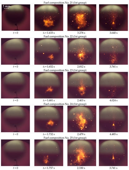
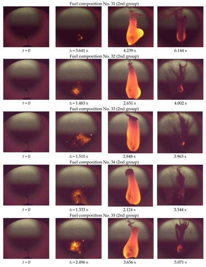
Figure 7.
Typical video frames of ignition and combustion of composite fuel droplets at T0 = 20 °C, Tg = 900 °C.
There are different dominant ignition and combustion mechanisms in the two groups of composite fuel compositions due to the different mass ratio of their components (Table 5). It is guaranteed that the fuel droplet disperses both during ignition and burnout (Figure 7) at an oil:water ratio of 1:3 (1st group). When the oil:water ratio is 2:1 (2nd group, the droplet moderately disperses, predominantly during the ignition process, with the gas-phase combustion mechanism of the components predominating (Figure 7). The addition of highly flammable liquids to fuel compositions (gasoline, diesel fuel, kerosene, formic acid) with a concentration of 5% wt. influences the patterns and characteristics of the process under study.
The averaged ignition delay times for composite fuels with and without HFL are presented in Figure 8.
Figure 8.
Ignition delay times of composite fuel droplets with different HFL additives.
Based on the results obtained, it can be concluded that the concentration of the main combustible liquid (rapeseed oil) significantly affects the ignition delay times. With an increase in concentration from 15% to 40% (No. 21 and No. 31), due to a decrease in the concentration of the liquid non-combustible component (water), the ignition delay times decrease by a factor of 2.3. For the 2nd group’s compositions that contain 40% of the main combustible liquid, the addition of 5% HFL does not significantly affect the change in the ignition delay time due to the high concentration of the volatile component.
Meanwhile, for the compositions of the 1st group that contain 15% of the main combustible liquid, the addition of even 5% HFL reduces the ignition delay times by 35–65%. The greatest decrease is found for the composition containing 5% diesel fuel due to its physico-chemical characteristics. Diesel fuel, in comparison with other flammable liquids, has the lowest vaporization heat (Table 6). Therefore, a vapor–gas mixture in the vicinity of a fuel droplet forms faster, which reduces the ignition delay time. The addition of formic acid (No. 25) to the initial fuel composition of the 1st group containing 15% rapeseed oil and 45% water has a less significant effect (compared to other HFL)—the ignition delay time is reduced by only 1.5 times. This is due to the fact that formic acid has the highest vaporization heat (Table 6) compared to other HFL, but its value is still less than that of rapeseed oil. As a result, the formation of the vapor–gas mixture is faster than that of composition No. 21, but slower than that of compositions No. 22–No. 24, which is the reason for the difference in ignition delay times.
The burnout times of composite fuels (Figure 9) depend on the combustion mechanisms.
Figure 9.
Burnout times of composite fuel droplets with different HFL additives.
Dispersion of composite fuel droplets significantly reduces the burnout time, since exothermic reactions are more intense and proceed in a larger region (Figure 10).
Figure 10.
Average sizes of region where components of composite fuels with different HFL additives burn out.
Previous studies [37] show that composite liquid fuels containing 40% oil in their composition are guaranteed to disperse during burnout. HFL were added to the fuel composition to intensify this phenomenon. However, the addition of 5% HFL to the compositions of the 2nd group containing a relatively large amount (40%) of the main combustible liquid (No. 31–No. 35) does not have a significant effect on enhancing the fuel droplet dispersion. The burnout times change by 5–15% (Figure 9) and the size of the burnout region by 1–5% (Figure 10). Meanwhile, the addition of HFL to the compositions of the 1st group (No. 21–No. 25) with a low content (15%) of rapeseed oil has a significant effect on the dispersion intensification. The addition of 5% diesel fuel reduces the burnout time by 40% due to an increase in the average diameter of the burnout region by a factor of 1.7 (Figure 10). This is due to the fact that most of the used HFL (gasoline, diesel, kerosene) is dispersed (Table 6) and, therefore, increases the dispersed component of the fuel mixture and enhances the dispersion mechanism [37].
The results obtained are the basis for the development of industrial technologies for the use of composite fuels in coal-fired boilers, since composite fuels have a number of limitations compared to coal:
- higher limit temperatures for the guaranteed initiation of combustion in the furnace;
- longer induction period and low reactivity at the initial stage of combustion;
- longer time for the complete burnout of fuel components under flaring conditions;
- the need to re-equip fuel preparation and fuel supply systems;
- low caloric value and combustion temperature due to the relatively high content of water (carrier medium) in composite fuels;
- low proportion of carbon in composite fuels compared to coal fuels;
- low stability of composite fuels, which requires the use of chemical stabilizers;
- stricter requirements of transportation and storage demanding fuel tanks and pipelines to be equipped with heating systems when operating under negative climatic temperatures.
4. Practical Application
The use of composite fuels at existing thermal power plants will definitely be associated with a reduction in the cost of purchasing high-quality coal fuel and a decrease in anthropogenic emissions into the atmosphere with flue gases, but will also be accompanied by a decrease in energy production efficiency due to longer ignition delay and burnout times of composite fuels compared to widely used dry solid fuels [18]. To solve this problem, several directions can be distinguished (Figure 11).
Figure 11.
Practical solutions to the problem of long ignition delay times for composite fuels.
Firstly, it is possible to increase the sizes of the combustion chamber to ensure guaranteed ignition and the complete burnout of high-moisture fuel, which is evidently associated with the replacement of the boiler unit and significant capital costs. Secondly, to intensify heating of composite fuel droplets and reduce the ignition delay time, it is possible to increase the temperature in the combustion chamber by increasing the kindling time. This solution will inevitably increase the consumption of starting fuel, increase the operating costs of the station, and also increase the concentration of anthropogenic emissions (primarily nitrogen oxides) in flue gases [14,15].
The only solution that is not associated with high capital and operating costs is to change the composition of the composite fuel to implement the phenomenon of droplet dispersion during ignition and burnout (Figure 11). This approach will make it possible to burn multicomponent fuels of suspensions in coal-fired boilers under conditions which are typical of design solid fuels. The use of additives for the composite fuel to ensure the dispersion implementation can contribute to an increase in the concentrations of gaseous anthropogenic emissions. However, compared to dry coals, the deterioration of environmental performance is guaranteed not to exceed the maximum allowable standard emissions of pollutants from power plants for burning solid fuels [15].
5. Conclusions
Based on the experimental studies of single droplets of composite fuels with different compositions (at initial temperatures from minus 60 °C to plus 60 °C) in a motionless high-temperature air medium of 700–1000 °C, it was found that the minimum differences in ignition delay times at conditions close to the limiting ones were 2–3.5 times. By cumulatively increasing the heating source temperature (from 700 °C to 1000 °C) and the initial fuel temperature (from minus 60 °C to plus 60 °C), it was possible to reduce the ignition delay time by 7.5 times. The initial temperature was substantiated, at which the fuel components did not yet chemically react (in the composition of the suspension itself); however, at the same time, the ignition delay times of fuel droplets were significantly (up to 3 times) reduced. The initial fuel temperature of 60 °C was the limit; a further increase in this temperature lead to an intensification of phase transition of liquid components (water and oil). In terms of practical applications, the significant evaporation of water from composite fuel at the stage of its preparation for combustion is undesirable due to the deterioration of the environmental performance of the combustion process.
To solve the problem of long-term ignition of a composite liquid fuel compared to dry coal fuel for the purpose of its practical application at thermal power facilities, it is necessary to intensify this process. A promising direction for intensifying combustion, including ignition, is the implementation of droplet dispersion into a large number of finely dispersed fragments during intense heating. Additional HFL added to the fuel compositions characterized by droplet dispersion under heating conditions intensifies the process if the content of the main liquid combustible component does not exceed the concentration of the liquid non-combustible component. For these compositions, the addition of even 5% wt. HFL is characterized by the intensification of ignition and droplet burnout by almost 2 times (it reduces the ignition delay time by 35–65%, reduces the burnout time by 20–40%, and increases the size of the dispersion region by 20–70%). Diesel fuel as an intensifying additive is characterized by the best influence on the main ignition characteristics—up to 70%. At the same time, the addition of 5% HFL to compositions with a high concentration of a liquid combustible component (40%) does not have a positive effect on the ignition and dispersion characteristics—they either increase by 1–15%, as the ignition delay time and burnout time, or change in uncertainty limits in comparison with the original fuel, as the diameter of the burnout region.
The results obtained are the basis for the measures development for the modernization of technologies for the solid and liquid fuels combustion, which can be partially replaced by composite fuels. Thanks to the latter, it is possible to reduce the negative impact on the environment of both the combustible waste stored at landfills and anthropogenic emissions with flue gases. In addition, composite fuels have better energy and economic characteristics compared to traditional solid and liquid fuels. However, a positive effect is achieved only with the scientific substantiation of the fuel’s component composition (especially when using local energy resources) and the modes of their combustion in the furnaces of operated and designed boilers. To date, the scientific community has created a large information database with the characteristics of both composite fuels (rheological, energy) and their combustion processes (ignition delay times, burnup times, composition of flue gases and ash). It is the basis for developing new and improving existing mathematical models that describe a group of interrelated physical and chemical processes in a condensed phase and a gaseous medium. A large set of experimental research results and numerical simulations will make it possible to proceed to full-scale tests aimed at the development and implementation of practical technologies for the combustion of composite fuels based on solid (coal processing waste, coal) and liquid (water, oil) energy resources by power generating installations of industrial heat power engineering. Without a doubt, the development of rational engineering solutions requires the use of big data analytics. In particular, neural network methods should help to extract results from a large amount of accumulated information that will contribute to the most efficient waste disposal with the generation of useful energy.
Supplementary Materials
The following supporting information can be downloaded at: https://www.mdpi.com/article/10.3390/app13063501/s1, Figure S1: Dependences of the ignition delay times for composition No. 1 (40% FC + 15% rape-seed oil + 45% water) on ambient temperature at various initial temperatures; Figure S2: Dependences of the ignition delay times for composition No. 2 (40% FC + 15% turbine oil + 45% water) on ambient temperature at various initial temperatures; Figure S3: Dependences of the ignition delay times for composition No. 3 (40% coal + 15% rape-seed oil + 45% water) on ambient temperature at various initial temperatures; Figure S4: Dependences of the ignition delay times for composition No. 4 (40% coal + 15% tur-bine oil + 45% water) on ambient temperature at various initial temperatures.
Author Contributions
Conceptualization, D.G.; data curation, A.P.; funding acquisition, D.G.; formal analysis, A.N.; investigation, K.P.; software, D.K.; methodology, A.P.; project administration, D.G.; writing—original draft, K.P.; writing—review and editing, D.K. All authors have read and agreed to the published version of the manuscript.
Funding
The study was supported by National Research Tomsk Polytechnic University development program Priority-2030 (Priority-2030-NIP/EB-03 8-1308-2022).
Institutional Review Board Statement
Not applicable.
Informed Consent Statement
Not applicable.
Data Availability Statement
Data available within the article or its supplementary materials.
Conflicts of Interest
The authors declare no conflict of interest. The funders had no role in the design of the study; in the collection, analyses, or interpretation of data; in the writing of the manuscript; or in the decision to publish the results.
Abbreviations
| HFL | highly flammable liquid |
| FC | filter cake |
| Nomenclature | |
| Ad | ash content, % |
| Cdaf, Hdaf, Ndaf, Odaf, Sdaf | fraction of carbon, hydrogen, nitrogen, oxygen, sulfur in the sample converted to a dry ash free state, % |
| d | diameter, mm |
| Qas,V | higher heating value, J/kg |
| T | temperature, °C |
| Ta | heated air temperature, °C |
| t | time, s |
| td | ignition delay time, s |
| Vdaf | volatile content, % |
| Wa | humidity, % |
References
- Yang, W.; Pudasainee, D.; Gupta, R.; Li, W.; Wang, B.; Sun, L. Particulate Matter Emission during MSW/RDF/WW Combustion: Inorganic Minerals Distribution, Transformation and Agglomeration. Fuel Process. Technol. 2022, 228, 107166. [Google Scholar] [CrossRef]
- Wang, B.; Li, W.; Ma, C.; Yang, W.; Pudasainee, D.; Gupta, R.; Sun, L. Synergistic Effect on the Co-Gasification of Petroleum Coke and Carbon-Based Feedstocks: A State-of-the-Art Review. J. Energy Inst. 2022, 102, 1–13. [Google Scholar] [CrossRef]
- Rago, Y.P.; Collard, F.X.; Görgens, J.F.; Surroop, D.; Mohee, R. Co-Combustion of Torrefied Biomass-Plastic Waste Blends with Coal through TGA: Influence of Synergistic Behaviour. Energy 2022, 239, 121859. [Google Scholar] [CrossRef]
- Han, H.; Li, A.; Li, H.; Hu, S.; Wang, Y.; He, L.; Xu, J.; Hu, X.; Su, S.; Xiang, J. Roles of Calcium Oxide on the Evolution of Substituted Polycyclic Aromatic Hydrocarbons Released from Sewage Sludge Pyrolysis. J. Clean. Prod. 2021, 317, 128324. [Google Scholar] [CrossRef]
- Chintakanan, P.; Vitidsant, T.; Reubroycharoen, P.; Kuchonthara, P.; Kida, T.; Hinchiranan, N. Bio-jet Fuel Range in Biofuels Derived from Hydroconversion of Palm Olein over Ni/Zeolite Catalysts and Freezing Point of Biofuels/Jet A-1 Blends. Fuel 2021, 293, 120472. [Google Scholar] [CrossRef]
- Sukjit, E.; Maneedaeng, A. Effect of Mixed Nonionic Surfactants on Microemulsion Phase Boundary, Fuel Property, and Engine Performance of Biofuels. Energy Rep. 2022, 8, 722–730. [Google Scholar] [CrossRef]
- Nagappan, M.; Babu, J.M. In Ternary Blend Fuelled Diesel Engines, Nanoparticles are Used as an Additive in Biofuel Production and as a Fuel Additive: A review. Mater. Today Proc. 2023, in press. [Google Scholar] [CrossRef]
- Mahmudul, H.M.; Akbar, D.; Rasul, M.G.; Narayanan, R.; Mofijur, M. Estimation of the Sustainable Production of Gaseous Biofuels, Generation of Electricity, and Reduction of Greenhouse Gas Emissions Using Food Waste in Anaerobic Digesters. Fuel 2022, 310, 122346. [Google Scholar] [CrossRef]
- Sadykov, V.A.; Eremeev, N.F.; Sadovskaya, E.M.; Shlyakhtina, A.V.; Pikalova, E.Y.; Osinkin, D.A.; Yaremchenko, A.A. Design of Materials for Solid Oxide Fuel Cells, Permselective Membranes, and Catalysts for Biofuel Transformation into Syngas and Hydrogen Based on Fundamental Studies of Their Real Structure, Transport Properties, and Surface reactivity. Curr. Opin. Green Sustain. Chem. 2022, 33, 100558. [Google Scholar] [CrossRef]
- Piazza, V.; Junior, R.B.S.; Luccisano, G.; Pietrogiacomi, D.; Groppi, G.; Gazzoli, D.; Beretta, A. H2 from Biofuels and Carriers: Gas-Phase and Surface Ethanol Conversion Pathways on Rh/Al2O3 Investigated by Annular microreactor Coupled with Raman and FTIR Spectroscopy. J. Catal. 2022, 413, 184–200. [Google Scholar] [CrossRef]
- Jin, Y.; Luo, H.; Zhang, G.; Zhai, C.; Ogata, Y.; Matsumura, Y.; Ichikawa, T.; Nakashimada, Y.; Kim, W.; Nishida, K. Ignition Timing Effect on the Combustion Performance of Hydrogen Addition in Methane Fermentation Gas in a Local Energy System. Fuel 2022, 324, 124714. [Google Scholar] [CrossRef]
- Safiullah; Chandra Ray, S.; Nishida, K.; McDonell, V.; Ogata, Y. Effects of Full Transient Injection Rate and Initial Spray Trajectory Angle profiles on the CFD Simulation of Evaporating Diesel Sprays—Comparison between Singlehole and Multi Hole Injectors. Energy 2023, 263, 125796. [Google Scholar] [CrossRef]
- Muthuraman, M.; Namioka, T.; Yoshikawa, K. Characteristics of Co-Combustion and Kinetic Study on Hydrothermally Treated Municipal Solid Waste with Different Rank Coals: A Thermogravimetric Analysis. Appl. Energy 2010, 87, 141–148. [Google Scholar] [CrossRef]
- Nyashina, G.S.; Kurgankina, M.A.; Strizhak, P.A. Environmental, Economic and Energetic Benefits of Using Coal and Oil Processing Waste Instead of Coal to Produce the Same Amount of Energy. Energy Convers. Manag. 2018, 174, 175–187. [Google Scholar] [CrossRef]
- Kurgankina, M.A.; Nyashina, G.S.; Strizhak, P.A. Prospects of Thermal Power Plants Switching from Traditional Fuels to Coal-Water Slurries Containing Petrochemicals. Sci. Total Environ. 2019, 671, 568–577. [Google Scholar] [CrossRef] [PubMed]
- Bhuiyan, A.A.; Blicblau, A.S.; Islam, A.K.M.S.; Naser, J. A Review on Thermo-Chemical Characteristics of Coal/Biomass Co-Firing in Industrial Furnace. J. Energy Inst. 2018, 91, 1–18. [Google Scholar] [CrossRef]
- Gaber, C.; Wachter, P.; Demuth, M.; Hochenauer, C. Experimental Investigation and Demonstration of Pilot-Scale Combustion of Oil-Water Emulsions and Coal-Water Slurry with Pronounced Water Contents at Elevated Temperatures with the Use of Pure Oxygen. Fuel 2020, 282, 118692. [Google Scholar] [CrossRef]
- Glushkov, D.O.; Kuznetsov, G.V.; Paushkina, K.K.; Shabardin, D.P. The Main Elements of a Strategy for Combined Utilization of Industrial and Municipal Waste from Neighboring Regions by Burning it as Part of Composite Fuels. Energies 2018, 11, 2534. [Google Scholar] [CrossRef]
- Pinchuk, V.A. The Main Regularities of Ignition and Combustion of Coal-Water Fuels Produced from Brown, Flame and Gas Coals. Int. J. Eng. Res. Afr. 2018, 37, 141–157. [Google Scholar] [CrossRef]
- Pinchuk, V.A.; Sharabura, T.A.; Kuzmin, A.V. Experimental Investigation of Thermal Conductivity and Heat Capacity of Coal-Water Fuel. Int. J. Energy A Clean Environ. 2016, 17, 165–185. [Google Scholar] [CrossRef]
- Kong, D.; Zhang, Z.; Ping, P.; He, X.; Yang, H. Effects of the Initial Fuel Temperature on Burning Behavior of Crude Oil Pool Fire in Ice Cavities. Exp. Heat Transf. 2018, 31, 436–449. [Google Scholar] [CrossRef]
- Ji, J.; Lin, S.; Zhao, C.; Li, K.; Gao, Z. Experimental Study on Initial Temperature Influence on Flame Spread Characteristics of Diesel and Gasoline–Diesel Blends. Fuel 2016, 178, 283–289. [Google Scholar] [CrossRef]
- Chen, B.; Lu, S.X.; Li, C.H.; Kang, Q.S.; Lecoustre, V. Initial Fuel Temperature Effects on Burning Rate of Pool Fire. J. Hazard. Mater. 2011, 188, 369–374. [Google Scholar] [CrossRef] [PubMed]
- Glushkov, D.O.; Kuznetsov, G.V.; Nigay, A.G.; Yanovsky, V.A. Influence of Gellant and Drag-Reducing Agent on the Ignition Characteristics of Typical Liquid Hydrocarbon Fuels. Acta Astronaut. 2020, 177, 66–79. [Google Scholar] [CrossRef]
- McAllister, S.; Chen, J.Y.; Fernandez-Pello, A.C. Fundamentals of Combustion Processes; Mechanical Engineering Series; Springer: New York, NY, USA, 2011; Volume 58, ISBN 978-1-4419-7942-1. [Google Scholar]
- ISO 562:2010; Hard Coal and Coke—Determination of Volatile Matter. ISO: Geneva, Switzerland, 2010.
- ISO 1171:2010; Solid Mineral Fuels—Determination of Ash. ISO: Geneva, Switzerland, 2010.
- ISO 11722:1999; Solid Mineral Fuels—Hard coal—Determination of Moisture in the General Analysis Test Sample by Drying in nitrogen. ISO: Geneva, Switzerland, 1999.
- ISO 1928:2009; Solid Mineral Fuels—Determination of Gross Calorific Value by the Bomb Calorimetric Method and Calculation of Net Calorific Value. ISO: Geneva, Switzerland, 2009.
- ASTM D240-19; Standard Test Method for Heat of Combustion of Liquid Hydrocarbon Fuels by Bomb Calorimeter. ASTM International: West Conshohocken, PA, USA, 2000.
- Valiullin, T.R.; Egorov, R.I.; Strizhak, P.A. Perspectives of the Use of Rapeseed Oil for the Doping of Waste-Based Industrial Fuel. Energy Fuels 2017, 31, 10116–10120. [Google Scholar] [CrossRef]
- Kuznetsov, G.V.; Romanov, D.S.; Vershinina, K.Y.; Strizhak, P.A. Rheological Characteristics and Stability of Fuel Slurries Based on Coal Processing Waste, Biomass and Used Oil. Fuel 2021, 302, 121203. [Google Scholar] [CrossRef]
- Romanov, D.S.; Vershinina, K.Y.; Dorokhov, V.V.; Strizhak, P.A. Rheology, Ignition, and Combustion Performance of Coal-Water Slurries: Influence of Sequence and Methods of Mixing. Fuel 2022, 322, 124294. [Google Scholar] [CrossRef]
- Feoktistov, D.V.; Glushkov, D.O.; Kuznetsov, G.V.; Orlova, E.G.; Paushkina, K.K. Ignition and Combustion Enhancement of Composite Fuel in Conditions of Droplets Dispersion during Conductive Heating on Steel Surfaces with Different Roughness Parameters. Fuel 2022, 314, 122745. [Google Scholar] [CrossRef]
- Antonov, D.V.; Kuznetsov, G.V.; Fedorenko, R.M.; Strizhak, P.A. Micro-Explosion of a Two-Component Droplet: How the Initial Temperature of the Water Core Affects the Breakup Conditions and Outcomes. Powder Technol. 2021, 382, 378–387. [Google Scholar] [CrossRef]
- Gogoi, T.K. A Combined Cycle Plant with Air and Fuel Recuperator for Captive Power Application, Part 1: Performance Analysis and Comparison with Non-Recuperated and Gas Turbine Cycle with Only Air Recuperator. Energy Convers. Manag. 2014, 79, 771–777. [Google Scholar] [CrossRef]
- Glushkov, D.O.; Feoktistov, D.V.; Kuznetsov, G.V.; Batishcheva, K.A.; Kudelova, T.; Paushkina, K.K. Conditions and Characteristics of Droplets Breakup for Industrial Waste-Derived Fuel Suspensions Ignited in High-Temperature Air. Fuel 2020, 265, 116915. [Google Scholar] [CrossRef]
- Parrilla, J.; Cortes, C. Modelling of Droplet Burning for Rapeseed Oil as Liquid Fuel. Renew. Energy Power Qual. J. 2007, 1, 79–86. [Google Scholar] [CrossRef]
- Yaws, C.L.; Gabbula, C. Yaws’ Handbook of Thermodynamic and Physical Properties of Chemical Compounds; Knovel: Norwich, NY, USA, 2003; ISBN 978-1-59124-444-8. [Google Scholar]
- Laza, T.; Bereczky, Á. Basic Fuel Properties of Rapeseed Oil-Higher Alcohols Blends. Fuel 2011, 90, 803–810. [Google Scholar] [CrossRef]
- Hilder, M.H. The Solubility of Water in Edible Oils and fats. J. Am. Oil Chem. Soc. 1968, 45, 703–707. [Google Scholar] [CrossRef]
- ILO International Chemical Safety Cards (ICSCs). Available online: https://www.ilo.org/safework/info/publications/WCMS_113134/lang--en/index.htm (accessed on 5 May 2022).
Disclaimer/Publisher’s Note: The statements, opinions and data contained in all publications are solely those of the individual author(s) and contributor(s) and not of MDPI and/or the editor(s). MDPI and/or the editor(s) disclaim responsibility for any injury to people or property resulting from any ideas, methods, instructions or products referred to in the content. |
© 2023 by the authors. Licensee MDPI, Basel, Switzerland. This article is an open access article distributed under the terms and conditions of the Creative Commons Attribution (CC BY) license (https://creativecommons.org/licenses/by/4.0/).