Abstract
The new Austrian tunnelling method (NATM) and tunnel boring machine (TBM) are methods for excavating underground spaces. The NATM construction method has noise and vibration problems, and excavation using TBM has the disadvantage of high initial cost and is limited by ground conditions. A parallel TBM and NATM construction method has been developed to overcome these limitations. However, research on the TBM and NATM parallel construction method is lacking, and it is crucial to identify the applicability of the TBM and NATM parallel construction method in advance by applying it to various ground and blasting conditions. In this study, based on the vibration measurement data of the excavation site using the NATM construction method, the vibration measurement values generated when excavating the top surface using the existing NATM construction method and the TBM and NATM parallel construction methods were compared. Lastly, the vibration reduction effect of the two construction methods was analysed according to the tunnel excavation depth and tunnel size through 3D numerical analysis. As the depth of tunnel excavation increases, the vibration at the ground surface is reduced by up to 83%. In addition, as the ratio of the size of the blasting surface with NATM and the excavation surface with TBM is closer to 1.0, the vibration decreases.
1. Introduction
With the development of urban areas, the above-ground space has reached a saturation point, and as an alternative to this, the development of underground space is receiving significant attention. In recent years, underground spaces have been used not only for transportation infrastructure, but also for underground facilities such as power stations, communications, water supply and sewage, and complex residential and cultural areas.
Excavation methods using the new Austrian tunnelling method (NATM) and tunnel boring machine (TBM) are representative construction methods for excavating such underground spaces. NATM is a method based on equilibrium theory, which leads to new equilibrium elastic or elasto-plastic states, contrary to conventional tunnels designed and constructed based on the relaxation load theory [1]. NATM is advantageous for cross-sectional construction, and realises excavation relatively cost-effectively in various ground conditions. However, it has the disadvantages of high overbreaks, low excavation velocity, and noise and vibration due to blasting. Compared to the blasting construction method, mechanised excavation using TBM has the advantage of low noise and vibration, higher safety, and cost- and time-effectiveness in long tunnels. However, it is difficult to change the excavation section, and the initial investment cost is high. Thus, TBM is not economical for tunnels with short distances.
To compensate for the disadvantages of the blasting construction method and mechanical excavation using TBM, several construction methods have been developed, and a representative construction method is the TBM and NATM parallel excavation method. TBM and NATM parallel excavation is superior in that it exhibits low noise and vibration as TBM mechanical excavation, and economic feasibility and flexible excavation cross-section of blasting can be realised. TBM and NATM parallel excavation is employed in performing preliminary excavation using a small-diameter TBM, and simultaneously enlarging the excavation cross-section through back explosive blasting according to the desired tunnel size and shape. This method can obtain a free surface and exclude centre-cut blasting that causes vibration, which significantly reduces noise and vibration. Additionally, it has the advantage of enabling follow-up measurements according to the condition of the bedrock, because it is possible to investigate the ground condition before wide excavation through the TBM preceding tunnel.
However, there is a lack of research on TBM and NATM parallel excavation according to various ground conditions, tunnel depth, size and shape, and the effect of back blasting using explosive charges on the front TBM mechanical device and preceding tunnel. Moreover, the required minimum offset from the blasting point needs further clarification. Such results are expected to enhance cost-effectiveness by securing the stability of the construction method and shortening the existing construction period.
In this study, 3D numerical analysis was used based on the vibration data measured on the upper ground surface of the site using the NATM blasting construction method to compare the existing blasting method and the TBM and NATM parallel construction method. For the application of the TBM and NATM parallel construction method, the vibrations generated during the blasting of the upper halves were compared, and the reduction rate of vibrations measured on the ground surface according to the excavation depth of the tunnel was analysed. In addition, based on the experiment conducted in [2], the blasting vibration reduction effect due to pilot tunnel sizes for a total of six cases was predicted by modelling pilot tunnels of 3.0 m and 5.0 m excavated using TBM, and 10.0 m, 15.0 m, and 20.0 m using NATM tunnels. This data was compared to the standard about vibration. This study suggests the appropriate depth and size of the tunnel excavation. It is expected to increase reliability and safety.
2. Literature Review
Due to the increasing urban development worldwide, the demand for underground space facilities is also increasing, and excavation methods, equipment, and related regulations for safer and more economical construction are continuously being studied. As of 2020, a total of 3526 road and railway tunnels were built in South Korea, with a total length of 3062.3 km [3]. In 2018, South Korea enacted the Special Act on Underground Safety, and mandated underground safety impact assessment and design. To this end, construction companies independently have been managing subsidence, vibration, and noise more strictly than domestic standards [4].
In Korea, the NATM construction method has been continuously used, starting with some subway constructions in Seoul and Busan in 1983. However, the NATM method has faced civil complaints due to blasting vibration and noise, and a poor working environment due to dust and gas. Unexpected geologic characteristics, planning and specification problems, calculation and numerical errors, construction problems, and management and control problems can cause collapse accidents caused by explosive blasting in NATM [5,6].
Ref. [7] developed a drilling path and ground exploration complex system for identifying the geological characteristics of the excavation surface. In this case, the MSP method was used for drilling a large-diameter armed hole to reduce tunnel blasting vibration. Ref. [8] reviewed major disaster-influencing factors when excavating NATM tunnels. The measurement indicators were specified through literature and expert surveys, and those were prioritized in order of disaster impact factors with the greatest impact through surveys and analysis. In addition, many studies have been conducted to overcome the disadvantages of blasting vibration and NATM [9,10].
TBM, which was used to excavate underground in the River Thames in England in 1825, rotates a cutter head equipped with several disc cutters to crush and excavate bedrock, and has advantages such as higher velocity, improved safety, and reduced vibration and noise compared to the NATM construction method. However, it has disadvantages such as expensive equipment, limited excavation cross-section and route, and difficulty in preparing for stratum change. Thus, extensive research on tunnel excavation using TBM is required [11,12,13,14]. Ref. [15] studied the effects on the torque, thrust force, chamber pressure, and upward force acting on the TBM due to excavating complex ground. The coupled method of the DEM (discrete element method) and FDM (finite difference method) was used for the TBM excavation model. Ref. [16] studied that the face pressure of an EPB shield TBM was predicted using the geological and operational data acquired from a domestic TBM tunnel site.
Consequently, the TBM and NATM parallel construction method, which was first developed by the Italian Railways in 1982 as a method to solve these disadvantages, can check unexpected geological characteristics through TBM pre-excavation, and has the advantages of securing a free surface due to the pilot tunnel, reducing vibration and noise due to the exclusion of centre cut blasting, and diversifying the size and shape of the tunnel by rear NATM excavation. It was shown in ref. [17] that it is possible to reduce construction costs by 50% per unit volume using TBM and NATM parallel construction compared to NATM blasting in good quality rock conditions. Moreover, it was shown in ref. [18] that when a small diameter of 3.5–5.0 m is employed in the TBM pilot tunnel, the constructability becomes excellent. Specifically, a 20% construction cost reduction can be realised due to the preliminary ground investigation of the pilot tunnel. In ref. [2], 3D numerical analysis was used to probe the impact of blasting vibration on TBM and backup devices depending on the type of bedrock and the power factor using the TBM and NATM parallel construction method. It was confirmed that the vibration velocity increased in high-density bedrock more than that in mud and soil. Additionally, the minimum offset required between the blasting point and the TBM was presented in comparison with permitted domestic blasting regulations.
Thus, in this study, the vibration data of a site using NATM blasting were measured, and numerical analysis was performed with the same ground and tunnel conditions as those of the measured site. However, the effects of torque, thrust force, chamber pressure, and upward force acting on the TBM were not considered. Moreover, the lining was not considered because of simulating TBM and NATM blasting in uniform good rock mass [19]. In this study, 3D numerical analysis was performed for the effect of blasting vibration according to four tunnel depths and six tunnel sizes. This was to find the optimal conditions for applying TBM and NATM parallel excavation. These optimal conditions are expected to help with economical and safe tunnel excavation.
3. Field Measurement of Blasting Vibration
3.1. Site Status
Although it is ideal to perform analyses based on a large number of field data, it is not efficient and cost-effective. Thus, we performed numerical analysis for various cases (tunnel depth and size) under the same ground and blasting conditions based on minimum field data. First, to measure blasting vibration data at the site, a measuring instrument was installed on the upper ground surface of the GTX-A underground express railway construction site, and the measuring instrument installation position was measured at a point 20.0 m from the outdoor aboveground part of the blasting section (Figure 1). The ground comprised a landfill layer (0–2.7 m), a weathered soil layer (2.7–21.4 m), a weathered rock layer (21.4–32.5 m), and a hard rock layer (32.5–76.0 m) (Figure 2). Further, as shown in Figure 2, the depth of the tunnel was located at –40.0 m from the ground surface, and a double-track tunnel with a width of 11.4 m and a height of 8.12 m was constructed (Figure 3).
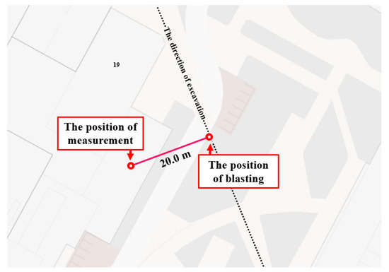
Figure 1.
Vibration measurement site position.
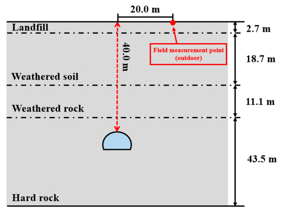
Figure 2.
Site ground layer composition.
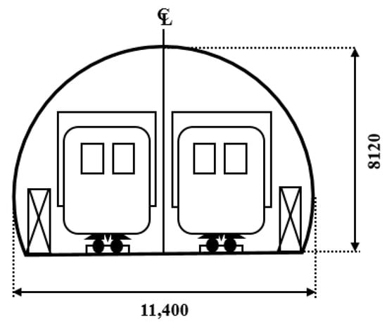
Figure 3.
Tunnel design cross-section.
3.2. Field Blasting Vibration Measurements
The equipment used for measurement has been approved by KOLAS, a Korean national certification body, and is used in many blasting sites in Korea. The measurement data comprised blasting data for a total of four days from 20 to 23 June 2022, and the vibration meter was measured every minute for 24 h. The day of blasting at the closest offset to the measurement point was the 21st. On days other than the 21st, vibrations of less than 0.1 cm/s occurred, and the maximum vibration was measured at 0.11 cm/s during blasting on the 21st (Figure 4). The measured result values were less than 0.2 cm/s, which corresponds to the domestic standard for cultural assets and vibration-sensitive structures, and vibration was not felt at the time of measurement (MOLIT, 2016). Table 1 shows domestic and foreign vibration regulation values.
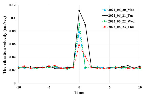
Figure 4.
Blasting vibration field measurements.

Table 1.
The blasting vibration standards for each country [20].
4. Numerical Analysis According to Tunnel Depth
Numerical analysis is becoming an increasingly important aspect of solving geotechnical problems, both quantitatively and qualitatively. Since numerical analysis is the most flexible type of ground analysis applicable to changing properties, various initial conditions, and complex boundary conditions, it has been employed widely, introducing significant changes to ground analysis and design methods. Additionally, numerical analysis can obtain results in various forms using coded computer programs [21]. To this end, we used the FLAC 3D numerical analysis program (explicit continuum modelling of nonlinear material behaviour in 3D), a widely verified program developed by ITASCA as a 3D continuum analysis program for the mechanical analysis of rocks, soil, and structures. FLAC 3D is a program with strengths in dynamic analysis based on time-domain analysis techniques as well as continuum analysis, discontinuity analysis, and mechanical-hydraulic coupling analysis considering fluid flow [22]. However, this program is difficult to simulate the shaft or the detailed conditions of TBM. In addition, it is not suitable for analysing the interaction of soil and surrounding structures. For interaction with additional surrounding structures, FEM (Finite Element Method) is recommended.
4.1. Analysis Conditions
4.1.1. Modelling and Applied Material Properties
The target ground was modelled under the same stratum conditions as shown in Figure 2, and the ground of the GTX-A construction site, which comprised landfill, weathered soil, weathered rock, and hard rock layers, was modelled. In the previous numerical analysis, the boundary conditions of the X direction (both sides), Y direction (excavation direction), and Z direction (lower surface of ground modelling) of the model were set as quiet boundaries in the FLAC 3D program, so that the reflection wave in all directions were ineffective. For the blasting load, as shown in Figure 5, the same blasting pattern and blasting load as in the actual site were applied when the TBM and NATM parallel construction method was not used. The charge hole in the centre is perforated as shown in Figure 5. The number 1 and 2 in the figure mean different amounts of charge (A = 2.20 kg, B = 2.80 kg). Based on this, in order to compare the TBM and NATM parallel construction method and the use of protective shields, the NATM top surface excavation was simulated as shown in Figure 6. At this stage, the blasting pattern and blasting load were the same as those at the site, and only the size of the NATM tunnel was modelled according to the TBM and NATM parallel construction method. When the TBM and NATM parallel construction method was used, vibration-controlled blasting was considered, since the target ground is an urban area. Due to the condition of the TBM and NATM parallel construction method, expansion blasting was modelled with only outer shell holes excluding centre-cut blasting holes. The cross-section of the tunnel widened by NATM expansion blasting was 10.0 m, and the size of the pilot tunnel pre-excavated by TBM was 5.0 m (Figure 7). The mesh of each analysis used an automatically generated mesh by FLAC 3D. In this analysis, the ground and TBM material properties were calculated by referring to the GTX-A route ground survey report, and the ground and TBM were modelled using Mohr-Coulomb and elastic models, respectively. The applied material properties are listed in Table 2.
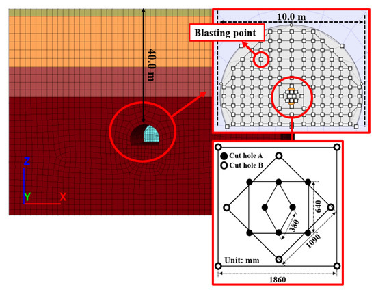
Figure 5.
Numerical modelling equivalent to field conditions.
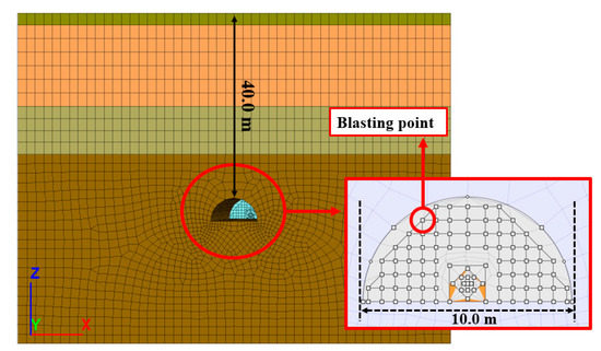
Figure 6.
Top surface excavation numerical analysis modelling based on field conditions.
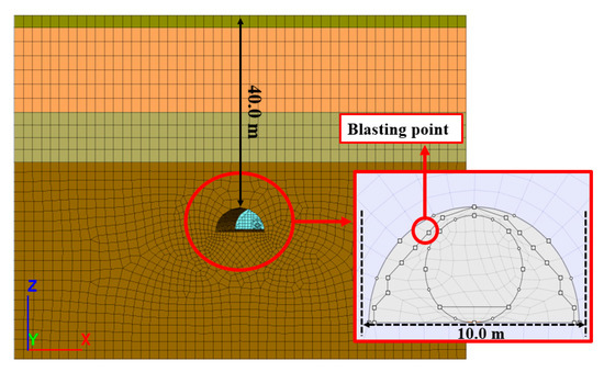
Figure 7.
Numerical analysis modelling of top surface excavation using TBM and NATM parallel construction method.

Table 2.
Ground and TBM material properties.
4.1.2. Blasting Load Calculation
In order to calculate the blasting load, the formula proposed in [23] was used. The blasting load calculated by the formula in [23] was obtained for the tamping with the charge amount for each charge hole (centre cut hole A: 2.20 kg, centre cut hole B: 2.80 kg, expanded hole: 0.75 kg), and the proposed formula in [24] was used to calculate the equivalent blasting load (P’). In this study, only the tamping was calculated here to interpret the same as the field conditions. For application as a dynamic load, the time history of vibration generated by blasting must be considered as well. As for the blasting load time history, the hysteresis curve of [24] was mainly used, and the calculated time history curve is shown in Figure 8. In this analysis, the equivalent blasting loads for the charge holes (centre cut hole A, centre cut hole B, and expanded hole) were calculated as 150.58 kg/cm2, 191.65 kg/cm2, and 119.78 kg/cm2, respectively [25]. The actual ground damping is not affected by the vibration frequency, but the damping matrix in the nonlinear analysis performed in the time domain is greatly affected by the frequency [26]. Moreover, according to the study of [27], as the damping increases, the conversion distance increases and the PPV decreases rapidly. Therefore, calculations about frequency and damping ratio are important. In this study, referring to [27], the duration was set as 0.001 s, and the equivalent frequency and ground damping ratio were 830 Hz and 1.0%, respectively. The equation for the blasting load calculation is Equations (1)~(5).
where PD: Blasting load (kg cm−2); Ve: Average explosion velocity (m s−1); ρe: Average density (g cm−3).
where ρa: Dielectric flux density of sand (g cm−2); Ca: Propagation velocity of shockwaves (sand) (m s−1)
where de: Explosive diameter (mm); dh: Borehole (mm)
where W: Charge per delay (kg)
where P(t): Pressure at time t (kg cm−2); B: Load constant (16,338); t: Arrival time (0.06 μs).
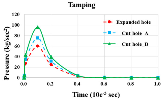
Figure 8.
Time history curve.
4.1.3. Analysis Case and Measurement Position
Analysis was performed under the same conditions as the site at a tunnel depth of 40.0 m, and compared with the field vibration measurement data. For the case of NATM half section (top) excavation and that using TBM and NATM parallel construction method, analyses were performed according to the depth, as shown in Figure 9. The measurement position on the ground surface for comparison with field data is shown in Figure 10. For the TBM and NATM parallel construction method, the impact of vibration according to the depth was analysed by measuring at the top of the pilot tunnel, the TBM, and the TBM excavation surface.
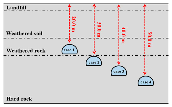
Figure 9.
Numerical analysis cases by depth.
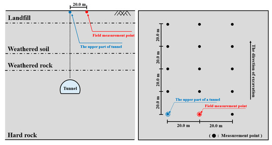
Figure 10.
Blasting vibration measurement position.
4.2. Analysis Results
4.2.1. Comparison of Field Measurement Data and Numerical Analysis Results
The field measurement data were 0.11 cm/s, and the measurement equipment that meets the Korean national standards was used. The result value was measured 20.0 m horizontally from the aboveground part of the tunnel under the same conditions of ground, blasting, and depth (40.0 m), as shown in Figure 11. The result measured 20.0 m horizontally from the aboveground part of the tunnel did not exceed 0.2 cm/s, which is the domestic standard for cultural assets and vibration-sensitive structures, listed in Table 1. In addition, as the offset from the excavation direction increased, the vibration velocity decreased rapidly, and at an offset of 80.0 m, the difference in horizontal offset seemed to be insignificant. Figure 12 shows a linear function graph of the offset in the excavation direction including the same point as the field data measurement position. This graph shows an accuracy of 98.89%, and the maximum vibration velocity for each offset can be interpreted using this graph.
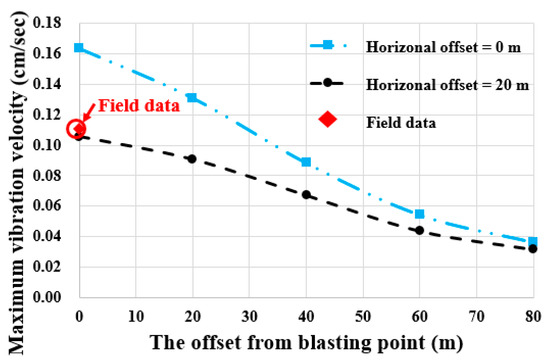
Figure 11.
Comparison of field measurement data and numerical analysis results.
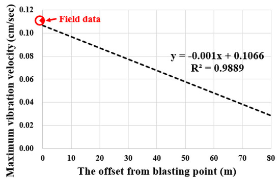
Figure 12.
Vibration prediction linear function graph according to offset in excavation direction.
4.2.2. Numerical Analysis Results According to Tunnel Depth
In this analysis, the case of general blasting with the same ground and blasting conditions as the previous field test and the case of using TBM and NATM parallel construction method with the protective shield were compared in terms of the tunnel depth. Here, the blasting surface was modelled as a half section (upper half blasting), as shown in Figure 6 and Figure 7, due to the characteristics of the TBM and NATM parallel construction method. Further, in the case of the TBM and NATM parallel construction method, the blasting hole was simulated with a contour hole. The position where the vibration measurement was conducted was measured at intervals of 20.0 m in the excavation direction with respect to the same measurement position (horizontal offset = 20.0 m) as the site directly above the tunnel. Figure 13 shows the results measured at each tunnel depth (20.0 m, 30.0 m, 40.0 m, and 50.0 m). When using the TBM and NATM parallel construction method with the protective shield at a tunnel depth of 20.0 m, there was a maximum vibration reduction effect of 53.85% directly above the blasting surface. Additionally, the vibration was reduced by up to 75.23% at a point 20.0 m away horizontally, which is the same point as the field measurement point. This trend showed a larger decrease rate as the tunnel excavation depth increased, where 72.50% (30.0 m depth), 75.74% (40.0 m depth), and 79.67% (50.0 m depth) decrease were observed directly above the surface; and 79.16% (30.0 m depth), 81.81% (40.0 m depth), and 83.33% (50.0 m depth) decrease were observed at a point 20.0 m away horizontally (Figure 14). As a result, it was confirmed that there is a vibration reduction effect when using the NATM parallel construction method with the protective shield, and the reduction effect is expected to increase as the tunnel excavation depth deepens.
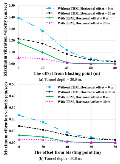
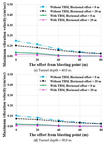
Figure 13.
Comparison of vibration reduction for offset in excavation direction.
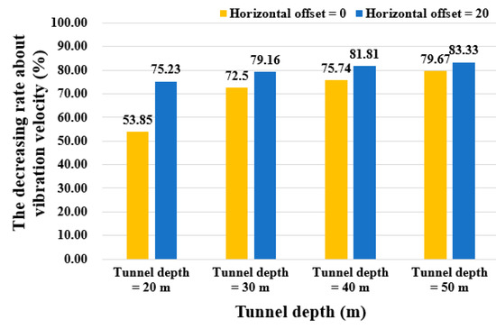
Figure 14.
Vibration velocity reduction in the TBM and NATM parallel construction method by tunnel depth.
5. Numerical Analysis According to Tunnel Size
5.1. Analysis Conditions
As shown in Figure 2, the target ground comprised landfill, weathered soil, weathered rock, and hard rock layers, and the material properties of each stratum are listed in Table 2. For numerical analysis, each case was classified into a total of six types according to the NATM widening tunnel size and TBM pre-excavation tunnel size, as shown in Figure 15. In the TBM and NATM parallel construction method, only the outer shell hole was blasted, and the same load as that of the expanded hole described in Section 4.1.2 was applied. The blasting vibration measurement position was measured at the rear of the TBM device at the top of the pilot tunnel and at the TBM excavation surface. The measurement points are shown in Figure 16.
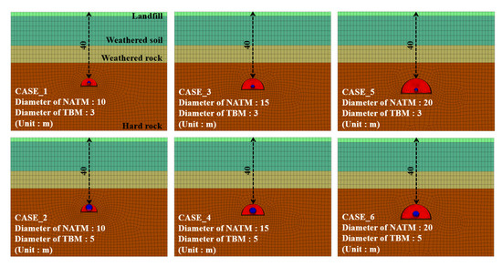
Figure 15.
Cases of analytical modelling according to size of NATM tunnel and TBM pre-excavation tunnel.
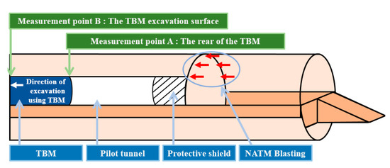
Figure 16.
Measurement point.
5.2. Numerical Analysis Results by Tunnel Size
Figure 17 shows the vibration reduction effect according to the size of the pilot tunnel for each cross-sectional area of the back expansion blasting. The cross-sectional diameters of the NATM expansion blasting were classified into 10.0 m, 15.0 m, and 20.0 m, and at this time, the vibration velocity was measured for the pilot tunnel diameters of 3.0 m and 5.0 m for each cross-sectional diameter. Figure 17a,b shows the results of vibration velocity measurement at the rear of the TBM and at the excavation surface of the TBM when the expansion blasting cross section is 10.0 m and the pilot tunnel size is 3.0 m and 5.0 m. As the size of the pilot tunnel increased from 3.0 m to 5.0 m, the vibration velocity measured at the rear of the TBM and the excavated surface of the TBM decreased by 22.17% and 15.55%, respectively. These results prove that as the diameter of the pilot tunnel is equal to the size of the NATM extension blasting, the vibration velocity decreased due to the securing of a free surface. In other words, as the diameter of the blasting surface and the diameter of the TBM excavation became equal, a larger free surface was secured, which decreased the vibration velocity. Figure 17c–f show the results when only the expansion blasting cross-sectional diameter increased to 15.0 m and 20.0 m, respectively, under the same conditions. Compared to the previous expansion blasting cross-sectional diameter of 10.0 m, the vibration velocity increased significantly as the NATM expansion blasting cross-sectional area increased. This may be attributed to the fact that the blasting area simulated by the outer shell hole blasting experiences an increase in the number of blasting holes as the NATM expansion blasting cross-sectional area increases. However, as the pilot tunnel diameter increased from 3.0 m to 5.0 m, the vibration velocity decreased by 33.90% and 25.70% (when the expansion blasting cross-sectional diameter was 15.0 m), and 73.02% and 69.34% (when the expansion blasting cross-sectional diameter was 20.0 m) at the rear and the excavation surface of the TBM, respectively. From these results, it can be inferred that the larger the expansion blasting cross-sectional diameter, the greater the vibration velocity reduction effect due to the securing of a free surface. In summary, the vibration velocity decreases as the expansion blasting cross-sectional diameter and the cross-sectional diameter of the pilot tunnel due to the TBM pre-excavation become equal. Thus, it can be concluded that selecting the TBM pre-excavation pilot tunnel size considering this factor is important for the stability of the TBM and the ground.
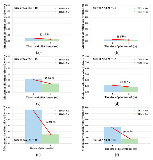
Figure 17.
Cases of analytical modelling according to size of NATM tunnel and TBM pre-excavation tunnel. (a) The rear of the TBM (NATM = 10); (b) The TBM excavation surface (NATM = 10); (c) The rear of the TBM (NATM = 15); (d) The TBM excavation surface (NATM = 15); (e) The rear of the TBM (NATM = 20); (f) The TBM excavation surface (NATM = 20).
6. Conclusions
The purpose of this study was to minimise the effect of NATM widening blasting on the pilot tunnel and TBM surroundings by using a protective shield during TBM and NATM widening parallel excavation. Accordingly, after comparing the numerical analysis results under the same conditions with the actual field measurement data, half-section blasting was modelled and compared with the results using the TBM and NATM parallel construction method. In addition, the effect according to the tunnel excavation depth and NATM and TBM excavation cross-sectional size was compared and analysed. The main results are as follows.
- Vibrations from the actual excavation were measured on the ground surface of the GTX-A construction site where tunnels were excavated only by blasting, and it was confirmed that similar results were obtained from modelling and analysis under the same conditions (the maximum vibration was measured at 0.11 cm/s). Based on this, the difference in vibration between the TBM and NATM parallel construction method using the protective shield and when the tunnel half section was excavated only by blasting excavation were compared, and the results were organised according to the tunnel excavation depth. As a result of measuring the vibration at the same point as the field measurement, when the tunnel excavation depth was 20.0 m, the vibration velocity was reduced by 75.23% by the parallel excavation method, compared to blasting excavation. Further, it was observed that the greater the depth, the greater the reduction (30.0 m depth = 79.16%, 40.0 m depth = 81.81%, 50.0 m depth = 83.33%). Therefore, it is judged that large-depth tunnel excavation has a greater vibration reduction effect than low and medium-depth tunnel excavation.
- In the case of an expansion blasting cross-section of 10.0 m, as the pilot tunnel size increased from 3.0 m to 5.0 m, the vibration velocity measured at the rear of the TBM and the excavation surface of the TBM decreased by 22.17% and 15.55%, respectively. When the expansion blasting cross section was extended to 15.0 m and 20.0 m, the vibration occurred more extensively, and as the TBM pilot tunnel size increased from 3.0 m to 5.0 m, the vibration reduction width also increased along with the expansion blasting cross-section. Due to the condition of the TBM and NATM construction method, which is blasted with an outer shell hole, it seems that the vibration velocity increases as the expansion blasting cross-section and the number of blasting holes increase. The tendency for the vibration velocity to decrease as the size of the TBM pilot tunnel increases to 3.0 m and 5.0 m is considered to be because securing a free surface has a great effect on reducing the vibration velocity.
- These results show that the vibration velocity reduction width increases as the expansion blasting cross-section increases, but when the expansion blasting cross-section is 20.0 m or more, it exceeds the maximum domestic standard of 4.0 cm/s, as well as foreign standards. Thus, actual construction is expected to be difficult. Therefore, when using the TBM and NATM parallel construction method using a protective shield, the area of the widening blasting surface should be preferably 10.0 m or less, which is measured at a vibration velocity of 1.0 cm/s. Further, considering the cost aspect, it is effective to construct the free surface as large as possible.
- This study was conducted based on the measurement data of a specific site, and further research on various ground and blasting conditions is needed. Moreover, when excavating an underground tunnel, we plan to study a method to protect the TBM backup device from blasting rockslide during the TBM and NATM parallel construction method. In addition, studies on the force (the torque, thrust force, chamber pressure, and upward force) acting on the TBM and tunnel lining, which were not considered in this study, will be added.
Author Contributions
Writing—original draft preparation and numerical analysis, S.-M.K.; resources, Y.B.; data curation, S.-I.C.; conceptualization, C.-Y.K.; writing—review and editing, S.-W.L. All authors have read and agreed to the published version of the manuscript.
Funding
This research was supported by the Korea Agency for Infrastructure Technology Advancement (KAIA). (Project: Research of Advanced Technology for Construction and Operation of Underground Transportation Infrastructure, No. 22UUTI-C157788-03).
Institutional Review Board Statement
Not applicable.
Informed Consent Statement
Not applicable.
Data Availability Statement
Not applicable.
Conflicts of Interest
The authors declare no conflict of interest.
References
- Lee, I.M. Principles of Rock Mechanics; CIR: Seoul, Republic of Korea, 2004. [Google Scholar]
- Kong, S.M.; Kim, A.R.; Byun, Y.S.; Shim, S.B.; Choi, S.I.; Lee, S.W. Analysis of stability and required offset with vibration velocity considering conditions of bedrock and explosive charges using the TBM and NATM extension blasting method. Appl. Sci. 2022, 12, 3473. [Google Scholar] [CrossRef]
- Kim, Y.K.; Lee, J.K.; Lee, S.S. A fundamental study on the automation of tunnel blasting design using a machine learning model. Tunn. Undergr. Space Assoc. 2022, 9, 431–449. [Google Scholar]
- Kim, Y.G. Review on underground safety management in Korea. Mag. Korean Tunn. Undergr. Space Assoc. 2020, 22, 4–19. [Google Scholar]
- Sauer, G.; Lama, R.D. An application of New Austrian Tunneling Method in difficult built over areas in Frankfurt/Main Metro. Symp. Rock Mech. Tunn. Probl. 1973, 1, 79–92. [Google Scholar]
- Kim, H.J.; Moon, H.K.; Lee, Y.J. Insights into the New Austrian tunnelling method (NATM) II. Geotech. Eng. Korean Geotech. Soc. 2010, 26, 45–51. [Google Scholar]
- Kim, M.S.; Jung, J.H.; Lee, J.K.; Park, M.S.; Park, J.H.; Lee, S.W. Development and Application of Large-diameter Cut-hole Exploration System for Assessment of the Geological Condition beyond NATM Tunnel Face. Tunn. Undergr. Space Technol. 2021, 2, 1–9. [Google Scholar]
- Lee, Y.S.; Yoon, Y.G.; Oh, T.K. A Study on Disaster Influencing Factor and Importance to Safety Management in NATM Tunnel Drilling. J. Converg. Cult. Technol. 2022, 8, 757–763. [Google Scholar]
- Beak, J.H.; Beak, S.H.; Han, D.H.; Won, A.R.; Kim, C.H. A Study on the Design of PLHBM. J. Korean Soc. Explos. Blasting Eng. 2012, 30, 66–76. [Google Scholar]
- Choi, H.B.; Han, D.H.; Ki, K.C. A Study on the Decay Effect of Ground Vibration based on the Number of PLHBM Holes in Gneiss Area. J. Korean Soc. Explos. Blasting Eng. 2016, 34, 1–9. [Google Scholar]
- Chun, B.S.; Song, S.H.; An, J.W. Ground behaviour and reinforcing method of NATM tunnel through deep weathered zone. J. Korean Geotech. Soc. 2007, 23, 87–95. [Google Scholar]
- Heo, J.; Kim, B.I.; Lee, J.D.; Kim, Y.G. 3D numerical study on the reinforcing effect of inclined system bolting in NATM tunnel. J. Korean Geotech. Soc. 2017, 33, 29–36. [Google Scholar]
- Jeon, Y.J.; Lee, C.J. A Study on the behavior of single piles to adjacent tunneling in stiff clay. J. Korean Geo-Environ. Soc. 2015, 16, 13–22. [Google Scholar] [CrossRef]
- Kim, K.Y.; Kim, J.J.; Ryu, H.W.; Rehman, H.; Jafri, T.H.; Yoo, H.K.; Ha, S.G. Estimation method for TBM cutterhead drive design based on full-scale tunneling tests for application in utility tunnels. Appl. Sci. 2020, 10, 5187. [Google Scholar] [CrossRef]
- Choi, S.W.; Lee, H.B.; Choi, H.S.; Chang, S.H.; Kang, T.H.; Lee, C.H. Numerical Evaluation of Forces on TBM during Excavation in Mixed Ground Condition by Coupled DEM-FDM. Tunn. Undergr. Space Technol. 2021, 31, 549–560. [Google Scholar]
- Kwon, K.B.; Choi, H.S.; Oh, J.Y.; Kim, D.K. A study on EPB shield TBM face pressure prediction using machine learning algorithms. Tunn. Undergr. Space Technol. 2022, 24, 217–230. [Google Scholar]
- Ceppi, G.; De Paoli, B.; Lotti, A.; Pedemonte, S. La galleria di Monte Olimpino 2: Scavo con tecniche special. In Proceedings of the International Congress on Large Underground Openings, Florence, Italy, 8–12 June 1986; Volume 1, pp. 127–136. [Google Scholar]
- Pelizza, S. Pilot bore excavation with TBM for the design and construction of larger tunnels. Tunn. Undergr. Space Technol. 1991, 6, 185–189. [Google Scholar] [CrossRef]
- Kim, M.S.; Lee, S.S. Design Study of Steel Fibre Reinforced Concrete Shaft Lining for Swelling Ground in Toronto, Canada. Appl. Sci. 2021, 11, 3490. [Google Scholar] [CrossRef]
- MOLIT. Tunnel Standard Specification; Ministry of Land, Infrastructure and Transport: Seoul, Republic of Korea, 1999; p. 1.
- Shin, J.H. Geomechanics & Engineering 2; CIR: Seoul, Republic of Korea, 2015. [Google Scholar]
- Itasca Consulting Group Inc. FLAC 3D 6.0 Manual: Examples (An Excerpt from FLAC3D Help); Itasca Consulting Group Inc.: St. Paul, MN, USA, 2017; pp. 39–52. [Google Scholar]
- Hino, K. Theory and Practice of Blasting; Nippon Kayaku Co., Ltd.: Tokyo, Japan, 1959. [Google Scholar]
- Starfield, A.M.; Pugliese, J.M. Compression waves generated in rock by cylindrical explosive charges: A comparison between a computer model and field measurements. Int. J. Rock Mech. Min. Sci. Geomech. Abstr. 1968, 5, 65–77. [Google Scholar] [CrossRef]
- Jeon, S.S.; Cho, B.S.; Kim, D.S.; Jang, Y.W. Evaluation of the tunnel stability induced by Bla st Loading. In Proceedings of the Korean Society of Civil Engineers 2006 Convention Conference and Civil Expo, Seoul, Republic of Korea, 30 May–3 June 2006; pp. 4306–4309. [Google Scholar]
- Park, D.; Kim, T.G.; Ahn, J.K.; Park, I.J. Amplification characteristics of mountain slope. J. Korean Soc. Hazard Mitig. 2013, 13, 117–123. [Google Scholar]
- Ahn, J.K.; Park, D.H.; Shin, Y.W.; Park, I.J. Generation of blast load time series under tunneling. J. Korean Tunn. Undergr. Space Assoc. 2014, 16, 51–61. [Google Scholar] [CrossRef]
Disclaimer/Publisher’s Note: The statements, opinions and data contained in all publications are solely those of the individual author(s) and contributor(s) and not of MDPI and/or the editor(s). MDPI and/or the editor(s) disclaim responsibility for any injury to people or property resulting from any ideas, methods, instructions or products referred to in the content. |
© 2023 by the authors. Licensee MDPI, Basel, Switzerland. This article is an open access article distributed under the terms and conditions of the Creative Commons Attribution (CC BY) license (https://creativecommons.org/licenses/by/4.0/).