Article

Multi-Information Fusion Indoor Localization Using Smartphones

1
Guangxi Key Laboratory of Precision Navigation Technology and Application, Guilin University of Electronic Technology, Guilin 541004, China
2
School of Information and Communication, Guilin University of Electronic Technology, Guilin 541004, China
3
Guangxi Key Laboratory of Image and Graphic Intelligent Processing, Guilin University of Electronic Technology, Guilin 541004, China
4
National and Local Joint Engineering Research Center of Satellite Navigation Positioning and Location Service, Guilin 541004, China
5
GUET-Nanning E-Tech Research Institute Co., Ltd., Nanning 530000, China
6
Department of Science and Engineering, Guilin University, Guilin 541004, China
*
Authors to whom correspondence should be addressed.
Appl. Sci. 2023, 13(5), 3270; https://doi.org/10.3390/app13053270
Submission received: 25 January 2023 / Revised: 27 February 2023 / Accepted: 28 February 2023 / Published: 3 March 2023

Abstract

:
Accurate indoor localization estimation has important social and commercial values, such as indoor location services and pedestrian retention times. Acoustic-based methods can achieve high localization accuracies in specific scenarios with special equipment; however, it is a challenge to obtain accurate localization with general equipment in indoor environments. To solve this problem, we propose a novel fusion CHAN and the improved pedestrian dead reckoning (PDR) indoor localization system (CHAN-IPDR-ILS). In this system, we propose a step length estimation method that adds the previous two steps for extracting more accurate information to estimate the current step length. The maximum influence factor is set for the previous two steps to ensure the importance of the current step length. We also propose a heading direction correction method to mitigate the errors in sensor data. Finally, pedestrian localization is achieved using a motion model with acoustic estimation and dynamic improved PDR estimation. In the fusion localization, the threshold and confidence level of the distance between estimation base-acoustic and improved PDR estimation are set to mitigate accidental and cumulative errors. The experiments were performed at trial sites with different users, devices, and scenarios, and experimental results demonstrate that the proposed method can achieve a higher accuracy compared with the state-of-the-art methods. The proposed fusion localization system manages equipment heterogeneity and provides generality and flexibility with different devices and scenarios at a low cost.

1. Introduction

Location-based services (LBS) have received increasing attention, have many market application scenarios, and have social and commercial values due to the rapid growth of wireless technology and social requirements. Example applications include smart homes; currently widely important epidemic prevention and treatment; car searching in underground garages; underwater target detection and tracking; store positioning in shopping malls; etc. [1]. Although the global navigation satellite system (GNSS) can meet all weather-positioning requirements in outdoor environments, it is difficult to meet requirements in indoor environments due to weak signals that are blocked by buildings. Indoor localization has thus become a challenging and hot research topic in recent years.
Researchers have conducted a series of studies on ultra-wideband (UWB) [2,3,4] positioning, WIFI positioning [5,6], infrared positioning [7], radio frequency identification (RFID) positioning [8,9,10,11,12], Bluetooth positioning [13,14], geomagnetic positioning [15,16], visual positioning [17], and ultrasonic positioning [18,19]. The indoor positioning method based on ultrawideband can achieve high positioning accuracy and good stability. The literature [20] proposed a new collaborative pedestrian synchronous localization and mapping algorithm but requires special infrastructure. The approach, based on infrared technology, requires a lot of power and is blocked by indoor walls or obstacles; therefore, it is used only in some special scenarios [21]. The approaches based on Wi-Fi and Bluetooth are low-cost and easy to promote; however, data acquisition typically requires a long time [18]. The indoor localization method based on RFID achieves high accuracies but has additional infrastructure costs [10,11,12,22]. Geomagnetic sequences are strongly affected by surrounding ferromagnetic materials, making it difficult to establish a fingerprint database with huge human power and update it occasionally [23]. Vision-based positioning has good visibility [24]; however, localization performance is limited by light conditions and cannot be permitted in numerous situations because of privacy and security issues.
Of all localization signals, the ultrasonic signal is compatible with mobile equipment, and the data transmission and reception can be obtained using only mobile equipment. Ultrasonic-based localization has good adaptability for scenes without additional infrastructure and high adaptability, and sufficient accuracy for low propagation speed. Localization is achieved by time correlations with low computational complexities, making the localization approach based on ultrasound one of the most competitive indoor localization technologies [1,10,11,12]. However, due to reflection, refraction, obstruction, and the interference of other frequency signals when the acoustic signal propagates indoors, accidental errors will occur in the localization process and result in the deterioration of the localization accuracy in some cases [25].
Pedestrian dead reckoning (PDR) is a localization method that estimates a user’s location according to the user’s walking characteristics. In addition, the pedestrian motion information is captured by motion sensors such as accelerometers, gyroscopes, and magnetometers installed in smartphones. Pedestrian dead reckoning achieves good localization accuracy in a short time, which is suitable for the real-time localization tracking of fast-moving users. However, the PDR algorithm relies on other positioning techniques to provide an accurate initial location, and there are cumulative positioning errors for long-term localization. Therefore, PDR technology is generally integrated with other indoor localization technologies [26].
Overall, it is difficult to trade off compatibility, cost, and accuracy for indoor localization. Most current localization systems are infrastructure-based, which makes them impossible to implement on a large-scale application. More efforts must be made to determine how to achieve localization accuracy, compatibility with smartphones, cost, and real-time performance in indoor localization systems. These issues also create more challenges with regard to positioning, which can be summarized as follows:
  • How can the tradeoff of cost and precision be mitigated in indoor environments? High precision often requires high costs, but in real applications users typically hope to achieve high precision performance at low cost. Therefore, low cost and high precision are the core key research topics in localization.
  • How can heterogeneous equipment be achieved? The application scope of indoor localization is related to the requirements for device heterogeneity. A good method must be developed for different devices. Therefore, device heterogeneity remains a great challenge.
  • How can the generality of indoor localization be achieved? Both environments and human behaviors have a strong influence on positioning. Therefore, eliminating this interference remains a challenge for localization.
In localization methods, research has focused on scene analysis algorithms and triangulation algorithms. Scene analysis algorithms include the offline stage and online stage. In the offline stage, a fingerprint database is constructed in the whole scene in advance. In the online stage, localization is achieved to find the location of the maximum probability by matching the fingerprint database. Aqilah Binti Mazlan et al. [27,28] proposed KD-CNN-IPS and TAKD-CNN-IPS to achieve good performance, respectively. However, the fingerprint database needs to update once the scene changes, it requires large manpower. The triangulation algorithm includes the time of arrival (ToA) [29,30], angle of arrival (AoA) [31,32], and time difference of arrival (TDoA) [33,34]. The time of arrival requires accurate timing synchronization at the beacons and the target; it brings a great challenge for the high-cost and real-time localization performance. The angle of arrival estimation is achieved through the angles at which the signal arrives from the target to the beacons; it requires large antenna arrays and has a high-cost [10,11,12]. The time difference of arrival estimates the time differences at the beacons; the target location is the intersection of many hyperbolic curves from the time differences. It has low calculation complexity and low cost; no time synchronization is required. Among TDOA-based location algorithms, the CHAN algorithm [35,36] does not need an initial value and can reach the lower limit of Cramero.
To address these challenges, we propose a low-cost and high-precision indoor pedestrian tracking method based on the compatibility of ultrasonic signals and smartphones. In this method, we fuse the localization approach based on ultrasonic signals and the improved PDR method. Data transmission and reception are achieved using smartphones, and ultrasonic localization is implemented using the CHAN algorithm. The proposed method mitigates the accidental errors in ultrasonic localization and the cumulative errors of PDR. The primary contributions of study paper are as follows:
  • A dynamic improved PDR method. In this article, we propose a dynamic improved PDR method. In this method, we add the previous two steps to estimate the current step length. We also introduce a compensation factor due to some errors from the sensors themselves when collecting sensor data. The maximum influence factor is set for the previous two steps to ensure the importance of the step length estimation at the current time. The experiments show that the proposed method can provide more location information and achieve better performance than the traditional method.
  • An error correction method for heading direction. During improved PDR estimation, to mitigate equipment heterogeneity, we propose a heading direction correction method. The experimental results demonstrate that issues of equipment heterogeneity have been solved.
  • Fusion localization framework-based acoustic signal. Considering compatibility with ultrasonic signals, we propose a fusion CHAN and the improved PDR indoor localization system (CHAN-IPDR-ILS). We developed some experiments with different devices and pedestrians at the two sites. The experimental results demonstrate that the fusion localization system can achieve comparable performance, generality, and flexibility for application.
The remainder of this paper is organized as follows: Section 2 describes the related work. Section 3 presents the workflow of the proposed localization system. Section 4 describes the localization architecture. Section 5 provides experimental verification and analysis. Section 6 summarizes the results of this paper.

2. Related Work

Indoor localization technology has been widely researched for decades. Relevant research at home and abroad can be divided into the following two categories. First, indoor positioning technology is based on wireless networks, such as ultrasonic [18,19], ultrawideband [4,37], Bluetooth [13,38,39], and Wi-Fi [6,40]. The second category includes indoor positioning technology based on inertial devices, pedestrian inertial navigation systems (PINS), and PDR.
The localization approach ultrasonic-base promotes the development of positioning technology due to its compatibility with smartphones. Liu, K. [41] first proposed the GuoGuo positioning system with a smartphone, in which an acoustic signal between 15 and 20 kHz is used and achieves 6–25 cm positioning performance. Luo, X. et al. [42] proposed a new ultrasonic positioning method based on the receiver array optimization scheme, which can effectively improve the accuracy of indoor positioning. The literature [43] analyzed the localization effect of the CHAN and Taylor algorithms and demonstrated that the CHAN algorithm achieves better localization than the Taylor algorithm. The acoustic signal is susceptible to environmental interference, and accidental errors inevitably affect the localization performance.
Pedestrian location in PDR estimation can be determined via step accumulation during walking. The literature [14] proposed the BtPDR localization method, which integrated the PDR method with Bluetooth. The localization accuracy is improved by 42.6% compared with the traditional PDR method. Lee, Gang Toe et al. [44] proposed an indoor localization method that combined the UWB method with the PDR method. The proposed fusion algorithm improved the localization accuracy and solved the errors for non-line-of-sight environments in the UWB estimation. The literature [45,46] proposed the fuse localization method, which combines ultrasonic signals with PDR estimation and achieved high-precision performance in the indoor environment. The literature [47,48] proposed an indoor positioning method based on the Wi-Fi, Bluetooth, and PDR methods. The fusion method solved the Wi-Fi signal instability and cumulative error in PDR localization.
In research, many achievements in indoor localization have been made. However, low cost, high accuracy, and compatibility with different smartphones cannot be uniformly satisfied in different scenarios with the existing methods. Thus, inspired by existing localization technologies, we propose a fusion localization method that combines the CHAN algorithm and the improved PDR algorithm. The experiments demonstrate that the proposed method can solve abnormal points in acoustic signal localization, and effectively alleviate cumulative errors over time caused by the PDR algorithm. Also, the proposed method can use different scenes and different devices.

3. System Workflow

In this part, the overall scheme of the multi-information localization system is presented, as shown in Figure 1.
In this scheme, the acoustic signal and inertial measurement unit (IMU) data are first captured by a smartphone. We recruited volunteers to collect data with different equipment and scenes. The volunteers held smartphones that were preinstalled with the client application and were asked to move at a constant speed. These collected data are automatically saved as formatted *.txt and sent to the server intermission. In the location solution terminal, the target location estimation acoustic base was determined using the CHAN method, and in the inertial measurement unit-based localization, the data from acceleration, gyroscope, and magnetometer were extracted from the server and preprocessed. Afterward, a dynamic improved PDR method was used to determine the pedestrians’ locations. Finally, localization was achieved via the motion model with CHAN estimation and dynamic improved PDR estimation.

4. Fusion Localization Architecture

We introduce the multi-information localization overview in Section 4.1. After that, the acoustic approach based on the CHAN algorithm is demonstrated in Section 4.2. In Section 4.3, step-counting detection is introduced and the improved adaptive step length estimation is described in Section 4.4. Heading direction estimation is illustrated in Section 4.5. Finally, the fusion localization is presented in Section 4.6.

4.1. Overview

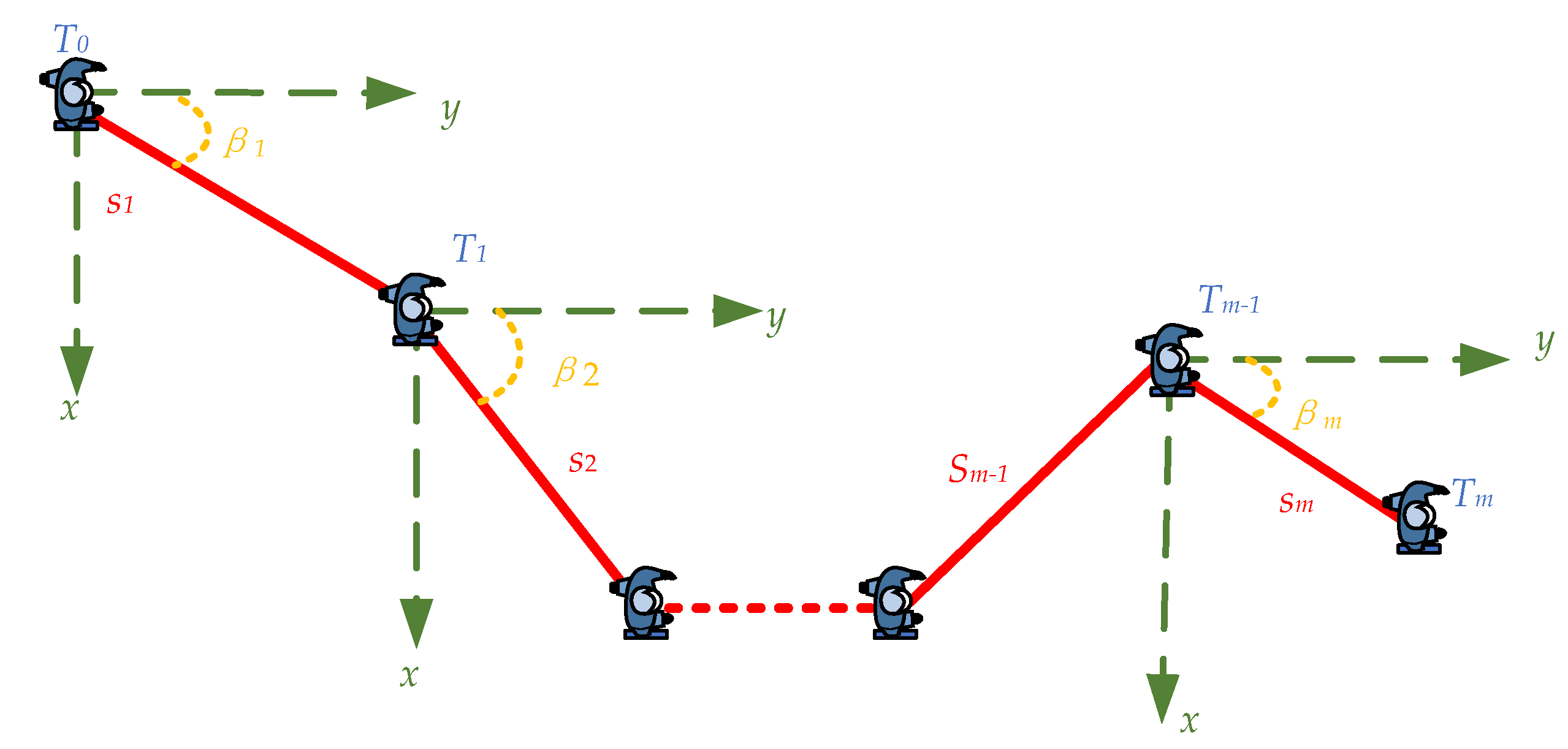
In this section, we show how the multi-information localization system operates. The motion model diagram of the target in the localization system is shown in Figure 2, which considers only the two dimensions. Therefore, the motion equation is expressed as follows:
x m y m = x m 1 y m 1 + s m s i n β m c o s β m
β m = β m e a s + β d h + β s t a t i c
where x m ,   y m and x m 1 , y m 1 denote the location of the pedestrian at times m and m − 1, s m is the step length of the m-th step, and β m denotes the heading direction of the m-th step after correction. β m e a s is the data measured by the smartphone, β d h is the correction angle for different devices, and β s t a t i c is the compensation error measured when the smartphone is stationary.
The pedestrian location can be deduced using (1) and (2). The localization is built on an improved dynamic PDR method and CHAN estimation. The dynamic PDR localization method is primarily based on the pedestrian characteristics that are achieved from the acceleration, gyroscope, and magnetometer sensors during walking. The overall localization method is depicted in Algorithm 1.
Algorithm 1: Procedure of fusion localization
Input: The acoustic signal and IMU data from smartphone.
Output: The target location U m .
1: Access data from smartphone.
2: Calculate the location U m c of the CHAN estimation as Section 4.2.
3: Peak and valley detection as Section 4.3.
4: Threshold judgment as Section 4.3.
5: Time interval detection as Section 4.3.
6: Estimate the step counting.
7: for each step do
8:   Estimate the step length s m as Section 4.4.
9:   Calculate heading direction estimation β as Section 4.5.
10:    Calculate the location U m p of the PDR estimation at time m.
11: end for
12: The fusion localization as Section 4.6.
13: If the CHAN estimation > threshold then
14:   Discard the CHAN estimation, the location at time m − 1 is U m 1 .
15:  else
16:   The location at time m − 1 is U m 1 c .
17: end if
18: Location determination and heading by motion model as (26).
19: Return step 2.

4.2. Location Initialization

The transmission and reception of acoustic signals is achieved by chirp modulation. The chirp signal is a pulse compression signal, which has good autocorrelation characteristics and can be extracted from severe signal fading. The chirp signal is characterized as follows:
m t = e j 2 π f 0 t + 1 2 k 0 t 2 , t ϵ 0 , T
where f 0 is the initial frequency, k 0 is the modulation rate, and T is the duration time.
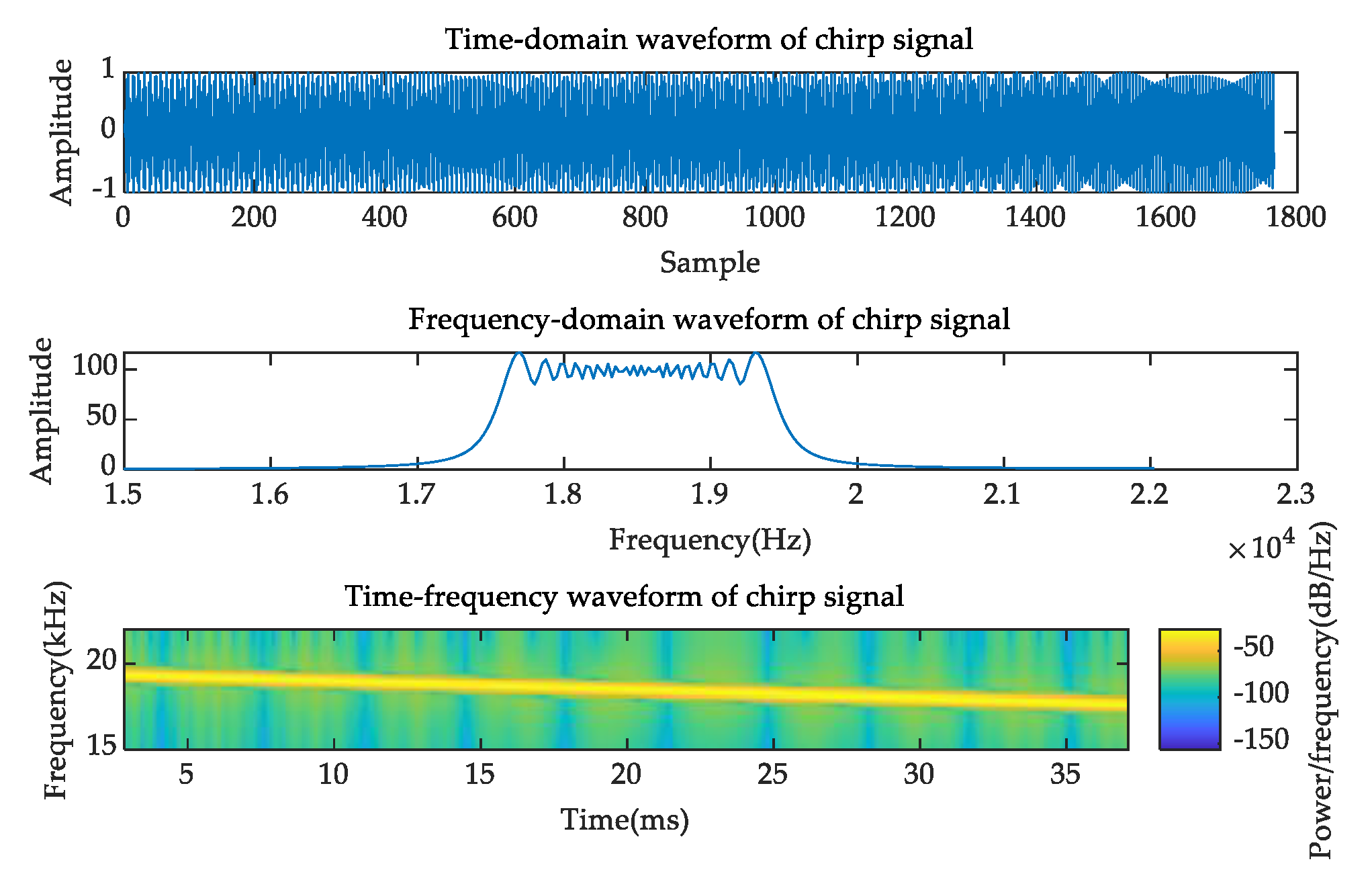
In this paper, the frequency range of the chirp signal is between 17.5 and 19.5 kHz, and 40 ms per frame is shown in Figure 3. We installed the beacons with microphones and speakers at the trial scenes. The target passively listens to the beacons and saves the messages. The server terminal calculates the target location with the CHAN algorithm. The initial location of the target is achieved by ultrasonic-base estimation.
The CHAN algorithm is a non-recursive hyperbolic solution that has high localization accuracy and low computational complexity. This algorithm can reach the lower limit of Calimero in the line-of-sight environment and has been widely used in practical engineering.
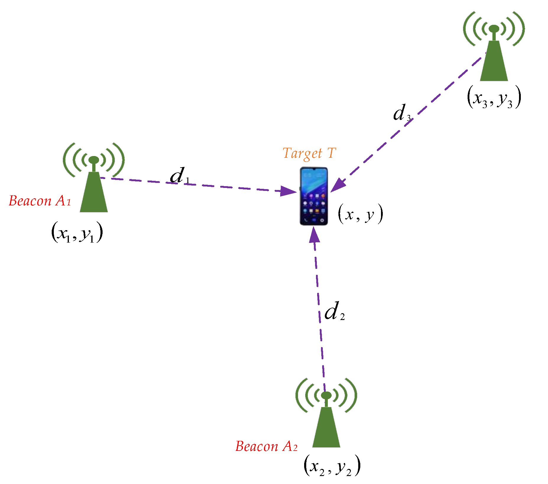
Assuming a target location T x ,   y , and beacon locations A i x i , y i ,   i = 1 ,   2 ,   3 , , the spatial position with three beacons and the target T are shown in Figure 4.
The distance difference d i 1 between the i-th beacon and the target can be calculated as follows:
x i x 2 + y i y 2 x 1 x 2 + y 1 y 2 = d i 1 ,
Expanding (4), we can obtain:
d i 1 2 + 2 d i 1 d 1 = x i 2 + y i 2 x 1 2 y 1 2 2 x x i x 1 2 y y i y 1
Assuming that r i = x i 2 + y i 2 ,   x i 1 = x i x 1 ,   y i 1 = y i y 1 , Equation (5) can be simplified as follows:
x i 1 x + y i 1 y + d i 1 d 1 = 1 2 r i r 1 d i 1 2
Equation (6) can be expressed using a matrix as follows:
h = g a F
where h = 1 2 r 2 r 1 d 21 2 r n r 1 d n 1 2 ,   g a = x 21 y 21 d 21 x n 1 y n 1 d n 1 , F = x   y   d 1 T .
Due to observation noise, the error vector can be expressed as:
e = h g a F
The covariance matrix of the error vector e is
Σ = C o v e , e = E ee T = c   2 R q R
where R = d i a g d 2 ,   d 3 , ,   d n and q is the covariance matrix.
The location estimation can be obtained through weighted least squares:
F ^ = ( g a T p g a ) 1 g a T p h
where p is the inverse of the covariance matrix Σ .
After obtaining the localization for the first time, we can obtain the equation:
e = h g a F
with the constraint:
F 1 = x 0 + 1 ; F 2 = y 0 + 2 ; F 3 = d 1 0 + 3 .
where 1 ,   2 ,   3 are the estimation F ^ . F = x x 1 2 y y 1 2 , h = F 1 x 1 2 F 2 y 1 2 F 3 2 ,   g a = 1 0 0 1 1 1 .
We obtain:
F ^ = g a T p g a 1 g a T p h
where
p = Σ 1 = 4 R C o v F R 1 ; R = d i a g x 0 x 1 , y 0 y 1 , d 1 0 c o v F = ( g a ) T p g a 1 .
The localization of the target T is
U m c = ± F + x 1 ,     y 1 T

4.3. Step-Counting Detection

The peak and valley are used to calculate the pedestrian’s step counting. To guarantee the validity of these peaks and valleys, we define four thresholds A a c c p l ,   A a c c v u ,   T t i m e u ,   a n d   T t i m e l for the peak and valley determination, where A a c c p l is the lower bound of the acceleration peak value; A a c c v u is the upper bound of the acceleration valley; and T t i m e u and T t i m e l are the upper bound and lower bound of the time interval between two adjacent peak or valley values. The step-counting detection method is characterized in detail as follows:
  • Peak and Valley Detection;
    • If A m > A m 1   a n d   A m > A m + 1 , then A (m) is the peak.
    • If A m < A m 1   a n d   A m < A m + 1 , then A (m) is the valley
    • where A m ,   A m 1 ,   and   A m + 1 are the acceleration values at times m, m − 1, and m + 1, respectively.
  • Threshold Judgment:
    • All detected peaks must be greater than A a c c p l ; otherwise, they are discarded.
    • All detected valleys are less than the preset valley threshold A a c c v u ; otherwise, they are discarded.
  • Time Interval Detection:
    • If T A m T A s t e p m 1 T t i m e u , T t i m e l , then the acceleration at time m is peak or valley; otherwise, the acceleration is discarded.
The peak and valley values at time m are determined when conditions one to three are satisfied. The step counting can be obtained from the peak and valley.

4.4. Improved Adaptive Step Length Estimation

The step length estimation is the key algorithm in PDR localization. Researchers have developed multiple mathematical models to perform related research, including the Weinberg [49], Scarlet [50], and Kim models [51], which are established through the relationship between acceleration and step length during walking:
Scarlet method:
s m = K i = 1 N A i N A m v a l l e y A m p e a k A m v a l l e y
Kim method:
s m = K i = 1 N A i N 3
Weinberg method:
s m = K A m p e a k A m v a l l e y 4
where s m is the step length of the m-th step; A m p e a k and A m v a l l e y are the peak and valley values of acceleration in the m-th step, respectively; A i is the i-th acceleration value; and N is the number of accelerations.
These models have been widely used for step length estimation. However, we must extract more accurate information during high precision localization. The models cannot satisfy the requirements of application. During movement, the pedestrian state in the current time is correlated with the current and previous states. Therefore, during step length estimation, we must consider the pedestrian states at the current and previous times. Different devices also have different errors.
Inspired by the three models [50,51,52,53], we propose a nonlinear adaptive step length estimation model, which is characterized as follows:
s m = b 1 s m 2 + b 2 s m 1 + b 3 K A m p e a k A m v a l l e y 4 + B i a s + C o m p
where s m 2 ,   s m 1 are the step length of the (m − 2)-th and (m − 1)-th steps, respectively; b 1 ,   b 2 ,   b 3 is the weight vector; B i a s is the offset error, which is measured in the stationary state; and C o m p is the accelerometer compensation of different devices.
In addition, the previous two steps have some influence on the current situation during walking. However, in the step estimation, the influence factor is sometimes too large. In this paper, the maximum weight factor Bmax is set to ensure the importance of the step length in the current state. If the weight factor b 1 is greater than Bmax, we assume that the weight W is equal to the difference of the weight factor minus the maximum weight factor; thus, W = b 1 B m a x . Then, the weight vector b 1 ,   b 2 ,   b 3 updates as follows:
b 1 = B m a x b 2 = b 2 + W / 2 b 3 = b 3 + W / 2

4.5. Improved Heading Direction Estimation

Popularized smartphones are equipped with general gyroscopes, accelerometers, and magnetometers. Therefore, to obtain reliable and accurate localization, we must develop a method to extract more accurate heading direction information from the sensors.
In the traditional PDR method, the heading direction is calculated directly using the measured value from the IMU sensors. However, different smartphones produce different errors in the collected data. To address these issues, we propose a heading direction correction method:
β m = β m e a s + β d h + β s t a t i c
where we add the correction angle β d h for different devices and compensation error β s t a t i c measured when the smartphone is stationary. Therefore, the method can solve equipment heterogeneity.
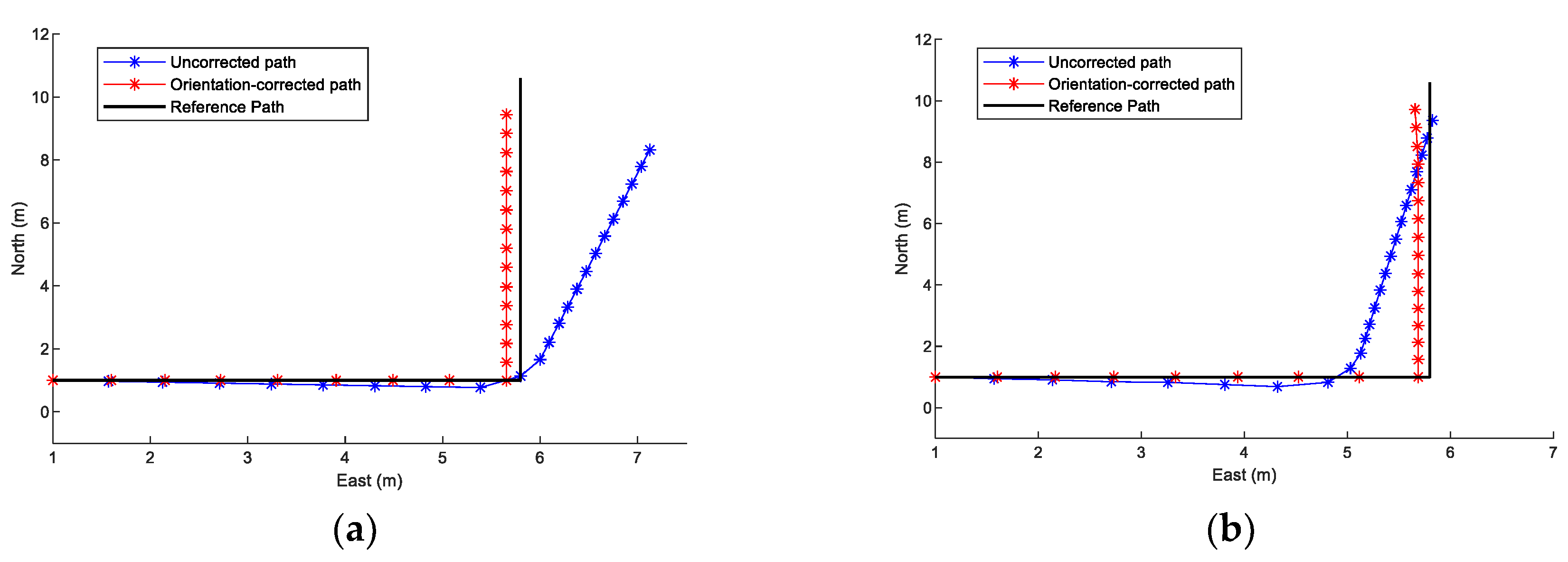
To validate the performance of the proposed method, we conducted experiments with VivoY85a and Honor60 smartphones, as shown in Figure 5. These results demonstrate that the proposed method is more accurate than the PDR method because the proposed method can extract more accurate information and effectively mitigate the errors caused by different devices.

4.6. Fusion Localization

In this part, we propose the fusion scheme to achieve better performance. In the proposed scheme, the initial location is set using CHAN estimation. We thus set a threshold D t h , where generally D t h = 2 s m 1 , to avoid outliers in localization processing.
At time m − 1, the CHAN estimation is U m 1 c x m 1 c ,   y m 1 c , and the location estimation of the proposed method is U m 1 p x m 1 p ,   y m 1 p . Two cases can occur:
Case 1: When the distance between CHAN estimation at time m – 1 and the location at m – 2 is greater than the preset threshold D t h , CHAN estimation is discarded as an outlier. Then, the location at time m – 1 is used, where x m 1 ,   y m 1 = U m 1 .
Case 2: When the distance between estimation at time m – 1 and the location at m – 2 is less than the preset threshold D t h , the location x m 1 ,   y m 1 is achieved by the distance confidence level between CHAN estimation and the proposed method U m 1 .
The distance confidence level is defined as follows:
C o n f C = 1 U m 2 U m 1 c 2
C o n f p = 1 U m 2 U m 1 p 2
The normalized distance confidence level for time m − 1 can be described by:
C o n f C = C o n f C C o n f C + C o n f p
C o n f p = C o n f p C o n f C + C o n f p
with the constraint:
C o n f p + C o n f C = 1
After determining the distance confidence level, we can obtain the location U m 1 . The localization at time m can be achieved from the following equation:
U m = U m 1 + s m s i n β m c o s β m

5. Experimental Verification and Analysis

In this section, we describe the experimental setup in Section 4.1. Then, Section 4.2 provides a discussion and analysis of the proposed method. Finally, the localization results are reported in Section 4.3.
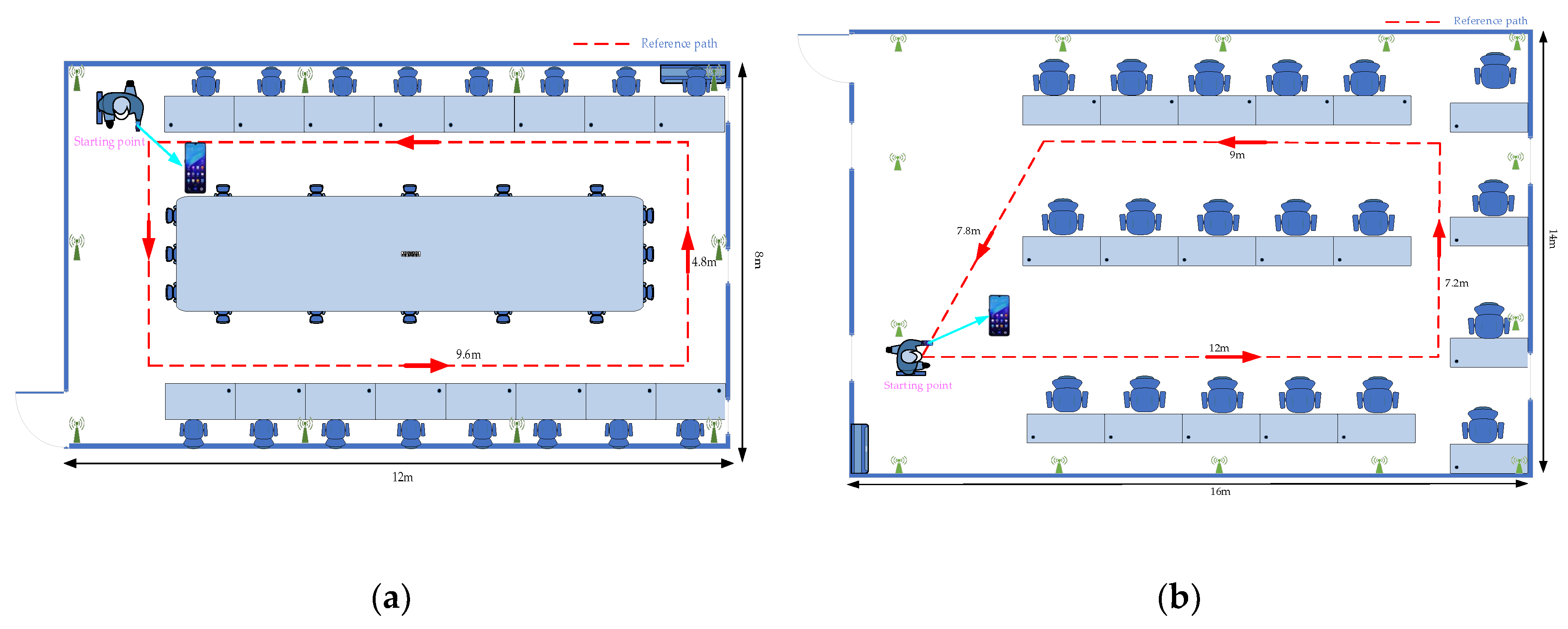
We conducted experiments at two trial sites, which included a 12 × 8 × 3 m3 area and 16 × 14 × 3 m3 area. The first scene covered approximately 96 m2 and the second scene covered approximately 224 m2. The floor plans of the experimental sites are shown in Figure 6.

5.1. Experimental Setup

We exploited the localization system based on acoustic and inertial data, which contained a client terminal and a backend server terminal.
Smartphones with IMU sensors were preinstalled in the client program. The pedestrian carried the smartphone in their hands to collect accelerometer, gyroscope, and magnetometer data as they walked along a designated route. While collecting data, time stamps and acoustic signals were collected from the beacons installed at the trial sites.
A 64-bit computer with the Windows 10 operating system operated as the server terminal. The computer with GPU GT730 and 8 GB RAM has Intel i7-7700 CPU with the frequency of 3.6 GHz. The sever terminal stored the received data and ran the localization program. Localization estimation was performed using the proposed method based on acoustic and inertial sequences.
Ten beacons in the first experimental scene and fourteen beacons in the second scene transmit ultrasonic signals periodically. The smartphone that was preinstalled with the client application was used as the target.
We recruited two volunteers to capture acoustic and IMU data who came from the local university. One female volunteer (height 155 cm, number #1) and one male volunteer (height 180 cm, number #2) each held a VivoY85a and Honor60 device to move along the survey path at each scene. At the trial scenes, we asked the volunteers to collect the data several times. The mobile phone technical information of the experiment is shown in Table 1.

5.2. Discussion and Analysis

5.2.1. Step-Counting Detection

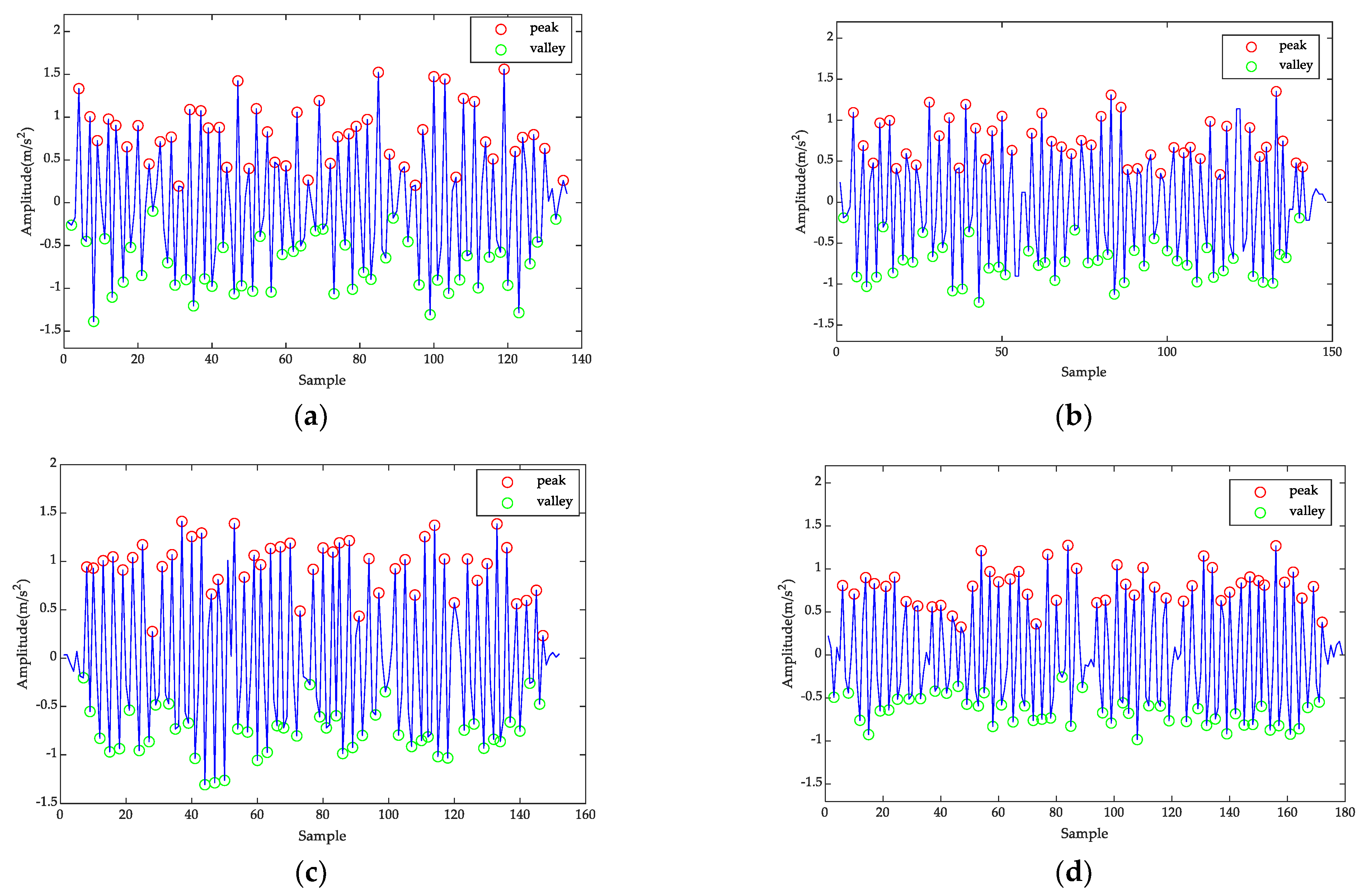
To validate the performance of step-counting estimation for different pedestrians with different devices, the two volunteers collect the acoustic signal and inertial data along each planned path at normal speed with VivoY85a and Honor60 devices. Figure 7 shows the results of the peak and valley detection for two volunteers in the first experimental scenario. The peak and valley of the pedestrian acceleration are marked with red and green circles, respectively, in the figure. Figure 7 shows that the peaks and valleys can be detected accurately for pedestrians of different heights. Figure 7a–d show that good performance is achieved when counting steps with both devices. These results are primarily achieved because the threshold can identify invalid peaks and valleys.
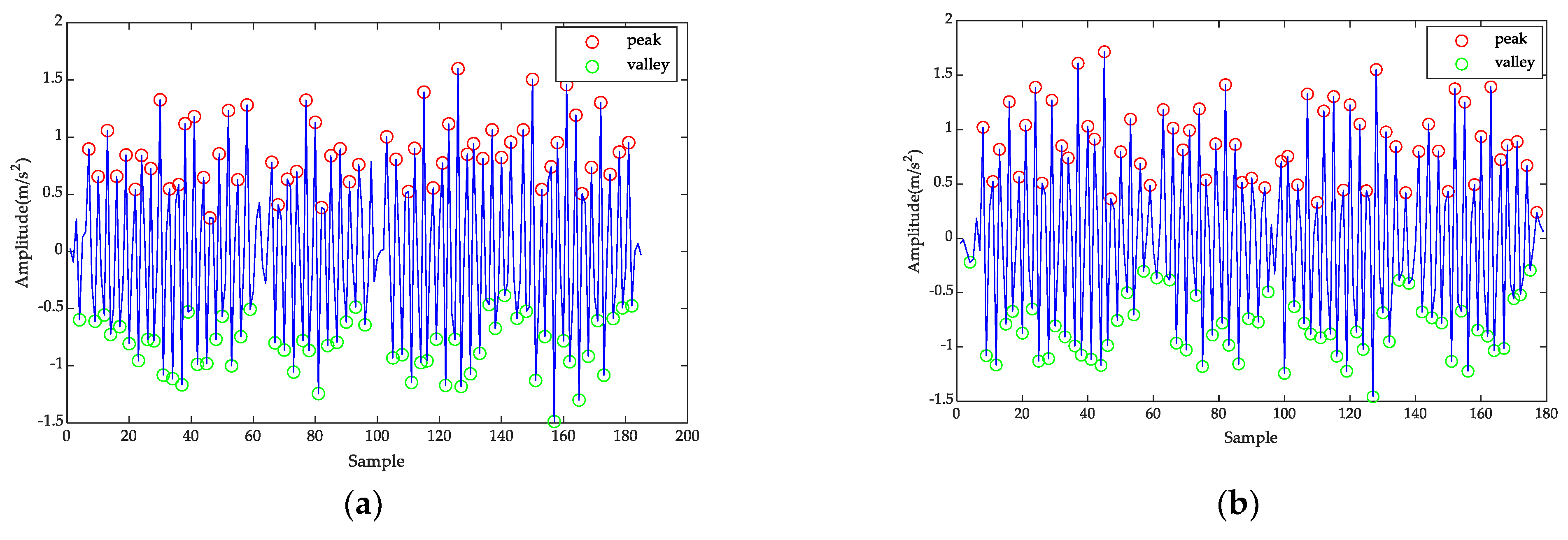
Figure 8 shows the peak and valley detection results for the two volunteers in the second scene. Peaks and valleys can be detected accurately with different devices and different heights. Once the precise peaks and valleys are obtained, steps can be counted. Therefore, step counting achieves good performance with different devices in different scenes and good universality without device heterogeneity.

5.2.2. Step Length Estimation

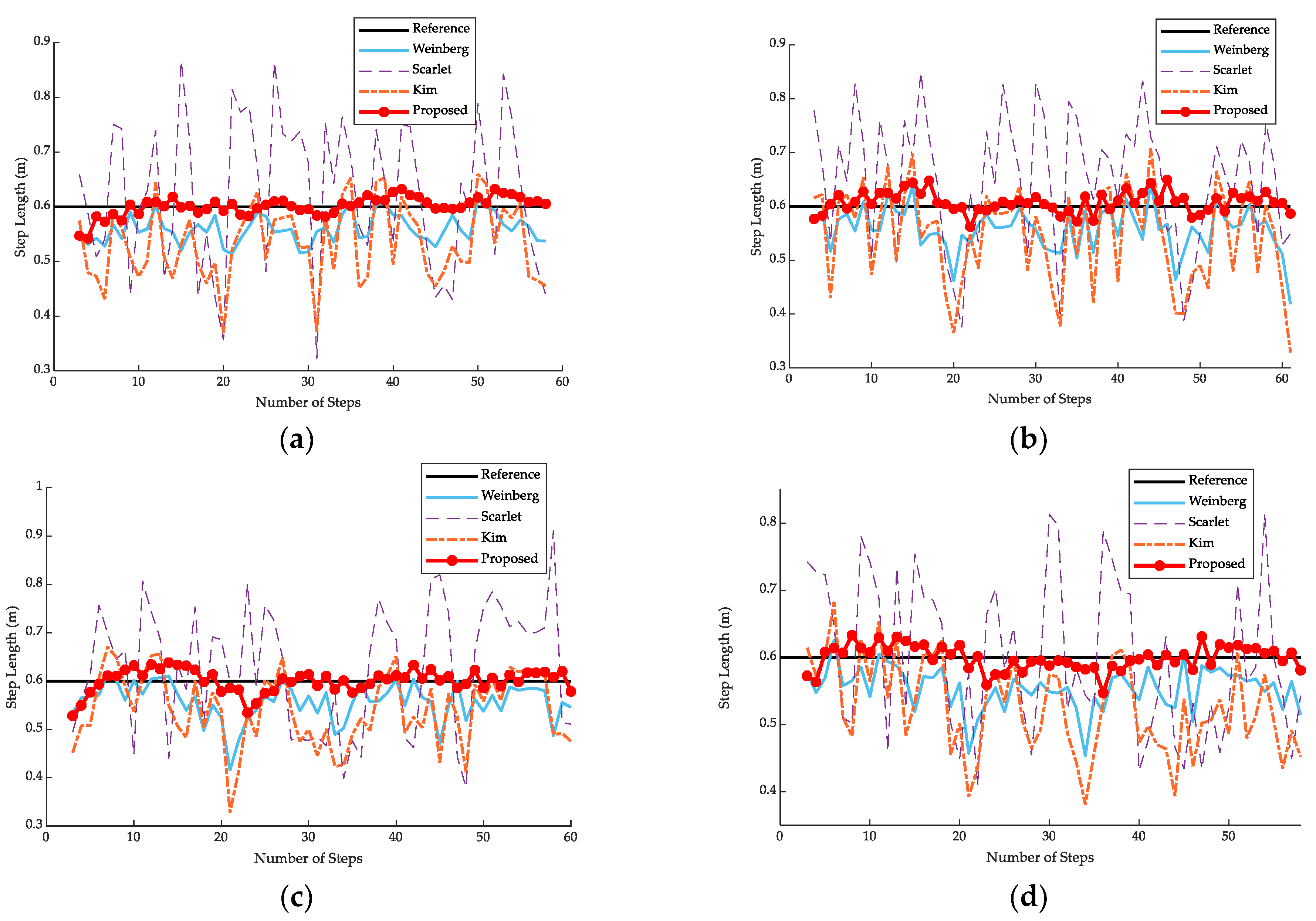
To evaluate the proposed step length method, we performed experiments with the Scarlet, Kim, Weinberg, and proposed models. Figure 9 demonstrates the results of step length estimation at the first experimental site when the pedestrian walks at a speed of 0.6 m/step. Figure 9 shows that the proposed method achieves better performance than the Scarlet, Kim, and Weinberg models with different user heights and different devices. These results primarily occur because the proposed model can identify more accurate information to calculate the step length for each time step.
Table 2 shows the step length estimation with the VivoY85a and Honor60 smartphones in the first scene with the various models. The step length estimation of the proposed model is more accurate than the other models. Comparing these methods, the proposed method achieves performances near the true value for different persons. Equipment heterogeneity can thus be managed effectively.
For the second scenario, Figure 10 demonstrates the step length estimation results when the different pedestrians with VivoY85a and Honor60 smartphones walk with a speed of 0.6 m/step. These results illustrate that the proposed model achieves a higher accuracy than the other models in the second scenario. Whether there is equipment heterogeneity or different users, the proposed method achieves good performance.
Table 3 shows the step length estimation with the VivoY85a and Honor60 smartphones in the second scene with the various models. Results illustrate that the proposed model achieves a higher accuracy primarily because the proposed model can consider more information than the other models. Additionally, the adaptive computation of attention at each step allows for the prediction of more accurate pedestrian states.
In addition, we conducted some experiments to estimate step length with different distances at the trial site. We recruited three volunteers to capture the data with the corridor totaling 15 m, 24 m, and 33 m. Five sets of data from the inertial sensors were collected every time. Table 4 shows the distance estimation and absolute errors for each volunteer, which demonstrate that errors increase with longer distances. However, our method is more accurate than the Weinberg method. The errors of the proposed model are less than 1.5% primarily because the proposed method considers more accurate information when estimating the distances.

5.2.3. Improved Dynamic PDR Results

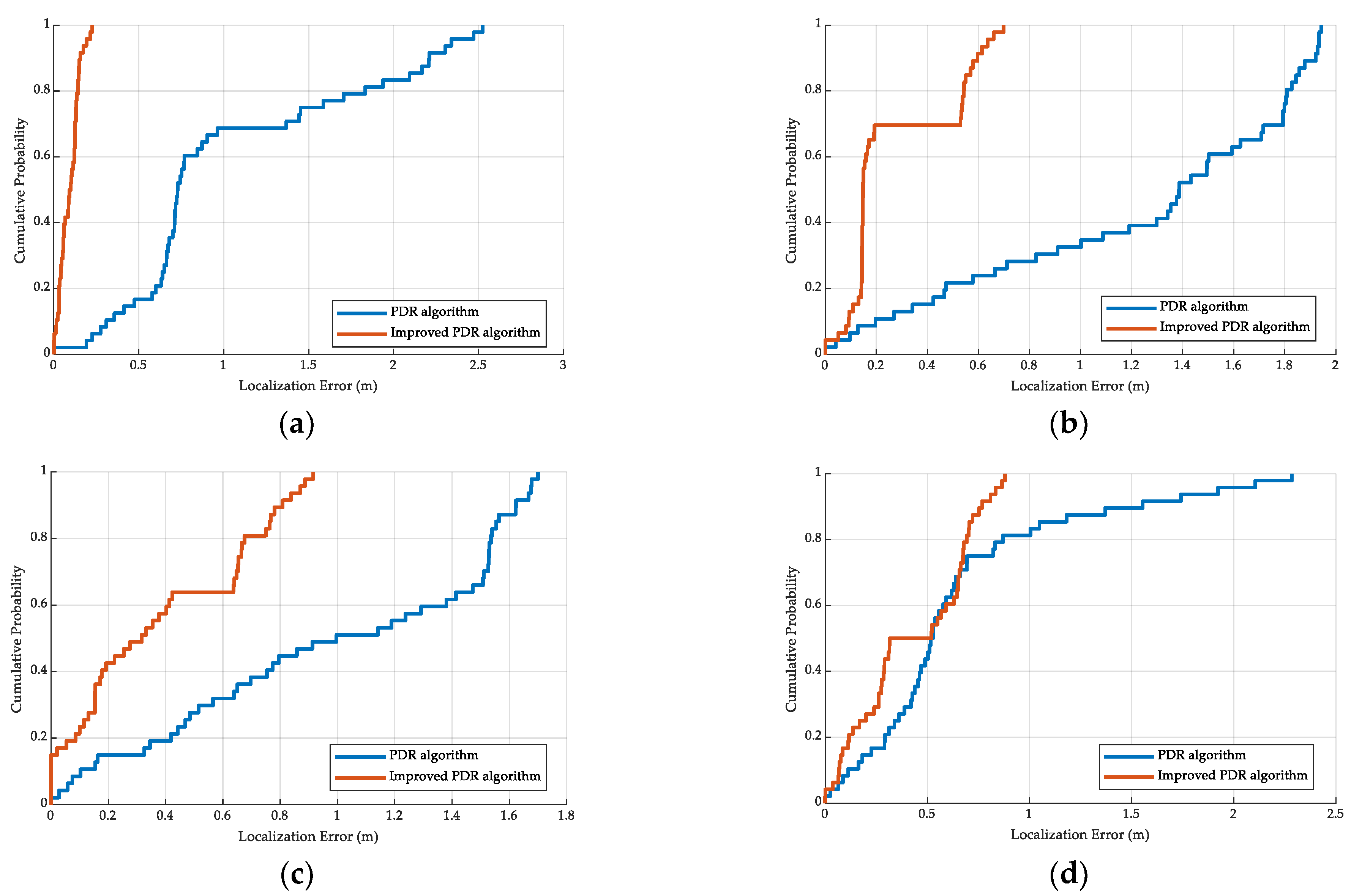
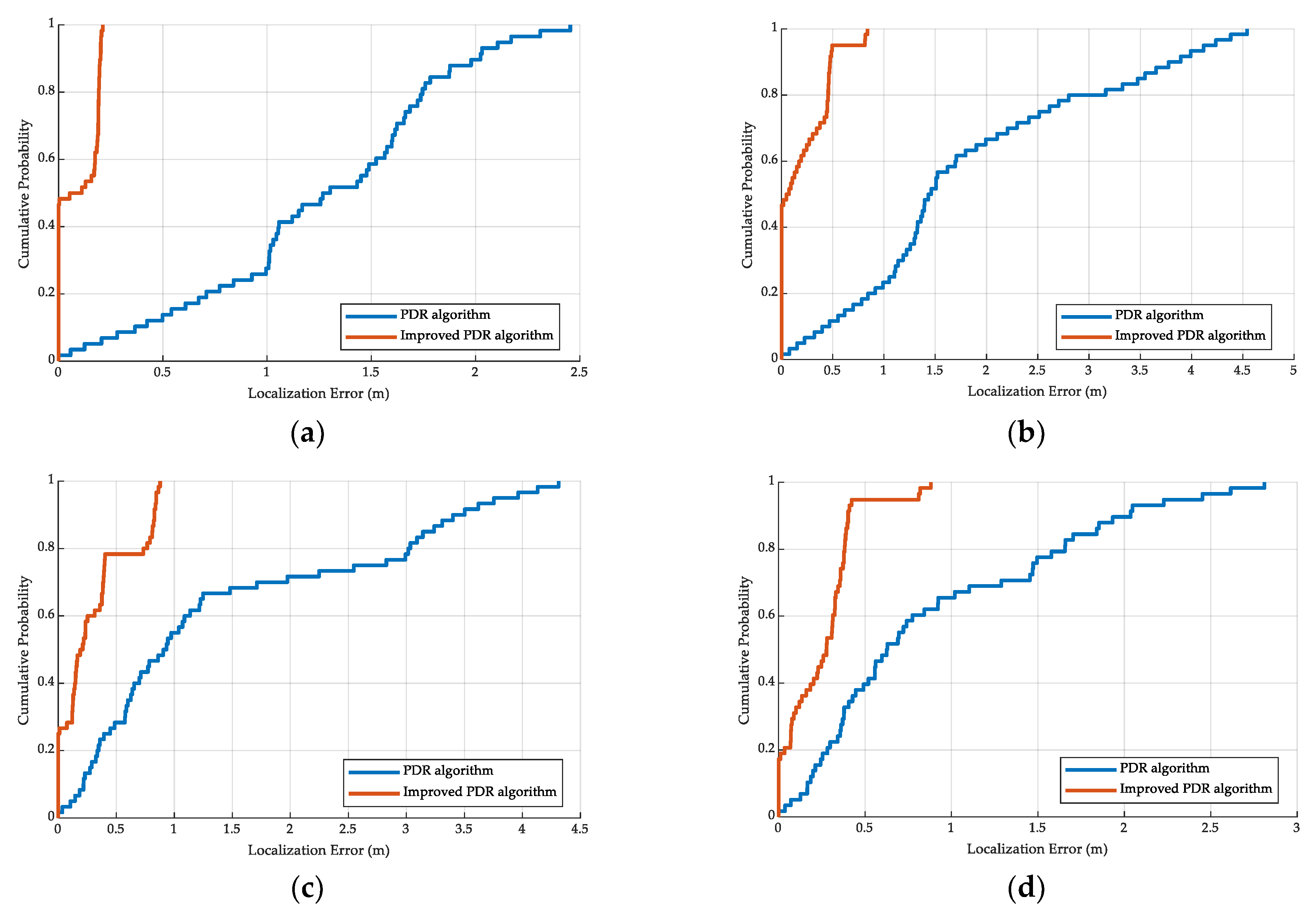
To evaluate the generality of the improved PDR method to different devices, users, and environments, we conducted experiments with VivoY85a and Honor60 smartphones and two volunteers in the two trial sites. Figure 11 and Figure 12 show the cumulative density function (CDF) of the localization error with different devices, users, and environments. The experimental results show that the improved PDR method has a lower localization error and better performance than the traditional PDR method. These results primarily occur because step length estimation and heading direction compensation were calculated based on more accurate information, thus reducing the effects of device heterogeneity and achieving comparable localization error with different users (height 155 cm and 180 cm) in different environments.

5.3. Localization Performance

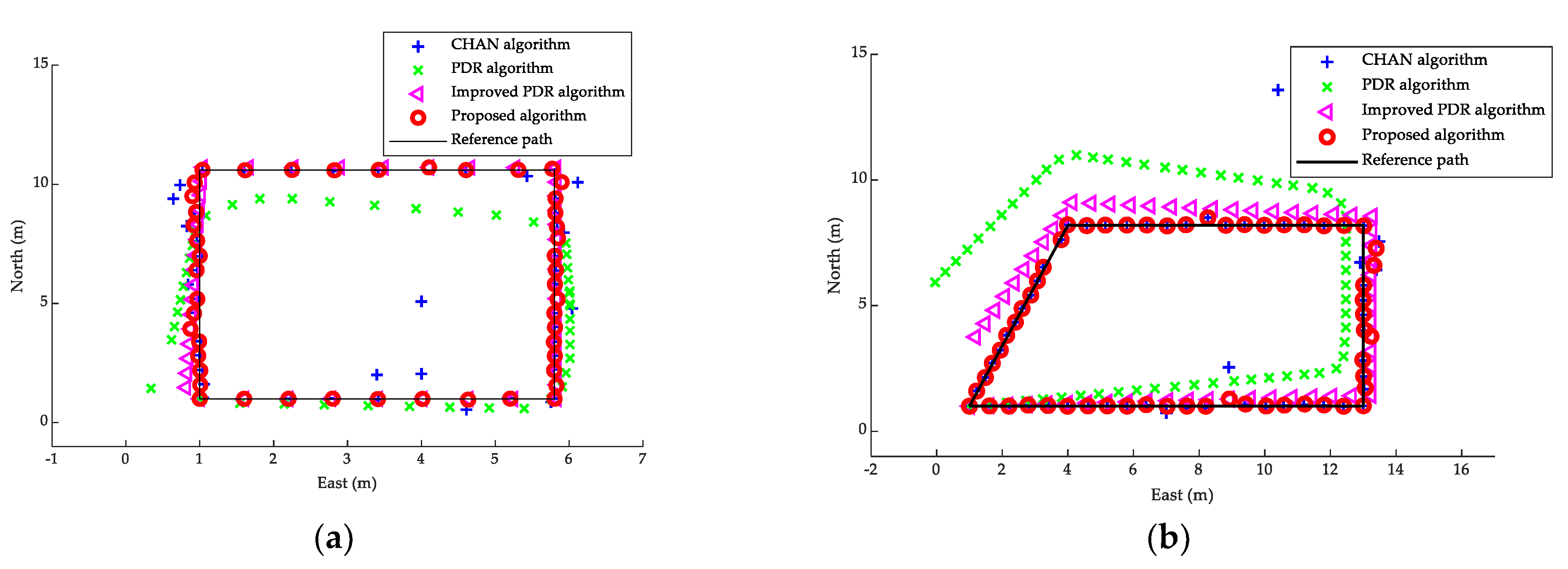
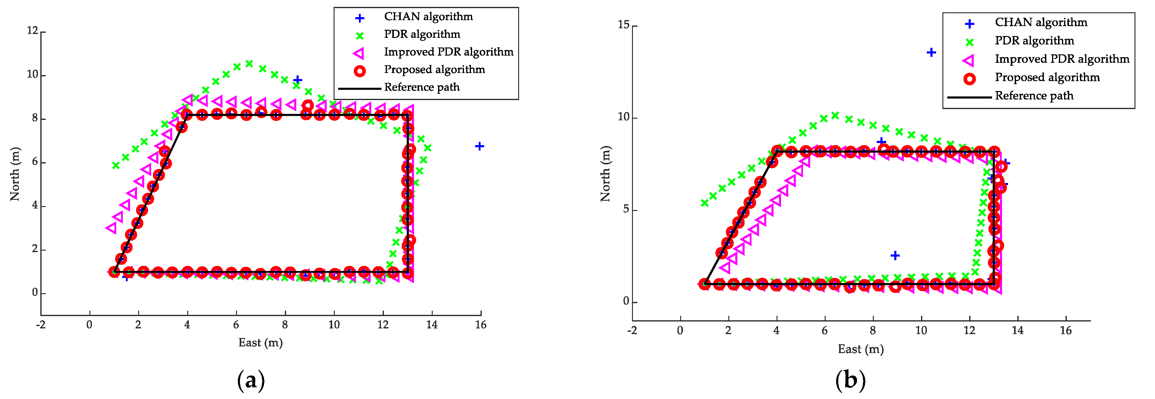
We performed several experiments of localization performance on the global region at the two trial sites. Figure 13 shows the localization results using CHAN, PDR, improved PDR, and the proposed method at the two trial sites. These results show that the localization of the CHAN algorithm and the PDR algorithm is affected by the environment. Some abnormities occur in the acoustic localization, and cumulative errors occur over time in the PDR algorithm. However, the improved PDR algorithm and proposed algorithm can achieve better accuracy and effectively suppress the abnormity and cumulative errors. This result is attributed to the following reasons. First, the proposed PDR method can effectively extract accurate information to estimate location. In addition, we proposed error judgment criteria to eliminate anomalous values. The proposed method thus exhibits good generality for different environments.
Figure 14 shows the localization results using CHAN, PDR, improved PDR, and the proposed method with different devices at the trial sites and demonstrates that there is equipment heterogeneity in the CHAN and PDR estimation. The proposed method can achieve comparable localization performance in the survey path primarily because the proposed method can effectively compensate for the equipment difference and suppress the errors. The proposed method thus achieves better performance with different devices compared to the other tested methods.
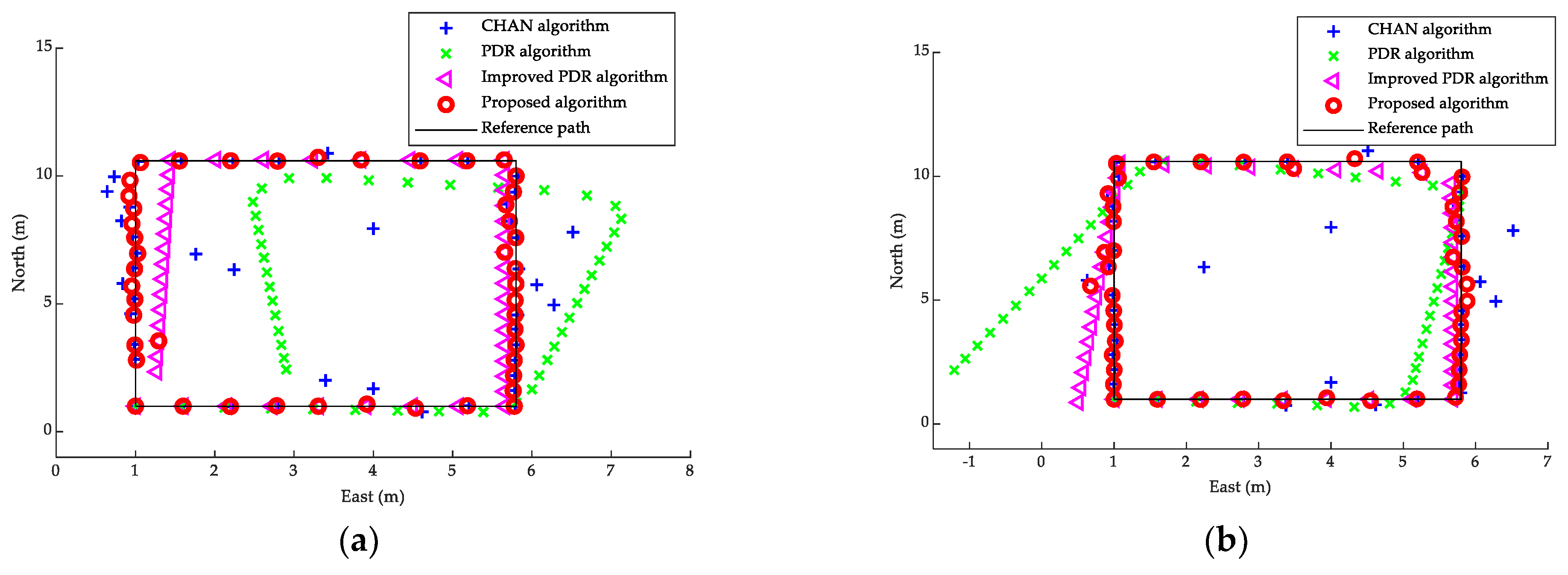
Figure 15 shows the localization results using CHAN, PDR, improved PDR, and the proposed method with different height pedestrians at the trial sites. These results show that different heights cause different errors in the estimation algorithms. However, the proposed method achieves good accuracies with different user heights along the survey path because the proposed method can effectively compensate for the errors that different user heights create.
Figure 16 demonstrates the mean localization errors between CHAN, PDR, dynamic improved PDR, and the proposed method for different devices, scenes, and step counting. These results show that the proposed method achieves comparable localization accuracy with different length paths, devices, and pedestrians. The proposed method achieves the best localization performance compared to CHAN, PDR, and dynamic improved PDR because the proposed threshold scheme suppresses outliers caused by the environment in the base-acoustic estimation and the cumulative errors caused by PDR estimation over time.
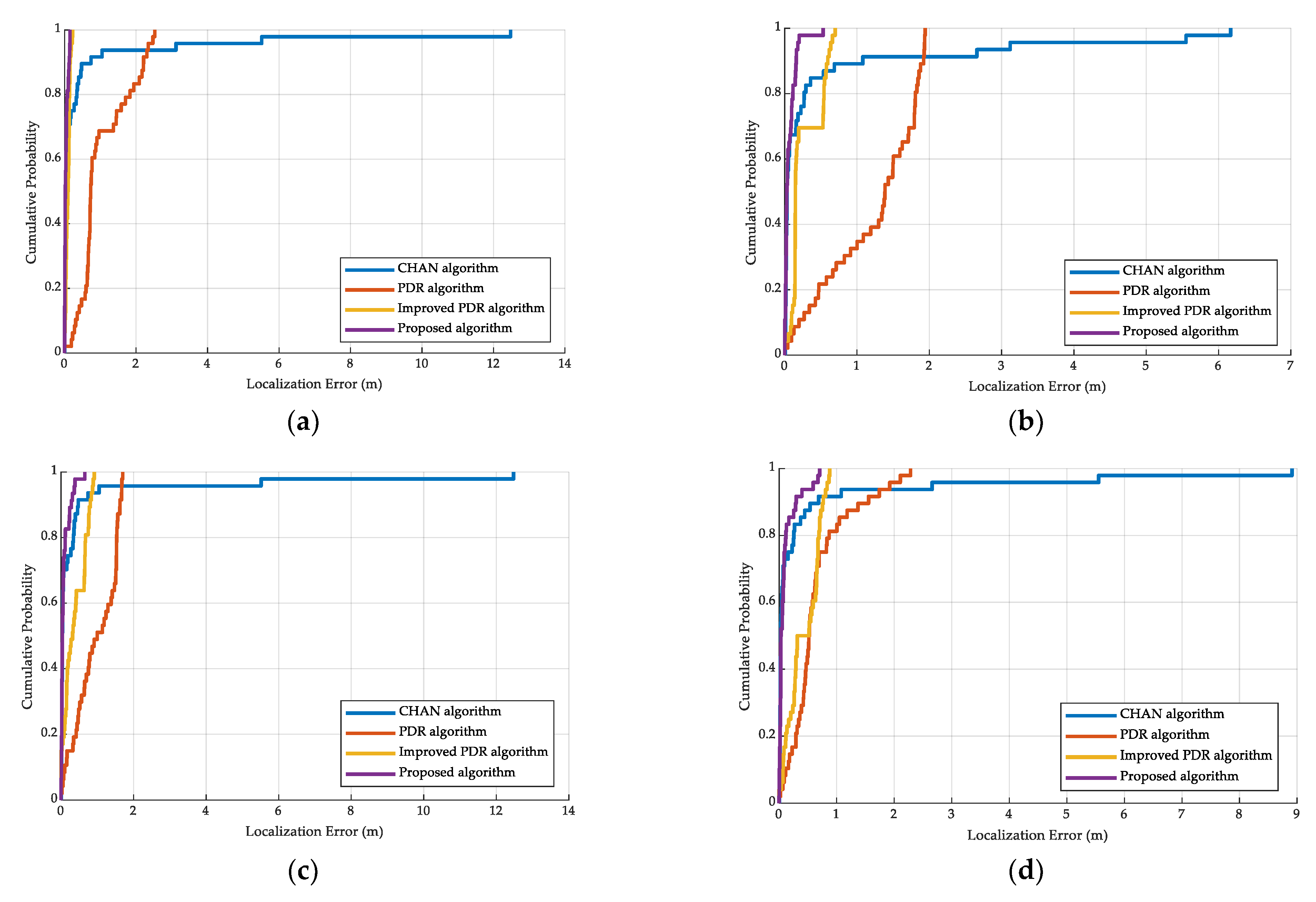
We show the CDFs of the localization errors in the first scenario shown in Figure 17. The experiments demonstrate our proposed method achieves sufficient accuracy compared to the CHAN, PDR, and the improved PDR estimation in different devices and different pedestrians. This result occurs because the generation of weight values can accurately calculate the importance between the CHAN and improved PDR estimation, and the localization scheme can detect invalid estimation.
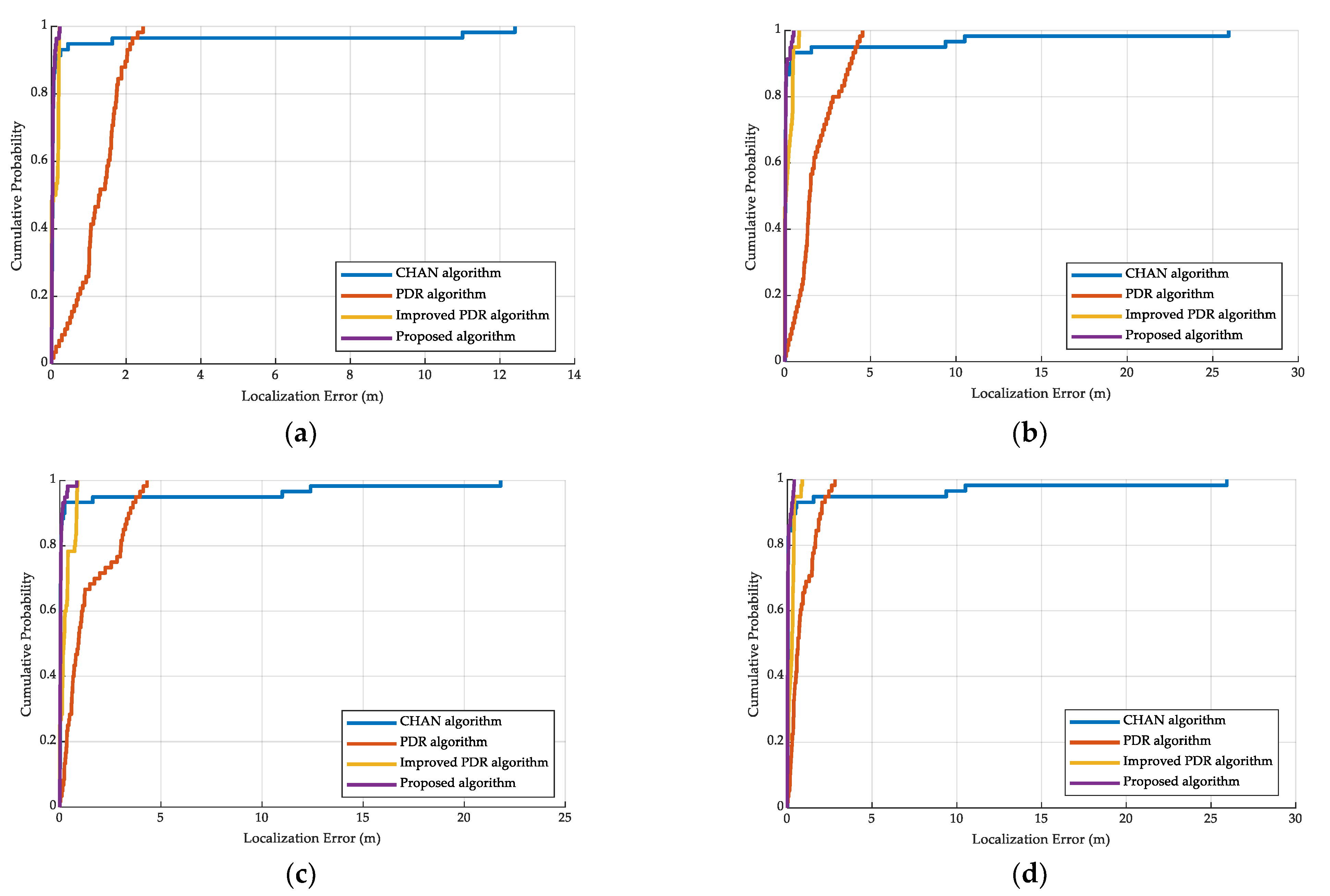
We compare the CDFs of the localization error in the second scenario in Figure 18. The experiments show that our proposed algorithm in a larger environment also achieves higher accuracy than the CHAN, PDR, and improved PDR estimation in different devices and different pedestrians. These results occur because the generation of weight values can obtain the importance in the CHAN and the improved PDR estimations.
Table 5 and Table 6 show the localization errors of the 90th percentile in the two scenes for different pedestrians and different devices. The experiments show that the localization accuracy of the proposed method has greater improvement than the CHAN, PDR, and the improved PDR method. Our method thus achieves good generality and flexibility in different pedestrians, devices, and scenes.
We present that the mean errors and root mean squared errors (RMSE) of the CHAN, PDR, improved PDR, and the proposed method in the trial scenes in Table 7 and Table 8. For the two scenes, the experiments demonstrate that our method markedly improves localization performance with different equipment, users, and scenes. The proposed method effectively eliminates errors generated by environments, devices, and human behaviors.
In addition, we compare the calculation complexity between our proposed algorithm and CHAN algorithm in two scenes. In the first scene, totaled 48 times, it ran 13.0944 s using the CHAN algorithm and 13.8225 s using the proposed method, respectively. In the second scene, totaled 60 times, it consumed 14.0062 s using the CHAN algorithm and 15.0488 s using the proposed method. The experiments show that our method is comparable with the CHAN method and has better localization performance.

6. Conclusions

In this paper, we propose a CHAN-IPDR-ILS indoor localization system that incorporates CHAN estimation and an improved PDR method. In the CHAN-IPDR-ILS, ultrasonic localization is implemented using the CHAN algorithm. In the localization system, we propose a step length estimation model that estimates location using the previous two steps and current accelerations. To ensure the importance of the current state, the maximum importance for the previous step length is set. In addition, we propose a heading direction correction method that adds a correction angle and a compensation error. The proposed method can correct the heading direction and mitigate issues of equipment heterogeneity. Finally, in the fusion localization, the distance threshold is set to mitigate accidental errors during acoustic localization. Pedestrian localization is then determined based on the distance confidence level with acoustic estimation and improved PDR estimation. We conducted experiments at two trial sites in which the first scene covered approximately 96 m2 and the second scene covered approximately 224 m2. Two different height volunteers with a VivoY85a smartphone and an Honor60 smartphone captured data along the survey path at each scene, respectively. The experimental results demonstrate that the proposed method can achieve a higher location accuracy compared to existing methods using different smart devices. In addition, we compared the computational complexity of the proposed CHAN-IPDR-ILS in two scenes. The CHAN-IPDR-ILS has comparable performance with the CHAN estimation. The proposed localization system satisfies the public demand. The proposed CHAN-IPDR-ILS provides high generality and flexibility for different devices and scenarios and is compatible with smartphones in terms of low cost and high accuracy. With excellent localization performance, low cost, and short execution time, it can be concluded that the proposed CHAN-IPDR-ILS is a charming indoor localization method for practical deployment. Future research directions include more complex environments, such as more shadows and reflections. The smartphone is hung for answering calls, and is carried in the pocket, waist, etc. Inspired by deep learning, another direction may be considered based on a lightweight deep learning method.

Author Contributions

Conceptualization, S.Y.; Data curation, C.W.; Funding acquisition, S.Y. and J.X.; Methodology, J.X.; Project administration, Y.J.; Resources, X.L.; Software, X.L.; Writing—original draft, C.W.; Writing—review and editing, Y.J. All authors have read and agreed to the published version of the manuscript.

Funding

This work was supported in part by National Natural Science Foundation of China: Grant 62061010, Grant 62161007, Grant 61936002, Grant 62033001, and Grant 6202780103; Guangxi science and Technology Project: Grant AA20302022, Grant AB21196041, Grant AB22035074, and Grant AD22080061; National Key Research and Development Program: Grant 2018AA100305; Guilin Science and Technology Project: Grant 20210222-1; Bagui scholar program Fund (2019A40) of Guangxi Zhuang Autonomous Region of China; The Project of Improving the Basic Research Ability of Young and Middle-aged Teachers in Guangxi Universities (2022KY0181); Guangxi Key Laboratory of Precision Navigation Technology and Application: Grant 202206 and Grant 202210; Innovation Project of Guangxi Graduate Education: YCSW2022291.

Institutional Review Board Statement

Not applicable.

Informed Consent Statement

Not applicable.

Data Availability Statement

All test data mentioned in this paper will be made available on request to the corresponding author’s email with appropriate justification.

Conflicts of Interest

The authors declare no conflict of interest.

Abbreviations

The following abbreviations are used in this manuscript:
SymbolQuantity
s m Data Step length of the m-th step
β m Heading direction of the m-th step after correction
β m e a s Measured heading direction using smartphone
β s t a t i c Compensation error of heading direction
d i j Distance difference between beacons Ai and Aj on the target
d i Distance between beacon Ai and target M
e Error vector
Σ Covariance matrix
Y Ordinary least squares
U m c Ultrasonic-base localization estimation
x i 1 Difference between the horizontal coordinates of the i-th beacon and the first beacon
y i 1 Difference between the vertical coordinates of the i-th beacon and the first beacon
r i Sum of the squares of the horizontal and vertical coordinates of point i
K Model parameter
b i Weight vector
U m Location estimation at time m
U m p Location estimation using PDR method at time m
C o n f C Distance confidence level for ultrasonic-base estimation
C o n f P Distance confidence level for improved PDR estimation
D t h Distance threshold

References

  1. Yassin, A.; Nasser, Y.; Awad, M.; Al-Dubai, A.; Liu, R.; Yuen, C.; Raulefs, R.; Aboutanios, E. Recent Advances in Indoor Localization: A Survey on Theoretical Approaches and Applications. IEEE Commun. Surv. Tutor. 2017, 19, 1327–1346. [Google Scholar] [CrossRef] [Green Version]
  2. Li, Z.; Wang, R.; Gao, J.; Wang, J. An approach to improve the positioning performance of GPS/INS/UWB integrated system with two-step filter. Remote Sens. 2017, 10, 19. [Google Scholar] [CrossRef] [Green Version]
  3. Zheng, Y.; Zeng, Q.; Lv, C.; Yu, H.; Ou, B. Mobile Robot Integrated Navigation Algorithm Based on Template Matching VO/IMU/UWB. IEEE Sens. J. 2021, 21, 27957–27966. [Google Scholar] [CrossRef]
  4. Li, J.; Xue, J.; Fu, D.; Gui, C.; Wang, X. Position Estimation and Error Correction of Mobile Robots Based on UWB and Multisensors. J. Sens. 2022, 2022, 1–18. [Google Scholar] [CrossRef]
  5. Wu, W.; Fu, S.; Luo, Y. Practical Privacy Protection Scheme In WiFi Fingerprint-based Localization. In Proceedings of the 2020 IEEE 7th International Conference on Data Science and Advanced Analytics (DSAA), Sydney, Australia, 6–9 October 2020; pp. 699–708. [Google Scholar]
  6. Poulose, A.; Han, D.S. Hybrid Deep Learning Model Based Indoor Positioning Using Wi-Fi RSSI Heat Maps for Autonomous Applications. Electronics 2021, 10, 2. [Google Scholar] [CrossRef]
  7. Want, R.; Hopper, A.; Falcao, V.; Gibbons, J. The Active Badge Location System. Acm. T Inform. Syst. 1992, 10, 91–102. [Google Scholar] [CrossRef]
  8. Zhu, J.; Xu, H. Review of RFID-based indoor positioning technology. In International Conference on Innovative Mobile and Internet Services in Ubiquitous Computing(IMIS); Abertay University: Matsue, Japan, 2018; pp. 632–641. [Google Scholar]
  9. Yang, B.Y.; Yang, E.F. A Survey on Radio Frequency based Precise Localisation Technology for UAV in GPS-denied Environment. J. Intell. Robot. Syst. 2021, 103, 1–30. [Google Scholar] [CrossRef]
  10. Florio, A.; Avitabile, G.; Coviello, G. A Linear Technique for Artifacts Correction and Compensation in Phase Interferometric Angle of Arrival Estimation. Sensors 2022, 22, 1427. [Google Scholar] [CrossRef]
  11. Florio, A.; Avitabile, G.; Coviello, G. Multiple Source Angle of Arrival Estimation Through Phase Interferometry. IEEE Trans. Circuits Syst. Ii-Express Briefs 2022, 69, 674–678. [Google Scholar] [CrossRef]
  12. Paulino, N.; Pessoa, L.M. Self-Localization via Circular Bluetooth 5.1 Antenna Array Receiver. IEEE Access 2023, 11, 365–395. [Google Scholar] [CrossRef]
  13. Zhou, C.; Yuan, J.Z.; Liu, H.Z.; Qiu, J. Bluetooth Indoor Positioning Based on RSSI and Kalman Filter. Wirel. Pers. Commun. 2017, 96, 4115–4130. [Google Scholar] [CrossRef]
  14. Yao, Y.B.; Bao, Q.J.; Han, Q.; Yao, R.L.; Xu, X.R.; Yan, J.R. BtPDR: Bluetooth and PDR-Based Indoor Fusion Localization Using Smartphones. Ksii Trans. Internet Inf. Syst. 2018, 12, 3657–3682. [Google Scholar] [CrossRef]
  15. Jiang, C.; Liu, J. A smartphone-based indoor geomagnetic positioning system. GNSS Word China 2018, 43, 9–16. [Google Scholar]
  16. Wang, Q.; Zhou, J. Simultaneous localization and mapping method for geomagnetic aided navigation. Optik 2018, 171, 437–445. [Google Scholar] [CrossRef]
  17. Elloumi, W.; Latoui, A.; Canals, R.; Chetouani, A.; Treuillet, S. Indoor Pedestrian Localization With a Smartphone: A Comparison of Inertial and Vision-Based Methods. IEEE Sens. J. 2016, 16, 5376–5388. [Google Scholar] [CrossRef]
  18. Fischer, G.; Bordoy, J.; Schott, D.J.; Xiong, W.X.; Gabbrielli, A.; Hoflinger, F.; Fischer, K.; Schindelhauer, C.; Rupitsch, S.J. Multimodal Indoor Localization: Fusion Possibilities of Ultrasonic and Bluetooth Low-Energy Data. IEEE Sens. J. 2022, 22, 5857–5868. [Google Scholar] [CrossRef]
  19. Dai, S. Design and implementation of ultrasonic-based indoor positioning system. Southwest Jiaotong Univ. 2017. [Google Scholar]
  20. Gentner, C.; Ulmschneider, M.; Jost, T. Cooperative simultaneous localization and mapping for pedestrians using low-cost ultra-wideband system and gyroscope. In Proceedings of the 2018 IEEE/ION Position, Location and Navigation Symposium (PLANS), Monterey, CA, USA, 23–26 April 2018; pp. 1197–1205. [Google Scholar]
  21. Hauschildt, D.; Kirchhof, N. Advances in thermal infrared localization: Challenges and solutions. In Proceedings of the 2010 International Conference on Indoor Positioning and Indoor Navigation, Zurich, Switzerland, 15–17 September 2010; pp. 1–8. [Google Scholar]
  22. Ajroud, C.; Hattay, J.; Machhout, M. Holographic Multi-Reader RFID Localization Method for Static Tags. In Proceedings of the 2022 8th International Conference on Control, Decision and Information Technologies (CoDIT), Istanbul, Turkey, 17–20 May 2022; pp. 1393–1396. [Google Scholar]
  23. Song, S.; Feng, F.; Xu, J. Review of Geomagnetic Indoor Positioning. In Proceedings of the 2020 IEEE 4th International Conference on Frontiers of Sensors Technologies (ICFST), Shanghai, China, 6–9 November 2020; pp. 30–33. [Google Scholar]
  24. Xing, H.; Guo, S.; Shi, L.; Hou, X.; Liu, Y.; Hu, Y.; Xia, D.; Li, Z. Quadrotor vision-based localization for amphibious robots in amphibious area. In Proceedings of the 2019 IEEE International Conference on Mechatronics and Automation (ICMA), Tianjin, China, 4–7 August 2019; pp. 2469–2474. [Google Scholar]
  25. Yanovsky, F.J.; Sinitsyn, R.B. Application of wideband signals for acoustic localization. In Proceedings of the 2016 8th International Conference on Ultrawideband and Ultrashort Impulse Signals (UWBUSIS), Odessa, Ukraine, 5–11 September 2016; pp. 27–35. [Google Scholar]
  26. Lu, Y.; Wei, D.; Yuan, H. A Magnetic-Aided PDR Localization Method Based on the Hidden Markov Model. In Proceedings of the 30th International Technical Meeting of the Satellite Division of The Institute of Navigation (ION GNSS+ 2017), Portland, OR, USA, 25–29 September 2017; pp. 3331–3339. [Google Scholar]
  27. Mazlan, A.B.; Ng, Y.H.; Tan, C.K. A Fast Indoor Positioning Using a Knowledge-Distilled Convolutional Neural Network (KD-CNN). IEEE Access 2022, 10, 65326–65338. [Google Scholar] [CrossRef]
  28. Mazlan, A.B.; Ng, Y.H.; Tan, C.K. Teacher-Assistant Knowledge Distillation Based Indoor Positioning System. Sustainability 2022, 14, 4652. [Google Scholar] [CrossRef]
  29. Gu, H.; Zhao, K.; Yu, C.; Zheng, Z. High resolution time of arrival estimation algorithm for B5G indoor positioning. Phys. Commun. 2022, 50, 101494. [Google Scholar] [CrossRef]
  30. Yao, S.; Su, Y.; Zhu, X. Technology. High Precision Indoor Positioning System Based on UWB/MINS Integration in NLOS Condition. J. Electr. Eng. 2022, 17, 1–10. [Google Scholar]
  31. Zhang, S.; Wang, W.; Jiang, T. Wi-Fi-inertial indoor pose estimation for microaerial vehicles. IEEE Trans. Ind. Electron. 2020, 68, 4331–4340. [Google Scholar] [CrossRef] [Green Version]
  32. Zhu, Q.; Niu, K.; Dong, C.; Wang, Y. A novel angle of arrival (AOA) positioning algorithm aided by location reliability prior information. In Proceedings of the 2021 IEEE Wireless Communications and Networking Conference (WCNC), Nanjing, China, 29 March 2021–1 April 2021; pp. 1–6. [Google Scholar]
  33. Deng, Z.; Wang, H.; Zheng, X.; Fu, X.; Yin, L.; Tang, S.; Yang, F. A closed-form localization algorithm and GDOP analysis for multiple TDOAs and single TOA based hybrid positioning. Appl. Sci. 2019, 9, 4935. [Google Scholar] [CrossRef] [Green Version]
  34. Qu, J.; Shi, H.; Qiao, N.; Wu, C.; Su, C.; Razi, A. Networking. New three-dimensional positioning algorithm through integrating TDOA and Newton’s method. EURASIP J. Wirel. Commun. 2020, 2020, 1–8. [Google Scholar]
  35. Fang, B.T. Simple solutions for hyperbolic and related position fixes. IEEE Trans. Aerosp. Electron. Syst. 1990, 26, 748–753. [Google Scholar] [CrossRef]
  36. Chan, Y.T.; Ho, K.C. A simple and efficient estimator for hyperbolic location. IEEE Trans. Signal Process. 1994, 42, 1905–1915. [Google Scholar] [CrossRef] [Green Version]
  37. Poulose, A.; Han, D.S. UWB indoor localization using deep learning LSTM networks. Appl. Sci. 2020, 10, 6290. [Google Scholar] [CrossRef]
  38. Kolakowski, M. Improving accuracy and reliability of bluetooth low-Energy-Based localization systems using proximity sensors. Appl. Sci. 2019, 9, 4081. [Google Scholar] [CrossRef] [Green Version]
  39. Zhang, F. Fusion positioning algorithm of indoor WiFi and bluetooth based on discrete mathematical model. J. Ambient. Intell. Humaniz. Comput. 2020, 1–11. [Google Scholar] [CrossRef]
  40. Jia, B.; Huang, B.Q.; Gao, H.P.; Li, W.; Hao, L.F. Selecting Critical WiFi APs for Indoor Localization Based on a Theoretical Error Analysis. IEEE Access 2019, 7, 36312–36321. [Google Scholar] [CrossRef]
  41. Liu, K.K.; Liu, X.X.; Li, X.L. Guoguo: Enabling Fine-Grained Smartphone Localization via Acoustic Anchors. IEEE Trans. Mob. Comput. 2016, 15, 1144–1156. [Google Scholar] [CrossRef]
  42. Luo, X.N.; Wang, H.C.; Yan, S.Q.; Liu, J.M.; Zhong, Y.R.; Lan, R.S. Ultrasonic localization method based on receiver array optimization schemes. Int. J. Distrib. Sens. Netw. 2018, 14, 1–13. [Google Scholar] [CrossRef]
  43. Li, L.; Liu, Z. Analysis of TDOA Algorithm about Rapid Moving Target with UWB Tag. In Proceedings of the 2017 9th International Conference on Intelligent Human-Machine Systems and Cybernetics (IHMSC), Hangzhou, China, 26–27 August 2017; pp. 406–409. [Google Scholar]
  44. Lee, G.T.; Seo, S.B.; Jeon, W.S. Indoor localization by Kalman filter based combining of UWB-positioning and PDR. In Proceedings of the 2021 IEEE 18th Annual Consumer Communications & Networking Conference (CCNC), Las Vegas, NV, USA, 9–12 January 2021; pp. 1–6. [Google Scholar]
  45. Wang, H.; Luo, X.; Zhong, Y.; Lan, R.; Wang, Z. Acoustic signal positioning and calibration with IMU in NLOS environment. In Proceedings of the 2019 Eleventh International Conference on Advanced Computational Intelligence (ICACI), Guilin, China, 7–9 June 2019; pp. 223–228. [Google Scholar]
  46. Yan, S.; Wu, C.; Deng, H.; Luo, X.; Ji, Y.; Xiao, J. A Low-Cost and Efficient Indoor Fusion Localization Method. Sensors 2022, 22, 5505. [Google Scholar] [CrossRef] [PubMed]
  47. Liu, R.; Yuen, C.; Do, T.N.; Tan, U.X. Fusing Similarity-Based Sequence and Dead Reckoning for Indoor Positioning Without Training. IEEE Sens. J. 2017, 17, 4197–4207. [Google Scholar] [CrossRef]
  48. Zhu, Y.; Luo, X.; Guan, S.; Wang, Z. Indoor positioning method based on WiFi/Bluetooth and PDR fusion positioning. In Proceedings of the 2021 13th International Conference on Advanced Computational Intelligence (ICACI), Wanzhou, China, 14–16 May 2021; pp. 233–238. [Google Scholar]
  49. Weinberg, H. Using the ADXL202 in pedometer and personal navigation applications. Analog. Devices AN-602 Appl. Note 2002, 2, 1–6. [Google Scholar]
  50. Scarlett, J. Enhancing the perdormance of pedometers using a single accelerometer. Appl. Note Analog. Devices 2007, 41, 1–16. [Google Scholar]
  51. Kim, J.W.; Jang, H.J.; Hwang, D.H.; Park, C. A Step, Stride and Heading Determination for the Pedestrian Navigation System. J. Glob. Position. Syst. 2004, 3, 273–279. [Google Scholar] [CrossRef] [Green Version]
  52. Zhao, Q.; Zhang, B.; Wang, J. Improved method of step length estimation based on inverted pendulum mode. Int. Iournal Distrib. Sens. Netw. 2007, 13, 1–13. [Google Scholar]
  53. Song, H. Research and Implentation of Indoor Navigation System Based on Pedestrian Dead Reckoning. Univ. Electron. Sci. Technol. China 2018. [Google Scholar]
Figure 1. Localization system scheme combining ultrasonic signals and inertial signals.
Applsci 13 03270 g001
Figure 2. Motion model diagram of the target, where T i ,   i = 1 ,   2 ,   3 ,   is the trajectory of the target.
Applsci 13 03270 g002
Figure 3. Time domain, frequency domain, and time−frequency characteristic of chirp signal with time duration of 40 ms between 17.5 and 19.5 kHz.
Applsci 13 03270 g003
Figure 4. Spatial geometric location map with three beacons ( A 1 ,   A 2 ,   A 3 ) and the target T.
Applsci 13 03270 g004
Figure 5. Localization of the proposed heading direction method with different devices. (a) VivoY85a cell phone. (b) Honor60 cell phone.
Applsci 13 03270 g005
Figure 6. Trial experimental site floor plans. (a) Scenario 1. (b) Scenario 2.
Applsci 13 03270 g006
Figure 7. Peak and valley detection results with Honor60, VivoY85a, and two different height pedestrians in the first scene. (a) Volunteer #1 with a VivoY85a cell phone. (b) Volunteer #2 with a VivoY85a cell phone. (c) Volunteer #1 with an Honor60 cell phone. (d) Volunteer #2 with an Honor60 cell phone.
Applsci 13 03270 g007
Figure 8. The peak and valley detection results with Honor60, VivoY85a, and two different height pedestrians in the second scene. (a) Volunteer #1 with a VivoY85a cell phone. (b) Volunteer #2 with a VivoY85a cell phone. (c) Volunteer #1 with an Honor60 cell phone. (d) Volunteer #2 with an Honor60 cell phone.
Applsci 13 03270 g008aApplsci 13 03270 g008b
Figure 9. Step length estimation results with Honor60, VivoY85a, and two different height pedestrians in the first scene. (a) Volunteer #1 with a VivoY85a cell phone. (b) Volunteer #2 with a VivoY85a cell phone. (c) Volunteer #1 with an Honor60 cell phone. (d) Volunteer #2 with an Honor60 cell phone.
Applsci 13 03270 g009
Figure 10. Step length estimation results with Honor60, VivoY85a, and two different height pedestrians in the second scene. (a) Volunteer #1 with a VivoY85a cell phone. (b) Volunteer #2 with a VivoY85a cell phone. (c) Volunteer #1 with an Honor60 cell phone. (d) Volunteer #2 with an Honor60 cell phone.
Applsci 13 03270 g010
Figure 11. The CDF of localization errors between our PDR and PDR algorithms in the first scene. (a) Volunteer #1 with a VivoY85a cell phone. (b) Volunteer #2 with a VivoY85a cell phone. (c) Volunteer #1 with an Honor60 cell phone. (d) Volunteer #2 with an Honor60 cell phone.
Applsci 13 03270 g011
Figure 12. The CDF of localization errors between our PDR and PDR algorithms in the second scene. (a) Volunteer #1 with a VivoY85a cell phone. (b) Volunteer #2 with a VivoY85a cell phone. (c) Volunteer #1 with an Honor60 cell phone. (d) Volunteer #2 with an Honor60 cell phone.
Applsci 13 03270 g012
Figure 13. Localization path results among CHAN, PDR, dynamic improved PDR, and the proposed algorithm at the two scenes. (a) Volunteer #1 with a VivoY85a cell phone in the first scene. (b) Volunteer #2 with a VivoY85a cell phone in the second scene.
Applsci 13 03270 g013
Figure 14. Localization path results among CHAN, PDR, improved PDR, and the proposed algorithm using the VivoY85a and Honor60 smartphones in the first scene. (a) Volunteer #2 with a VivoY85a cell phone in the first scene. (b) Volunteer #2 with an Honor60 cell phone in the first scene.
Applsci 13 03270 g014
Figure 15. Localization path results among CHAN, PDR, improved PDR, and the proposed algorithm with two different height pedestrians. (a) Volunteer #1 (height 155 cm). (b) Volunteer #2 (height 180 cm).
Applsci 13 03270 g015
Figure 16. Mean localization errors among CHAN, PDR, improved PDR, and the proposed algorithm with different step counts. (a) Volunteer #2 with a VivoY85a cell phone (scene 1). (b) Volunteer #2 with a VivoY85a cell phone (scene 2). (c) Volunteer #1 with a VivoY85a cell phone (scene 2). (d) Volunteer #1 with an Honor60 cell phone (scene 2).
Applsci 13 03270 g016aApplsci 13 03270 g016b
Figure 17. The CDFs of the localization errors among the CHAN algorithm, PDR algorithm, improved PDR algorithm, and the proposed algorithm in the first scene. (a) Volunteer #1 with a VivoY85a cell phone (scene 1). (b) Volunteer #2 with a VivoY85a cell phone (scene 1). (c) Volunteer #1 with an Honor60 cell phone (scene 1). (d) Volunteer #1 with an Honor60 cell phone (scene 1).
Applsci 13 03270 g017
Figure 18. The CDFs of the localization errors among the CHAN algorithm, PDR algorithm, improved PDR algorithm, and the proposed algorithm in the second scene. (a) Volunteer #1 with a VivoY85a cell phone (scene 2). (b) Volunteer #2 with a VivoY85a cell phone (scene 2). (c) Volunteer #1 with an Honor60 cell phone (scene 2). (d) Volunteer #2 with an Honor60 cell phone (scene 2).
Applsci 13 03270 g018
Table 1. Mobile phone technical information.
Technical InformationVivoY85aHonor60
Operating systemAndroid 8.1.0Android 11
CPUSnapdragon 450 Snapdragon 778
RAM + ROM4 G + 64 G8 G + 256 G
Screen6.26 inch6.67 inch
Image resolution2280 × 10802400 × 1080
Battery capacity3260 mAh4800 mAh
Table 2. Step length estimation with Honor60, VivoY85a, and two different height pedestrians in the first scene.
MethodVolunteer #1 (m)Volunteer #2 (m)
Scarlet (VivoY85a)0.66210.6453
Scarlet (Honor60)0.61900.5619
Kim (VivoY85a)0.53750.5238
Kim (Honor60)0.54180.4859
Weinberg (VivoY85a)0.55320.5514
Weinberg (Honor60)0.56080.5494
Proposed method (VivoY85a)0.60780.5956
Proposed method (Honor60)0.60660.5952
Table 3. Step length estimation with Honor60, VivoY85a, and two different height pedestrians in the second scene.
MethodVolunteer #1 (m)Volunteer #2 (m)
Scarlet (VivoY85a)0.62450.6490
Scarlet (Honor60)0.62800.6018
Kim (VivoY85a)0.53510.5466
Kim (Honor60)0.54220.5272
Weinberg (VivoY85a)0.56020.5583
Weinberg (Honor60)0.55760.5548
Proposed method (VivoY85a)0.60130.6075
Proposed method (Honor60)0.60090.5992
Table 4. Distance estimation and absolute error results between the Weinberg model and the proposed model with different pedestrians and distances (m).
DistanceNumberWeinberg MethodProposed Method
Distance EstimationAbsolute ErrorDistance EstimationAbsolute Error
15 m114.11030.889715.19360.1936
213.91901.081014.79650.2035
313.86301.137015.02100.0210
24 m122.15981.840223.96900.0310
222.43311.566924.20470.2047
322.35251.647523.85150.1485
33 m130.85242.147633.04970.0497
230.56102.439033.07420.0742
330.85072.149333.40020.4002
Table 5. The CDF of localization error with Honor60, VivoY85a, and two different height pedestrians in the first scene (m).
Method90th Percentile (Volunteer #1)90th Percentile (Volunteer #2)
CHAN (VivoY85a)0.74051.0800
CHAN (Honor60)0.47420.6856
PDR (VivoY85a)2.21001.9215
PDR (Honor60)1.62231.5540
Improved PDR (VivoY85a)0.15560.5968
Improved PDR (Honor60)0.80850.7678
Proposed method (VivoY85a)0.13370.1597
Proposed method (Honor60)0.28520.2956
Table 6. The CDF of localization error with Honor60, VivoY85a, and two different height pedestrians in the second scene (m).
Method90th Percentile (Volunteer #1)90th Percentile (Volunteer #2)
CHAN (VivoY85a)0.17450.3967
CHAN (Honor60)0.24430.4873
PDR (VivoY85a)2.02313.8940
PDR (Honor60)3.50362.0372
Improved PDR (VivoY85a)0.20140.4758
Improved PDR (Honor60)0.82830.4026
Proposed method (VivoY85a)0.08610.1387
Proposed method (Honor60)0.13050.2571
Table 7. Localization error results between CHAN, PDR, improved PDR, and the proposed method with Honor60, VivoY85a, and two different height pedestrians in the first scene (m).
Volunteer #1MethodMean ErrorRMS Error
CHAN (VivoY85a)0.45631.8913
CHAN (Honor60)0.40501.8565
PDR (VivoY85a)1.04171.2482
PDR (Honor60)0.97081.1240
Improved PDR (VivoY85a)0.09210.1083
Improved PDR (Honor60)0.37550.4822
Proposed method (VivoY85a)0.04320.0632
Proposed method (Honor60)0.09040.1574
Volunteer #2
CHAN (VivoY85a)0.47801.3898
CHAN (Honor60)0.41951.5492
PDR (VivoY85a)1.22131.3730
PDR (Honor60)0.65650.8382
Improved PDR (VivoY85a)0.26810.3416
Improved PDR (Honor60)0.43040.5097
Proposed method (VivoY85a)0.06700.1112
Proposed method (Honor60)0.10540.1956
Table 8. Localization error results between CHAN, PDR, improved PDR, and the proposed method with Honor60, VivoY85a, and two different height pedestrians in the second scene (m).
Volunteer #1MethodMean ErrorRMS Error
CHAN (VivoY85a)0.24001.4719
CHAN (Honor60)0.25861.4613
PDR (VivoY85a)1.25921.3911
PDR (Honor60)1.42591.9098
Improved PDR (VivoY85a)0.09370.1322
Improved PDR (Honor60)0.30300.4273
Proposed method (VivoY85a)0.03900.0580
Proposed method (Honor60)0.06430.1406
Volunteer #2
CHAN (VivoY85a)0.23911.2526
CHAN (Honor60)0.25431.2768
PDR (VivoY85a)1.82992.1867
PDR (Honor60)0.90141.1565
Improved PDR (VivoY85a)0.19420.3075
Improved PDR (Honor60)0.24790.3193
Proposed method (VivoY85a)0.06100.1227
Proposed method (Honor60)0.06150.1176
Disclaimer/Publisher’s Note: The statements, opinions and data contained in all publications are solely those of the individual author(s) and contributor(s) and not of MDPI and/or the editor(s). MDPI and/or the editor(s) disclaim responsibility for any injury to people or property resulting from any ideas, methods, instructions or products referred to in the content.