Article

Detection of Underwater Targets Using Polarization Laser Assisted Echo Detection Technique

1
College of Computer Science, Changchun University of Science and Technology, Changchun 130022, China
2
College of Opto-Electronic Engineering, Changchun University of Science and Technology, Changchun 130022, China
3
Science and Technology Branch, Changchun University of Science and Technology, Changchun 130022, China
4
College of Telecommunication, Changchun University of Science and Technology, Changchun 130022, China
*
Author to whom correspondence should be addressed.
Appl. Sci. 2023, 13(5), 3222; https://doi.org/10.3390/app13053222
Submission received: 24 November 2022 / Revised: 16 January 2023 / Accepted: 17 January 2023 / Published: 2 March 2023

Abstract

:
At present, polarization imaging detection experiments of underwater objects mainly focus on the degree of polarization but lack of Stokes vector imaging effect of each element. Based on the principle that the polarization characteristics of different materials are different, the experiment of underwater target detection by laser pulse polarization is carried out in this paper, and the influence of different depths of an underwater object and material factors on polarization imaging detection is studied. The results show that in air, the average degree of polarization of iron sheet is 0.56, that of ceramic tile is 1.00, and that of plastic is 0.48. In water, the average degree of polarization of iron sheet is 0.3625 at 7.5 m, the average degree of polarization of ceramic tile at 7.5 m is 0.359, and that of plastic at 7.5 m is 0.3805. The medium will change the degree of polarization of the measured object. The targets made of different materials have different polarization characteristics, and the polarization information is of great value in improving the detection performance of man-made targets. Polarization detection can obtain better information about underwater objects than traditional radiation intensity detection and can effectively suppress the absorption and scattering of light by water.

1. Introduction

With the deepening of scientific research, the polarization characteristics of light were discovered, and laser polarization detection, a new laser detection technology, was proposed to become a powerful auxiliary technical means in laser underwater target detection technology with a broad application space. Polarization, as an inherent and independent property of light waves, also contains abundant information on reflection and scattering from an object’s surface, which can improve the detection ability of object imaging.
Zhe Chen et al. [1] proposed a new light intensity-spectrum-polarization based bionic information fusion target detection method for the special underwater optical environment, which can get rid of the tedious image preprocessing process by adaptive feature fusion algorithm based on the obtained underwater optical a priori knowledge and achieve reliable target detection results at the cost of lower computational complexity. Bao Fucheng et al. [2] used a SALSA camera to obtain underwater polarization images under natural illumination, and studied the effects of different material objects, placement depth, milk concentration and waveband factors on the polarization imaging of underwater targets, and found that the blue band polarization imaging can better obtain the boundary contour of underwater objects and other information. The underwater polarization imaging technique developed by Fei Liu [3] and others from the polarization characteristics of the light field can effectively suppress the scattered light from the underwater background and use the polarization difference characteristics of the target information light and the scattered light from the background to effectively separate the two and achieve clear imaging. Zhao Yongqiang et al. [4] analyzed the corresponding polarization characteristics of target information light, backward scattered light and forward scattered light and targeted to solve the influence of different components on the image and thus realize the improvement of image quality. Li Yingchao et al. [5] proposed a method to detect the wake of underwater targets by using infrared polarization wake with a low-orbiting satellite as a platform, combining laser dynamic depth measurement technology and polarization laser detection technology to achieve the detection and identification of underwater stealthy moving targets. Yang Fan [6] proposed a novel scheme for acquiring polarization information of reflected light from underwater targets based on the Stokes matrix representation and split-amplitude method and completed the research on the key technology of laser polarization diving detection by describing the working principle and implementation steps in the scheme, building the system, and analyzing the laser transmission attenuation energy. Wang Lijie [7] researched the multi-scale decomposition method based on boosted wavelet transform for image fusion enhancement processing to improve the quality of polarized images in view of the problems of poor quality, blurred texture details and low contrast of underwater polarized images. Liu Xiao et al. [8] carried out experiments on the detection of polarization characteristics of camouflaged targets and studied the relationship between observation angle, target surface roughness, material, etc. Nianwen Cao et al. [9] carried out experiments on polarization imaging technology to improve the imaging clarity and imaging distance by quantitatively calculating the clarity of the imaging image, the quantitative relationship between the clarity of the polarization image and the distance, and found that when the water quality is clear, the imaging effect of circular polarization is better than the imaging effect of linear polarization, and as the attenuation coefficient of the water body becomes larger, the imaging effect of linear polarization is better than the important conclusion of circular polarization.
Compared with traditional target detection, the material properties are not only determined by the target temperature but also by the roughness of the target surface, material, observation angle and other factors. Polarization imaging can obtain the surface roughness and internal structure of the measured object according to the polarization characteristics of reflected and transmitted light and can obtain clear underwater images under the thousand perturbations of particle scattered light. This paper aims to verify the function of laser polarization underwater detectors and explore the different polarization of different objects in different environments for identification. Laser underwater target polarization detection provides a new way of thinking for target identification and detection in an underwater environment, overcomes various interference noise underwater, realizes fast measurement and accurate identification, and has important research significance in the field of ocean and space exploration.

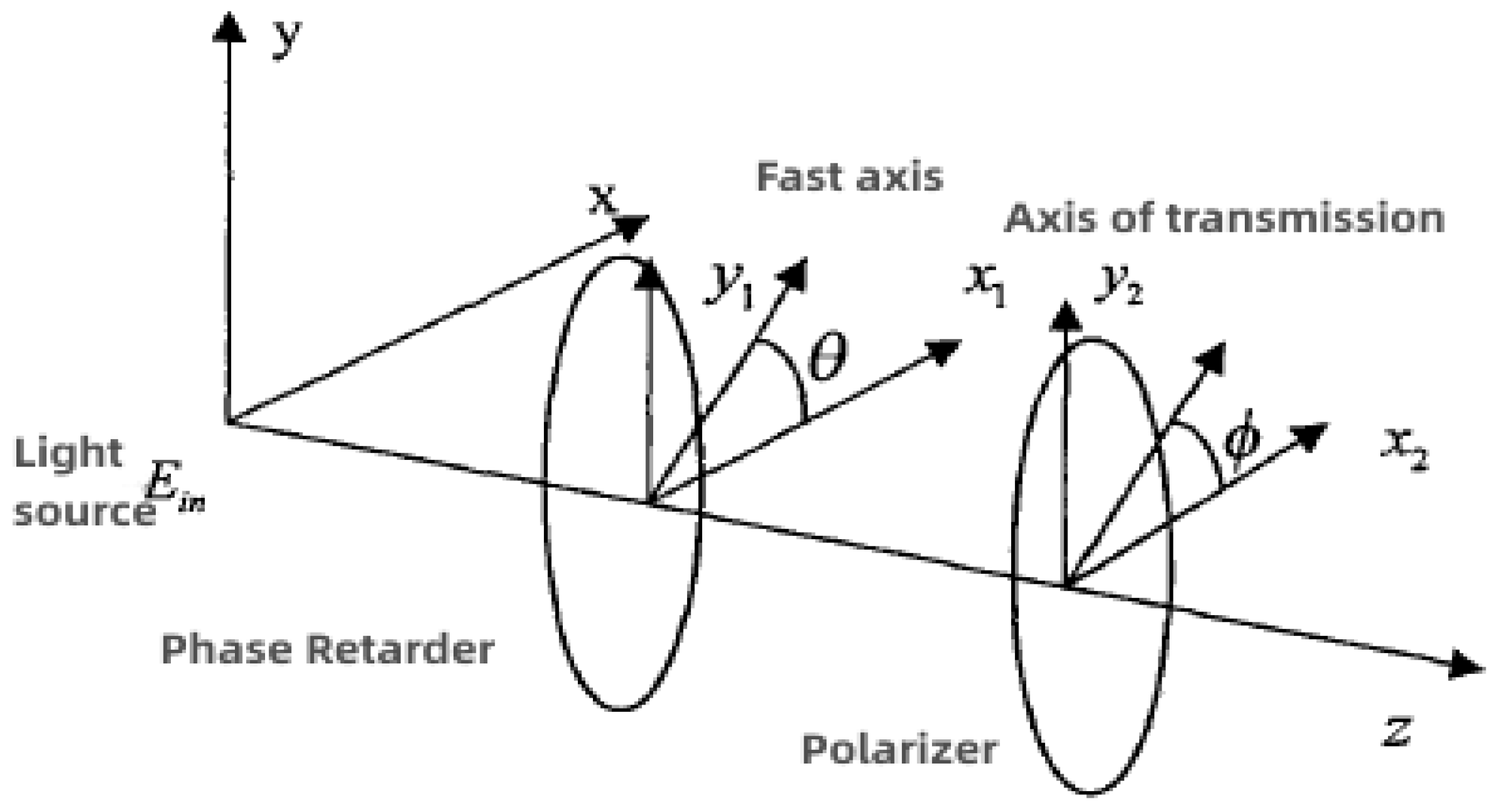
2. Underwater Target Polarization Detection Mechanism

As known from physics, light is an electromagnetic wave; electromagnetic waves are a kind of wave with vector characteristics, which includes electric field vector component E and magnetic field vector component B, two components [10]. The dominant quantity that can play a light-sensitive role is the electric field vector component E so that the electric field vector E is usually called the light vector, the vibration of this vector is usually called light vibration, and the direction of vibration of this vector as the direction of vibration of light.
From the optics part of physics, it is known that the light in the ordinary light source is generated by the vibration of a large number of molecules or atoms that make up the light source. The light atoms or molecules in either of these light processes are intermittent; they are re-emitting or re-emitting at each time. The phase and the direction of vibration will change some so that the light of the ordinary light source contains vibrations in all directions and this vibration in each direction with equal probability of occurrence. This instantaneous light-emitting process in the plane perpendicular to the direction of light propagation appears in the statistical distribution of mathematical probability, is equal to the probability distribution and is called natural light, the sun, life in fluorescent lamps, tungsten lamps, etc., issued by the light belongs to the natural light.
If a beam of light only in a certain direction vibration or vibration dominance, using mathematical probability statistics to explain the probability of occurrence in a certain direction is equal to one or the probability of occurrence in a certain direction is greater than the probability of occurrence in other directions, this light is called polarized light. There are four kinds of light with polarization state: partially polarized light, linearly polarized light, elliptically polarized light and circularly polarized light.
When a beam of light irradiates an object, the object will act on the light, let the outgoing beam is E o u t , the incident beam is E i n , then the four Stokes parameters E o u t will be respectively with the four corresponding parameters E i n into a linear function of the relationship [11], if the matrix can be written in the form of Equation (1).
S out   = M × S in  
where represents the Stokes vector parameter S o u t of the outgoing light E o u t , S i n represents the Stokes vector parameter of the incoming light E i n , and M is a Mueller matrix of (4 × 4) order [12], by which the properties and characteristic orientation of the medium of such an irradiated object can be represented. A polarization device is an object that allows light to pass through if a beam of light irradiates the polarization device and passes through the polarization device. The change in the Stokes vector between the incident and outgoing light can be considered as the result of the role of the polarization device; the resulting effect is represented by the matrix M.
By analogy, if the light beam E i n passes through several such devices in turn, the properties of the outgoing light E o u t can be calculated by knowing the properties of the devices through which the light passes and the properties of the light itself. If L optical elements are passed E i n in turn, the total effect can be expressed by Equation (2).
M comb   = M L M L 1 M 2 M 1
The above equation M L represents the M-matrix of the E i n action of the Lth element pair, with the elements passing through the order from 1 to L. In polarization measurement systems, the polarizer (usually a line polarizer) and the phase delay (usually a quarter wave plate is used) are very important basic optical elements, as shown in Figure 1.
A beam of light propagates E i n along the Z-axis direction and passes through the phase delayers (the fast-axis direction is at an angle θ to the X-axis direction) and a line polarizer (the polarization direction is at an angle φ to the X-axis) in turn. The Stokes parameters can be obtained by rotating the phase delayers and polarizers, and this rotational measurement parameter method is highlighted below. Through the above introduction, we know that the Stokes vector has four basic parameters, and to solve them completely, at least four equations are needed. If a quarter wavelet (a kind of phase delay) and a line polarizer are placed on the measurement line, where when the direction of the fast axis of the quarter wavelet is at an angle θ to the X- axis, the M matrix of the wavelet can be expressed by Equation (3).
M b = 1 0 0 0 0 cos 2 2 θ cos 2 θ sin 2 θ sin 2 θ 0 cos 2 θ sin 2 θ sin 2 2 θ cos 2 θ 0 sin 2 θ cos 2 θ 0
When the polarization direction of the linear polarizer is at an angle φ to the X-axis, Equation (4) can express the M-matrix of the polarizer.
M P = 1 cos 2 ϕ sin 2 ϕ 0 cos 2 ϕ cos 2 2 ϕ sin 2 ϕ cos 2 ϕ 0 sin 2 ϕ sin 2 ϕ cos 2 ϕ sin 2 2 ϕ 0 0 0 0 0
Then the Stokes vector S o u t of the incident light E o u t can be expressed in Equation (5), which I indicates the total intensity of the light, the intensity Q difference between the horizontal (X-axis) polarization and the vertical (Y-axis) polarization, the intensity U difference between 45 degrees and 135 degrees in the direction of the polarized part of the light, and the intensity V difference between the left and right circular components of the light.
S out   = I Q U V = M 2 M 1 S in   = M 2 M 1 I Q U V
The light intensity expression is shown in Equation (6):
I φ , θ = 1 2 I + 1 2 cos 2 φ ( Q × cos 2 2 θ + U × cos 2 θ sin 2 θ V × sin 2 θ ) + 1 2 sin 2 φ ( Q × cos 2 θ sin 2 θ + U × sin 2 2 θ + V × cos 2 θ )
If four angles (0°, 45°, 90° and 135°) are given when the phasor is horizontal, and the intensities measured at these four angles are noted as I 1 , I 2 , I 3 , I 4 , then a system of equations consisting of the three equations represented by Equation (7) is obtained.
I Q U = 1 2 ( I 1 + I 2 + I 3 + I 4 ) I 1 I 3 I 2 I 4 = I 1 + I 3 I 1 I 3 I 2 I 4
When the phaser is at a 45° angle to the horizontal direction, φ take 0 degrees, and the light intensity I 5 is recorded as:
I 5 = 1 2 ( I V )
The parameters derived from Equations (5)–(7) are Sir George Stokes, 1st Baronet vector parameters, and the degree of polarization DOP can be obtained by substituting these parameters into Equation (9) [13].
D O P = Q 2 + U 2 + V 2 I
In many practical remote sensing applications, the parameter V is usually so small that the error of the experimental system can be ignored, i.e., treated as zero. In this way, only the first three parameters are required, a quarter of the wave plate with phase delay effect is not needed, only a linear polarizer is needed, and the angles of 0°, 45°, 90° and 135° are taken, at the same time, the light intensity I 1 , I 2 , I 3 , I 4 of the three parameters can be measured separately, that is, Equation (7).
The formula for calculating the degree of linear polarization can be simplified by Formula (10).
D O P = Q 2 + U 2 I
At the same time, the polarization azimuth can be expressed by Formula (11).
α = 1 2 arctan U Q

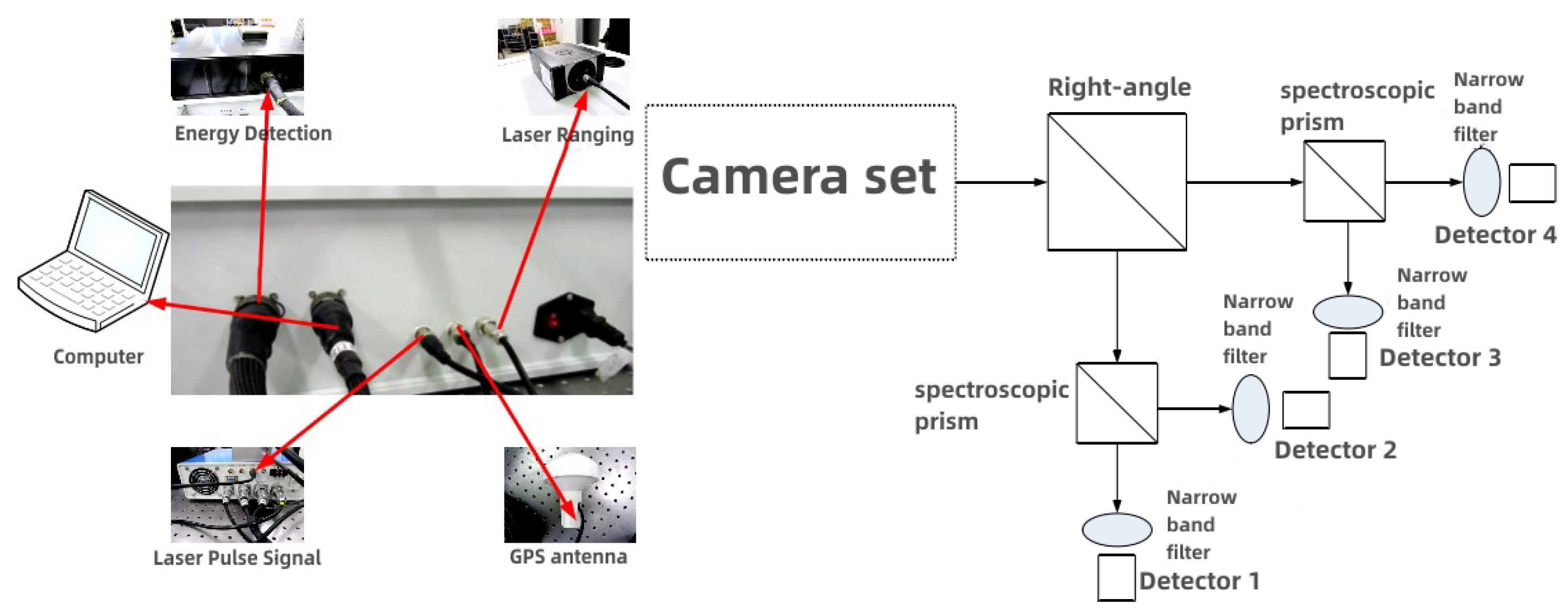
3. Underwater Target Polarization Detection System and Experimental Scheme

3.1. Setting Up and Testing of the Experimental Environment

The pulsed ranging method is to transmit a laser beam to the measured target and then measures the round-trip time of the laser to achieve distance detection by receiving the echo signal from the target after diffuse reflection. Figure 2 shows the schematic diagram of pulsed laser ranging.
The underwater laser polarization detection system includes a 532 nm Pulse Laser, a laser ranging module, a polarization energy detection module, and a seawater tank. The hardware connection diagram and the system experimental schematic diagram are shown in Figure 3. The experiment includes the measurement of weak laser energy, polarization characteristic, distance and location.
Connect all the hardware devices as shown in Figure 3, start the computer software, turn on the hardware power switch, power on the control box, and wait for the device to connect. After connecting, the status bar shows the database connection and device connection. Set the computer parameters, laser frequency, ranging parameters and new test project name, and set the new test project as the current test project. Turn on the power supply of the laser and prepare to start the test. Through the corresponding buttons on the toolbar, the corresponding operation will be zero, zero, start the measurement, pause the measurement, stop the measurement operation, and zero the detector before the measurement, according to the actual situation of the test operation. Test data will be automatically written to the database and displayed. Data processing, polarization degree and polarization angle will be automatically calculated after the measurement; calculation generated terrain grid. Select the list data from the view, and the flat, three-dimensional view is displayed.

3.2. Energy Test and Polarization Test

The performance of the energy probe used in the polarization detection equipment was evaluated, including full range calibration, dynamic range, non-linearity and Conformance testing. The test data are shown in Table 1.
Different targets are placed at different distances to test the energy of the reflected echo at 0°, 45°, 90°and 135°. The test process is shown in Figure 4, and several sets of test data are selected for Table 2.
Build an underwater test environment using a seawater tank, as shown in Figure 5. The pure water is injected into the pool, and different targets are placed in the pool at different distances. The energy of echo at 0°, 45°, 90° and 135° is measured after the laser passes through the water. The test process is shown in Figure 5, Figure 6 shows the structure of the simulated pool and several sets of test data are selected for Table 3.
Light intensity imaging techniques are generally affected by environmental factors, and in harsh environments, imaging will have a certain degree of difficulty because the light intensity is too weak. While infrared imaging is subject to errors caused by the ambient temperature, polarization imaging technology can perform long-range image acquisition operations in harsh environments and has advantages in suppressing background noise, improving detection distance, detailed feature acquisition, and target camouflage identification.

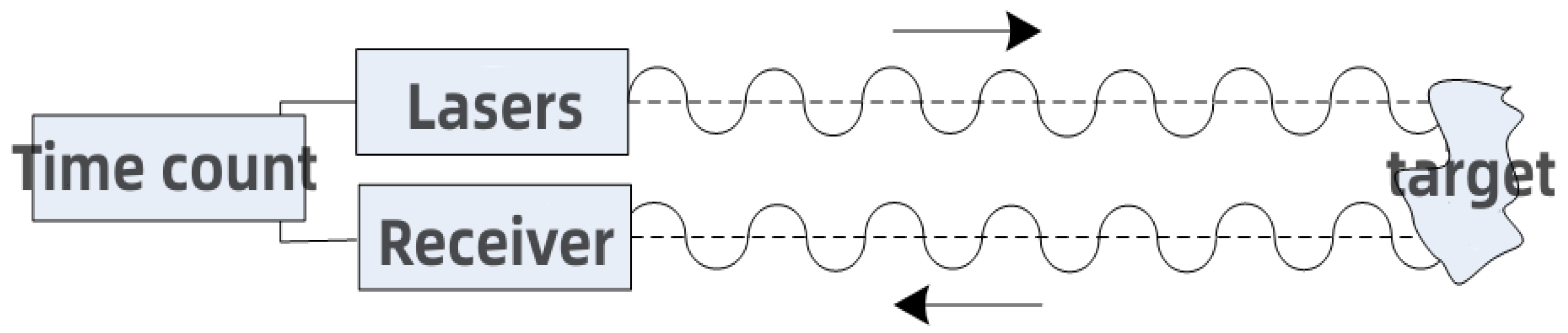
3.3. Distance Test and Location Test

The laser ranging module calculates the distance by using the time of the reflected light from the target. Due to the different transmission speeds of the light in air and water, the testing depth needs to be corrected.
According to the refractive index of water and air, the transmission speed of light in water is about C water = C air / 1.33 . If the actual ranging distance is d, the distance between the ranging module and the water surface is h, and the actual water depth is x, then:
d C air = h C a i r + x C w a t e r
x = d h / 1.33
When the depth of water is corrected, only the distance between the ranging module and the water surface and the refractive index of the tested water body is needed. However, the ranging module has a certain angle of inclination when incident. The incident angle is i, the refraction angle is r, the refractive index of the water body is n, then the actual water depth is
x = d h cos i n cos ( arcsin ( sin i n ) )

4. Results and Analysis

4.1. The Influence of Polarization Characterization

At the same energy point, four probes were used to measure the inconsistency of the four probes. The maximum deviation of the four measurements was divided by two times the average of the four measurements to obtain the error value; the experimental data of the four probes are shown in Table 1. The table is plotted as shown in Figure 7. The energy obtained by the four probes is the same under the same environmental conditions, and the error is controlled at about 2%.

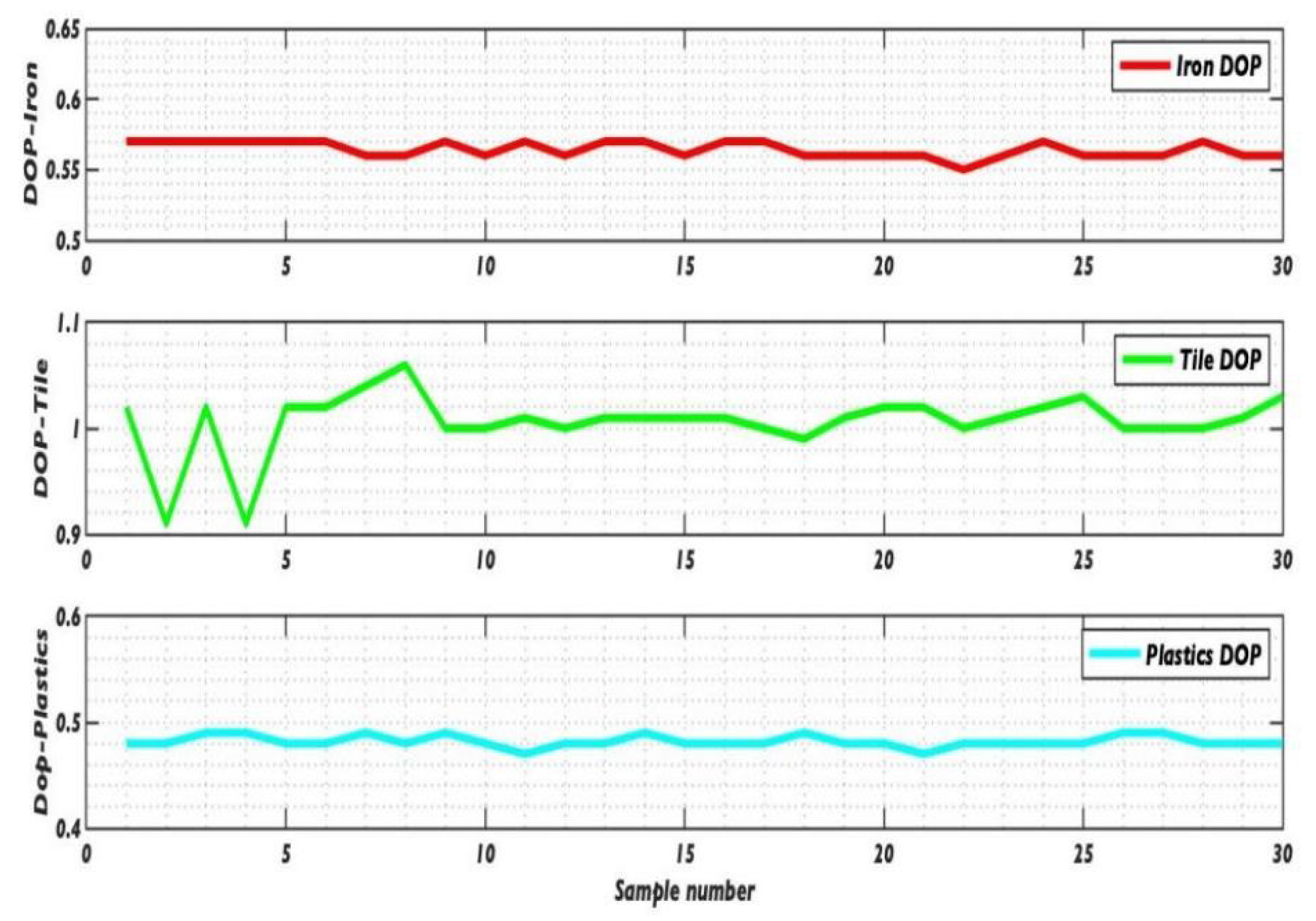
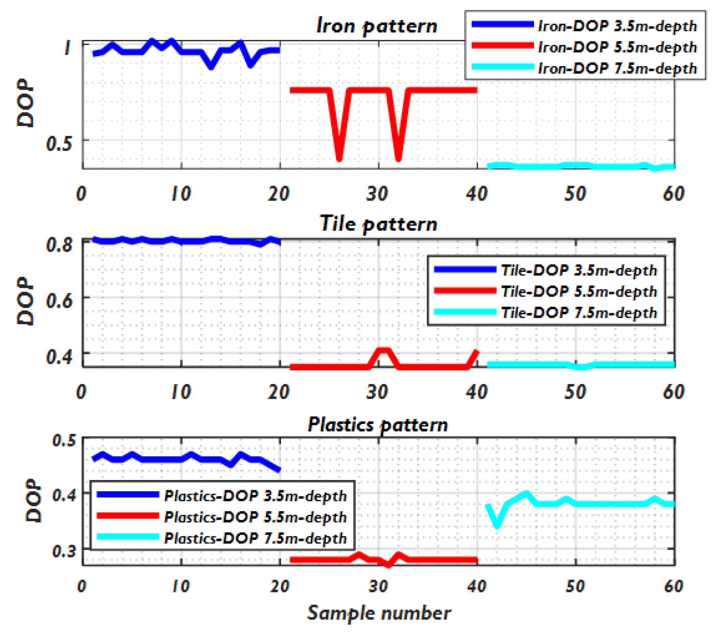
4.2. Effect of Different Objects on the Degree of Polarization under the Same Environment

The data collection conditions of the air experiment are as follows: different objects are placed in the air at a distance of 11 m to measure the polarization information of reflected light. Measurements are recorded for each object at each location. Use Equation (9) to calculate the degree of polarization of reflected light. The experimental data are shown in Table 2.
When testing in the air, placing different targets on the platform, the laser scans one target after another and records the data in order to more clearly show the degree of polarization of an iron sheet, ceramic tile, plastic objects in the air DOP, the above-mentioned data were made into the broken line diagram of Figure 8, and the average degree of polarization of iron sheet was 0.564333333, ceramic tile was 1.0063333, and plastic was 0.48222222. The degree of polarization of ceramic tile is close to 1, but the degree of polarization of iron plate and plastic is small, being about 0.56 and 0.48, respectively, and can be divided according to this part of the material target.
The degree of polarization is as follows: ceramic tile DOP > Iron Sheet DOP > plastic DOP. The degree of polarization of reflected light will be higher for man-made targets due to the smooth surface, while the degree of polarization of ceramic tiles is the highest for both man-made targets. It shows that the degree of polarization is closely related to the material and the surface smoothness of the object.
The data collection conditions for the in-water experiment were as follows: different objects were placed in the water at distances of 3.5 m, 5.5 m, and 7.5 m, respectively, to measure the polarization information of reflected light, and the objects were selected in turn from three kinds of objects: iron, tile, and plastic. Measurement data were recorded for each object at each location. The polarization of the reflected light was calculated using Equation (9). The specific experimental data are shown in Table 3.
In the water test, in order to more clearly show the polarization of iron, tile and plastic three objects in the water DOP, the above data made the line graph in Figure 9. From the data analysis, the average polarization of iron in 3.5 m is 0.9655, in 5.5 m is 0.724, in 7.5 m is 0.3625, tile in 3.5 m. With the increase of water depth, the polarization of the object gradually decreases.
The relationship between the magnitude of polarization is iron DOP > tile DOP > plastic DOP. The polarization of the same object at different water depths will also change. It can be seen that the polarization of reflected light will be higher for man-made targets due to the smooth surface, while the polarization of iron is the highest for the same man-made targets, indicating that the polarization is indeed closely related to the target material and the flatness of the object surface, so it is possible to distinguish different objects according to their reflected light The polarization of the object can therefore be distinguished from different targets according to the polarization of the reflected light. In the multiple measurements of the data, it can be seen that the calculated polarization has deviation, and reviewing the experimental method, the error should be caused by the fluctuation of the water body and other stray noise, and the accuracy of the detection system and the consistency of the measurement still need to be improved.

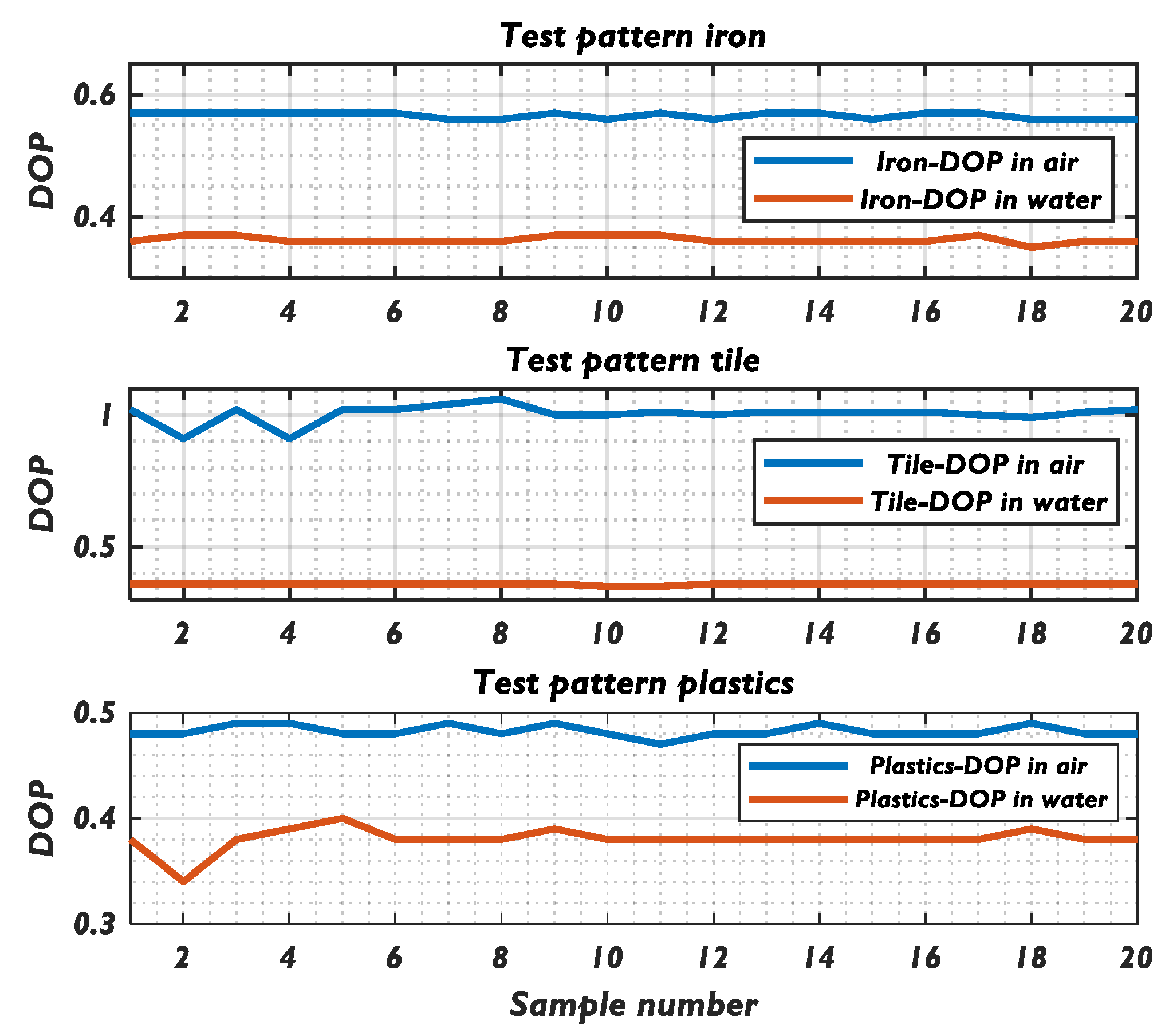
4.3. The Influence of the Same Object on the Degree of Polarization in Different Environments

In order to more clearly show the polarization DOP comparison of three objects, iron, tile and plastic, in air and water, the data in Table 2 and Table 3 were made into the line graph in Figure 10. It can be seen that in air, the average polarization of iron is 0.56, tile is 1.00, and plastic is 0.48; in water, the average polarization of iron at 7.5 m is 0.3625, tile at 7.5 m is 0.359, and plastic at 7.5 m is 0.3805. The polarization intensity of the tile in air is the largest, but it is not as strong as that of the iron in water. However, in water is not as good as iron, taking into account the absorption of light and water fluctuations and other miscellaneous wave effects, and the polarization of various types of targets in air is significantly greater than the polarization of targets in water, the material of the target material and the smoothness of the surface has a greater impact on the polarization.

5. Conclusions

Through the above test data, the results show that in the air tile DOP > iron DOP > plastic DOP, tile in the three target materials can reach a maximum polarization of 1.00, iron and plastic average polarization of 0.56 and 0.48. In the water at 3 m, the polarization of different materials varies greatly, with iron, tile and plastic polarization of 0.97, 0.80 and 0.46. However, with the increase in distance, all objects are close to the polarization of about 0.36. This phenomenon may be due to the experiments used in the pool being relatively narrow; the distance gradually increased, the laser by the body of water and the wall of the pool many times the reflection level scattering, causing the final recession effect to be relatively close. In addition, at a closer distance, the main factor causing the change in polarization to the polarization characteristics of the target reflection, so at a closer distance, the polarization of the reflected light varies greatly.
For underwater target detection, polarization detection can obtain rich information and less interference. Compared with other polarization detection experiments, we measured that the polarization of different materials at different depths will change after laser reflection, taking into account the influence of material properties, materials and clutter, but there are more factors that cause the change of polarization, in some fixed conditions, it is possible to distinguish different targets by polarization. Due to the limitations of the test conditions, only a few characteristics of the distance can be tested during the in-water test, and the database composed of data samples is not yet able to accurately distinguish between different targets. To distinguish the targets more accurately, a large number of data tests on the target samples are needed to establish and improve the target polarization parameter database, and at the same time, repeated tests should be conducted in different experimental environments to verify the correctness of the test results.

Author Contributions

Conceptualization, Y.Z.; Methodology, Q.F.; Validation, J.L.; Investigation, C.D.; Data curation, J.D.; Writing—original draft, Q.H. All authors have read and agreed to the published version of the manuscript.

Funding

This research was funded by Changchun University of Science and Technology, China. Huilin Jiang, National Natural Science Foundation of China, grant number: 61890960, 61890963, JJKH20220744KJ, 62127813.

Institutional Review Board Statement

Not applicable.

Informed Consent Statement

Not applicable.

Data Availability Statement

The study did not report any data.

Conflicts of Interest

The authors declare no conflict of interest.

References

  1. Chen, Z.; Wang, H.; Shen, J.; Xu, L. Underwater target detection based on intensity-spectrum-polarization information fusion. J. Commun. 2013, 34, 7. [Google Scholar]
  2. Bao, F.; Duan, J.; Dong, S.; Ma, L.; Yu, T.; Zhan, J. Study on polarization imaging characteristics of underwater targets. J. Appl. Opt. 2019, 40, 27–32. [Google Scholar]
  3. Liu, F.; Sun, S.; Han, P.; Yang, K.; Shao, X. Research and development of underwater polarization imaging technology. Adv. Laser Optoelectron. 2021, 58, 18. [Google Scholar]
  4. Chiu, W.; Dai, H.; Shin, L.; Zhang, J. Overview of underwater polarization sharp imaging methods. Infrared Laser Eng. 2020, 49, 11. [Google Scholar]
  5. Li, Y.-C.; Wang, C.; An, Y.; Shao, Y.; Hu, Y. Research of laser and infrared polarization detection technology for underwater moving stealth target. Laser Infrared 2016, 46, 209–213. [Google Scholar]
  6. Yang, F.; Wang, C.; Pang, G.; Liu, H.F.; Wang, C.; Pang, G. Design of underwater detector optical system based on polarization technology. J. Chang. Univ. Sci. Technol. Nat. Sci. Ed. 2018, 41, 4. [Google Scholar]
  7. Wang, L. Polarization Imaging Detection of Underwater Target Based on Laser; Changchun University of Science and Technology: Changchun, China, 2019. [Google Scholar]
  8. Liu, X.; Wang, F. Research on detection method of camouflage target based on polarization characteristics. Opt. Technol. 2008, 34, 4. [Google Scholar]
  9. Cao, N. Quantitative Study of Improvements of the Imaging Contrast and Imaging Range by the Polarization Technique. Acta Phys. Sin. 2000, 49, 65–66. [Google Scholar]
  10. Xiang, Y. Maxwell's theory of electromagnetic fields. Physics 1991, 20, 6. [Google Scholar]
  11. Qin, Z.; Cheng, Z.; Zhang, Z.; Zhu, J. High-speed real-time measurement of polarized light Sir George Stokes, 1st Baronet Parameters. J. Opt. 2007, 27, 4. [Google Scholar]
  12. Kong, W.; Li, G. Using Stokes vector and Muller matrix to determine the ratio of azimuth to major axis of elliptically polarized light. Appl. Opt. 2002, 23, 3. [Google Scholar]
  13. Sun, X.; Lee, H.; Tang, L. Study on polarization degree of visible and infrared light scattering from atmosphere. J. Opt. 2011, 31, 6. [Google Scholar]
Figure 1. Principle diagram of polarization measurement.
Applsci 13 03222 g001
Figure 2. Schematic diagram of pulse ranging.
Applsci 13 03222 g002
Figure 3. Hardware connection diagram and system experiment schematic diagram.
Applsci 13 03222 g003
Figure 4. Experimental setup for measuring polarization characteristics in air.
Applsci 13 03222 g004
Figure 5. Experimental setup for measuring polarization characteristics under water.
Applsci 13 03222 g005
Figure 6. Structure diagram of simulated pool body.
Applsci 13 03222 g006
Figure 7. Energy contrast diagram of four probes, (a) is a plan and (b) is a three-dimensional diagram.
Applsci 13 03222 g007
Figure 8. A comparison of the degree of polarization of different objects in the air.
Applsci 13 03222 g008
Figure 9. Comparison of the degree of polarization of different objects at different depths in water.
Applsci 13 03222 g009
Figure 10. The degree of polarization of the same object in air and water.
Applsci 13 03222 g010
Table 1. A summary of the consistency of the four probe measurements.
Energy Point (J)Probe 1Probe 2Probe 3Probe 4Inconsistency
2.93 × 10−123.12 × 10−123.02 × 10−123.12 × 10−122.97 × 10⁻¹²±2.5%
5.85 × 10−125.94 × 10−125.81 × 10−126.06 × 10−125.85 × 10⁻¹²±2.1%
2.34 × 10−112.35 × 10−112.28 × 10−112.30 × 10−112.25 × 10⁻¹¹±3.1%
1.42 × 10−101.42 × 10−101.39 × 10−101.43 × 10−101.43 × 10⁻¹⁰±1.4%
3.47 × 10−103.54 × 10−103.48 × 10−103.47 × 10−103.40 × 10⁻¹⁰±2.0%
1.28 × 10−91.31 × 10−91.25 × 10−91.28 × 10−91.28 × 10⁻⁹±2.4%
3.16 × 10−93.17 × 10−93.07 × 10−93.10 × 10−93.03 × 10⁻⁹±2.3%
6.77 × 10−97.17 × 10−97.00 × 10−97.16 × 10−97.19 × 10⁻⁹±1.4%
Measurement inconsistency: measured with four probes at the same energy point, the maximum deviation of the four measurements divided by two times the average of the four measurements.
Table 2. Test raw data after reflection of different targets in the air.
Serial
Number
Distance (m)0° (J)45° (J)90° (J)135° (J)IQUDOPAop
1 (Iron)11.0291.83× 10−99.7 × 10−102.48 × 10−93.34 × 10−94.31 × 10⁻⁹−6.43 × 10⁻¹⁰−2.37 × 10−90.5737.40
2 (Iron)11.0291.76 × 10−99.3 × 10−102.37 × 10−93.19 × 10−94.13 × 10⁻⁹−6.11 × 10⁻¹⁰−2.26 × 10−90.5737.43
3 (Iron)11.0291.66 × 10−98.75 × 10−102.23 × 10−93 × 10−93.88 × 10⁻⁹−5.68 × 10⁻¹⁰−2.13 × 10−90.5737.52
4 (Tiles)11.0337.01 × 10−113.3 × 10−111.98 × 10−102.45 × 10−102.73 × 10⁻¹⁰−1.28 × 10⁻¹⁰−2.12 × 10−100.9129.48
5 (Tiles)11.0336.07 × 10−112.92 × 10−117.43 × 10−112.3 × 10−101.97 × 10⁻¹⁰−1.36 × 10⁻¹¹−2.01 × 10−101.0243.07
6 (Tiles)11.0346 × 10−112.87 × 10−117.35 × 10−112.28 × 10−101.95 × 10⁻¹⁰−1.35 × 10⁻¹¹−1.99 × 10−101.0243.07
7 (plastic)11.0332.48 × 10−102.42 × 10−103.76 × 10−105.65 × 10−107.15 × 10⁻¹⁰−1.28 × 10⁻¹⁰−3.23 × 10−100.4934.16
8 (plastic)11.0342.48 × 10−102.44 × 10−103.78 × 10−105.66 × 10−107.18 × 10⁻¹⁰−1.29 × 10⁻¹⁰−3.22 × 10−100.4834.05
9 (plastic)11.0332.66 × 10−102.52 × 10−103.97 × 10−105.97 × 10−107.57 × 10⁻¹⁰−1.30 × 10⁻¹⁰−3.45 × 10−100.4934.64
Table 3. Raw data of different underwater targets after reflection test.
Serial NumberDistance (m)0° (J)45° (J)90° (J)135° (J)IQUDOPAOP
1 (Iron)3.5586.85 × 10−113.19 × 10−118.2 × 10−112.2368 × 10−102.03 × 10⁻¹⁰−1.35 × 10⁻¹¹−1.92 × 10−100.9542.99
2 (Iron)3.5586.67 × 10−113.08 × 10−117.97 × 10−112.2157 × 10−101.99 × 10⁻¹⁰−1.30 × 10⁻¹¹−1.91 × 10−100.9643.05
3 (Iron)3.5575.81 × 10−112.72 × 10−117.1 × 10−112.1121 × 10−101.84 × 10⁻¹⁰−1.29 × 10⁻¹¹−1.84 × 10−101.0043.00
4 (Tiles)3.4751.08 × 10−105.28 × 10−112.43 × 10−103.04 × 10−103.54 × 10⁻¹⁰−1.35 × 10⁻¹⁰−2.51 × 10−100.8130.91
5 (Tiles)3.4751.12 × 10−105.52 × 10−112.48 × 10−103.12 × 10−103.64 × 10⁻¹⁰−1.36 × 10⁻¹⁰−2.57 × 10−100.8031.08
6 (Tiles)3.4751.09 × 10−105.27 × 10−112.44 × 10−103.04 × 10−103.55 × 10⁻¹⁰−1.36 × 10⁻¹⁰−2.52 × 10−100.8130.83
7 (plastic)3.3517.3 × 10−104.59 × 10−107.84 × 10−101.19 × 10−91.58 × 10−9−5.40 × 10⁻¹¹−7.28 × 10−100.4642.88
8 (plastic)3.3517.09 × 10−104.55 × 10−107.66 × 10−101.16 × 10−91.55 × 10−9−5.75 × 10⁻¹¹−7.06 × 10−100.4642.67
9 (plastic)3.3517.6 × 10−104.77 × 10−108.18 × 10−101.24 × 10−91.65 × 10−9−5.83 × 10⁻¹¹−7.64 × 10−100.4642.82
Disclaimer/Publisher’s Note: The statements, opinions and data contained in all publications are solely those of the individual author(s) and contributor(s) and not of MDPI and/or the editor(s). MDPI and/or the editor(s) disclaim responsibility for any injury to people or property resulting from any ideas, methods, instructions or products referred to in the content.

