1. Introduction
The basic concepts and techniques of fault tolerance in computer systems were described in [
1], which presented the different error classifications and the application of redundancy techniques to ensure the reliable operation of computers. The modeling and prediction of faults were also described, along with examples of fault-tolerant computers. In the early 1990s, Stengel [
2], Veillette [
3], and Patton [
4] published the results of different applications of FTC systems. In [
5], state-of-the-art methods for fault-tolerant control applications up until 1997 were presented.
In a fault-tolerant control system, it is necessary to distinguish concepts such as fault definition and fault tolerance. A fault is defined as the deviation of a parameter from an acceptable value. Fault tolerance is the ability of the system to continue operation regardless of faults. The origins of FTC systems are related to the need to use special control in critical safety devices and equipment. Examples of such devices are aircraft or nuclear power plants. In [
6], which was published in 1990, one of the first applications of fault-tolerant control in robot manipulators was described and the measure of joint failure influences on the remaining dexterity of a kinematically redundant manipulator was quantified. This measure was used as a criterion and technique for calculating optimal configurations of fault-tolerant redundant manipulators. An example of a three-dimensional robot was shown that used a fourth actuator, which guaranteed half of the original dexterity, after the joint failure.
In the same period, i.e., in the 1990s, extensive research was undertaken to develop FTC systems for applications in manipulators intended for space research [
7,
8,
9]. The foundations for the design of fault-tolerant manipulators were presented in [
10]. In this article, the modeling tools and reliable evaluation methods of robots were described. The design aspects, together with a reliability evaluation, were presented. Based on the performed analyses, a methodology for designing fault-tolerant manipulators was proposed. Particular attention was paid to the development of recommendations for the design of the arm with 10 degrees of freedom. It was proposed to use two actuators on each joint.
Techniques for a robust residual generation have been proposed by several authors. In order to ensure the successful operation of autonomous robots in remote or hazardous environments, fault tolerance is essential. In [
11], different fault tolerance algorithms were proposed, where the possible failures of the robot components and the interdependence of these failures must be determined first. To achieve this, fault tree analysis can be a very useful tool. The tree structures developed using this type of analysis make it possible to both determine a block diagram of possible occurrences of robot faults and define the cause-and-effect relationships between failures.
In [
12], a control method was proposed in which a model reference algorithm and a proportional integral derivative controller were applied in the fault-tolerant operation of robotic manipulators. This method was tested in a simulation that showed the effectiveness of the recovery algorithm, which enabled it to continue the movement on the assumed trajectory and reach the given end effect.
In 1987, Selkäinaho and Halme [
13] proposed the use of artificial intelligence, i.e., a real-time expert system, in a fault control solution, which was used in an algorithm to supervise fault detection and localization. In the case of sensor damage, the system automatically replaced the faulty measurement with an updated predictor model output signal. The investigated system was successfully tested in a pilot process using artificial intelligence to overcome physical faults.
The authors of [
14] proposed the use of intelligent fault-tolerant control in a flexible assembly cell, where the fault-tolerant controller would immediately recognize errors and react in real time to such situations. In the described solution, the combination of an advanced autonomous supervision system was combined with a sensor-guided action generator. Experimental tests were conducted using a mobile two-arm robot system.
Groom et al. [
15] described the real-time fault-tolerant control developed for a kinematically redundant manipulator. The authors used a fault-tolerance measure to enable the end effector of the manipulator to continuously follow a given trajectory. Finally, an algorithm was developed and used in real time for the control of a seven-degree-of-freedom commercially available manipulator.
The purpose of using FTC systems is to assure reliability, which should be maintained despite the occurrence of faults of an acceptable nature. Intensive work is currently underway to develop this type of control in equipment used during manufacturing processes. One of the advantages of using this type of control in the production process is not only the safety of critical equipment but also cost reduction. The reduction in production costs is influenced by the continued operation of the devices used. At the time of an acceptable FTC failure, there is no need to stop production for maintenance purposes. This results in a reduction in the costs associated with service calls and also saves time by preventing a halt in the production process.
Shin and Lee [
16] presented a robust fault-tolerant control system, which can be used to overcome the failure of the robot manipulator actuators. The controller uses the algorithms for normal control (non-failed), fault detection, and control in case of faults to achieve the assumed task completion.
Fault-tolerant control systems can be divided into three main categories: passive FTCS (PFTCS), active FTCS (AFTCS), and hybrid FTCS (HFTCS). PFTCS are characterized by the fact that they operate offline and are only able to adapt to faults that are defined at the design stage. Passive fault-tolerant steer systems do not require fault detection and isolation and are less computationally complex than active systems. AFTCS consist of a reconfiguration mechanism and a fault defection identification (FDI) mechanism. The FDI subsystem provides information to the controller about the fault and the controller responds by reconfiguring itself or the controlled device. The FDI subsystem is a key component of an active FTCS as it detects the fault and immediately sends information to the controller. The immediate reconfiguration of the controller upon receiving information from the FDI allows this method to be called active. There are also hybrid HFTCS controllers, which are a combination of PFTCS and AFTCS.
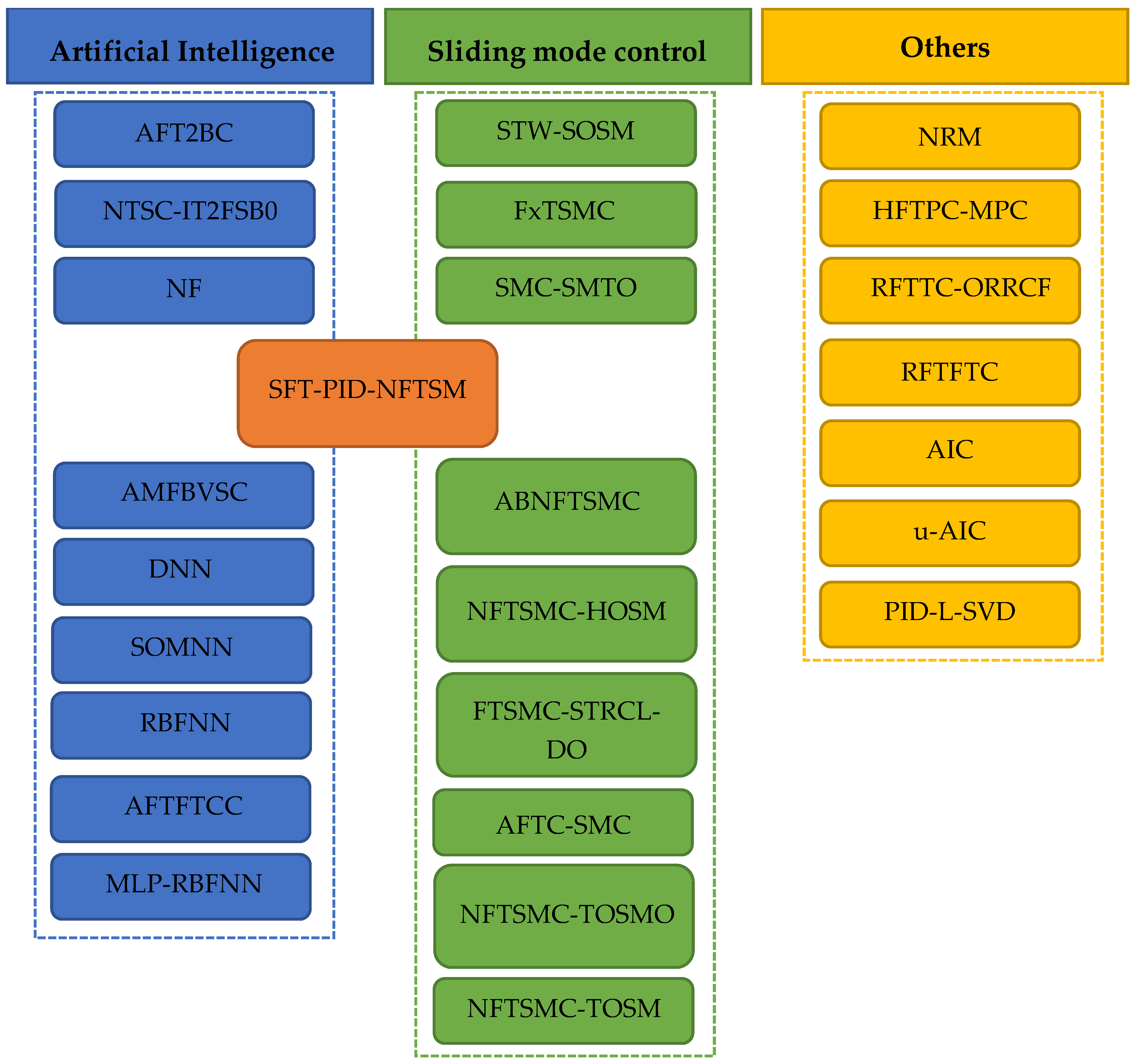
In this paper, all the above-mentioned methods used in applications for robotic arm steering are reviewed. The methodology for selecting articles for this paper was limited to the time frame of the proposed solutions, that is, mainly the last 20 years. In addition, it was decided to place the main emphasis only on solutions that use artificial intelligence and sliding-mode controllers. Furthermore, all the selected papers deal with the use of FTC methods in robot control. In addition, the papers that focus on the control of manipulators with up to 7 degrees of freedom were chosen for our review. Articles about other robots such as hexapods or mobile robots were excluded from this review. This review is presented in six chapters, covering the available solutions of various FTC systems used to control robotic arms. In
Section 1, the history and background of FTC systems are described.
Section 2 is devoted to presenting the state-of-the-art FTCS that use artificial intelligence methods.
Section 3 presents the variants of FTCS that use sliding-mode control.
Section 4 deals with other FTCS used in robots that have been developed in recent years.
Section 5 presents the summary and
Section 6 presents the conclusions.
2. Artificial Intelligence Methods in FTCS
Artificial intelligence methods are highly developed techniques that have applications in fault-tolerant strategies for controlling robotic arms. Among the artificial intelligence methods used for fault-tolerant control systems are fuzzy logic controllers, which are able to effectively deal with non-linear systems using membership functions, which assess analog input signals using logical variables that take values between 0 and 1. The authors of [
17] described the so-called adaptive fuzzy type-2 backstepping control (AFT2BC) method. The backstepping method was also described in [
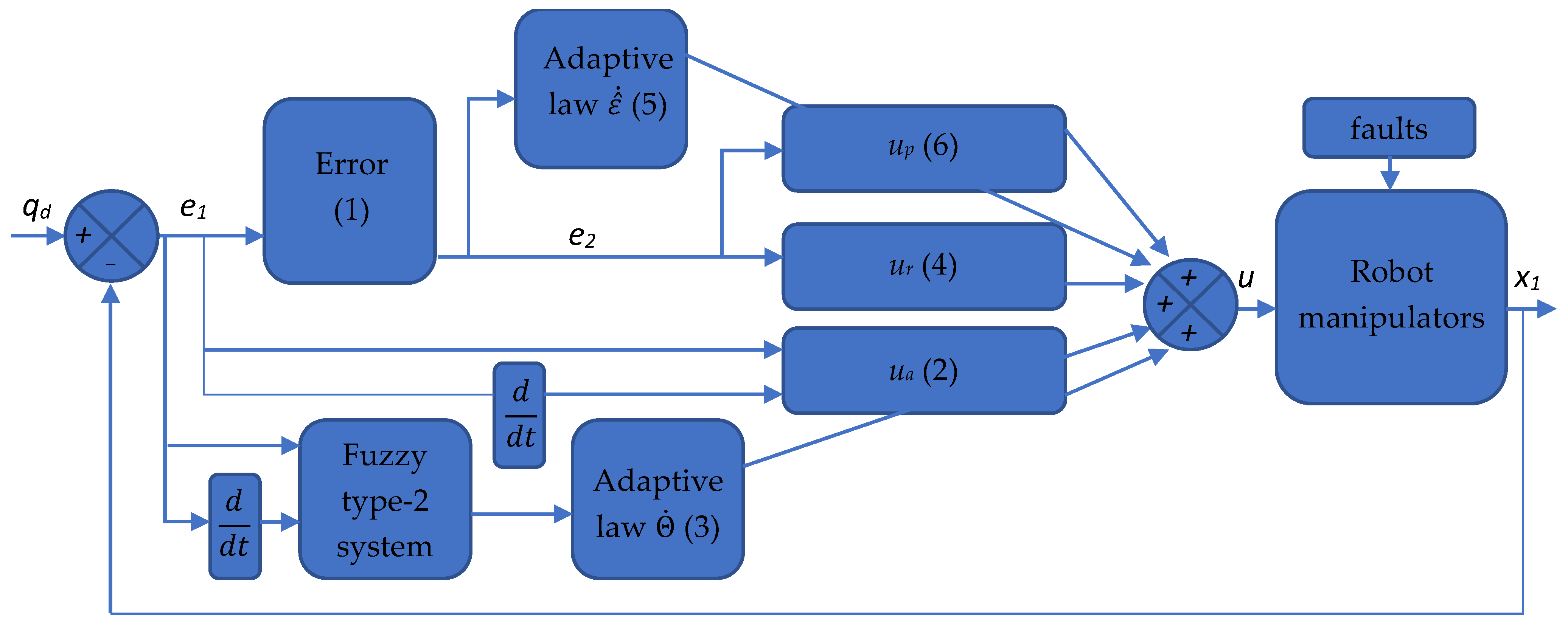
18]. AFT2BC was tested on a model of a PUMA560 robotic arm in a MATLAB environment in which the kinematic configuration of the robot could be changed simultaneously to simulate axis failure and changes in the load on the arm. The proposed control algorithm did not require a priori knowledge of the dynamic robot model so the controller could operate when the faulty condition was due to both model uncertainty and external disturbances.
Figure 1 shows a block scheme of the proposed adaptive control method. On the description of the graph is a set of Lyapunov Equations (1)–(6) [
17]:
where
is the derivative of the Lyapunov function [
19],
is the tracking error,
is the derivative of the desired signal,
is the vector of the current state
,
,
where
is the fuzzy type-2 adaptive control expression that is designed to estimate the ideal backstepping control law,
represents the average basis functions obtained by a fuzzy type-2 system, where each basis function is given by the average of the corresponding left and right basis functions,
denotes the adapted vector parameters,
where
,
,
,
is a positive constant vector,
,
where
is the robust control expression that is introduced to reduce the effects of fuzzy type-2 estimation errors,
where
are parameters,
where
The authors of [
20] presented a fault-tolerant control scheme in the form of non-singular terminal synergetic control (NTSC) combined with interval type-2 fuzzy satin bowerbird optimization (IT2FSBO). The paper also described an adaptive augmented extended Kalman filter (A-AEKF) that detected, identified, and isolated actuator faults, even in the presence of noise [
21].
The authors of [
22] presented a neuro-fuzzy (NF) robot fault-detection algorithm that allowed for the control of a robot with an SRI [
23] controller despite sensor or axis actuator failures. The detection and fault-tolerance architecture of the proposed solution was built with a multilayer perceptron trained with the backpropagation of errors and a fuzzy logic block. The input layer of the artificial neural network consisted of 15 neurons organized into 3 groups, each consisting of 5 neurons, 1 for each axis. The three groups were used in turn for the preliminary assessment of the position, velocity, and acceleration. The network had two groups of output neurons, each with five neurons, one for each axis. These groups generated the positions and velocities for each axis in turn. The results of the multilayer perceptron (MLP) in the form of the product of the position and velocity, i.e.,
was summed with the output parameters of the robot. This sum was sent to the inference block, along with the results of the fuzzy logic block. The inference block receiving the data provided information about the axis that was damaged. The algorithm was successfully tested on a simulation of the ER5u robot in a MATLAB environment.
The authors of [
24] presented a system in which an artificial neural network in the form of a multilayer perceptron (MLP) was responsible for monitoring and fault detection (FD). This system consisted of a block in which the MLP provided information about the system failure while the fuzzy logic rule base made decisions about the type of fault and its location. The authors demonstrated the performance of fault detection based on a neuro-fuzzy (NF) application for a robotic arm with 5 degrees of freedom when one of the robot’s axes fails. The architecture of the system was similar to the solution described in [
23] but in this solution, the inference by the fuzzy logic system was based on the output of the neural network.
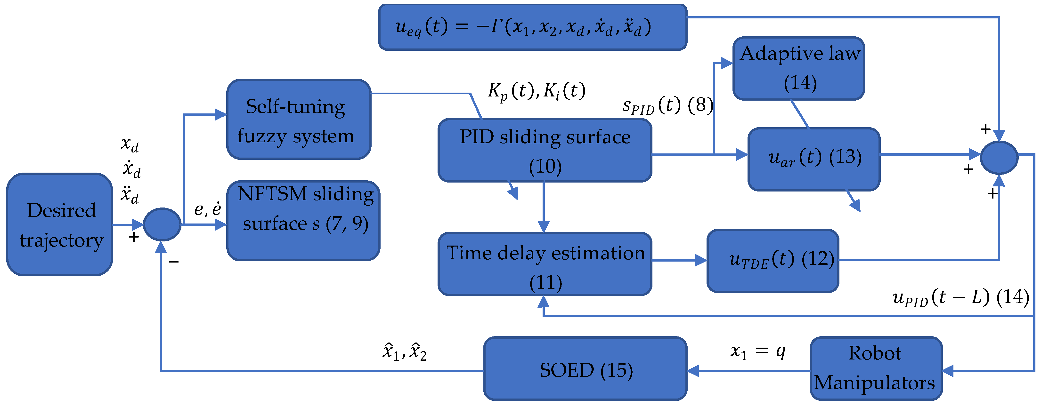
The authors of [
25] proposed a new solution in the form of self-tuning fuzzy proportional–integral–derivative non-singular fast terminal sliding-mode control (SFT-PID-NFTSM) with time delay estimation (TDE). The proposed method involved the self-tuning of the proportional–integral–derivative (PID) block of the controller using fuzzy logic algorithms. Compared to other well-known methods described in the literature, such as the PID controller or the controller with a fuzzy logic block responsible for the self-tuning of the PID block, i.e., (PID-NFTSM), the results of [
25] showed that the controller proposed in this work was more stable, had less overshoot, and improved transient responses. In addition, the integration of TDE reduced the required computational power of the controller and also helped to eliminate the requirement to know the exact dynamics of the system. The architecture of this system is shown in
Figure 2. In order to fully understand the operation of the presented architecture, it is necessary to explain Formulas (7)–(15), which underpin the system [
25]:
where s is the NFTSM sliding surface, e is the error,
and
are two positive definite matrices, p and q are two positive odd numbers selected to satisfy the conditions
,
where
is the sliding surface based on PID-NFTSM,
,
are the proportional, integral, and derivative gains,
where
are the state variables,
is the disturbance torque,
is a constant,
covers all the effects of the uncertainties, disturbances, and faults,
where
is a constant,
where
is the unknown function,
is the time delay,
where
is the estimation of the unknown function,
where
is the adaptive law,
K is an unknown constant,
is the estimation of the bounded value
K,
where
is the controller output signal,
is a lumped unknown function,
where
is the Lyapunov function,
is the adaption error, and
C is the adaption gain.
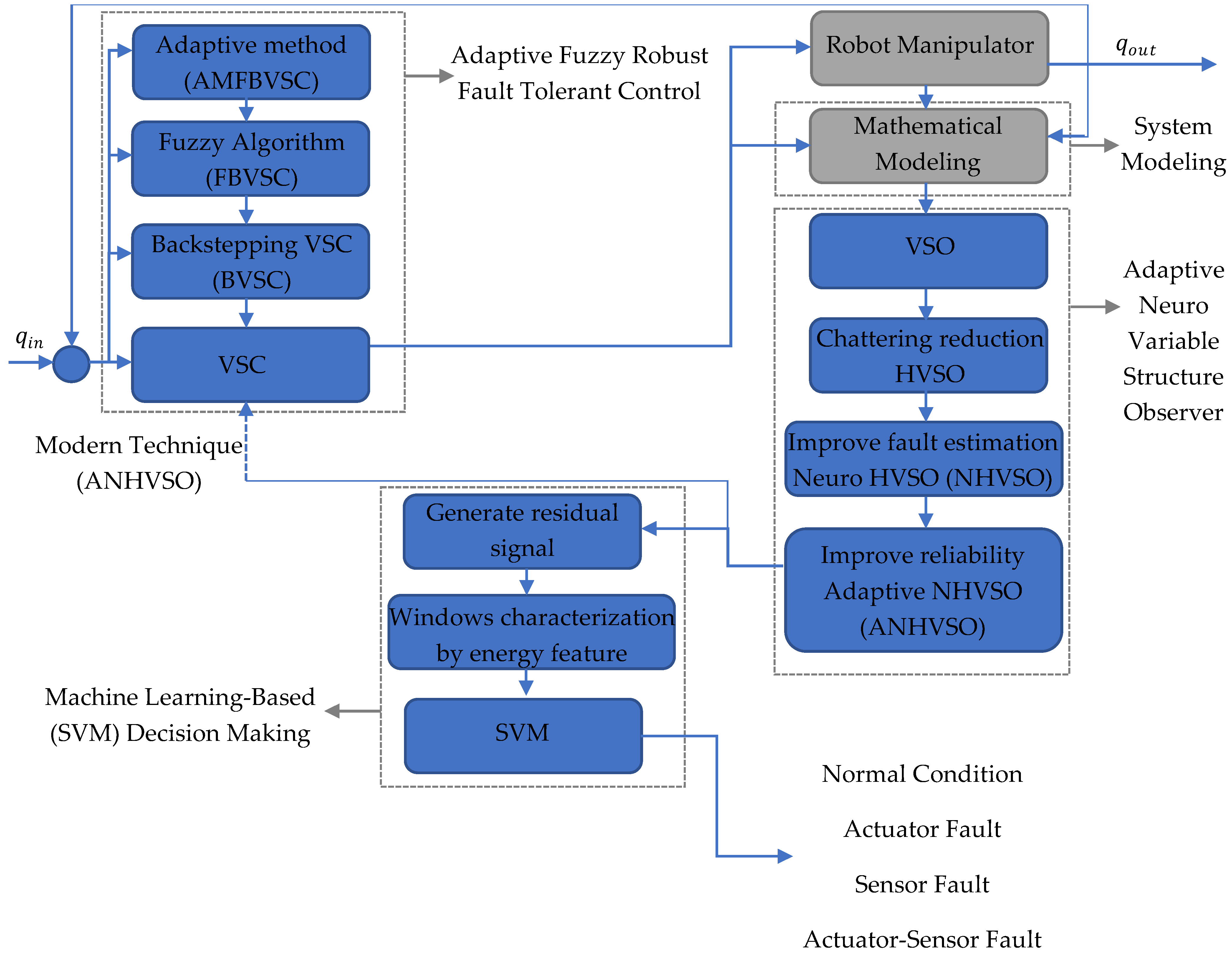
The authors of [
26] presented a new method of fault diagnosis and fault-tolerant control for a manipulator using a combination of a support vector machine (SVM)-based neural adaptive high-order variable structure observer (ANHWSO) and an adaptive modern fuzzy backstepping variable structure controller (AMFBVSC). The architecture of this control system is shown in
Figure 3. An SVM machine learning technique was used in this method for error detection and identification and the control process was based on AMFBVSC. The proposed control method, i.e., ANHVSO, improved the performance of fault identification significantly compared to the neural high-order variable, structure observer (NHVSO), and variable structure observer VSO. The work described in [
26] is another example of the application of artificial intelligence methods in fault identification. In this case, neural networks and machine learning were used in control, where fuzzy logic was used to tune the proposed method.
In [
27], the authors proposed the use of a dual neural network (DNN) [
28] for fault diagnosis and fault tolerance. This was the first study found in the literature to present the possibility of controlling a redundant manipulator when more than two axes fail. The paper presented the realization of the task of chalking a circle when as many as three of the available seven axes fail at different time periods. Prior to this, the control task at the time of axis failure was to exclude a single axis or a single sensor.
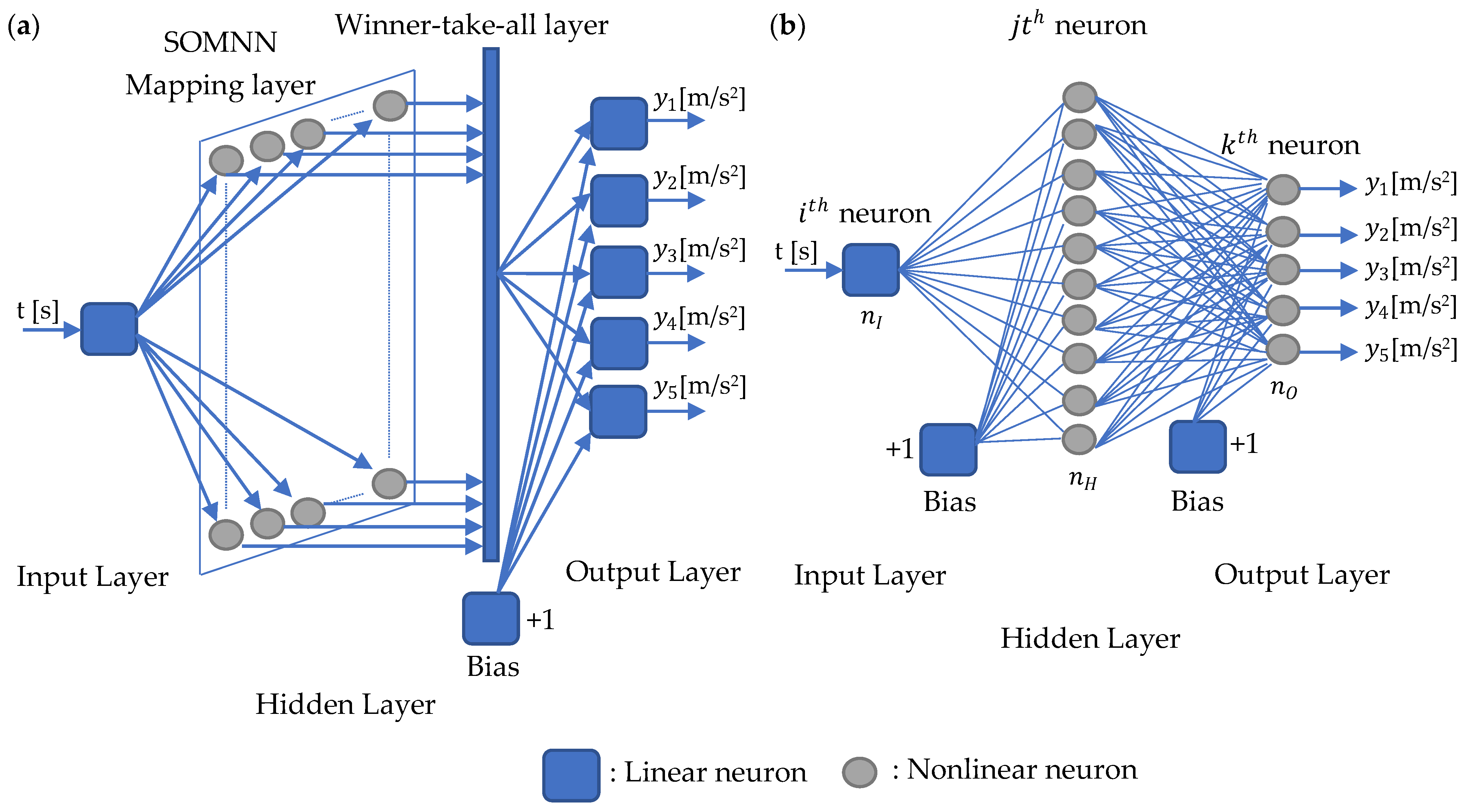
The authors of [
29] proposed and compared two approaches to FD error detection in a welding robot based on the prediction of accelerations of individual axes. The first acceleration prediction approach to fault detection was the use of a self-organizing map neural network (SOMNN). This network is shown in
Figure 4a. The second approach used a radial basis function neural network (RBFNN), which is shown in
Figure 4b. The paper demonstrated the feasibility of using RBFNN and SOMNN to predict the acceleration of individual axes for either detecting robot faults or predicting the remaining life of the device.
The authors of [
30] presented decentralized control strategies based on a radial basis function neural network (RBFNN). In this control method, each joint was treated as a separate subsystem. A fault in the joint was detected using a velocity observer. The presented law of adaptive control was based on information from individual joints. It can be applied to any robotic arm configuration.
The authors of [
31] proposed a radial basis function neural network (RBFNN) for estimating system failures in order to avoid a diagnostic error. The task of the neural network was to compensate for the external disturbances and actuator failures, which were recognized in the proposed method through an adaptive disturbance observer.
In [
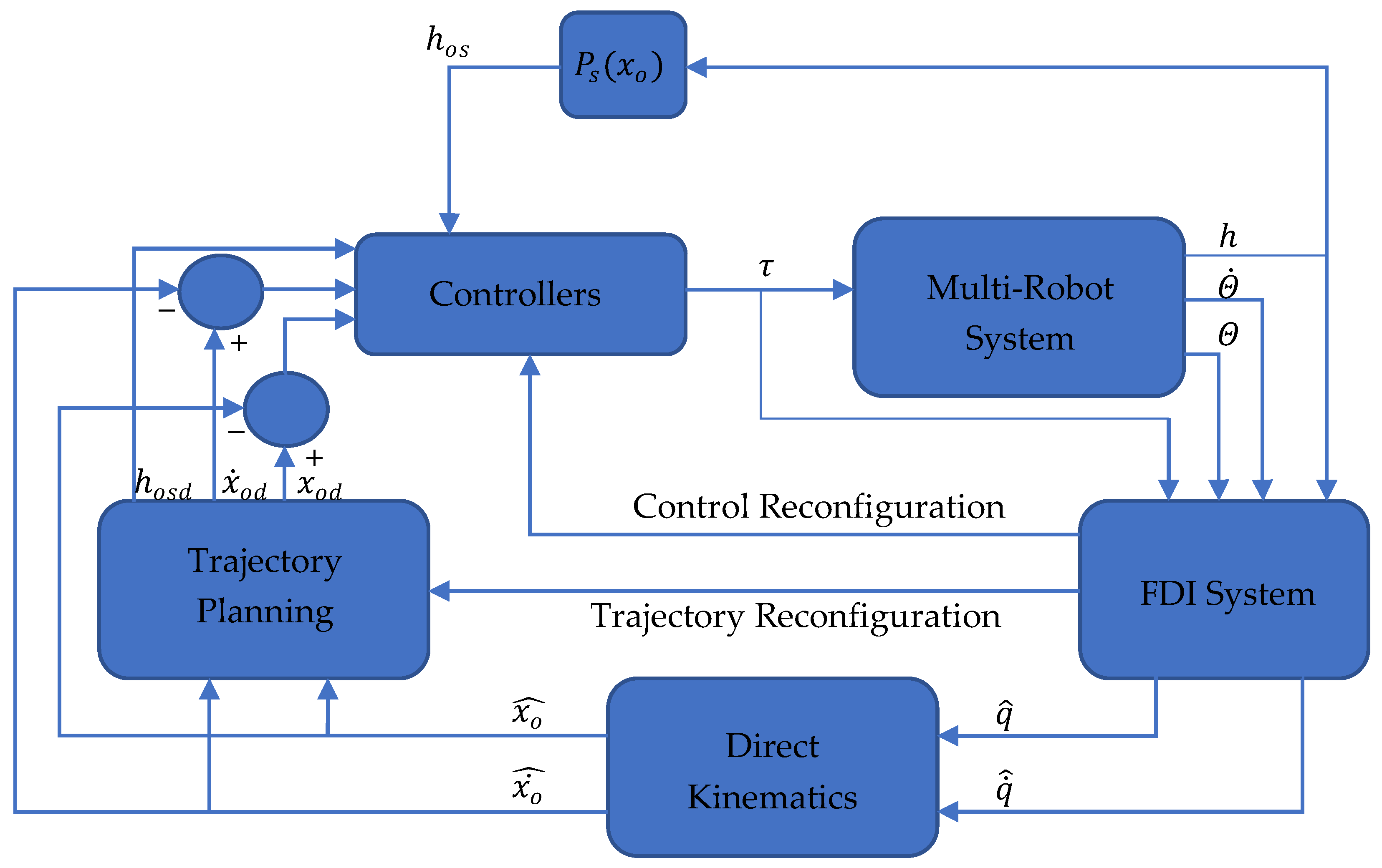
32], an adaptive fixed-time fault-tolerant constraint control (AFTFTCC) for trajectory tracking was proposed. The system was tested by the authors on two manipulators working together. The described method differs from other methods in that it does not need components such as a state estimator or a fault observer. The method used (RBFNN) to tease out the upper limit of uncertainty.
The authors of [
33] presented a control system that is robust to four types of faults: free-swinging joint faults, locked joint faults, incorrectly measured joint positions, and incorrectly measured joint velocities. Artificial neural networks in the form of MLPs and RBFNs were used to detect free-swinging defects and locked robot axes. The operation of neural networks in this solution was based on the detection of failures by the MLP, where each axis was represented by a separate MLP. The information in the form of a mapped error vector was then passed to the RBFNN, which used the vector to classify the error information. Due to the fact that the proposed control system detects the fault and then isolates it and reconfigures the controller, it was able to control the arm in case of multiple faults. However, this was not confirmed by tests in this work. The described control system is shown in
Figure 5.
3. Sliding-Mode Control in FTCS
One of the most popular methods used to control robotic arms is sliding-mode control (SMC). Sliding-mode control is based on variable structure systems consisting of independent structures with different properties and switching logic between them. In SMC, a discontinuous control signal, for example, +
k and −
k, are used, which forces the system to “slide” along the cross-section of the normal characteristics of the system. When a system moves along a curved or sliding surface, the system is said to be sliding. An up-to-date overview of all the available methods of control using the sliding mode was presented in [
34]. The simplest sliding-mode control method can be described by the formula:
where
u is the calculated signal,
k is a constant that is the magnitude of change,
e is the control signal error, and sign() is the sign function.
Equation (16) describes the simple sliding-mode control method. The advantage of this type of control is its simplicity and insensitivity to system uncertainty. Due to the fact that the method is discontinuous and most control systems are discrete, the main disadvantage of the presented method (16) is the system output signal oscillations called chattering. Nevertheless, the method has become attractive to researchers due to its simplicity; therefore, various sliding-mode control models are currently being designed and implemented for different objects. Due to its robustness to uncertainties, the SMC method is also often used in fault-tolerant control systems. It is applicable to manipulators for which fault tolerance is required.
One of the SMC fault-tolerant methods is the use of a sliding-mode observer (SMO) [
35] for fault detection. The use of a non-linear observer makes it possible to estimate the immeasurable state and model the uncertainty, which allows the construction of an error estimation algorithm.
In [
36], a fault-tolerant control system in the form of a super-twisting third-order sliding-mode (STW-TOSM) observer and a super-twisting second-order sliding mode (STW-SOSM) controller was presented. This method makes it possible to estimate errors and uncertainties without measuring the speed of the robot’s members. For the correct operation of the system, only position measurements are needed. In the paper, the authors presented a comparison of the following systems: the traditional computed torque controller (CTC) [
37], the active CTC-FTC controller [
38], the passive SM-FTC [
39] controller, and the proposed STW-SOSM-FTC controller in both passive and active forms. The test of the proposed controller showed fewer errors, better stability, and no vibrations on the obtained output waveforms. A block diagram of the arrangement of each block in the control process is presented in
Figure 6.
The authors of [
40] presented a system in the form of a fixed-time second-order sliding-mode observer (FxTSOSMO) and a fixed-time sliding-mode controller (FxTSMC). The work compared the proposed observer (FxTSOSMO) with the fixed-time sliding-mode observer (FxSMO) designed in an earlier work. The work compared the computed torque controller, non-singular fast terminal sliding-mode control (NFTSMC) controllers [
41], and the proposed method (FxTSMC). The latter system achieved higher estimation precision and the error of the proposed solution converged within a fixed time frame. The solution proposed in [
40] is described by the following Formulas (17)–(20):
where
is an approximate unknown component,
,
is a velocity error,
where
is the observer that was designed based on a super-twisting high-order sliding-mode algorithm,
,
is the inertia matrix,
,
v is the estimate of the velocity
,
,
,
where
is the proposed sliding surface,
,
where
u is the proposed controller output,
,
is the pseudo-inverse of the
,
,
,
is a positive constant,
.
The proposed algorithm was designed to follow a preset trajectory. The block for generating the preset trajectory is thus the first block of control. The signal from this block, together with the signal feedback from the FxTSOSMO block described by Equations (17) and (18), goes to the summing node. The feedback signal is the current positions and velocities. The position and velocity errors go from the summation node to the sliding surface block described by Equation (19). The signal s from the sliding surface block and ustw from the FxTSOSMO block go to the FxTSMC block described by the equation. The output of the FxTSMC block u described by Equation (20) goes to both the FxTSOSMO block and the robot. Finally, the FxTSOSMO block retrieves information about the robot in the form of positions and velocities.
In [
42,
43], the authors presented a fault-tolerant control system for a single-link flexible joint manipulator (SFJM). This work proved that it is possible to control the flexible coupling in a robot joint using SMC with SMTO. The presented results show that SMC is a method that can be applied to objects characterized by non-linearity and uncertainty. However, the presented solution was validated only for a single-axis manipulator, but it is possible to develop a similar system for a manipulator with more degrees of freedom.
The authors of [
44] proposed a novel methodology for manipulator adaptive backstepping non-singular fast terminal sliding-mode control (ABNFTSMC). The proposed approach combined NFTSMC with a backstepping design mechanism. The combination resulted in few tracking errors and low “chattering” on the output and provided fast response transients. The described system was compared to CTC, PID, PID-SMC, and NFTSMC controllers. The comparison of these systems showed improvements in the above-mentioned parameters.
In [
45], a system consisting of combined non-singular fast terminal sliding-mode control (NFTSMC) and a high-order sliding-mode (HOSM) controller was proposed. The presented control system also used an algorithm based on time delay estimation (TDE) for fault estimation. The results described in the work showed that fast terminal sliding-mode control (FTSMC) and NFTSMC systems have faster convergence compared to the non-singular terminal sliding-mode control method. FTSMC systems may encounter the problem of singularity during operation. However, the work shows the advantage of the NFTSMC system over the above-mentioned ones. Other methods using both active fault-tolerant control systems (AFTCS) and passive fault-tolerant control systems (PFTCS) were also rated in the paper.
In [
46], a combination of a controller in the form of non-singular fast terminal sliding-mode control (NFTSMC) with an observer in the form of third-order sliding mode (TOSM) was presented. The research results showed that the TOSM observer can estimate the speed of the system so that the system does not need to measure this. This method was compared with the SMC, NTSMC, and NFTSMC methods. The proposed NFTSMC method had the fewest trajectory-tracking errors. The TOSM observer, on the other hand, proved more accurate and had less “chattering” than the SOSM observer.
The authors of [
47] presented a combination of a fast terminal sliding-mode surface (FTSMS), super-twisted reaching control law (STRCL), and disturbance observer (DO). The proposed method was compared with the SMC and NFTSMC methods. The method described in the paper provided convergence in finite time and effectively combatted the chattering phenomenon. By using a disturbance observer, the complexity of the calculations was reduced. A DO was also used to estimate uncertainties in the form of dynamics, external disturbances, and failures. A diagram of the proposed method is shown in
Figure 7. This work presents the new fast terminal sliding surface described by the formula in [
47]:
where
is the FTSMS,
is an exponential function,
represents the positional control error,
represents the velocity control error,
are the positive constants,
,
,
where
is STRCL,
.
The authors of [
48] proposed a new sliding-mode control technique, namely active fault-tolerant control with synchronous sliding-mode control AFTC-SSMC. This control relied on the fact that with a traditional SMC controller, only the position error converges to zero. In synchronous control, on the other hand, both the position error and kinematic relationship between the errors converge to zero. The method was compared with standard active and passive sliding-mode control, namely AFTC-SMC and PFTC-SMC. It was shown that the pro-rated method had better fault tolerance and provided better trajectory-tracking performance.
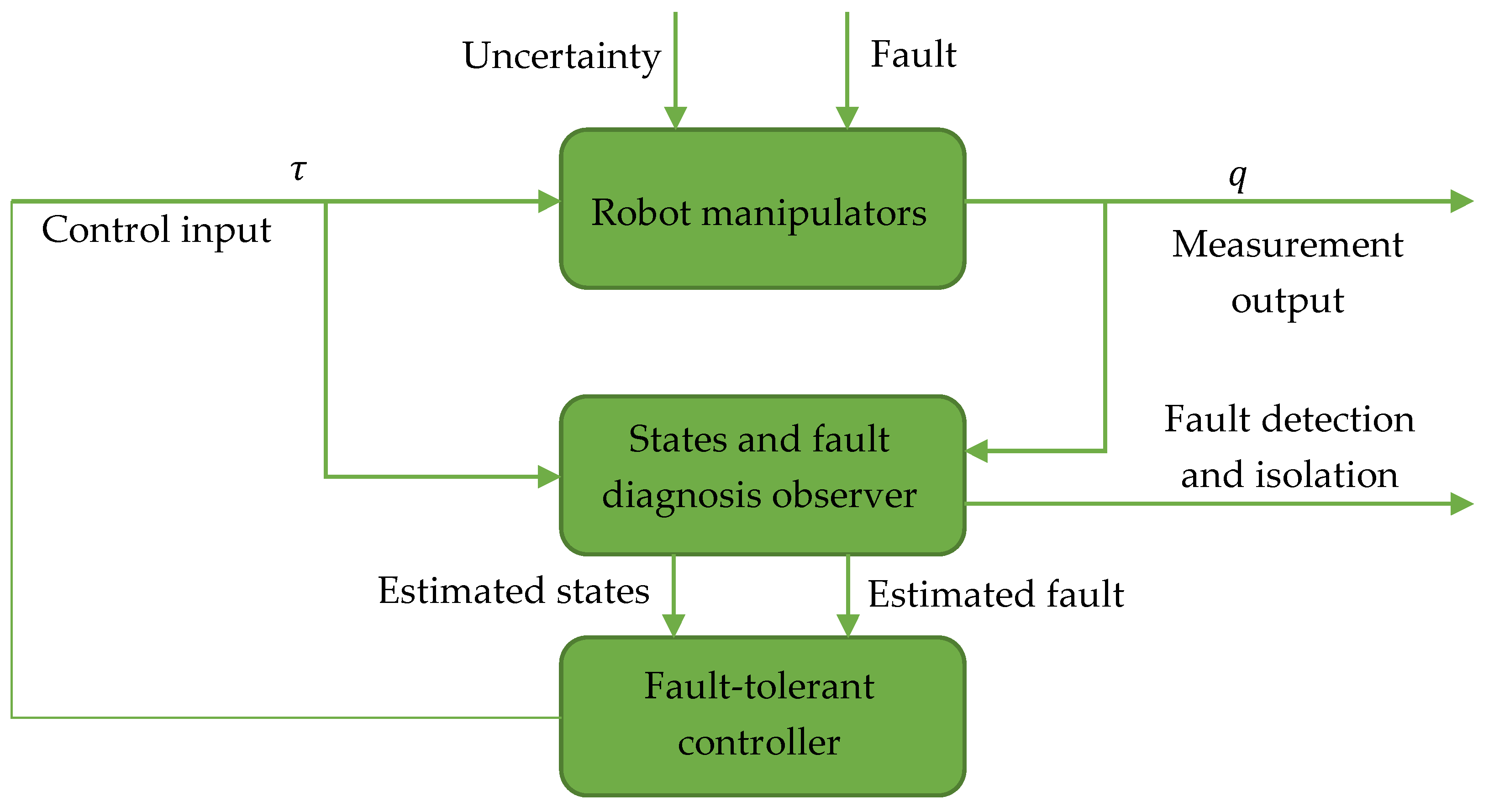
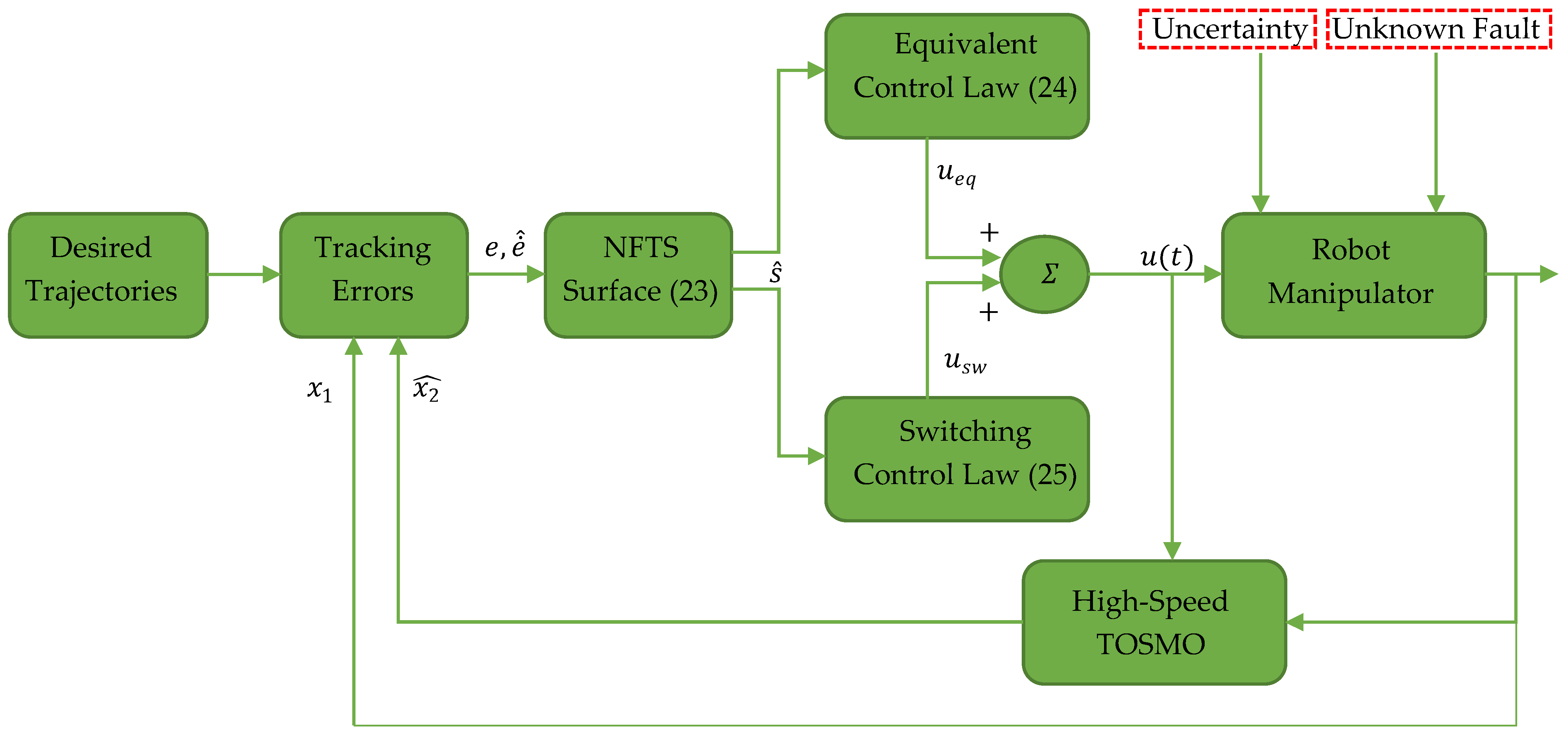
The authors of [
49] presented a fault-tolerant manipulator control strategy in the form of a combination of NFTSMC and the proposed high-speed third-order sliding-mode observer TOSMO. This combination was able to handle unknown input data, further reducing the vibration phenomenon and improving the accuracy of trajectory tracking. The proposed high-speed TOSMO could estimate both the velocity signal and input data faster than a standard TOSMO. The structure of such a system is similar to that of the FTSMS-STRCL-DO [
47] but it has a different observer model. The structure of the proposed method is shown in
Figure 8. The solution proposed by the authors is described by the following formulas [
49]:
where
is the NFTS surface,
are positive constants,
,
are constants,
where
is the equivalent control law,
,
is the nominal model of the robot manipulator,
is a positive constant,
denotes the sliding gains,
is an expected acceleration
where
is the switching control law,
is a small positive constant, and
is the estimation error as a positive value.
4. Other Robot-Dedicated FTCS
In addition to the leading fault-tolerant manipulator control methods such as SMC and artificial intelligence, other dedicated manipulator control methods can also be found in the literature. Some of them are presented in this section of the article.
The authors of [
50] presented the use of the well-known Newton–Raphson Method (NRM) [
51] to control a manipulator when a robot axis fails. The authors of this paper attached a QR code to the robot’s end arm. This code was read by a camera located at the base of the robot and then the position of the robot’s end was fed into the control software. This allowed the algorithm to determine the moment at which the failure occurred by not matching the position tracked by the camera with the calculated position. Then, the system, which used the Newton–Raphson method in the inverse kinematics calculation to find a good approximation for the root of a real-valued function, determined which joint had failed. To determine the faulty axis, the position measured by the camera was compared with the position calculated by the NRM. If a difference was detected, the system checked which axis was damaged. If a faulty joint was detected, the failed joint was treated as rigid and the robot’s inverse kinematics were recalculated using the Newton–Raphson method. Using this solution, the authors of the paper proved that if the robot was able to reach the set position despite the loss of an axis, the algorithm was able to help the robot achieve its goal.
In [
52], a new method of hybrid fault-tolerant predictive control (HFTPC) was proposed. This method was tested on a hybrid manipulator that was a combination of hydraulic and mechanical elements. The paper compared the proposed HFTPC method, one of the components of which was a predictive control (MPC) model [
53], with control in which only the MPC part was running. The presented system was able to control a hybrid manipulator when a failure occurred.
The authors of [
54] presented robust fault-tolerant tracking control (RFTTC) schemes for uncertain non-linear feedback systems (NFS) using operator theory-based robust right coprime factorization (ORRCF). It was shown that both RFTTC based on an internal model and RFTTC based on operator compensation were effective in dealing with interference and erroneous signals. The proposed system was tested on a trajectory-tracking task by a two-axis robot.
The authors of [
55] presented an adaptive fault-tolerant control system for unknown actuator faults. Detailed fault information was not required for the algorithm to work. The proposed method omitted complex logarithmic transformations in the pre-scribed performance control (PPC) structure [
56], making the controller efficient and simple to implement.
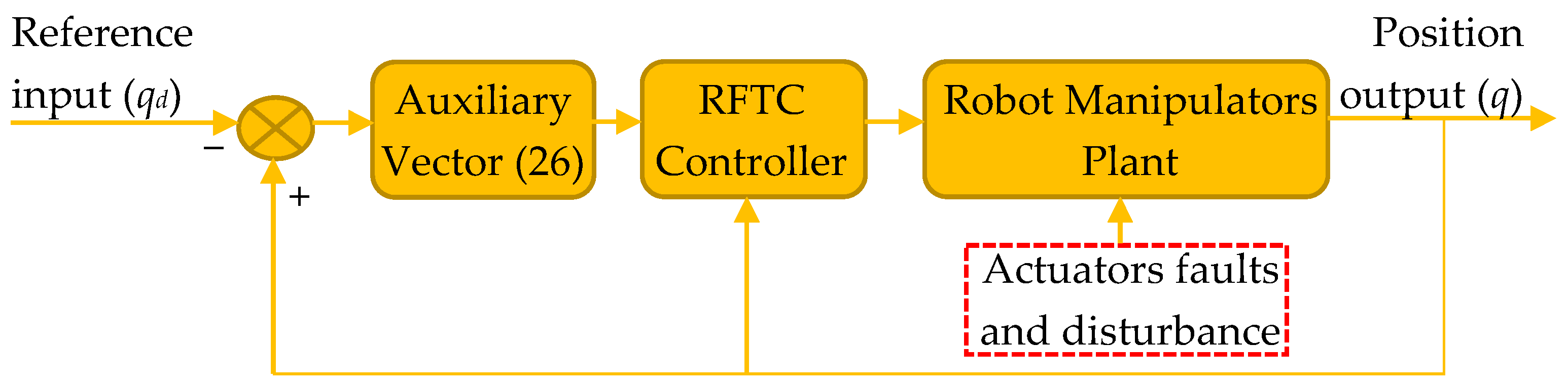
The authors of [
57] proposed a robust fixed-time fault-tolerant control system (RFTFTC) by introducing an additional auxiliary vector that was described by Formula (26) [
57]:
where
,
is the position error and
is the velocity error.
A schematic of the proposed system is shown in
Figure 9.
The authors of [
58,
59] presented an FTCS for manipulators based on an active inference controller (AIC). AIC makes use of the sensory prediction error in the free energy for the generation of residuals and thresholds for FDI. It does not require additional controllers for fault recovery. In [
59], the AIC was improved, and unbiased AIC (u-AIC) was introduced to reduce the probability of false positives and allow for the easy definition of probabilistically robust thresholds for fault detection.
The authors of [
43] presented fault-tolerant control using a proportional–integral–derivative (PID) controller. In addition to the PID controller, the system consisted of a Luenberger observer [
60], which was able to estimate the errors of the FDI analysis. From the information provided by the FDI, the magnitude of the error was evaluated using singular value decomposition (SVD) [
61]. The system in this solution was tested on a single-link flexible manipulator.
In earlier works, i.e., before 2019, the algorithms described in the literature for the control of robots in the case of communication faults dealt with two control types, i.e., state observers or estimators. The works in [
62,
63] presented a completely different approach to fault-tolerant control. The authors of these works dealt with a problem involving interference in the communication path through which information is sent between the robot’s actuators and the controller. The paper proposed to re-construct data corrupted during transmission using a splicing code. The transmission was carried out using the Controller Area Network (CAN) protocol [
64].
The authors of [
65] presented as many as four techniques for dealing with controlled oscillation and axis damage. These techniques were sinh-cosh, neural compensation, PID gain scheduling, and sinh-cosh gain scheduling. All of them were tested on a manipulator in which the failure was detected by measuring the currents through the robot axis drives. At the moment of axis failure, the current dropped to zero and then the axis was treated as passive, i.e., not participating in control. In the results of the paper, all four methods were compared. The comparison of the methods was conducted using a presentation of the trajectory-tracking error for each method. The best results in terms of the position errors of the individual axes were obtained for neural compensation, whereas the worst results were obtained by the sinh-cosh gain-scheduling method.


