Article

Features of the Internal Force Factors Distribution in Reinforced Concrete Piles of Complex Cross Section under the Influence of a Transverse Load

by
Albert Prokopov
1,
Alexander Akopyan
1,
Anton Chepurnenko
2,*,
Elizaveta Rusakova
3 and
Vladimir Akopyan
1
1
Engineering Geology, Bases and Foundations Department, Faculty of Civil and Industrial Engineering, Don State Technical University, 344003 Rostov-on-Don, Russia
2
Department of the Strength of Materials, Don State Technical University, 344003 Rostov-on-Don, Russia
3
Department of Physics, Don State Technical University, 344003 Rostov-on-Don, Russia
*
Author to whom correspondence should be addressed.
Appl. Sci. 2023, 13(4), 2673; https://doi.org/10.3390/app13042673
Submission received: 11 January 2023 / Revised: 8 February 2023 / Accepted: 17 February 2023 / Published: 19 February 2023

Abstract

:
Bar reinforced concrete structures, which include piles, in real working conditions perceive a whole range of internal force factors. Axial tension-compression forces, bending moments and shear forces are the most commonly perceived internal force factors. Of particular interest is the effect on the cross section of the shear force. If a complex curly shape is replaced by elementary form, then the calculation is not difficult. However, when calculating the composite cross section, there is no unambiguous solution. In accordance with the adopted regulatory documentation, it is necessary to accept only a main part, while discarding the surrounding areas. It is important to study the configuration of the shape of a complex section for the perception of a shear force. The purpose of the work was to refine the account of the entire complex section using numerical simulation by the finite element method, analytical calculations and small-scale experiments. Determination of further practical application of the obtained results on real structures was also the goal of the study. The parameters of the distribution of shear force between the main rib and flanges were obtained by numerical analysis and small-scale experiments. Numerical models of rectangular and tee cross sections beams have been developed. Analytical dependences were studied and full-scale tests of reinforced concrete beams of various sections were carried out. It has been established that when taking into account the work of the entire cross-section, the bearing capacity of concrete for the action of a shear force is 20% greater than when calculating only the main section without taking into account the shelves.

1. Introduction

The active development of the construction industry leads to the emergence of increased complexity engineering solutions. The construction of buildings and structures is carried out in increasingly difficult conditions, the number of stories of buildings is increasing, and spans and areas are also increasing. Zero-cycle structures are deepened to significant heights. Of great importance are the characteristics of structural materials and the structures themselves. Strength, corrosion resistance, fire resistance and other properties are important and relevant [1,2]. The strength characteristics of building materials are significantly increased. Structural engineers try to make the most of the possibilities of materials. Efficient designs tend to operate at their limits. Therefore, the identification of strength reserves of 10–20% is a significant positive effect of research [3,4].
When considering the operation of pile foundations, it can be seen that the pile perceives the following internal force factors [5]:
-
axial compressive or tensile load;
-
bending moment;
-
shear force.
The work of a reinforced concrete pile for axial compression and bending is carried out by the cross-section of concrete and longitudinal reinforcing bars. The perception of the transverse shear force is carried out by the inclined sections of concrete and transverse winding reinforcing bars or clamps [6].
The current design codes describe the procedure for calculating transverse reinforcement for the action of a transverse shear load. The Russian design codes [7] provide an algorithm for the calculation of the required transverse reinforcement only for a rectangular section. However, there is no clear description of how to determine the necessary transverse reinforcement for complex sections. In the practice of design and construction, the sections of piles of structures are of various types [8,9].
At present, screw-reinforced concrete piles are being actively developed. They have the positive properties of both displacement piles (driven and indented) and bored piles [10]. The studied screw-reinforced concrete piles have a rather complex cross-section of their shaft, as shown in Figure 1.
The required transverse reinforcement is carried out in the form of winding of various types of steel wire, as well as a rope. Longitudinal reinforcement includes at least six reinforcing bars of standard A500S steel according to Russian standards. The concrete used in these structures is of at least the B25 class according to Russian standards.
It was decided to investigate the effect of the cross-sectional shape on internal force factors, as was conducted by a number of authors [11,12,13]. In engineering practice, design codes regulate only a rectangular section. The underestimation of the complex shape of the section contributes to an incorrect analysis. In the example of the cross-section of a screw-reinforced concrete pile, it can be seen that the thread section is quite large in relation to the section of the pile shaft. The cross-sectional area of the thread must be taken into account.
The work of underground structures that perceive the spectrum of external influences has been studied for various structures and structural elements [14,15]. The greatest development for the analysis of the stress-strain state of structures has received numerical simulation using the apparatus of the finite element method [16]. This method allows one to perform calculations in a three-dimensional setting with 3D finite elements in both linear and non-linear formulations for structures of various configurations. However, this calculation is extremely time-consuming.
It was decided to simplify the model under study to a rectangular and tee cross-section. The results of the analytical calculation and numerical simulation are compared with the small-scale experiment, which gives the right to extrapolate them to more complex rounded sections. In this way, factors that contribute to the appearance of random errors will be discarded. Obtaining the geometric characteristics of the cross-section shown in Figure 1 is a rather complicated process of integral calculations. These geometric characteristics include the coordinates of the center of gravity, moments of inertia, static moments, and others.
The main purpose of the work is to determine the degree of influence of the cross-sectional shape on the stress-strain state of bar structures.
Within the framework of the research areas set, the following tasks were solved:
-
measurement of parameters of small-scale models;
-
comparison of the results of numerical simulation, analytical calculations and small-scale experiments;
-
identification of patterns between the shapes of the section on the change in internal force factors;
-
refinement of safety factors.

2. Materials and Methods

2.1. Materials

The object of research is the linear structures which are piles with different cross sections. These structures perceive a complex stress-strain state. The dimensions of the cross sections are shown in Figure 2.
The material of the structures is B25 class concrete according to Russian standards. Reinforcement is represented only by longitudinal reinforcement bars for the perception of normal stresses from bending moments. For the purity of the experiment to determine the effect of the sectional shape of a concrete structure on the perceived shear force, it was decided not to use transverse reinforcement. In this case, the entire shear force will be perceived by the inclined section of concrete. The properties of the materials of the structures under study are given in Table 1. The span of the calculated rod was assumed to be 6.7 m. Numerical simulation was carried out in the licensed and certified software package Lira-Soft 10.12.
The strength of the materials used in the experiment was determined by destructive tests in the laboratory according to the Russian standard GOST 22690-2015. The formwork materials in the experiment are aluminum profiles and laminated plywood. Teflon grease was used to reduce adhesion.

2.2. Methods

The following methods were used during the study:
-
finite element modeling;
-
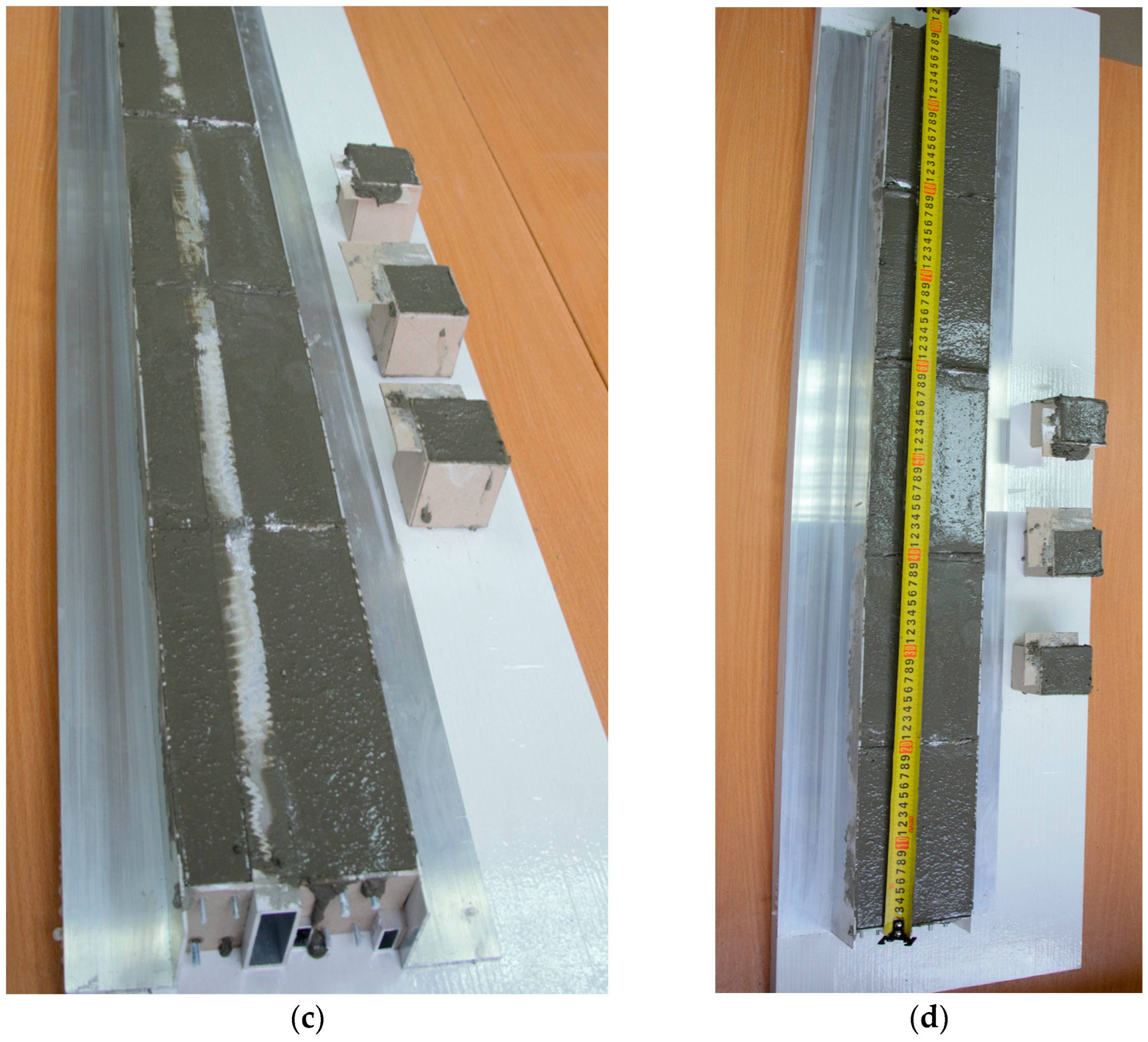
experiment using a series of small-scale models in the amount of five pieces for each type of model;
-
analytical calculation in accordance with regulatory documentation.
Modeling was carried out according to the instructions of the regulatory and technical literature [17,18,19,20]. According to the instructions of the design codes, the characteristics of the materials were assigned and controlled.
When performing the simulation, the following simplifications were taken into account:
  • construction material has no voids and its properties are the same in all directions;
  • stresses and relative deformations are interconnected by a linear relationship;
  • cross sections of elements remain plane after deformation;
  • the value of structural deformations is much less than their dimensions [21,22,23].
The calculation was carried out on the basis of SR 63.13330.2018 [7] analytically and in the Lira-Soft software package. For the most qualitative analysis of the bar structures’ operation features, their numerical simulation was performed using the apparatus of the finite element method. The model is set in a spatial formulation. The work of the material elements is physically and geometrically linear. Since the displacements of design schemes are negligible compared to the linear dimensions of structures, we did not take into account geometric nonlinearity which is a disproportionate relationship between deformations and displacements.
Two options for the cross-section of the elements (see Figure 2) and two options for applying loads on the bars are considered. As previously described, the cross sections are simplified to rectangular and tee shapes. The concrete class is taken equal to B25. To perform the experiment, small-scale models are taken with a scaling factor equal to 1:10.
When performing analytical calculations of the work of a section on the action of internal shear forces, the method of sections is used. The considered rod is calculated in an arbitrary section, the action which is represented by the following forces:
  • Longitudinal force N;
  • Shear force Q;
  • Bending moment M.
External forces are in balance with internal forces. Therefore, the whole system is in a state of static equilibrium.
According to [22], the calculation of the rods for the transverse load is performed according to the equation:
Q < Qb + Qsw
where Q is the total shear force in the support section, arising from all external forces located on one side of the cross-section. By sequential enumeration, we find the most dangerous load value within the area from h0 to 2h0; Qb is the shear force that the concrete can carry; Qsw is the shear force that is perceived by the transverse reinforcement bars.
By calculation, the most dangerous section is determined, in which the ratio Q/(Qb + Qsw) is maximum. As shown in Figure 3, the length of the studied section is taken to be at least 1.0h0 and not more than 2.0h0, where h0 is the working height of the bar element [24].
The hinged supports of the ends were set as the boundary conditions. Loads were represented by uniformly distributed forces.
However, for the purity of the experiment, the purpose of which is to clarify the effect of the concrete section on the perception of the shear force, it was decided not to use transverse reinforcement. Thus, Qsw is equal to zero. Longitudinal reinforcement is applied to perceive the bending moment. The destruction of short bars should occur along inclined sections from the action of shear force.
The force perceived by concrete section Qb is:
Q b = φ b 2 · R bt · b · h 0 2 C
where φb2 is adopted equal to 1.5 according to Russian standards, Rbt is the design tensile strength of concrete.
Determining Qsw is not a problem, since it is sufficient to know the cross-sectional area of the transverse reinforcement and the design strength. Of greatest interest is the shear force Qb. It is necessary to clarify how the configuration of the cross-section affects the shear force perceived by it. According to SR 63.13330 [7], the rigidity of the flanges is not taken into account in the T-section.
That is, the design codes consider the calculated section as one rectangle equal to 300 × 500 mm. From the point of view of the Russian standard, the sections shown in Figure 2 are equivalent to each other [25].
The numerical experiment made it possible to refine the distribution of internal force factors. The calculation scheme consists of three parallel spatial rods, which were modeled by one-dimensional bar finite elements (Figure 4). To ensure joint work, a kinematic association of displacements was performed. The load application scheme is indicated in two versions. The first type of load is a uniformly distributed load of 0.5 kN/m applied to the shelves. The second type of load is the application of 1 kN/m to the central rod.
The eccentricity of the center of gravity of the shelves relative to the central rod is presented in the form of an absolutely rigid kinematic insert.
Figure 5 shows the described structural diagram. Figure 6 shows a structural diagram, taking into account the assigned sections. As a result of this numerical simulation, the task was to obtain the distribution of internal forces between the central rib and flanges.
In addition to the numerical experiment, a small-scale experiment was carried out. For this, models of beams with sections were made, the diagrams of which are shown in Figure 7. The length of the beams was 200 mm. The concrete class was B25. In the manufacturing of concrete, a ready-made mixture of BASF master mako with hyper plasticizers based on polycarboxylates was used. Coarse inert filler had a size of no more than 2 mm. The ratio of the dry mixture to water by weight was 30 to 4. Reinforcement on the bottom face was presented by two rods with a diameter of 4 mm. Reinforcement on the upper face was presented by two rods with a diameter of 2 mm. Transverse reinforcement was absent. Laminated plywood and aluminum profiles of the required section were used as formwork, as shown in Figure 8. Teflon aerosol was used as a lubricant to minimize adhesion forces.
The use of these technologies made it quite easy to strip the formwork without damaging the reinforced concrete parts.
To control the strength of the concrete of the tested structure, three cubes with an edge size of 100 mm were molded and subsequently tested by the method of destructive strength testing on a press.
As a result, five small-scale T-beams and rectangular beams were obtained. To transfer the load from the press, a steel bar of rectangular Section 20 × 10 mm was used. The tested reinforced concrete beams are supported by similar steel bars. The complete set, ready for testing, is shown in Figure 9. The side surface of the beams is marked. The markings indicate the serial number and type of section: T is Taurus and P is rectangle.

3. Results

Uncertainty in design codes leads to the lack of a clear description of which shelf sizes (item 2 in Figure 10) should be taken into account, and which should not. The dimensions of the shelves can be significant and proportionate to the main rib of the section. Taking into account their rigidity will clarify the shear force that the section of concrete perceives.
With a section of 300 × 500 mm, a protective layer of concrete of 50 mm, and a concrete class of B25, Qb according to equation 2, is equal to:
Q b = φ b 2 · R bt · b · h 0 2 C = 1.5 · 1050 · 0.30 · 0.45 2 0.45 = 213   kN
The hypothesis put forward in this study is as follows:
The share of the shear force perceived by the shelves in the cross-section is proportional to the ratio of the moments of inertia of the main rib to the moments of inertia of the shelves.
The ratio of the shear force that the concrete of the tee section perceives to the rectangular one is equal to the ratio of the main central moments of inertia. To test this hypothesis, we perform the calculation by numerical methods.
The distribution of internal shear forces depending on the design scheme obtained as the result of the calculation is summarized in Table 2 and shown in Figure 11. The difference in the character of the shear force diagrams depending on the place of application of the load is visible. When a load is applied to the shelves, the force in the central rib is stepped. When a load is applied to the rib, the diagram of the shear force in the side flanges becomes stepped. The shear force diagram on the rib is linearly uniformly variable. The observed effect was formed due to the introduction of rigid inserts.
Confirmation of the most accurate result was obtained through a small-scale experiment. This experiment took into account the scale factor. The size of the coarse aggregate of the mixture is 2 mm, which is 10 times less than the coarse aggregate for conventional structures. However, the determining factor is the stress, which remains unchanged, since it is obtained by reducing the force to the area.
The reliability of the results obtained in the course of small-scale experiments is achieved due to the minimum required number of samples [26].
According to the results, it can be seen that the ratio of the moments of inertia and the perceived shear forces is equal when loaded on the main rib. The ratio of forces is 85% to 15% and 86% to 14%.
Before testing, the samples were marked with Ri and Ti, which means rectangular and tee sections, respectively. The tests were carried out in the laboratory LLC “Donskaya Stroitelnaya Laboratoriya” using Matest equipment (Figure 12), which allows for the fine adjustment of the load increase.
According to Equation (2) [19,20], beam models should have the following bearing capacity (support reaction):
Q b = φ b 2 · R bt · b · h 0 2 C = 1.5 · 0.105 · 3 · 4.5 2 4.5 = 2.13   kN
The total vertical load on the beam should not exceed 4.26 kN.
As a result of testing, one of the samples of the rectangular section, marked as 1R, was destroyed along the normal section in the middle of the span due to the fact that a mistake was made—the sample was turned over 180 degrees and the working longitudinal reinforcement, which is required at the bottom face, turned out to be at the top, as seen in Figure 13. The results for sample 1R were not taken into account in further studies.
This fact suggests that the working reinforcement along the bottom face is optimally selected. With even a slight decrease in its area, destruction occurs not along an inclined section in the support zone, but along a normal one in the middle of the span. Experimental results are summarized in Table 3.

4. Discussion

The article is a scientific study aimed at obtaining new knowledge on the development of existing ideas about the operation of bar structures and, at the same time, has practical significance. This allows us to simplify a number of tasks of the building complex, as the end user of our scientific research.
Researchers have conducted similar tasks in papers [27]. However, in their studies, they looked for somewhat different patterns. They assumed a rectangular cross-section of the rod element and varied the boundary conditions with the ratio of the bending moment and the transverse force.
Additionally, an interesting study led to [28] studies being canceled. The authors of this study perceive the shear load on a full-scale cantilever and continuous beams with a span of up to 7 m. The section taken was only rectangular. The influence of the destruction of the longitudinal working reinforcement and the deformation of concrete on the bearing capacity was studied in detail.
There are also studies of the operation of beams without transverse reinforcement, performed by numerical methods. For example, the authors of paper [29] used 3D finite elements to simulate the operation of these beams. The reinforcement was modeled with bar elements. In this case, patterns of cracking and reaching the limit state were obtained.
The above studies did not investigate the effect of the cross-sectional shape on the bearing capacity from the shear load.
It can be seen that the shear force is distributed between the longitudinal elements in a ratio that correlates with the ratio of their axial moments of inertia. It can also be seen that the change in the distribution of forces depends on the type of loading (on the edge or on the shelves). Our results agree with the works [18,30].
Small-scale experiments have proved the need to take into account the work of the shelves when the shear force is perceived by a complex composite section. The distribution took place in the ratio of 83% on the edge, and 17% on the shelves. These values show the convergence with the results of numerical simulation, in which the distribution was as follows: 86% on the edge, and 14% on the shelves. The discrepancy between numerical simulation and small-scale experiments is 3%.
Thus, when calculating screw-reinforced concrete piles, it is necessary to take into account the total section of concrete, taking into account the thread section falling into the section plane. This fact allows more efficient use of resource-intensive elements such as concrete in building structures. Additionally, for piles, it is necessary to take into account the reactive thrust of the surrounding soil, since part of the transverse load will be perceived by it. Numerically, this effect can be taken into account by the elastic bed coefficient distributed along the length of the pile shaft. For this study, the most simplified model was used.
The result obtained showed the correctness of the approach, which takes into account the shelves in the calculation of the shear force. It should be clarified to what extent the transverse reinforcement of the shelves complements the transverse reinforcement of the central rib. This question is relevant in view of the fact that the calculated length from Cmin to Cmax (see Figure 3) at the rib and shelves have different values.
It is also worth noting the characteristic pattern of cracking for the tee section. On the side surface of the shelves, the crack propagates at a certain angle to the horizontal axis. When moving to a vertical edge, the crack propagation angle decreases. This effect can be explained by two factors:
  • Influence of longitudinal reinforcement bars;
  • The critical fracture plane for the rib is farther away from the support than at the flanges. When the influence of shelves on cracking disappears, cracks try to make up for the untrodden path.
This effect indicates a complex distribution of shear stresses in the body of the structure.

5. Conclusions

As a result of the study, we obtained a number of scientific and practical results:
(1)
The results of the study obtained by various methods are in excellent agreement with each other. The influence of the ratio of the geometric characteristics of complex composite cross-sections on the distribution of internal forces is shown.
(2)
The bars simulating the T-section flanges took 14% of the transverse shear force.
(3)
A series of small-scale experiments were carried out, confirming the results of analytical and numerical calculations. Field experiments have proven the impact of the work of all elements of the section on the perception of shear force. The distribution took place in the ratio of 83% on the edge, and 17% on the shelves.
(4)
A recommendation is given to take into account the calculations, the total section, and not only the main rib, as indicated in [7].
(5)
It is established that the distribution of shear forces is proportional to the ratio of the axial moments of individual parts of the cross-section.
(6)
The experiments were carried out on small-scale models. In the future, it is planned to test elements of real sizes.
(7)
It is planned to conduct tests in interaction with the soil surrounding the pile.
Data processing results are given, and their parameters are both new material and the basis for further research.

Author Contributions

Conceptualization, A.C. and V.A.; methodology, A.P., E.R. and A.A.; software, A.C. and V.A.; validation, A.A. and E.R.; formal analysis, A.P. and A.A.; investigation, A.C., V.A., E.R. and A.A.; resources, A.C. and V.A.; data curation, A.C. and A.A.; writing—original draft preparation, A.C. and V.A.; writing—review and editing, A.P. and V.A.; visualization, A.A. and E.R.; supervision, A.C. and V.A.; project administration, A.C. and V.A.; funding acquisition, A.C., A.A., V.A., A.P. and E.R. All authors have read and agreed to the published version of the manuscript.

Funding

The APC was funded by Don State Technical University.

Institutional Review Board Statement

Not applicable.

Informed Consent Statement

Not applicable.

Data Availability Statement

The study did not report any data.

Acknowledgments

The authors would like to acknowledge the administration of Don State Technical University for their resources and financial support.

Conflicts of Interest

The authors declare no conflict of interest. The funders had no role in the design of the study; in the collection, analyses, or interpretation of data; in the writing of the manuscript, or in the decision to publish the results.

References

  1. Babalola, O.E.; Awoyera, P.O.; Le, D.H.; Romero, L.B. A review of residual strength properties of normal and high strength concrete exposed to elevated temperatures: Impact of materials modification on behaviour of concrete composite. Constr. Build. Mater. 2021, 123448, 296. [Google Scholar] [CrossRef]
  2. Song, W.; Wang, Q.; Qu, L.; Li, X.; Xu, S. Study of water absorption and corrosion resistance of the mortar with waste marble powder. Constr. Build. Mater. 2022, 128235, 345. [Google Scholar] [CrossRef]
  3. Scozzese, F.; Gioiella, L.; Dall’Asta, A.; Ragni, L.; Tubaldi, E. Influence of viscous dampers ultimate capacity on the seismic reliability of building structures. Struct. Saf. 2021, 102096, 91. [Google Scholar] [CrossRef]
  4. Dinh, N. Development and Application of a Data-Driven Methodology for Validation of Risk-Informed Safety Margin Characterization Models 2021; No. IRP-16-10918; North Carolina State University: Raleigh, NC, USA.
  5. Hou, X.; Chen, J.; Yang, B.; Wang, J.; Dong, T.; Rui, P.; Mei, Q. Monitoring and simulation of the thermal behavior of cast-in-place pile group foundations in permafrost regions. Cold Reg. Sci. Technol. 2022, 196, 103486. [Google Scholar] [CrossRef]
  6. Shi, Q.; Ma, L.; Wang, Q.; Wang, B.; Yang, K. Seismic performance of square concrete columns reinforced with grade 600 MPa longitudinal and transverse reinforcement steel under high axial load. Structures 2021, 32, 1955–1970. [Google Scholar] [CrossRef]
  7. SR 63.13330.2018 Concrete and Reinforced Concrete Structures. General Provisions. Available online: https://docs.cntd.ru/document/554403082 (accessed on 16 May 2022).
  8. Liu, Y.; Wei, Z.; Sui, B.; Wan, J.; Jiao, J. Finite element analysis of concrete circular pole substation structures under coupling action of carbonization-corrosion-load. In Proceedings of the Frontiers of Civil Engineering and Disaster Prevention and Control, Wuhan, China, 25–27 March 2022; CRC Press: Boca Raton, FL, USA, 2022; p. 145. [Google Scholar]
  9. Perumalla, M.; Yogeendra, R.H.; Laskar, A. Shear Tests on Post-Tensioned High-Strength Self-Consolidating Concrete I-Beams under Distributed Loads. ACI Struct. J. 2022, 119, 3–14. [Google Scholar]
  10. Al-Atroush, M.E.; Hefny, A.M.; Sorour, T.M. A Parametric Numerical Study for Diagnosing the Failure of Large Diameter Bored Piles Using Supervised Machine Learning Approach. Processes 2021, 9, 1411. [Google Scholar] [CrossRef]
  11. Prokopov, A.; Dolzhikov, P.; Akopyan, V. Foundation Deformations Modeling in Underworking and Hydroactivated Rocks. Adv. Intell. Syst. Comput. EMMFT 2017, 692, 647. [Google Scholar]
  12. Karpenko, N.I.; Kolchunov, V.I.; Travush, V.I. Calculation model of a complex stress reinforced concrete element of a boxed section during torsion with bending. Russ. J. Build. Constr. Archit. 2021, 3, 7–26. [Google Scholar] [CrossRef]
  13. Dolzhikov, P.; Prokopov, A.; Prokopova, M.; Hamidullina, N. Investigations of the regularity of the formation of a dip over the mine. MATEC Web Conf. 2018, 196, 03008. [Google Scholar] [CrossRef]
  14. Kruglikov, A.; Vasilchenko, A.; Kasprzhitskii, A.; Lazorenko, G. Atomic-level understanding of interface interactions in a halloysite nanotubes-PLA nanocomposite. RSC Adv. 2019, 67, 39505–39514. [Google Scholar] [CrossRef] [Green Version]
  15. Prokopov, A.; Zhur, V.; Medvedev, A. Application of the cartographic method of research for the detection of the dangerous zones of mining industrial territories. MATEC Web Conf. 2018, 196, 03009. [Google Scholar] [CrossRef]
  16. Pleshko, M.; Revyakin, A.; Malishevskaya, N. Investigation of the influence of the railroad track on the stress state of the tunnel lining. MATEC Web Conf. 2018, 239, 01020. [Google Scholar] [CrossRef] [Green Version]
  17. Meskhi, B.C.; Pleshko, M.S.; Voinov, I.V.; Caixao, J.J.Z. Safe operation of transportation tunnels based on predictive modeling of active geomechanical processes. Min. Inf. Anal. Bull. 2020, 8, 86–96. [Google Scholar] [CrossRef]
  18. Shapovalov, V.L.; Morozov, A.V.; Vasilchenko, A.A.; Okost, M.V.; Yavna, V.A. GPR calibration for determining the electrophysical properties of soil structural layers. Eng. Min. Geophys. 2020, 2020, 1–10. [Google Scholar]
  19. GOST 10180 Concretes. Methods for Strength Determination Using Reference Specimens. Available online: https://docs.cntd.ru/document/1200100908 (accessed on 13 December 2021).
  20. GOST 18105 Concretes. Rules for Control and Assessment of Strength. Available online: https://docs.cntd.ru/document/1200164028 (accessed on 14 December 2021).
  21. Yashchuk, M. Reinforced Concrete Elements Strengthened by Pre-stressed Fibre-reinforced Polymer (FRP)]/Maxim Yashchuk and Dmitry Smerdov. Transp. Res. Procedia 2021, 54, 157–165. [Google Scholar] [CrossRef]
  22. Prokopov, A.; Prokopova, M.; Stel’Makh, S.; Chernil’Nik, A. Plugging slurry (backfill) and surface cavity closure technology. E3S Web Conf. 2020, 157, 01014. [Google Scholar] [CrossRef] [Green Version]
  23. Mukutadze, M.A.; Mukutadze, A.M.; Vasilenko, V.V. Simulation model of thrust bearing with a free-melting and porous coating of guide and slide surfaces. IOP Conf. Ser. Mater. Sci. Eng. 2019, 560, 012031. [Google Scholar] [CrossRef] [Green Version]
  24. Prokopov, A.Y.; Sychev, I.V.; Revyakin, A.A.; Soboleva, O.N. Experimental studies of the reinforcement percentage effect on the modulus of soil deformation fixed by cementation. IOP Conf. Ser. Mater. Sci. Eng. 2020, 913, 022065. [Google Scholar] [CrossRef]
  25. Solop, S.; Kolobov, I. The design model of the electrical conductivity of a poroelastic thrust bearing. Mater. Sci. Eng. 2019, 560, 012033. [Google Scholar]
  26. Mahmood, W.; Mohammed, A.S.; Sihag, P.; Asteris, P.G.; Ahmed, H. Interpreting the experimental results of compressive strength of hand-mixed cement-grouted sands using various mathematical approaches. Arch. Civ. Mech. Eng. 2022, 22, 1–25. [Google Scholar] [CrossRef]
  27. Betschoga, C.; Tung, N.D.; Tue, N.V. Investigations on the influence of boundary and loading conditions on the shear resistance of FRP concrete beams without shear reinforcement. Compos. Struct. 2021, 262, 113335. [Google Scholar] [CrossRef]
  28. López, A.M.; Sosa, P.F.M.; Senach, J.L.B.; Prada, M.Á.F. Experimental study of shear strength in continuous reinforced concrete beams with and without shear reinforcement. Eng. Struct. 2020, 220, 110967. [Google Scholar] [CrossRef]
  29. Markou, G.; Al Hamaydeh, M. 3D finite element modeling of GFRP-reinforced concrete deep beams without shear reinforcement. Int. J. Comput. Methods 2018, 15, 1850001. [Google Scholar] [CrossRef]
  30. Mukutadze, M.A.; Opatskikh, A.N.; Morozova, A.V.; Zadorozhnaya, N.S. Mathematical model of wedge-shaped sliding support with low melting metal coated guide for partially filled working gap. IOP Conf. Ser. Mater. Sci. Eng. 2020, 941, 012064. [Google Scholar] [CrossRef]
Figure 1. Schematic representation of a helical reinforced concrete pile: (a)—side view of the pile segment, (b)—cross-section of the helical reinforced concrete pile, where: 1—pile shaft; 2—thread; 3—central axes; 4—thread trace in the section plane.
Applsci 13 02673 g001
Figure 2. Studied sections of rod elements: (a)—approximation of the section of a screw pile by replacing curvilinear sections with an equivalent composite tee, (b)—section that perceives shear according to Russian standards, where: 1—pile shaft; 2—equivalent tee section; 3—thread trace in the section plane; 4—rectangular section, equivalent to a tee. Dimensions are in mm.
Applsci 13 02673 g002
Figure 3. Limits of application of the design scheme, where: Qb is the force perceived by concrete, Qsw is the force perceived by transverse reinforcement, h0 is the working height of the cross-section, C is the distance from the support to the upper edge of the studied inclined section.
Applsci 13 02673 g003
Figure 4. Schematic representation of a bar finite element, where: l is the length of the element, φ is the angle of rotation of the element, X, Y, Z are the axes of global coordinates; X1, Y1, Z1 are the axes of local coordinates.
Applsci 13 02673 g004
Figure 5. Calculation scheme in the software package Lira-Soft 10.12. Three bar elements are presented: a central rib and two side shelves. The shelves are set with a vertical offset due to rigid kinematic inserts. Two options for applying loads are given: on the shelves at 0.5 kN/m and on the central rib 1 kN/m.
Applsci 13 02673 g005
Figure 6. Visualization of design schemes, taking into account the assigned cross sections. The central rib is blue. Two side shelves are beige. As can be seen from the visualization, the sections do not intersect. The lower faces of the rib and flanges coincide.
Applsci 13 02673 g006
Figure 7. The studied cross sections of the bar elements. Dimensions are given in mm.
Applsci 13 02673 g007
Figure 8. Formwork and reinforcement work and concreting of beams: (a)—formwork coating with Teflon grease, (b)—location of reinforcement in beams, (c)—concreting of beams and cubes, (d)—dimensions of the test samples.
Applsci 13 02673 g008aApplsci 13 02673 g008b
Figure 9. Test samples before the experiment. Whitish traces of Teflon grease are visible. Reinforcement protrusions are made to prevent errors: rods of larger diameter are laid at the lower faces. Support and cargo steel plates are located in the center of the photo between the beams.
Applsci 13 02673 g009
Figure 10. Sectional areas taken into account: 1—section considered in the calculation, according to [7], 2—section ignored in the calculation. It is necessary to find out how position 2 affects the operation of the section.
Applsci 13 02673 g010
Figure 11. Shear force diagrams in the vertical rib and flanges. It can be seen that the side shelves perceive part of the shear force. The stepwise or linear character of the change in the transverse force, as well as its value, depends on the place of application of the load.
Applsci 13 02673 g011
Figure 12. Sample testing process in the laboratory LLC “Donskaya Stroitelnaya Laboratoriya” with characteristic patterns of sample destruction: (a)—Matest test press, (b)—sample 2R sample test, (c)—sample 2T test.
Applsci 13 02673 g012
Figure 13. Test specimens after testing (on the element marked 1R, destruction is visible in the normal section due to an error during testing: a small reinforcement with a diameter of 2 mm was found in the tension zone.
Applsci 13 02673 g013
Table 1. Characteristics of the materials used in the calculation.
Sample NumberCodeName of MaterialClass Specific Gravity, kN/m3Design Compressive Strength, kPaDesign Tensile Strength, kPaDeformation Modulus, MPaPoisson Ratio
1SR63Heavy concreteB252514,50010503·1040.2
2SR63Reinforcing steelA500C78.5435,000435,0002.0·1050.3
Table 2. Summary table of calculation results.
ElementAxial Moment of Inertia, cm4Share in the Total Moment of Inertia of the Entire SectionShear Force According to the Loading Scheme No. 1, kNShare of the Total Shear Force, for the Entire SectionShear Force According to the Loading Scheme No. 2Share of the Total Shear Force, for the Entire Section
1Rib312,5000.852.620.782.880.86
2Shelves56,2500.150.740.220.480.14
Table 3. Summary table of experimental results.
Type of ElementFracture Force, kNSupport Reaction at Failure, kNAverage Value of the Support Reaction at Failure, kNShare of the Total Transverse Force, for the Entire Section
1R1--3.4690.83
2R26.153.075
3R37.153.575
4R47.13.55
5R57.353.675
6T17.613.8054.0581.0
7T29.414.705
8T37.453.725
9T48.584.29
10T57.533.765
Disclaimer/Publisher’s Note: The statements, opinions and data contained in all publications are solely those of the individual author(s) and contributor(s) and not of MDPI and/or the editor(s). MDPI and/or the editor(s) disclaim responsibility for any injury to people or property resulting from any ideas, methods, instructions or products referred to in the content.

