Article

Study on Fracture Behavior of Directly Covered Thick Hard Roof Based on Bearing Capacity of Supports

1
School of Mining Engineering, Anhui University of Science and Technology, Huainan 232001, China
2
School of Mining and Coal, Inner Mongolia University of Science and Technology, Baotou 014010, China
*
Author to whom correspondence should be addressed.
Appl. Sci. 2023, 13(4), 2546; https://doi.org/10.3390/app13042546
Submission received: 31 January 2023 / Revised: 13 February 2023 / Accepted: 14 February 2023 / Published: 16 February 2023
(This article belongs to the Special Issue Mechanics, Damage Properties and Impacts of Coal Mining)

Abstract

:
Mine pressure at the working face is severe due to it being directly covered by a thick hard roof. To further investigate the technology of controlling the mine pressure of a thick hard roof, the upper working face of 13,121 in Gubei mine of Huainan mining area was used as the engineering background, and similar simulation experiments, mechanical analysis, numerical simulation, and engineering applications were used to obtain the structure of a pre-cracked cut roof cut falling body, as well as establishing the mechanical model of hydraulic brace support resistance and direct covering. The results of the numerical simulation combined with the 20 m step pre-cracked top cutting showed that the cantilever length of the roof plate in the mining area was shortened by 25.61%, the stress concentration was reduced by 31.74%, and the stress level of the hydraulic brace was reduced by 26.59–28.38%, destroying the integrity of the thick hard rock body. According to the field monitoring data analysis, the working face’s initial pressure step and periodic pressure step were reduced, and the average dynamic load coefficients of the initial pressure and periodic pressure were 1.43 and 1.33, respectively, with a small dispersion of the dynamic load coefficient of the bracket. The pressure at the working face is regulated, and the chosen support equipment, in conjunction with the roof cutting scheme, can meet the thick hard roof’s support needs.

1. Introduction

As a source of China’s energy and industrial raw materials, coal plays a crucial role in China’s energy security and economic development [1]. However, coal resources in China are widely distributed, the geological structure is complex, and safety problems often occur during mining. Roofing accidents are the most serious safety issue and they account for as much as 33% of coal mine accidents [2,3,4]. As a key factor in roofing accidents, thick hard roofs under a violent pressure have always been the focus of coal mine disaster prevention and control [5]. In the process of coal seam mining, the thick hard roof can easily form a large cantilever structure, which accumulates a lot of energy in the rock strata. The sudden breaking of the thick hard roof often causes a huge energy release and a strong dynamic load effect, which easily leads to support damage, face collapse, rock emergencies and other strong power disasters, which seriously threatens the safety of people and equipment in the face [6,7,8].
Jianjun Ma et al. [9,10,11] found that the larger the underground space, the worse its stability. By establishing a coupled thermo-elastic-plastic damage model of concrete under dynamic load, it is noted that this model can be upgraded to anisotropic damage response or large deformation in further research, which provides a mechanical calculation basis for studying the breaking performance of a thick and hard roof. To study the strong mineral pressure control technology for thick hard roofs in more details, Kaige Zheng et al. [12] developed multistage hydraulic fracturing technology for hard and thick roofs, and established a mathematical model of hydraulic fracturing locations, and a synergistic support system consisting of a collapse fill, coal column, and pressure-bearing layer. The results showed that hydraulic fracturing effectively reduced the periodic pressure step and stress level. Jianquan Tang et al. [13] proposed using pre-cracked blasting to control the thick hard top slab, and studied the effects of charge structure and charge amount on the prefracture blasting effect through underground blasting tests, and finally determined suitable prefracture blasting parameters. Chen Zhang et al. [14] simulated the deep hole blasting process of a thick hard top slab by using finite elements and discrete element methods. After blasting, the small-energy mining seismic signal within 20 m of the top slab suddenly increased and gradually shifted to the hollow area and the front of the workings. At the same time, the disruption of high-level rock layers released a large amount of strain energy, and the stress of the roof was obviously reduced. Baobao Chen et al. [15,16] established a mechanical model of periodic damage of a thick hard roof based on the roof load and rock block destabilization characteristics, and studied the relationship between the blast spacing, blast angle and bracket working resistance and the optimal parameters. Numerical simulation software was also used to analyze the crack evolution law and the transport pattern of the thick hard roof, and the best pre-cracking parameters were determined. Junce Xu and other scholars [17] studied the stability of rock formations in underground engineering, and further researched the stability of rocks under dynamic load by establishing a decay function model to analyze and explore the mechanical behavior of sandstone under static load. Chengxing Zhao et al. [18] investigated the sprouting and expansion of microcracks during the deformation and damage of rocks using a triaxial system as well as AE techniques, and the results showed that pressurization of rock microcracks facilitated the development and expansion of cracks, again verifying that hydraulic pressurization and pre-cracking blasting can effectively damage thick hard roofs.
Hydraulic brackets are a form of coal mining working face support equipment. The long cantilever structure formed by a thick hard roof during coal seam mining, which is difficult to collapse by itself, has put forward higher requirements on the working resistance of hydraulic brackets at the working face. Experts and scholars in the industry have never stopped exploring the relationship between the roof plate and the hydraulic support. Guofa Wang et al. [19,20] believe that a reasonable bracket initial bracing force and working resistance can not only keep the bracket with a certain stiffness and effectively control the sinking amount of the roof plate but can also reduce the damage of the roof plate to the bracket by actively relieving the pressure and maintaining the bracket and the surrounding rock system in a dynamic balance.
Xiexing Miao and Minggao Qian [21,22] established an overall mechanical model of quarry rock support, focusing on the coupling relationship between the bracket and surrounding rock and the stability of the basic top rigid block stability, and revealed the relationship between the bracket load and the average sinkage of the roof plate. On this basis, Yajun Xu et al. [23] studied the coupling relationship between the hydraulic bracket and surrounding quarry rock from the aspect of stiffness coupling. The coupling equation between the hydraulic bracket and the surrounding rock was established, and the hydraulic bracket support strength calculation formula was modified, which increased the qualitative analysis of the coupling relationship between the hydraulic bracket and surrounding quarry rock to the quantitative research level. Wang Dalong et al. [24] created a numerical simulation model of a four-legged hydraulic brace using ADAMS software, replacing the column with a variable stiffness spring for the simulation of the elastic properties of the column. The response characteristics of the hydraulic bracket column were obtained under different surrounding rock coupling states. Marcin Witek et al. [25] studied the stress distribution of hydraulic supports under different working conditions through finite element analysis and laboratory tests. The results show that the coupling form of surrounding rock has an influence on the stress distribution of the support, and better coupling conditions can reduce the stress concentration of the support.
The aforementioned research findings indicate, to some extent, that hydraulic pre-splitting or blasting pre-splitting has an obvious effect on the prevention of rock pressure in thick hard roof faces. The coupling relationship between the support and surrounding rock is also investigated, but there is a dearth of research on the stability of a thick hard roof that is directly covered by hydraulic support.

2. Motivation and Novelties

At present, the research on top cutting of a thick hard roof is mostly limited to proving that top cutting can effectively improve the stress environment of a stope, and the determination of a top cutting step is only based on field engineering experience, without further discussion.
The first mining face is directly covered by a thick hard roof, so due to the research’s content limitations, this paper combines the 13,121 upper working face as the specific condition. To explore the structure after the roof is cut, FLAC3D numerical simulation and physical similarity simulation are used extensively. The mechanical model between the hydraulic support and the shear falling body of the hard thick roof is established in accordance with the boundary conditions of the broken roof structure, and the relationship between the reasonable length of the shear falling body of the hard thick roof and the resistance of the hydraulic support is investigated.

3. Project Overview and Pressure Control Analysis of a Directly Covered Thick

Hard Roof

The upper working face of 13,121 in the Gubei Mine in the Huainan Mining Area is directly covered by an 11.6 m thick hard main roof because it is the initial mining face. A long cantilever construction frequently occurs as a directly covered thick hard roof. The thick, hard roof plate will instantaneously fall when the cantilever length reaches its limit length, releasing a significant quantity of energy. The main roof’s classification index can be represented by the basic initial weighting equivalent of the roof, and Table 1’s specific classification index is displayed. According to the method for calculating the initial pressure equivalent of the roof plate [26], the degree of incoming pressure when the overlying thick hard roof breaks can be quantitatively reflected:
P e = 241.3 ln ( L ) 15.5 N + 52.6 h m
where Pe is the main roof pressure equivalent; L is the initial pressure step of the thick hard main roof, m; N is the ratio of direct roof thickness and coal seam mining height; and hm is coal seam mining height, m; the coefficients in the formula are obtained based on a large number of field data.
In a previous study on the directly covered thick hard roof at the 13,121 upper working face, the initial breaking step was found to be 57.59 m [27], and the actual parameters of the working face were substituted into Equation (1) as a means of obtaining its incoming pressure equivalent of 1177.83 at the time of initial breaking. According to the main roof classification index table in Table 1, it can be judged that the mine pressure in the working face with a thick and hard roof is extremely severe, and it is easy to cause strong power disasters, such as hydraulic support pressing.
With the directly covered thick hard roof, the incoming pressure equivalent Pe is mainly related to L and hm, while mining height hm basically remains unchanged in the coal seam recovery process, which can be simplified as Equation (2) and analyzed from the relationship curve between Pe and L.
P e = 241.3 ln ( L ) + A
where A is an undetermined formula related to L and hm.
From Figure 1, the excessive breaking step of a thick hard roof leads to severe mine pressure, and shortening the step of the roof is the most direct and effective measure to improve the mine pressure. At the same time, the blasting method is more conducive to energy release and the development of elastic layer cracks. Deep-hole blasting technology has obvious effects on weakening the coal seam roof, preventing spalling and controlling the mine earthquake induced by high-energy mining [14]. Therefore, according to the engineering situation of the directly covered thick hard roof in Gubei Mine, advanced deep-hole blasting caving can be used to control the directly covered hard sandstone roof.
Through the analysis of influencing factors of mine pressure in a thick and hard roof stope, it is concluded that the mine pressure strength of a directly covered thick and hard roof working face depends on the breaking step of a thick and hard basic roof and the size of the stope. It is difficult for the thick, hard roof to immediately collapse under its own weight after the coal seam has been mined. Industry experts say that the length of the cantilever that the roof creates in the goaf and the size of the breaking step are both related to the thickness of the roof. The risk of ground pressure in the working face also increases noticeably due to the impact force produced by the movement of the thick, hard roof. A directly covered thick and hard roof leads to a large range of rock pressure in the working face, and a large impact load when unstable.

4. Analysis of Mining Instability of Roof Cut Falling Structure

4.1. Physical Form of Cut Falling Body of Directly Covered Thick Hard Roof

The upper working face of 13,121 in Gubei Mine is the first mining face, and the coal seam thickness of 7.3~8.3 m layered mining is adopted, and the mining height is controlled within 3.8 m during initial caving. The 13,121 upper working face adopts an inclined longwall layout, with a face length of 205 m and a coal seam dip angle of 3~14°, with an average of 8°. The false roof of the working face is missing, and it is directly covered by the fine sandstone of the main roof.
Based on the geological conditions on the 13,121 upper working face, physical similarity simulation experiments of pre-cracking cut roofs were conducted. The model used a 3.0 m by 0.3 m by 1.5 m model frame and primarily used sand as an aggregate, supplemented with lime and gypsum as the cementing material, referencing the physical and mechanical properties of rocks from the Gubei Mine for proportioning. The material was laid layer by layer in a two-dimensional plane strain experimental table, and steel plates were pre-placed in the thick hard top rock layer during the model laying as a means of simulating a pre-cracked cut roof. Figure 2 shows the physical similar experimental platform and the rock column chart.
Through the observation of the physical form of the directly covered thick hard roof during the experiment, it was found that after pre-cracking and cutting the roof, the thick hard roof cut-off body was supported by the coal seam near the coal wall end, and the support boundary was a simple support condition, and the support boundary was in a free condition when it slipped directly near the mining area side. The overall combination is a “Simple support—Free” structure, as Figure 3 demonstrates.

4.2. Analysis of the Bearing Capacity of the Roof Cut Falling Body—Hydraulic Support

In previous studies, the beam theory was often used to study the roof, but the beam theory could not reveal the spatial movement of the roof. Therefore, researchers began to pay attention to the application of slab theory in roof behavior [5,28]. Limited by field observation means and existing experimental techniques, it is impossible to obtain the roof structure after roof cutting through field observation. However, by combining a physical similarity experiment with a numerical simulation, as illustrated in Figure 4, it is possible to examine the crack development features following field pre-splitting blasting through a rock stratum peeper and acquire the roof structure. Pre-cracking roof structure should be examined.
Combined with the working conditions of the 13,121 upper working face as the first Mining Face, the roof model can be simplified as two opposite edges clamped, one side simple support, the other side free plate (hereinafter this boundary condition is referred to as CSCF). The CSCF roof model can be seen in Figure 5.
The mechanical roof plate model takes the middle of the working face as the coordinate origin, the direction of the working face arrangement as the x-axis, the direction of the coal wall towards the goaf as the y-axis, the long side of the model as 2a, the short side as b (2a > b), the thickness of the roof plate as h, the modulus of elasticity as E, Poisson’s ratio as μ, the deflection surface of the plate as ω, and the force that acts on the overlying rock layer of the roof plate of the working face as the uniform load q0.
The key layer discrimination method [26] is used for determining the overburden bearing key layer:
( q m ) 1 = E 1 h 1 3 i = 1 m ( γ i h i ) i = 1 m E i h i 3 ( q m ) 1 < q 1
where: (qm)1 is the load of the mth rock layer on the first rock layer and γi, is the volumetric weight, Ei, is the elastic modulus and hi is the thickness of the rock layer. From Equation (1) it can be determined that the directly covered thick hard roof is the critical layer, and the uniform load q0 on it is 0.765 MPa. The mechanical parameters of the rock formation are as follows: the thickness is 11.6 m, the bulk weight is 26.8 kN/m3, the modulus of elasticity is 29 GPa, the tensile strength is 7.21 MPa, and Poisson’s ratio is 0.31.
The boundary conditions of the CSCF plate are determined based on the model setting condition as:
{ ω | x = ± a = 0 , ω x | x = ± a = 0 , ω | y = 0 = 0 , 2 ω y 2 | y = 0 = 0 , ( 2 ω y 2 + μ 2 ω x 2 ) | y = b = 0 , [ 3 ω y 3 + ( 2 μ ) 3 ω y x 2 ] | y = b = 0
.
According to the boundary conditions, the following equation is selected for the deflection surface of the CSCF plate.
ω = C [ 1 + cos ( π x a ) ] sin 2 ( π y 2 b )
Based on the principle of minimum potential energy and the Ritz method [29], the total potential energy of the CSCF plate is determined from Equation (5) as:
E P = D 2 A ( 2 ω x 2 + 2 ω y 2 ) 2 d x d y ( 1 μ ) D A 2 ω x 2 2 ω y 2 ( 2 ω x y ) 2 d x d y A q 0 ω d x d y
where A is the integral boundary condition, x ∈ [−a, a], y ∈ [0, b]. Equation (6) is used to obtain:
E P = D C 2 π 4 ( 3 a 4 + 2 a 2 b 2 + 3 b 4 ) 16 a 3 b 3 C a b q 0
Deflection coefficient C is obtained thus:
C = 8 a 4 b 4 q 0 D π 4 ( 3 a 4 + 2 a 2 b 2 + 3 b 4 )
where D is the bending stiffness of the plate, N/m. This is calculated from the following equation:
D = E H 3 12 ( 1 μ 2 )
where E is the modulus of rock elasticity, GPa; and H is roof thickness, m. The CSCF plate deflection surface equation is then:
ω = 96 ( 1 μ 2 ) a 4 b 4 q 0 E H 3 π 4 ( 3 a 4 + 2 a 2 b 2 + 3 b 4 ) [ 1 + cos ( π x a ) ] sin 2 ( π y 2 b )
The hydraulic bracket acts as a form of working face support equipment, carrying the load of the overlying roof plate, and the overlying rock movement affects the working state and bearing characteristics of the bracket and roof after pre-cracking blasting; the roof plate bends and sinks under the action of multiple factors and acts directly on the hydraulic bracket. With the movement of the broken roof, combined with the deflection of the overlying roof and the change of the stiffness of the support, the support resistance can be obtained [30]. Considering the effective bracket support efficiency, the brace resistance can be expressed as:
F = K Δ ω / η
where F is hydraulic bracket support resistance, kN; K is bracket stiffness, N/m; Δω is the degree of overburden roof deflection change, m; and η is effective bracket support efficiency.
According to Equation (10), the roof deflection surface can be derived during the excavation of the working face.
The three-dimensional surface of roof deflection in Figure 6 shows that the deflection deformation of the clamped edge and simple support edge is small in the process of coal seam mining, and the maximum deflection area is concentrated in the middle of the free edge. According to the reflection of the top deflection surface, the maximum deflection position of the roof (x = 0) is in the middle of the working face, as modelling and analysis of the thick hard top cut fall and hydraulic support shows that pressure sinks.
In Figure 7, l is the hydraulic bracket control roof distance, m; b is the cut-off body length, m; and ωm is the degree of roof end movement, m. The relationship between hydraulic support resistance and roof cut falling body is then as follows:
F = K ω ( 0 , l ) / η = 192 ( 1 μ 2 ) a 4 b 4 K l q 0 sin 2 ( π l 2 b ) E η H 3 π 4 [ 3 a 4 + 2 a 2 b 2 + 3 b 4 ]
In the above equation, hydraulic support resistance F is related to working face length 2a, cut falling body length b, roof thickness h, and the lithological parameter E.
Figure 7. Main roof pressure sinking structure.
Applsci 13 02546 g007

4.3. Factor Analysis of Brace Bearing Performance

In the Gubei Mine 13,121 upper working face in the Huainan Mining area, the directly covered thick hard roof thickness is 8.4~15.4 m, with an average thickness of 11.6 m. The relevant parameters of the working face and the directly covered thick hard roof are 2a = 205 m; H = 11.6 m; E = 29 GPa; q0 = 0.765 MPa; l = 5 m; μ = 0.31; K = 1.65 × 10⁵ kN/m; and η = 0.9.
The effect each variable factor has on the influence of support resistance F was analyzed using the control variable method and the following conclusions were reached.
(1)
The relationship graphs between the aforementioned six indicators and F show that the stent resistance will increase with the length of the broken body following pre-cracking and top cutting.
(2)
Figure 8a–d show that when one of the other factors, such as roof load q0, face length 2a, bracket stiffness K, or the top control distance l, is changed, the result is an increase in support resistance F, proving that all of the other factors are positively correlated with bracket resistance.
(3)
The slope of each element in the four graphs (a–d) indicates how sensitive that factor is to the impact of hydraulic support resistance. Working face length is not the primary element that determines the increase in brace resistance for the directly covered thick hard roof working face because the brace resistance responds more visibly to changes in K, l, and q0 while the slope of the change in working face length is flatter.
(4)
In Figure 8e,f, the hydraulic support resistance at the working face is negatively correlated with the strength and thickness of the roof rock layer. The required working face bracing resistance will be smaller the stronger and thicker the roof plate is, indicating that the thick hard roof plate bears the overlying rock in addition to its own load on the coal seam within a range, reducing the load acting on the coal seam and the required bracing resistance.
Figure 8. Analysis of influencing factors of support resistance F: (a) Relationship curve of F and 2a; (b) Relationship curve of F and l; (c) Relationship curve of F and K; (d) Relationship curve of F and q0; (e) Relationship curve of F and E; and (f) Relationship curve of F and H.
Applsci 13 02546 g008
Hydraulic brace working resistance is affected by the directly covered thick hard roof. The above analysis demonstrates that bracket stiffness, top control distance, thick hard roof load, lithological strength of the roof and roof thickness affect the working resistance of the hydraulic bracket.
In combination with the working face support equipment support parameters and coal rock strength conditions, calculation software was used to invert Equation (12) to find the length of the cut falling body and the maximum length of the calculated cut falling body was 20.42 m.

5. Determination and Verification of the Structure Size of the Cutting Block

In pre-cracking blasting roof cutting of a thick hard roof, the height of roof cutting and roof cutting step pitch are important technical factors that affect the roof cutting effect, and the height of roof cutting should be greater than the thickness of the main roof. According to the collapsed rock fragmentation and expansion characteristics, the height of roof cutting satisfies the relationship [31]:
h k M k p 1
where hk is the depth of presplitting blasting hole, m; M is the thickness of coal seam in the upper working face of 13,121, m; kp is the coefficient of rock fragmentation and expansion, and the value of the fragmentation and expansion coefficient of hard rock is between 1.2 and 1.6.
For the thick hard roof, the fragmentation and expansion coefficients are not too large following the collapse of the cut roof. Considering the main roof lithology and the actual site situation, the calculated cut roof height is taken to be 16 m.
Combining the previous analysis and the lithological characteristics of the 13,121 upper working face, theoretical analysis was performed in relation to cutting the hard roof of the Gubei Mine. Considering the safety and economic benefits, deep hole blasting is used to pre-crack the roof, and the specific construction plan of the directly covered section of the thick hard roof is shown in Figure 9.
In order to verify the feasibility of the presplitting scheme, the effect of an uncut top and a 20 m step pitch cutting top is simulated by numerical simulation.
The numerical simulation model was constructed based on the actual geological conditions on the upper working face of coal 13,121 in the A group of the Gubei Mine, and the calculation range of the entire model was 300 × 146 m. An equivalent uniform load of 10.6 MPa was applied in the vertical direction for the rock layer not simulated on the top of the model. At the same time, to eliminate boundary influence, 50 m was left as boundary coal columns at both ends of the model. The bottom boundary and the left and right boundaries were constrained by displacement fixed conditions.
The main rock mechanics parameters that were studied in the model can be seen in Table 2:

5.1. Collapse Displacement Analysis

When the roof was not cut, the directly covered thick hard top roof exhibited good integrity, as can be seen in Figure 10a, and the first collapse of the thick hard top occurred at 80 m of excavation. At this time, the maximum sinking of the roof was 3.43 m, the compaction of the collapse of the roof plate in the goaf area lagged behind, and the distance from the full compaction position to the mining position of the working face was approximately 68.5 m.
Figure 11a shows how cutting the roof reduces the integrity of the thick hard roof. Pre-cracking the cut top speeds up the settlement process of the thick hard roof and reduces the cantilever distance of the roof. The initial collapse step was 60 m, and the top slab settled to a maximum of 3.69 m. The collapse compaction lag distance of the thick hard roof was decreased to roughly 41 m after the roof cutting treatment, thereby decreasing it by 40.15% and demonstrating that cutting the roof shortens the length of the top slab collapse body.

5.2. Stress Analysis

As is shown in Figure 12a–d, the thick hard roof was not treated, and the stress concentration peak in front of the coal wall was 29.4 MPa during the thick hard roof initial collapse. During the subsequent development of the overburden collapse, the stress peak was between 38.2~43.4 MPa, and the stress concentration degree was approximately equivalent to 3.60~4.09 times the original stress level of the rock. For a thick hard roof directly covering a working face, an overly high stress concentration will increase the risk of coal wall damage.
Figure 12e–h illustrates that, following roof cutting, the peak stress concentration in front of the coal wall was 20.2 MPa. After that, the stress concentration was reduced to 2.47–2.78 times the rock’s initial stress level, or a reduction of about 31.74%. The peak stress in front of the working face was 26.2~29.5 MPa. The stress propagation path was interrupted by a visible stress release area at the cut, which also lowered the apparent strength of the mine pressure in the working face.
A simulation of the brace force was also conducted and the statistical results of this can be seen in Figure 13. The observation and analysis found the bracket working resistance started increasing significantly with the advancement of the working face. The hydraulic bracket reached peak working resistance when the roof initially collapsed, and then the bracket working resistance exhibited dynamic “wave” changes as the working face continued advancing. When top cutting was not performed, bracket support force was between 17,115~18,953.4 kN, and the maximum value was 18,953.4 kN. After performing top cutting, bracket working resistance changed more smoothly during the coming pressure period than prior to the roof being cut, and the overall force level was smaller than it was before the roof was cut. After the roof was cut, and the overall bracket force level was 13,332.02~14,972.4 kN; the overall decrease was 26.59~28.38%.
The results of the numerical simulation analysis show that cutting the top in a 20 m step effectively reduces the high stress concentration brought on by the thick hard top slab, reduces the cantilevering degree of the roof plate in the goaf area, and significantly lowers the working resistance of the hydraulic bracket. In conclusion, under conditions of thick hard top slabs, the pre-cracked cutting roof can control mine pressure on the working face.

6. Analysis of the Bearing Performance of the Working Face Site Bracket

For the 13,121 upper working face in the Gubei Mine, some brackets were selected as monitoring points, and the “KJ216B Coal Mine Roof Dynamic Monitoring System” was used for monitoring the hydraulic brackets, including the incoming pressure step, the hydraulic bracket working resistance and the change of initial bracing force, and other working face pressure indicators.
Monitoring substations were set up in each ministry of the working face at intervals of eight hydraulic supports, totaling fifteen hydraulic supports. So as to better detect and analyze the pressure change of the top plate during the process of recovery, at the same time, the monitoring data of each substation was transferred to the ground computer for storage and analysis in time. The corresponding position of monitoring substations and brackets is shown in Table 3.
Statistics of the monitored data of each measuring point are shown in Table 4 and Figure 14, and we analyzed the data in the chart to reverse the real-time roof weighting situation.
From the above data, it can be seen that the initial pressure step of the working face was 31.1~33 m, with an average of 40.8 m (8.5 m for open-off cut). In the statistical process of 18 cycles of pressure, the entire working face cycle pressure step range was between 17.4~21.3 m, with an average of 19.6 m, thereby proving that the site pre-cracked top cutting had a better breaking effect.
Working resistance and dynamic load coefficient of hydraulic support, as two technical indexes of hydraulic support, can better reflect the mine pressure situation of the working face. The changes to working resistance and the dynamic load coefficient of hydraulic support are shown in Figure 15. After cutting the top, the working resistance of the hydraulic bracket in each part fluctuated when the basic top came to pressure for the first time, the working resistance of the hydraulic bracket ranging from 25 to 41.6 MPa. The average working resistance of the hydraulic bracket before the first time to pressure was 26.2 MPa, and the average working resistance in regard to pressure was 36.8 MPa. There were some differences with the dynamic load coefficient of each part for the first time to pressure, and the distribution range was 1.09 to 1.67, and the average dynamic load coefficient was 1.43. The working resistance of the hydraulic bracket during the period of coming to pressure ranged from 24.12 and 37.74 MPa, and the average dynamic load factor was 1.33.
In the process of coal seam mining, the working resistance of each support increases, and the statistics of the working resistance frequency of the support are shown in Figure 16. After roof weighting, the working frequency of the support resistance is below 30 MPa, and the frequency of the resistance is between 30 MPa and 40 MPa, which is 9.6%. The opening value of the hydraulic valve of the support is 41 MPa, accounting for only 0.9%. The field performance is that the pressure relief is only generated locally when the support is weighted, which is not seen.
In conjunction with the force analysis of the previous bracket, it can be seen that the braced cover type ZZ13000/24/50 bracket chosen for the 13,121 upper working face fully satisfies and can be tailored to the requirements for safe production after pre-cracking and cutting the top of the 11.6 m directly covered hard slab with a 20 m step.

7. Discussion

Because of its high strength, the thick hard top plate is not easy to break and collapse independently in the coal production process, resulting in long breaking steps and a long cantilever structure. A long cantilever structure often causes hydraulic brackets to be overwhelmed, rock explosions, coal wall flake gangs and other violent dynamic load phenomenon. It does not satisfy the working face’s safety production criteria. Following a thorough analysis of the thick hard roof of the quarry, it is common practice to use pre-cracking blasting, roof cutting, hydraulic fracturing, and other technical means to weaken the thick hard roof’s rock layer, to shorten the pressure step of the roof, and to shorten the roof cantilever in order to control mine pressure on the working face.
The working face’s hydraulic bracket can most accurately reflect the law of mine pressure. On the basis of regulating mine pressure, acceptable measures and a roof cutting scheme can better maintain the bracket at the working face in a stable functioning condition for directly covered thick hard roofs. Additionally, based on the working face support capability, it offers recommendations for the pre-cracking program for thick hard roofs. In order to determine the appropriate top cutting step for the bracket in reverse, this paper conducted research on the top cutting scheme of directly covered thick hard roofs in accordance with the working face bracket situation. It also provided theoretical and technical support for related engineering situations by establishing the mechanical relationship between the hydraulic bracket and roof cutting fall.
In contrast to earlier research findings on the effectiveness of roof cutting in reducing the stress environment of the stope, most current research is mainly focused on roadway roofs, seeking to compromise the integrity of roof overburden. In contrast to the pre-splitting scheme in this research, which is parallel to the working face, the determination of the roof cutting step is carried out theoretically according to support selection. This provides the calculation basis for the selection of a roof cutting step in the directly covered working face with a thick and hard roof. The determination of a roof cutting step is frequently selected according to empirical equations.

8. Conclusions

(1)
The directly covered thick hard roof fracture step is too long, which is the main cause of the work surface seeming to have intense ore pressure, according to analysis of the equation of incoming pressure equivalent of the roof plate. For the working face of a thick hard roof plate, using technical means to shorten the pressure step is an effective method for controlling mine pressure at the mining site.
(2)
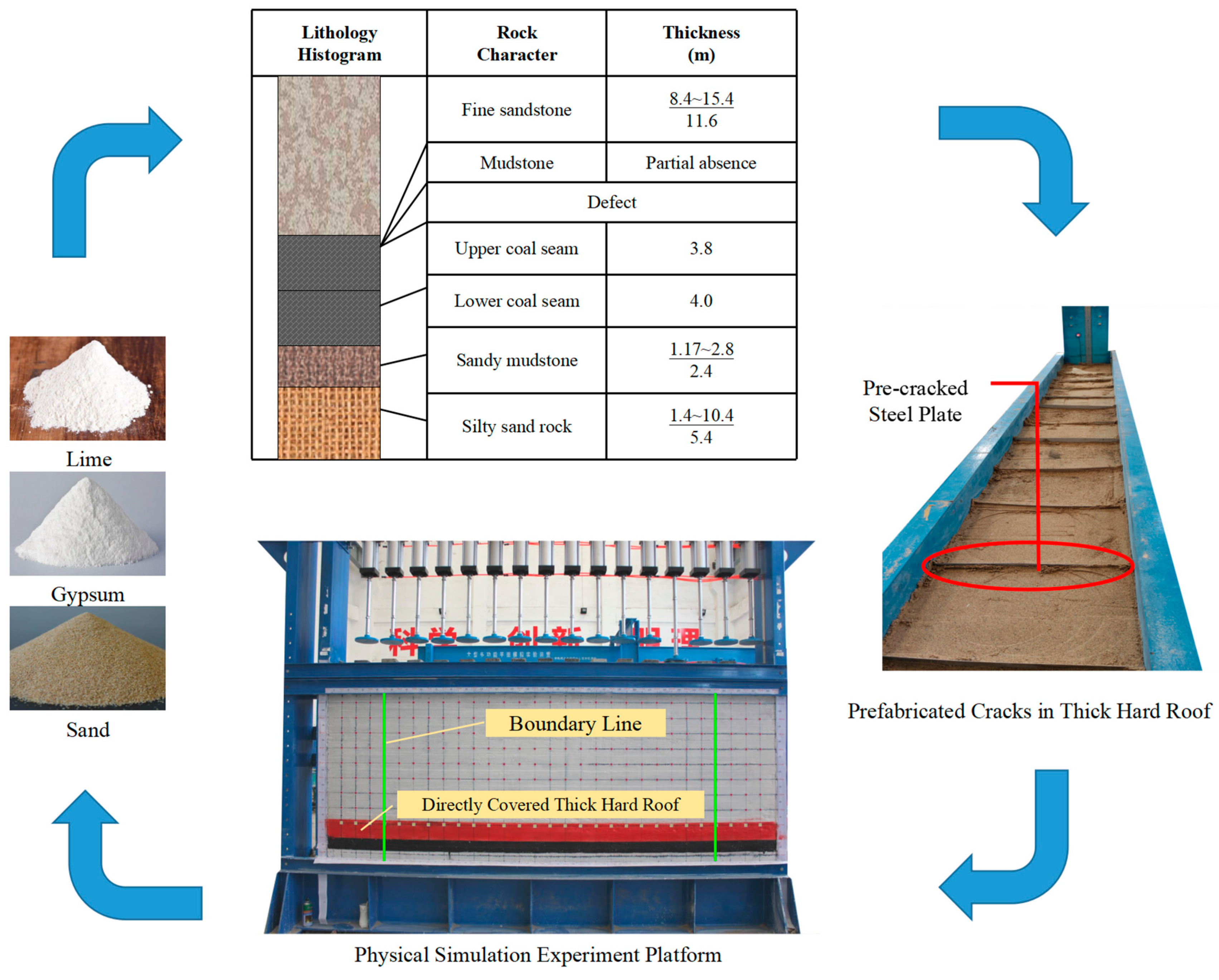
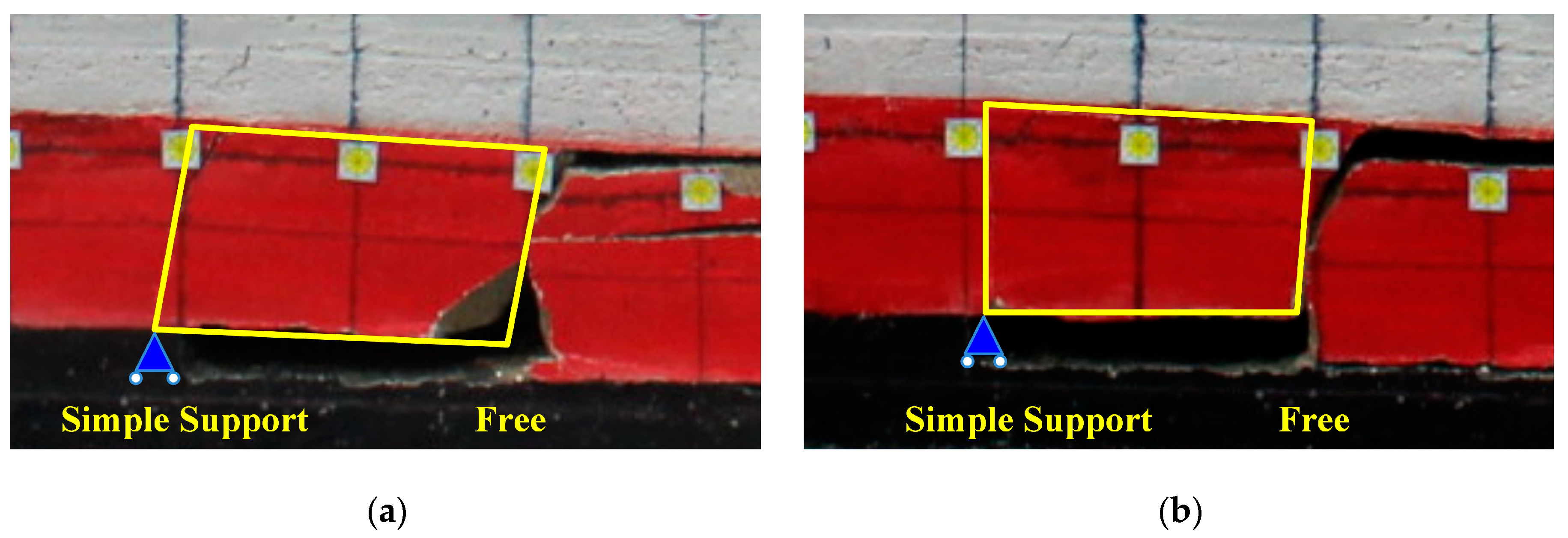
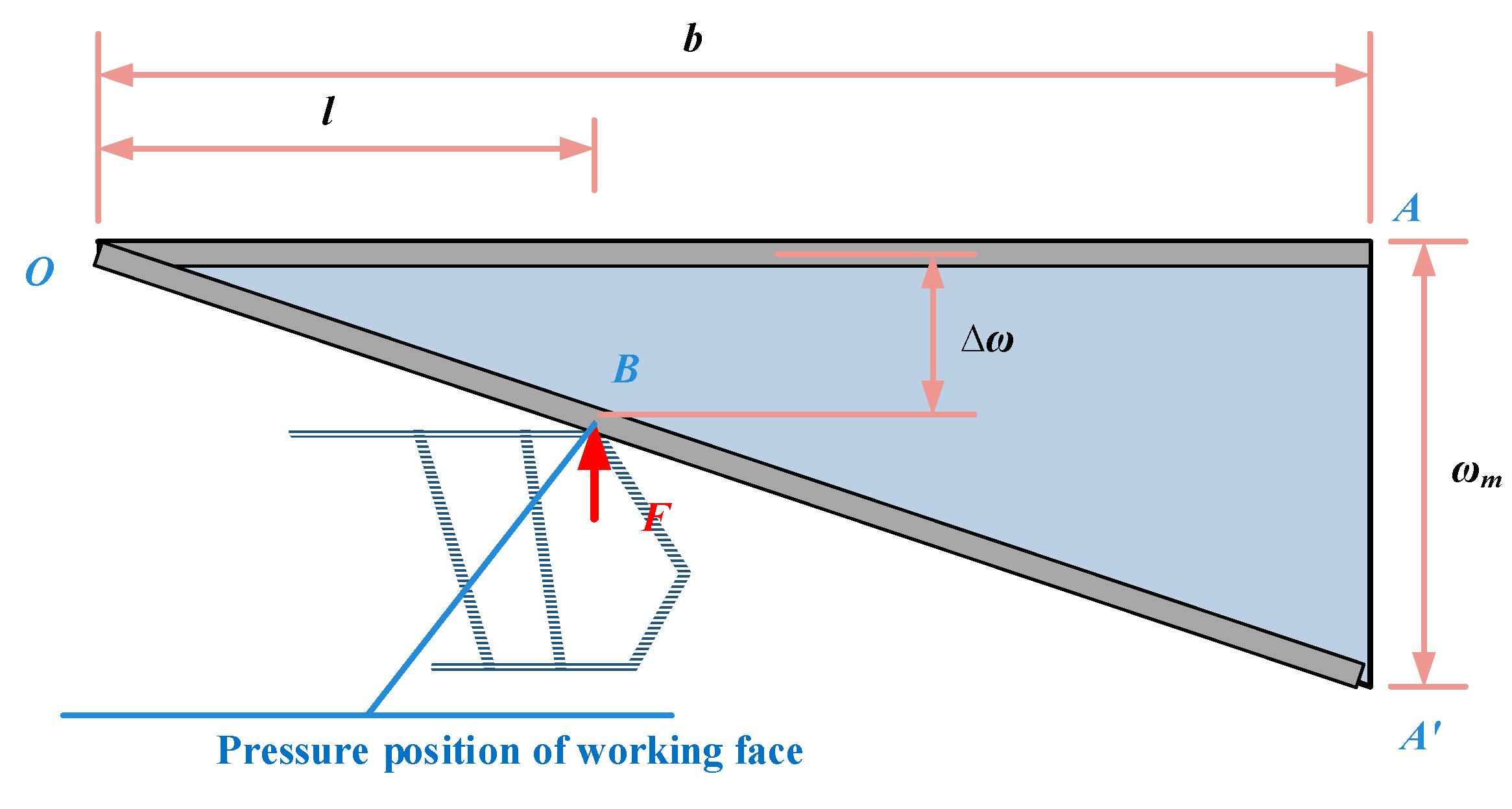
The pre-cracked cut top effectively reduces cantilever length, and the cut fall body is a “simple supported—free” structure, according to modeling investigations using physically similar materials.
(3)
A mechanical model of a thick hard roof cut falling body is developed using the plate structure theory, and mechanical analysis is carried out based on how the bracket and roof interact. It was discovered that the hydraulic bracket resistance F of the working face has a negative correlation with the strength E and thickness H of the rock layer and a positive correlation with the working face length 2a, cut falling body length b, control roof distance l, bracket stiffness K, and roof load q0.
(4)
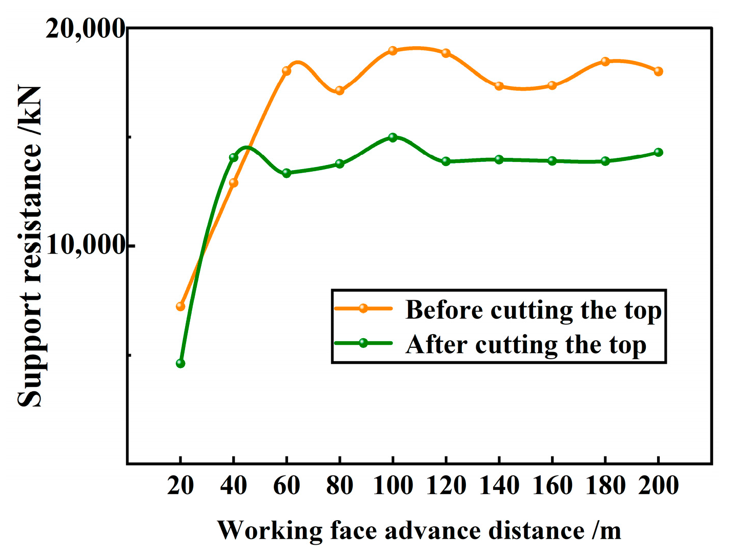
The overhanging distance of the thick hard top slab in the mining hollow area can be effectively reduced by 40.15% thanks to pre-cracking roof cutting, which also reduces the stress concentration degree by 31.74% and the overall stress level of the hydraulic bracket by 26.59–28.38%, according to numerical simulation results. This significantly raises the thick hard top slab just above the working face’s incoming pressure intensity.
(5)
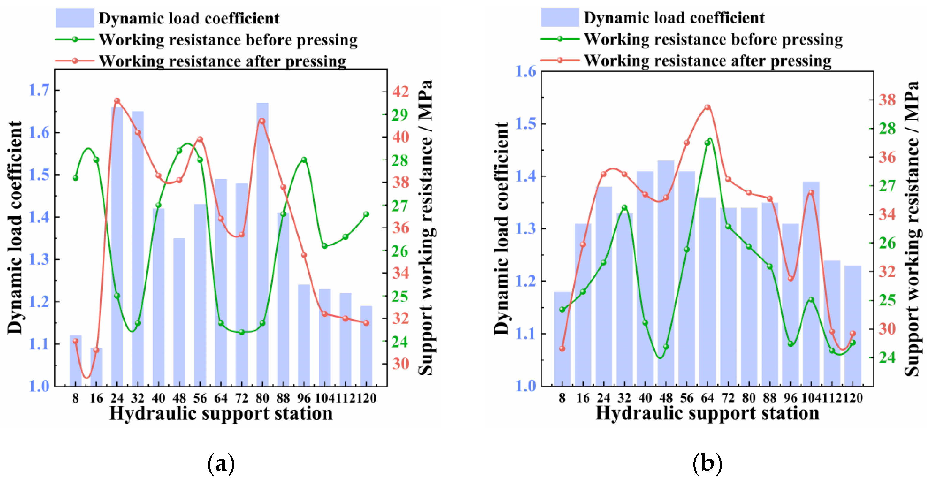
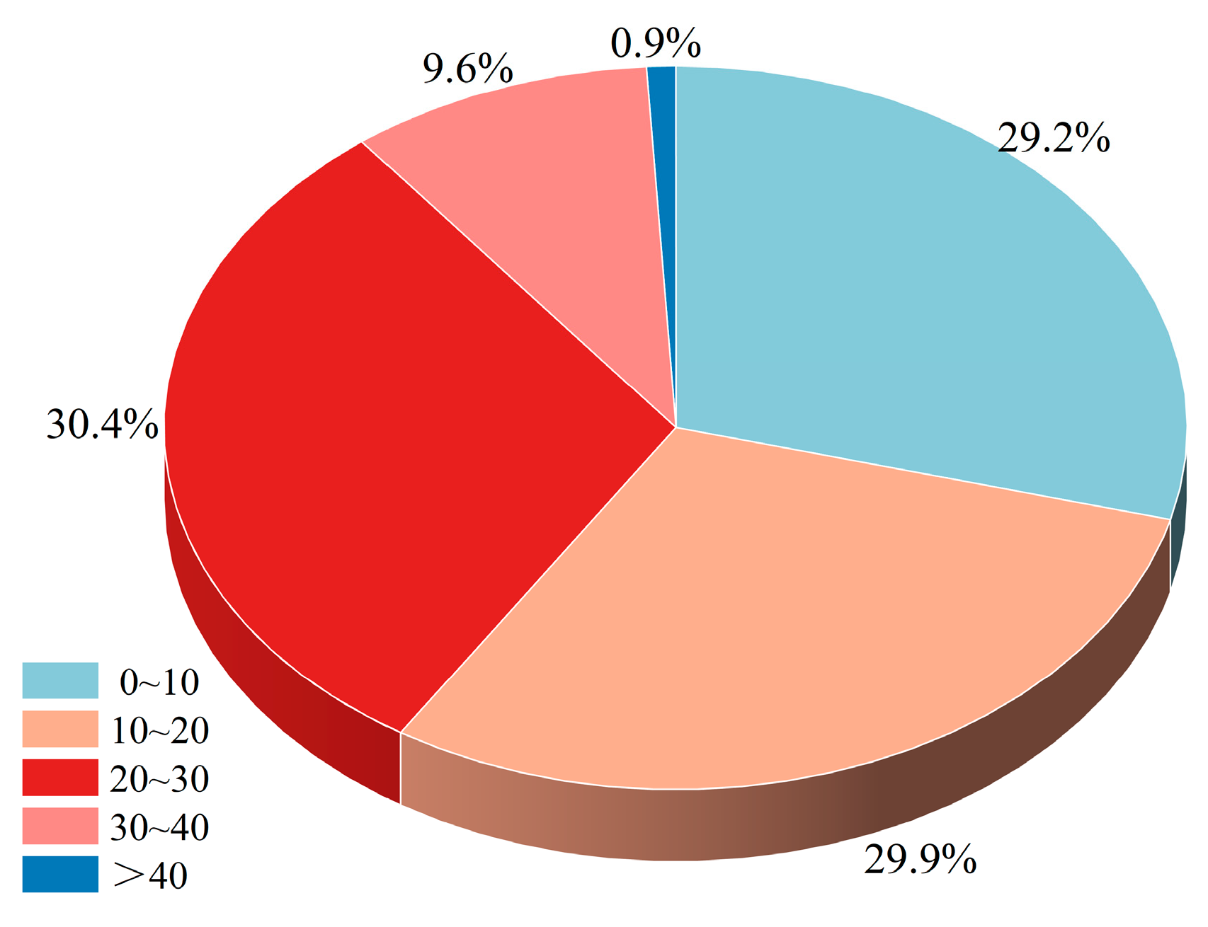
After cutting the roof, the initial pressure step was 40.8 m, the pressure dynamic load coefficient was 1.43, the cycle step was 19.6 m, the pressure dynamic load coefficient was 1.33, and the hydraulic bracket working resistance was only 0.9% in the pressure bracket hydraulic valve. These measurements are combined with site engineering practice and an analysis of the monitoring results. To meet the demands for safe production at the working face of the Gubei Mine in the situation of a direct covered thick hard roof, the working face chooses the ZZ13000/24/50 support cover type brace with a 20 m step pre-cracking roof cutting.

Author Contributions

Conceptualization, J.L., B.F., Q.Z. and Q.B.; methodology, J.L., B.F. and Q.B.; software, J.L.; validation, B.F., Q.Z. and Q.B.; formal analysis, J.L., Q.Z. and Q.B.; investigation, J.L., B.F. and Q.Z.; resources, J.L., B.F., H.Z. and Q.Z.; data curation, J.L., B.F. and Q.Z.; writing—original draft preparation, J.L.; writing—review and editing, J.L., B.F., H.Z., Q.Z. and Q.B.; visualization, J.L., B.F., Q.Z. and Q.B.; supervision, B.F., Q.Z. and Q.B.; project administration, B.F., Q.Z. and Q.B. All authors have read and agreed to the published version of the manuscript.

Funding

This research received no external funding.

Data Availability Statement

Not applicable.

Conflicts of Interest

The authors declare no conflict of interest.

References

  1. Wang, G.; Xu, Y.; Ren, H. Intelligent and ecological coal mining as well as clean utilization technology in China: Review and prospects. Int. J. Min. Sci. Technol. 2019, 29, 161–169. [Google Scholar] [CrossRef]
  2. Zhang, P.; Li, F.; Zhu, H.; Niu, H.; Li, X. Statistical analysis and prevention countermeasures of coal mine accidents from 2008 to 2020. Min. Saf. Environ. Prot. 2022, 49, 128–134. [Google Scholar]
  3. Mu, L.; Bian, X.; Yang, D. Analysis of the causes and safety management measures of roof accidents in mining engineering. China Met. Bull. 2020, 9, 14–15. [Google Scholar]
  4. Li, L.; Ouyang, Y. Study on Safety Management Assessment of Coal Mine Roofs Based on the DEMATEL-ANP Method. Front. Earth Sci. 2022, 10, 891289. [Google Scholar] [CrossRef]
  5. He, Z.; Lu, C.; Zhang, X.; Guo, Y.; Meng, Z.; Xia, L. Numerical and Field Investigations of Rockburst Mechanisms Triggered by Thick-Hard Roof Fracturing. Rock Mech. Rock Eng. 2022, 55, 6863–6886. [Google Scholar] [CrossRef]
  6. Wang, W.; Cheng, Y.; Wang, H.; Liu, H.; Wang, L.; Li, W.; Jiang, J. Fracture Failure Analysis of Hard-Thick Sandstone Roof and its Controlling Effect on Gas Emission in Underground Ultra-Thick Coal Extraction. Eng. Fail. Anal. 2015, 54, 150–162. [Google Scholar] [CrossRef]
  7. Ünver, B.; Yasitli, N.E. Modelling of strata movement with a special reference to caving mechanism in thick seam coal mining. Int. J. Coal Geol. 2006, 66, 227–252. [Google Scholar] [CrossRef]
  8. Zheng, Z.; Xu, Y.; Li, D.; Dong, J. Numerical Analysis and Experimental Study of Hard Roofs in Fully Mechanized Mining Faces under Sleeve Fracturing. Minerals 2015, 5, 758–777. [Google Scholar] [CrossRef]
  9. Ma, J.; Guan, J.; Duan, J.; Huang, L.; Liang, Y. Stability analysis on tunnels with karst caves using the distinct lattice spring model. Undergr. Space 2020, 6, 469–481. [Google Scholar] [CrossRef]
  10. Huang, L.; Ma, J.; Lei, M.; Liu, L.; Lin, Y.; Zhang, Z. Soil-water inrush induced shield tunnel lining damage and its stabilization: A case study. Tunn. Undergr. Space Technol. 2020, 97, 103290. [Google Scholar] [CrossRef]
  11. Ma, J.; Chen, J.; Chen, W.; Huang, L. A coupled thermal-elastic-plastic-damage model for concrete subjected to dynamic loading. Int. J. Plast. 2022, 153, 103279. [Google Scholar] [CrossRef]
  12. Zheng, K.; Zhang, T.; Zhao, J.; Liu, Y.; Yu, F. Evolution and management of thick-hard roof using goaf-based multistage hydraulic fracturing technology—A case study in western Chinese coal field. Arab. J. Geosci. 2021, 14, 876. [Google Scholar]
  13. Tang, J.; Liu, H.; Chen, A. Experimental Study on Presplitting Blasting of Roof Cutting Along Goaf with Thick and Hard Roof Plate. IOP Conf. Ser. Earth Environ. Sci. 2021, 692, 022089. [Google Scholar] [CrossRef]
  14. Zhang, C.; Zou, J.; Zhang, X.; Wang, C.; Jiao, Y. Study on the Mechanism of Weakening Thick and Hard Roof by Deep-Hole Blasting in Deep Coal Mines. Front. Earth Sci. 2022, 10, 933192. [Google Scholar] [CrossRef]
  15. Chen, B.; Liu, C.; Wang, B. A case study of the periodic fracture control of a thick-hard roof based on deep-hole presplitting blasting. Energy Explor. Exploit. 2022, 40, 279–301. [Google Scholar] [CrossRef]
  16. Chen, B.; Liu, C. Analysis and Application on Controlling Thick Hard Roof Caving with Deep-Hole Position Presplitting Blasting. Adv. Civ. Eng. 2018, 2018, 9763137. [Google Scholar] [CrossRef]
  17. Xu, J.; Pu, H.; Sha, Z. Mechanical behavior and decay model of the sandstone in Urumqi under coupling of freeze–thaw and dynamic loading. Bull. Eng. Geol. Environ. 2021, 80, 2963–2978. [Google Scholar] [CrossRef]
  18. Zhao, C.; Liu, J.; Lyu, C.; Chen, W.; Li, X.; Li, Z. Experimental study on mechanical properties, permeability and energy characteristics of limestone from through-coal seam (TCS) tunnel. Eng. Geol. 2022, 303, 106673. [Google Scholar] [CrossRef]
  19. Wang, G.; Pang, Y. Relationship between hydraulic support and surrounding rock coupling and its application. J. China Coal Soc. 2015, 40, 30–34. [Google Scholar]
  20. Wang, G.; Pang, Y. Shield-roof adaptability evaluation method based on coupling of parameters between shield and roof strata. J. China Coal Soc. 2016, 41, 1348–1353. [Google Scholar]
  21. Miao, X.; Qian, M. Overall mechanical model and analysis of the surrounding rock—Support in a header mining site. Coal 1998, 6, 1–5+13. [Google Scholar]
  22. Qian, M.; Miao, X.; He, F.; Liu, C. Study on the mechanism of coupling action between quarry support and surrounding rock. J. China Coal Soc. 1996, 1, 40–44. [Google Scholar]
  23. Xu, Y.; Wang, G.; Ren, H. Theory of the coupling relationship between surrounding rocks and powered support. J. China Coal Soc. 2015, 40, 2528–2533. [Google Scholar]
  24. Wang, D.; Zeng, X.; Wang, G.; Li, R. Adaptability Analysis of Four-Leg Hydraulic Support with Large Mining Height under Impact Dynamic Load. Shock Vib. 2022, 2022, 2168871. [Google Scholar] [CrossRef]
  25. Marcin, W.; Stanisław, P. Numerical calculations of shield support stress based on laboratory test results. Comput. Geotech. 2016, 72, 74–88. [Google Scholar]
  26. Qian, M.; Xu, J.; Wang, J. Mine Pressure and Rock Control, 3rd ed.; China University of Mining and Technology Press: Xuzhou, China, 2021; pp. 121–158. [Google Scholar]
  27. Li, J.; Fu, B. Pressure relief technology of thick hard sandstone directly covering roof. Coal Eng. 2022, 54, 101–107. [Google Scholar]
  28. Xu, Y.; Wang, G. Supporting principle and bearing characteristics of hydraulic powered roof support groups. Chin. J. Rock Mech. Eng. 2017, 36, 3367–3373. [Google Scholar]
  29. Xu, Z. Elasticity(Volume II), 5th ed.; Higher Education Press: Beijing, China, 2016; pp. 68–76. [Google Scholar]
  30. Xu, Y.; Wang, G.; Zhang, J.; Ren, H.; Li, D. Theory and Application of Supporting Stress Fields of Hydraulic Powered Support Groups in Fully mechanized Mining Face with Large Mining Height Based on Elastic Supporting Beam Model. Chin. J. Rock Mech. Eng. 2018, 37, 1226–1236. [Google Scholar]
  31. Chen, S.; He, M.; Guo, Z.; Yang, H.; Yang, J. Control Countermeasures of Surrounding Rock in Deep Gob-Side Entry Retaining by Cutting Roof. Adv. Eng. Sci. 2019, 51, 107–116. [Google Scholar]
Figure 1. Relationship curve between Pe and L.
Applsci 13 02546 g001
Figure 2. Similar physical experiment platform and rock stratum histogram.
Applsci 13 02546 g002
Figure 3. Cut falling body “Simple support—Free” structure: (a,b) are, respectively, the forms of roof cut falling body when the model is excavated to different distances.
Applsci 13 02546 g003
Figure 4. Pre-split roof structure: (a) the overburdened structure after using UDEC software to pre-split and cut a thick, hard roof; (b) the fracture development effect at a depth of 7.8 m; and (c) the crack development effect at a depth of 14.85 m.
Applsci 13 02546 g004
Figure 5. Mechanical model of the CSCF plate.
Applsci 13 02546 g005
Figure 6. Roof deflection surface.
Applsci 13 02546 g006
Figure 9. Schematic diagram of top cutting of a directly covered thick hard roof: (a) Schematic diagram of the overall effect of top cutting; (b) The top view effect diagram of the working face top cutting scheme; (c) A schematic cross-sectional view of the top cutting scheme.
Applsci 13 02546 g009
Figure 10. Displacement cloud image before cutting top: (a) is the displacement state when the working face is first broken when the top is not cut; (b) is the displacement state when the working face is excavated for 120 m when the top is not cut; (c) is the displacement state when the working face is excavated for 160 m when the top is not cut; and (d) is the displacement state when the working face is excavated for 200 m when the top is not cut.
Applsci 13 02546 g010
Figure 11. Displacement cloud image after cutting the roof: (a) is the displacement state when the working face is first broken after cutting the roof; (b) is the displacement state when the working face is excavated for 120 m after cutting the roof; (c) is the displacement state when the working face is excavated for 160 m after cutting the roof; and (d) is the displacement state when the working face is excavated for 200 m after cutting the roof.
Applsci 13 02546 g011
Figure 12. Variations in the stress cloud diagram: (a) is the stress state when the working face is first broken when the roof is not cut; (b) is the stress state when the working face is excavated for 100 m when the roof is not cut; (c) is the stress state when the working face is excavated for 160 m when the roof is not cut; (d) is the stress state when the working face is excavated for 200 m when the roof is not cut; (e) is the stress state when the working face is excavated for 60 m after cutting the roof; (f) is the stress state when the working face is broken for the first time after cutting the roof; (g) is the stress state when the working face is excavated for 60 m after cutting the roof; and (h) is the stress state when the working face is excavated for 200 m after cutting the roof.
Applsci 13 02546 g012aApplsci 13 02546 g012b
Figure 13. Force comparison of support before and after cutting the roof.
Applsci 13 02546 g013
Figure 14. Roof cycle to pressure step statistics: (a) is the upper working face periodic pressure step; (b) is the middle working face periodic pressure step; and (c) is the lower working face periodic pressure step.
Applsci 13 02546 g014
Figure 15. Change of support resistance and dynamic load coefficient: (a) is the change curve of dynamic load coefficient of each station stand when the initial pressure comes after the roof is cut; and (b) is the change curve of dynamic load coefficient of each station stand when the pressure comes periodically after the roof is cut.
Applsci 13 02546 g015
Figure 16. Support resistance frequency statistics.
Applsci 13 02546 g016
Table 1. Basic top classification index table.
Basic Top ClassificationAppearance of Basic Top PressureGrading Index
Level INot obviousPe ≤ 895
Level IIObvious895 < Pe ≤ 975
Level IIIStrong975 < Pe ≤ 1075
Level IVVery strongLevel IVa1075 < Pe ≤ 1145
Level IVbPe > 1145
Table 2. Physical and mechanical parameters of rock strata.
LithologyH
(m)
γ
(kN/m3)
φ
(°)
E
(GPa)
σb
(MPa)
Medium sandstone8.226.231°24 GPa6.50 MPa
Sandy mudstone1.725.629°11 GPa2.47 MPa
Fine sandstone6.226.836°29 GPa7.21 MPa
Sandy mudstone5.225.629°11 GPa2.47 MPa
Fine sandstone11.626.836°29 GPa7.21 MPa
Upper coal seam3.81420°1 GPa2.00 MPa
Lower coal seam41420°1 GPa2.00 MPa
Sandy mudstone2.325.629°11 GPa2.47 MPa
Silty sand rock5.426.133°24 GPa6.20 MPa
Siltstone7.226.733°25 GPa6.60 MPa
Table 3. Monitoring sub-station corresponding location.
Station No.123456789101112131415
Support No.81624324048566472808896104112120
Working surface areaUpper part of working faceMiddle of working faceLower part of working face
Table 4. Statistics of the initial incoming pressure step of the roof.
Monitoring PositionSupport No.Working Face Retreat/mRemarks
Upper part of working face831.1Kerf width
8.5 m
16
24
32
40
Middle of working face4832.6
56
64
72
80
Lower part of working face8833
96
104
112
120
Initial pressure step40.8
Disclaimer/Publisher’s Note: The statements, opinions and data contained in all publications are solely those of the individual author(s) and contributor(s) and not of MDPI and/or the editor(s). MDPI and/or the editor(s) disclaim responsibility for any injury to people or property resulting from any ideas, methods, instructions or products referred to in the content.

