Article

Experimental Analysis of Pressure Relief Effect of Surrounding Rock in High-Stress Roadways under Different Drilling Parameters

1
School of Resources, Environment and Safety Engineering, Hunan University of Science and Technology, Xiangtan 411201, China
2
Key Laboratory of Disaster Prevention and Control of Coal Mine Gas and Roof Plate in Southern China, Xiangtan 411201, China
3
Hunan Provincial Key Laboratory of Coal Mine Safety Mining Technology, Hunan University of Science and Technology, Xiangtan 411201, China
4
Guizhou Panjiang Refined Coal Co., Ltd., Liupanshui 553536, China
5
Institute of Mining Engineering, Guizhou lnstitute of Technology, Guiyang 550003, China
*
Author to whom correspondence should be addressed.
Appl. Sci. 2023, 13(4), 2511; https://doi.org/10.3390/app13042511
Submission received: 16 January 2023 / Revised: 9 February 2023 / Accepted: 12 February 2023 / Published: 15 February 2023
(This article belongs to the Special Issue Mining Safety: Challenges & Prevention)

Abstract

:
Drilling to relieve pressure is a simple and efficient solution to prevent impact ground pressure for the engineering problem of the high risk of impact on the surrounding rock of high stress roads, and choosing suitable drilling parameters is the key to it. The unloading law of borehole diameter, depth, and spacing was investigated using a combination of indoor tests, numerical simulations, and theoretical analysis. The characteristics of crack extension and plastic zone changes of the three were analyzed, and the relationship between boreholes and elastic strain energy was derived by developing a hole mechanics model. The findings indicate that as drilling radius and depth are increased, peak strength and the elastic strain energy stored in front of the peak decrease, the plastic zone around the hole and the main control crack on the surface of the block expand more obviously, and the vertical stress at the top and bottom of the hole decrease, and the peak stress increases with the depth of the hole. The plastic zone surrounding the hole is attached to one another more easily the closer the drilling spacing is. The test block is changed from independent damage to penetrating damage when the drilling spacing is less than or equal to 3.286 cm. However, the pressure release effect does not necessarily improve with narrower drilling spacing. The plastic zone radius and the elastic strain energy held in the rock body are linked to each other linearly and quadratically, respectively, by the drilling radius. The joint pressure relief of several holes should be prioritized when drilling pressure is relieved, and then the hole’s diameter should be increased, and, finally, the hole’s depth should be increased. A reference for engineering applications is provided by this.

1. Introduction

The risk of an impact ground pressure catastrophe increases when coal resource extraction increasingly moves to a deeper area with more complicated circumstances [1,2]. As a traditional method of impact ground pressure prevention and management, borehole pressure relief offers the benefits of easy operation, cheap cost, and immediate relief [3,4].
Numerous academics have studied the strength change, stress transmission, and energy release in drilled coal rock masses for a very long period [5,6,7]. In terms of the drilled coal rock mass’s strength fluctuation, when unloading pressure in boreholes, Y.L. et al. [8] and D.G. et al. [9] used numerical software to study the relationship between relevant parameters. The results show that there is no linear relationship between borehole diameter and pressure relief effect. It is recommended to select a reasonable borehole diameter and borehole spacing. Additionally, reference [10] and P.X. et al. [11] studied the influence factors of different drilling parameters on the pressure relief effect. The results show that the amount of rock crack propagation increases with the increase in borehole diameter and the decrease in borehole spacing, but the borehole diameter being too large may cause a rock burst. For stress transfer after drilling in coal seam rock masses, Z.C. et al. [12] studied the influence of drilling location and drilling depth on the pressure relief effect of surrounding rock by numerical simulation. The research shows that with the increase in drilling depth, the stress of the surrounding rock shifts to the inside, and the stress near the surrounding rock gradually decreases. However, the pressure relief effect is not proportional to the drilling depth. J.Z. et al. [13] showed that through drilling mechanics analysis and numerical simulation, the borehole unloading effect is obvious in the plastic–elastic zone and the elastic–elastic zone, and the unloading stress is the normal distribution. H.Z. et al. [14] and Z.L. et al. [15] studied the drilling pressure relief and surrounding rock control technology of deep roadways: drilling pressure relief technology can effectively release the elastic potential energy of shallow high-stress surrounding rock, which will make the shallow high stress transfer to the deep, thus reducing the difficulty of the roadway’s support. Studies on the energy release of borehole coal mass by J.Z. et al. [16] and S.G. et al. [17] showed the strain energy variation of rock mass around the borehole. The results show that the drilling pressure relief technology reduces the strength of the rock mass and the stored strain energy to a certain extent, which effectively reduces the impact risk. W.Z. et al. [18,19] proposed an innovative monitoring method while drilling, The results show that the drilling depth can be obtained by calculating the number of amplitude clusters, and the number of coal vibration events generated during drilling can evaluate the pressure relief degree of a single hole.
In summary, domestic and foreign scholars have undertaken a lot of research on borehole diameter and borehole spacing as well as borehole depth and borehole spacing, and they have achieved rich results. However, few scholars have studied the peak strength of rock mass and its transfer, plastic zone radius, and energy under different borehole diameters, borehole depths, and borehole spacing. Therefore, this paper studies the influence of rock mass strength, stress transfer, plastic zone, and elastic strain energy on pressure relief through different drilling parameters. It is expected that this can provide some theoretical guidance for the prevention and control of rock bursts in the surrounding rock of high-stress roadways.

2. Test Scheme and Test Steps

In this experiment, cement and fine sand were used to make test blocks to simulate the mechanical properties of coal rock. The mass ratio of water:cement:fine sand is 1.1:1.67:5.01, and the cement model is M32.5 gray cement. The materials are stirred well according to the ratio above and loaded into the mold. The tube is then inserted into the appropriate place in the abrasive, which is used to prepare the hole. The test block was demolded after 24 h of production. The test block after demolding is cured according to the following concrete curing criteria: watering three times a day under indoor natural conditions, the test block staying moist for no less than 6 min (this operation lasts for at least one week), and curing for 28 days. The test block size is a cube with a side length of 150 mm.
The purpose of this experiment is to explore the influence of different borehole diameters, borehole depths, and borehole spacing on the pressure relief effect. An RMT-150C rock mechanics servo testing machine is used in the test, as shown in Figure 1a, and the pressure control rate is 0.5 N/s. The peak strength and stress–strain curves of the test block were tested by uniaxial compression to analyze the influence of different parameters on pressure relief. In order to reduce the ’end effect’ when the test block is pressurized, the two ends of the test block are polished before the uniaxial compression test. Some test blocks are shown in Figure 1b, and lubricant is applied between the test block and the pressure plate. The whole process of the test block from the beginning of pressurization to failure is recorded in real time to observe the generation, expansion, and penetration of the initial surface cracks of the test block. The specific test scheme is shown in Table 1 below. Three test blocks were prepared in each group, and the discreteness of strength in each group was analyzed, the group of tests with a dispersion coefficient greater than 0.3 is supplemented, and then the test block data with a large deviation from the average value is deleted. This ensures that the data results of at least two test blocks in each group are similar, and then one of them is selected for research and analysis. According to the calculation results of the peak strength dispersion coefficient of the test block, the strength dispersion coefficient intervals of different borehole diameters, depths, and spacings are [0.032, 0.205], [0.062, 0.205], and [0.042, 0.147], respectively.

3. Test Results Analysis

The peak strength and stress–strain curves of different drilling parameters were tested by a uniaxial test, and the strain energy accumulated before the peak of the test block was approximately calculated by the stress–strain curve, and then the influence on the pressure relief effect was analyzed according to the changes of the three. The strain energy is stored in the object in the form of stress and strain. The more strain energy is stored before the peak, the more energy is released in the post-peak failure stage; this is the fundamental factor of rock mass impact failure [20].

3.1. Stress–Strain Analysis under Different Apertures

The peak strength, stress–strain, and elastic strain energy curves of the test blocks with different borehole diameters after uniaxial compression (the test blocks without holes and the test blocks with borehole diameters of 6, 10, 15, 20, 25, and 40 mm are replaced by numbers 0, 6, 10, 15, 20, 25, and 40 in Figure 2b) are shown in Figure 2. From Figure 2a and Table 2, it can be seen that compared with the complete test block, with the increase in the diameter of the borehole test block, the peak strength and strain value decrease to varying degrees.
Combined with the pre-peak cumulative strain energy curve in Figure 2b, it can be seen that as the borehole diameter increases, the peak strength is similar to the strain image at the peak stress and shows a decreasing trend. The elastic strain energy stored before the peak of the test block decreases with the increase in the borehole diameter. When the borehole diameter is 6 mm and 10 mm, the peak strength of the test block decreases slightly; when the borehole diameter increases to 15 mm, the peak strength of the test block suddenly decreases greatly, and the reduction percentage is more than three times that of the former. This is because the optimal pressure relief critical value is achieved when the borehole diameter is 15 mm, resulting in a sharp drop in the strength of the test block. However, when it increases to 20 and 25 mm, the peak strength and pre-peak accumulated strain energy tend to be stable.

3.2. Stress–Strain Analysis under Different Hole Depths

From Figure 3 (in Figure 3a, the non-hole test block and the test block with drilling depths of 3, 6, 9, 12, and 15 cm are replaced by the numbers of 0, 3, 6, 9, 12, and 15, respectively.) and Table 3, which compared the test blocks without holes, as the drilling depth gradually increases, the peak strength of the test blocks decreases and the strain at the peak stress decreases.
It can be seen that when the drilling depth increases from 9 cm to 12 cm, the strength increases. According to the source mechanism of the rock burst, the occurrence of the rock burst is caused by the close distance between the free surface and the source. The deeper the borehole is, the closer the free surface is to the source. When the hole depth is greater than the critical value between the two, the stress wave will have an impact on the surrounding rock of the roadway [21]. This is also the reason why the peak strength of the test block does not decrease when the drilling depth is from 9 cm to 12 cm. When the stress peak is 15 cm, the strain value decreases greatly. This is because the hole runs through the whole test block, and the stress at both ends is evenly distributed. Compared with the non-penetrating test block, the bearing capacity of the latter part decreases, resulting in a smaller strain value. Combined with the strain energy curve accumulated before the peak in Figure 3b, it can be seen that with the increase in drilling depth, the peak strength is similar to the strain image change at the peak stress, and the elastic strain energy accumulated before the peak of the test block is reduced.

3.3. Stress–Strain Analysis under Different Hole Spacing

From the reduction ratio of the peak strength and strain value in Table 4, it can be seen that compared with the non-porous sample, the peak strength and strain value of the test block decrease to varying degrees with the decrease in the borehole spacing.
According to the strain diagram at the peak stress in Figure 4a, it can be seen that the peak strength is similar to the strain image at the peak stress as the borehole spacing decreases and gradually decreases. When the drilling spacing is reduced from 4 cm or 5 cm to 3 cm, the peak intensity is greatly reduced. However, when the hole spacing is reduced to 1 cm, the rock mass strength and the strain at the peak stress increase instead. This shows that the hole spacing is not the smaller the better; the hole spacing is too small to approximate single-hole pressure relief.
According to the influence of the borehole diameter, borehole depth, and double holes on the rock mass strength, it can be seen that the pressure relief effect of double holes is more obvious than that of a single hole, and the pressure relief effect of expanding aperture is more obvious than that of increasing hole depth. Therefore, the reasonable arrangement of drilling parameters can not only improve the efficiency of pressure relief but also maintain the stability of roadways.

4. Description and Numerical Analysis of Failure Characteristics of Test Block

In order to further analyze the influence of different drilling parameters on pressure relief, the crack propagation on the surface of the test block and the change law of the plastic zone around the hole are analyzed, respectively. The plastic zone formed around different drilling parameters is different. The larger the plastic zone, the higher the damage degree of the rock mass, and the more favorable the pressure relief around the borehole. The change in the plastic zone around the hole is obtained by FLAC simulation software. The bottom of the numerical model is fixed, and the force is applied to the top. When the calculation model reaches equilibrium, the calculation stops. This is the distribution law of the plastic zone of the borehole rock mass under the uniaxial action of the simulated laboratory test. Due to space reasons, this paper only shows the simulation of vertical stress of the aperture and hole depth. The simulated mesoscopic parameters are based on the physical quantities measured by the complete specimen, as shown in Table 5. In the simulation process, the free surface, the bottom fixed load, the top applied load, and the load were loaded in the form of force to simulate the effect of a uniaxial compression test.

4.1. Breakage and Numerical Analysis of Test Block under Different Apertures

As shown in Figure 5, the failure of the test block with different borehole diameters shows that the failure of the test block is mainly crack propagation, surface shedding, and hole wall collapse. By observing the whole process of the failure of the test block under uniaxial compression, during the failure process of the test block with different apertures, a tensile microcrack first appears above the hole, and as the axial stress continues to increase, the tensile crack extends along the axial direction, forming a crack through the hole. After entering the stress peak stage, the micro-cracks on the surface of the test block begin to increase, and, finally, the main control crack propagation test block was quickly and completely destroyed [22]. From the failure state of the test blocks with different apertures in Figure 5, the surface of the test blocks with apertures of 6 mm and 10 mm (such as Figure 5a,b) presents slight shedding, the crack propagation is not obvious, the damage degree is low, and the hole wall collapse is not obvious. The surface of the test block with borehole diameters of 15 mm, 20 mm, and 25 mm (Figure 5c–f) showed obvious shedding, and the main control crack propagation, damage degree, and hole wall collapse gradually became obvious. Combined with FLAC3D simulation Figure 6, Figure 7 and Figure 8, and the vertical stress values of the monitoring points in Figure 7 from the shallow to the deep are counted in Figure 8a,b, respectively. It can be seen that with the increase in pore size, the radius of the plastic zone around the hole is larger, and the vertical stress at both ends of the hole, top and bottom, gradually decreases, but there is a peak stress concentration not far from the borehole.

4.2. Rupture and Numerical Analysis of Test Block under Different Hole Depths

Figure 9 shows the failure diagram of test blocks with different drilling depths. The results show that the failure process of the test block with different hole depths is basically the same as that of the hole diameter. As the axial stress continues to increase, the micro-cracks generated around the hole increase, which leads to the acceleration of the main control crack propagation, and the test block is quickly and completely destroyed. From the failure state of the test block in Figure 9, the number of micro-cracks in the test block with a hole depth of 3 mm and 6 mm (such as Figure 9a,b) is relatively large, the main control crack propagation is not clear, the hole wall is retained intact, and the surface shedding is not obvious. The main control crack propagation, hole wall collapse, and surface shedding on the surface of the test block with depths of 9 mm, 12 mm, and 15 mm (Figure 9c–e) become more and more obvious, and the degree of damage also increases. Combined with the FLAC3D simulation in Figure 8, Figure 9, Figure 10 and Figure 11, it can be seen that the deeper the drilling hole, the larger the radius of the plastic zone around the hole, and the smaller the vertical stress value at both ends of the top and bottom of the hole, but the vertical stress value does not decrease significantly. It can be seen from Figure 8b that as the hole depth increases, the stress peak above the hole shifts deeper.
According to the experimental and numerical analysis results of different pore diameters and depths, it can be seen that the larger the borehole diameter, the smaller the peak strength and the larger the plastic zone range, which leads to more obvious main crack propagation. The larger the aperture is, the smaller the vertical stress value at both ends of the top and bottom of the hole is, but there is still a concentration of peak stress not far from the borehole, which indicates that the borehole pressure relief can only unload the stress around the borehole. With the increase in drilling depth, the vertical stress values at both ends of the top and bottom of the hole decrease slightly, and the strength decreases not obviously, indicating that the pressure relief efficiency of the hole depth is smaller than that of the hole diameter, and the larger the hole depth, the more the peak stress is transferred to the deep part.

4.3. Test Block Breaking and Numerical Analysis under Different Hole Spacing

As shown in Figure 12, the failure patterns of test blocks with different borehole spacing are also different. The failure modes of the test blocks with borehole spacing of 1 cm, 2 cm, and 3 cm (as Figure 12a–c) are as follows: (1) Penetration failure. The specific performance that there are cracks between the two boreholes. Due to the small distance between the two pressure relief holes, the interaction ability is strong, and the extended cracks are easy to intersect. The failure modes of the test block with a spacing of 4 cm and 5 cm (Figure 12d,e) are as follows: (2) Independent failure, which is manifested as no cracks between the two boreholes. This is because the distance between the two pressure relief holes is large, the interaction ability is weak, and the formed crack propagation is not easy to intersect. Under uniaxial compression, it is similar to the force of two separate holes, and the failure form is similar to the failure of a separate hole (in line with the conclusion of reference [23]). With the decrease in drilling spacing, the crack spacing above the hole decreases gradually. According to Figure 13, when the drilling spacing is 1 cm, 2 cm, and 3 cm, the plastic zone around the two boreholes is connected; when the borehole spacing is 4 cm and 5 cm, the plastic zones around the two boreholes are independent of each other, which conforms to the failure mode of the indoor test block. Due to the length of the paper, the stress of the simulated borehole spacing and its monitoring diagram are not displayed. The simulation results show that as the borehole spacing decreases, the stress above the borehole is smaller; that is, the pressure relief effect is more obvious. However, when the borehole spacing is reduced to 1 cm, the stress increases, which is consistent with the indoor test results. This shows that there is a critical value of borehole spacing, not the smaller the spacing, the better the pressure relief effect.
Based on the above, there is no linear relationship between the parameters of the three different boreholes and the pressure relief effect (consistent with the conclusion of [7]). Moreover, too-large borehole diameter, borehole depth, and borehole spacing will cause problems such as construction difficulties, high cost, and the destruction of the surrounding rock stability. Grasping the best borehole diameter can improve pressure relief efficiency.

5. Drilling Pressure Relief Mechanism

The borehole pressure relief method is to unload the high stress accumulated in the rock mass or change the mechanical properties of the coal rock in the area above the borehole by constructing the borehole. In this way, the coal rock with potential high stress impact failure becomes stable failure or early failure so that the high stress goes deep into the deep surrounding rock so as to reduce the impact risk of surrounding rock in high-stress roadways [24]. After the surrounding rock of the high-stress roadway is drilled, a plastic zone larger than the aperture is generated around each borehole. The plastic zones formed by multiple boreholes are interconnected to form a large-scale plastic zone. On the one hand, under the condition of high stress, the coal rock in this area is destroyed; therefore, the peak stress is transferred to the deep part of the surrounding rock, and the impact risk is reduced; on the other hand, the stress concentration of coal rock above the plastic zone decreases, resulting in the change of coal rock properties. Additionally, the accumulated elastic strain energy in coal rock decreases, and the impact tendency of the roadway’s surrounding rock decreases, thus playing the role of pressure relief [25].

5.1. Borehole Mechanics Model Establishment and Pressure Relief Analysis

The three-dimensional rectangular coordinate system (x, y, z) and the two-dimensional polar coordinate system (ρ, θ) are established as the auxiliary coordinate system of the drilling mechanics model, as shown in Figure 14. In order to simplify the calculation, it is assumed that the internal force of the rock mass is isotropic and the rock mass is an elastic–plastic material. Before the drilling construction, the rock mass of the roadway side is in an elastic state, the stress (p) of the rock mass edge is the confining pressure of the borehole, and the stress (p) is valued according to the distribution law of the abutment pressure (σp) before the drilling in the z-axis direction.
According to the theory of classical mechanics, under the action of equal confining pressure, the rock mass around the hole will form a plastic zone and an elastic zone, and the radial stress expressions of the plastic zone, the elastic zone, and the junction of the two zones are shown as follows [26]:
σ ρ p = σ c ξ 1 ( ρ / R ) ξ 1 1
σ ρ e = σ 1 1 ( r / ρ ) 2 + σ r ( r / ρ ) 2
σ r = ( r ξ 1 / R 1 ) σ c / ( ξ 1 )
In the formula: the radial stress of the rock mass ( σ ρ p ) in the plastic zone (the unit is MPa); the radial stress of rock mass ( σ ρ e ) in the elastic zone (the unit is MPa); ρ is the distance from the point to the center of the borehole in m; ξ is the plastic coefficient of the rock mass; σr is the radial stress at the junction of the two zones, and the unit is MPa; σc is the uniaxial compressive strength of the rock mass (unit is MPa); σ1 is the maximum principal stress in MPa; r is the radius of the plastic zone (unit is m); R is the radius of the borehole in m.
From the plastic zone radius equation in classical mechanics, it can be seen that [27]:
r = R ( p + c cot θ ) ( 1 sin θ ) / ( c cot θ ) 1 sin θ 2 sin θ
In the formula: c is the cohesion of the rock mass, the internal friction angle.
Taking σ1 = p = σp, the radial stress of the rock mass in the elastic zone in the z-axis direction of the borehole is the stress of the rock mass of the two sides of the roadway after unloading above the borehole ( σ p ) [12]:
σ p = σ p 1 ( r / ρ ) 2 + σ r ( r / ρ ) 2
The difference in unloading stress after drilling can be obtained ( Δ σ ) from Equation (5):
Δ σ = σ p σ p = ( σ 1 σ r ) ( r / ρ ) 2
Assuming that the plastic zone of the rock mass is no longer elastic, there is no change in kinetic energy and non-mechanical energy during drilling, and the work performed by external forces is completely converted into strain energy; the strain energy formula of the unit body can be obtained [28]:
ν ε = 1 2 E σ 1 2 + σ 2 2 + σ 3 2 2 μ ( σ 1 σ 2 + σ 2 σ 3 + σ 1 σ 3 )
In the formula: the strain of rock mass; the Poisson’s ratio of rock mass; E is the elastic modulus of the rock mass (unit is MPa); σ1, σ2, and σ3 are the principal stresses in three directions, respectively, and the unit is MPa. It is the elastic strain energy of rock mass (the unit is kJ/m3). Additionally, by substituting σ1 = σ2, σ3 = 0 into Equation (7), the following formula is obtained:
ν ε = σ p ε ( 1 μ ) ( μ < 1 )
Substitute Formula (5) into Formula (8):
ν ε = σ p + σ r σ p r / ρ 2 ε 1 μ
Substituting Equation (4) into Equation (9), we can find:
ν ε = σ p + ( σ r σ p ) ( R / ρ ) 2 ( p + c cot θ ) ( 1 sin θ ) / ( c cot θ ) ( 1 sin θ ) / sin θ ε ( 1 μ )
From Equation (2) minus Equation (3), the following formula is obtained:
σ ρ e σ r = ( σ 1 + σ r ) 1 ( r / ρ ) 2
Based on the definition of strain energy, it can be seen that at this time, the rock mass only considers the stress situation in the elastic range, and then ρ > r, and the substitution (11) has:
σ ρ e > σ r
It can be seen that the stress value in the elastic zone is greater than the stress (σr) value at the elastic and plastic junction (here refers to the stress in the same direction), and it is easy to obtain the following relationship:
σ p > σ r
From Equations (4) and (10), it can be seen that the borehole radius R has a linear relationship with the radius r of the plastic zone around the borehole and has a quadratic relationship with the elastic strain energy stored in the rock mass. If the circular hole is regarded as a roadway, Formulas (3) and (4) show that when the radius R of the roadway and the confining pressure p are constant, the deeper the surrounding rock of the roadway is, the larger the radius r of the plastic region is, and the farther the stress peak goes into the deep surrounding rock, as shown in Figure 15. According to Formulas (9) and (13), the deeper the drilling depth, the larger the radius of the plastic zone around the hole (r), and the smaller the elastic strain energy stored in the rock mass. Combining Equations (10) and (13), it can be seen that if other conditions remain unchanged, the larger the borehole radius r is, the smaller the accumulated elastic strain energy of the rock mass is.
The above discussions are all single-hole pressure relief, whereas, in actual engineering, multiple boreholes are used to relieve pressure together, so it is necessary to discuss the influence of borehole spacing on the pressure relief effect. Taking two boreholes with the same diameter and depth as an example, when the plastic zone formed between the boreholes begins to connect, the strain energy changes fastest and the pressure relief effect changes most obviously [9]. Based on this, in the case of the same diameter and depth of the two boreholes, the radius of the plastic zone of the single borehole is obtained, and then the maximum spacing between the plastic zones of the two boreholes is determined, as shown in Figure 16 (the stress is positive in tension and negative in compression). The parameter values measured by the non-porous test block are p = σ1 = σc = 19.231 MPa, the cohesion of the rock c = 0.5 MPa, and the internal friction angle θ = 27°. Substituting the measured parameter values into Equation (4) to calculate the radius of the single-hole plastic zone, r = 4.286R m, and then the distance between the two boreholes should not be less than ∆d = 2r − 2R = 6.572R. As the hole radius set by the borehole spacing in the laboratory test is R = 0.5 cm, it is calculated that when the spacing between the two boreholes 3.286 cm ≥ ∆d, the plastic zone around the hole is connected, and vice versa.
In summary, construction drilling can unload the high stress in the rock mass and reduce the elastic strain energy stored in the rock mass, thereby achieving the effect of pressure relief. The larger the radius and depth of the borehole, the larger the radius of the plastic zone of the rock mass, and the smaller the strength of the rock mass and the cumulative elastic strain energy, the more the peak stress is transferred to the deep part, and the better the pressure relief effect, which is in line with the test conclusions of 2.1 and 2.2 in the text. When the drilling spacing Δd ≤ 3.286 cm, the plastic zone formed by the two boreholes is connected, the peak strength changes the most, and the pressure relief effect is obvious. The results are in line with the experimental conclusions of 2.3 and 3.3.

5.2. Circumferential Stress Distribution of Unidirectional Stress Circular Hole

The stress state around the hole is changed after the rock mass is drilled, which is the main reason for the tensile failure or shear failure of the rock mass. Therefore, it is particularly important to study the stress state around the borehole and then judge its failure mode. According to the stress distribution formula at the edge of the hole [28]:
σ φ = p 2 1 + ( R / r ) 2 p 2 1 + 3 ( R / r ) 4 cos 2 φ
Take φ = 90 ° , along the y-axis, circumferential normal stress:
σ φ = 1 2 + 3 2 ( R / r ) 2 p ( R / r ) 2
Again φ = 0 ° , along the x-axis, circumferential normal stress:
σ φ = p 1 + 1 2 ( R / r ) 2 + 3 2 ( R / r ) 4
The calculation results of several important values of Formulas (15) and (16) are shown in Table 6. From the results of the stress around the hole calculated in Table 6, it can be seen that there is a maximum tensile stress p in the vertical direction and a maximum compressive stress 3p in the horizontal direction, as shown in Figure 17. Because the test block is composed of cement and fine sand materials, the elastic–plastic material has the mechanical properties of compression but is easy to be destroyed by tension. This is in line with the fact that tensile cracks first appear in the vertical direction along the center of the hole after a period of uniaxial compression of the indoor test block in Section 3, and as the pressure continues to increase, the cracks increase, the main control crack expands, and the test block finally exhibits tensile shear failure.

6. Conclusions

  • The failure of the rock mass around the borehole is the root cause of pressure relief, and the radius of the plastic zone around the borehole is the key factor affecting the failure of the rock mass. With the increase in the drilling radius and drilling depth, the strength of the rock mass and the stored elastic strain energy decrease. The larger the radius of the plastic zone around the hole is, the more obvious the surface main control crack propagation is. Additionally, the vertical stress at both ends of the hole top and bottom becomes smaller, the impact tendency of the surrounding rock of the roadway is reduced, and the pressure relief effect is better.
  • According to the analysis of the percentage reduction in the peak strength of the test block, it can be seen that larger borehole diameters are not better. If the aperture is too large, not only does the pressure relief effect not change significantly, but also the coal wall of the two sides of the roadway will be destroyed and the stability will be reduced. If the hole spacing is too small, it will become single-hole pressure relief, which will lead to an increase in the rock mass strength. The borehole pressure relief can only remove the stress near the borehole, and there is a new peak stress concentration not far from the borehole.
  • The change in borehole spacing has a significant effect on the failure mode of the rock mass. The smaller the spacing between the two holes, the easier the plastic zone around the two holes is to connect, and the rock mass is dominated by penetration failure, whereas the rock mass is dominated by independent failure. Different pressure relief parameters have different pressure relief efficiencies, and the priority should be given to multi-hole combined pressure relief, followed by expanding the aperture, and finally increasing the hole depth.
  • The mechanical model of drilling holes is established by classical mechanics. It is concluded that the radius of the drilled hole has a linear relationship with the radius of the plastic zone around the hole and has a quadratic relationship with the elastic strain energy stored in the rock mass; the deeper the borehole is, the farther the stress peak goes into the deep surrounding rock; when the borehole spacing is less than or equal to 3.286 cm, the plastic zones generated around the two boreholes are connected.

Author Contributions

Conceptualization, P.W., Y.J., P.L., J.Z. and Z.Z.; methodology, P.W., Y.J. and P.L.; software, Y.J. and P.L.; validation J.Z. and Z.Z.; formal analysis, P.W. and Y.J.; investigation, P.L. and J.Z.; writing—original draft preparation, Y.J.; writing—review and editing, P.W. and Y.J.; funding acquisition, P.W. All authors have read and agreed to the published version of the manuscript.

Funding

This work was supported by the National Natural Science Foundation of China (52174110), key projects of the Hunan Provincial Department of Education (21A0313), the key laboratory of the Ministry of Education for Coal Mine Safety and Efficient Mining (JYBSYS2021203), the Hunan Natural Science Foundation (2020JJ5186), and these projects are led by Ping Wang. This article is also funded by the Guizhou province science and technology support plan funded projects, and this project is led by Ze Zhou.

Institutional Review Board Statement

Not applicable.

Informed Consent Statement

Not applicable.

Data Availability Statement

The data presented in this study are available in the article.

Conflicts of Interest

The authors declare no conflict of interest.

References

  1. Zhai, C.; Xu, J.; Liu, S.; Qin, L. Investigation of the discharge law for drill cuttings used for coal outburst prediction based on different borehole diameters under various side stresses. Powder Technol. 2018, 325, 396–404. [Google Scholar] [CrossRef]
  2. Liu, S.; Li, H.; Cheng, G. Numerical and experimental investigation on rock breaking performance with hydraulic splitter. Tunn. Undergr. Space Technol. 2019, 96, 103181. [Google Scholar] [CrossRef]
  3. He, Z.; Gong, F.; Luo, S. Evaluation of the rockburst proneness of red sandstone with prefabricated boreholes: An experimental study from the energy storage perspective. Geomat. Nat. Hazards Risk 2021, 12, 2117–2154. [Google Scholar] [CrossRef]
  4. Lin, H.; Oh, J.; Canbulat, I.; Hebblewhite, B.; Masoumi, H.; Walsh, S. Experimental study on borehole size effect and prediction of breakout initiation stress. Int. J. Rock Mech. Min. Sci. 2021, 142, 104762. [Google Scholar] [CrossRef]
  5. Liu, T.; Lin, B.; Fu, X.; Zhao, Y.; Gao, Y.; Yang, W. Modeling coupled gas flow and geomechanics process in stimulated coal seam by hydraulic flushing. Int. J. Rock Mech. Min. Sci. 2021, 142, 104769. [Google Scholar] [CrossRef]
  6. Gong, F.; He, Z.; Si, X. Experimental study on revealing the mechanism of rockburst prevention by drilling pressure relief: Status-of-the-art and prospects. Geomat. Nat. Hazards Risk 2022, 13, 2442–2470. [Google Scholar] [CrossRef]
  7. Zhang, S.; Li, Y.; Shen, B.; Sun, X.; Gao, L. Effective evaluation of pressure relief drilling for reducing rock bursts and its application in underground coal mines. Int. J. Rock Mech. Min. Sci. 2019, 114, 7–16. [Google Scholar] [CrossRef]
  8. Lan, Y.; Liu, P.; Li, W.; Chen, X.; Lu, Z.; Xing, W. The influencing factors of drillhole pressure relief and the regression analysis of destroy radius. Saf. Coal Mines 2013, 44, 24–26+30. (In Chinese) [Google Scholar]
  9. Ge, D.; Li, D.; Jiang, F. Reasonable pressure-relief borehole spacing in coal of different strength. J. Min. Saf. Eng. 2020, 37, 578–585+593. (In Chinese) [Google Scholar]
  10. Li, Y.; Zhang, H.; Zhu, Z.; Guo, C. Study on safety parameters of pressure relief borehole in rockburst coal seam. China Saf. Sci. J. 2018, 28, 122–128. (In Chinese) [Google Scholar]
  11. Xu, P.; Shao, J.; Fan, D.; Chang, J.; Zhang, N. Analysis of pressure relief effect of borehole in rock burst mine. Energy Rep. 2021, 8, 156–161. [Google Scholar] [CrossRef]
  12. Chen, Z.; Xu, T.; Dai, X.; Song, J. Effect of Borehole Positions and Depth on Pressure Relief of Cavern Surrounding Rock Mass. Geotech. Geol. Eng. 2021, 40, 237–248. [Google Scholar] [CrossRef]
  13. Zhao, J.; Zheng, Z.; Liu, L. Stress field zoning and length optimization design of pressure relief borehole. Min. Saf. Environ. Protect. 2018, 45, 65–68+73. (In Chinese) [Google Scholar]
  14. Zheng, H.; Wang, M.; Xu, S. Research on surrounding rock Pressure relief in deep roadway by borehole and its control technology. Min. Saf. Environ. Protect. 2014, 41, 51–55. (In Chinese) [Google Scholar]
  15. Liu, Z.; Wang, Z.; Zhang, R.; Sun, X.; Wenzheng, S. Study on Rationality of Large Diameter Pressure Relief Drilling Parameters Under Different Coal Seam Conditions. Geotech. Geol. Eng. 2022, 40, 5245–5436. [Google Scholar] [CrossRef]
  16. Zuo, J.; Hu, S.; Zhou, X.; Zhang, C.; Guo, Y. Effective evaluation of pressure relief drilling layout for reducing rock bursts and sensitive factor analysis. Arab. J. Geosci. 2021, 14, 2643. [Google Scholar] [CrossRef]
  17. Gu, S.; Chen, C.; Jiang, B.; Ding, K.; Xiao, H. Study on the Pressure Relief Mechanism and Engineering Application of Segmented Enlarged-Diameter Boreholes. Sustainability 2022, 14, 5234. [Google Scholar] [CrossRef]
  18. Zhang, W.; Li, C.; Jin, J.; Qu, X.; Fan, S.; Xin, C. A new monitoring-while-drilling method of large diameter drilling in underground coal mine and their application. Measurement 2020, 173, 108840. [Google Scholar] [CrossRef]
  19. Zhang, W.; Li, C.; Ren, J.; Wu, Z. Measurement and application of vibration signals during pressure relief hole construction using microseismic system. Measurement 2020, 158, 107696. [Google Scholar] [CrossRef]
  20. Wang, A.; Gao, Q.; Pan, Y. Experimental study of rock burst prevention mechanism of bursting liability reduction-deformation control-energy dissipation based on drillhole in coal seam. Rock Soil Mechan. 2021, 42, 1230–1244. (In Chinese) [Google Scholar] [CrossRef]
  21. Yan, Y.; Zhu, T.; Zhang, B.; Kang, L. Research on the mechanism of impact ground pressure seismic source. J. Taiyuan Univ. Technol. 2010, 41, 227–230. (In Chinese) [Google Scholar] [CrossRef]
  22. Wang, P.; Feng, T.; Zhu, Y.; Yu, W. Fracture experiments on anchoring ordered multi-crack body in rock-like materials under uniaxial compression. Chin. J. Geotech. Eng. 2015, 37, 1644–1652. [Google Scholar] [CrossRef]
  23. Jia, C.; Jiang, Y.; Zhang, X.; Wang, D.; Luan, H.; Wang, C. Laboratory and numerical experiments on pressure relief mechanism of large-diameter boreholes. Chin. J. Geotech. Eng. 2017, 39, 1115–1122. (In Chinese) [Google Scholar]
  24. Wang, S.; Pan, J.; Shaohong, L.; Xia, Y.X.; Gao, X.J. Evaluation method for rockburst-preventing effects by drilling based on energy-dissipating rate. Ournal China Coal Soc. 2016, 41, 297–304. (In Chinese) [Google Scholar] [CrossRef]
  25. Zhang, L.; Cheng, G.; Gong, C. Analysis on surrounding rock characteristics of pressure relief borehole based on damage theory. Saf. Coal Mines 2019, 50, 226–230. (In Chinese) [Google Scholar]
  26. Tan, Y.; Wu, S.; Yin, Z. Mine Pressure and Strata Control; Coal Industry Press: Beijing, China, 2008; pp. 32–36. (In Chinese) [Google Scholar]
  27. Cai, M.; He, M.; Dong, Y. Rock Mechanics and Engineering, 2nd ed.; Science Press: Beijing, China, 2013; Volume 9. (In Chinese) [Google Scholar]
  28. Xu, Z. Elasticity, 4th ed.; Higher Education Press: Beijing, China, 2006; Volume 12. (In Chinese) [Google Scholar]
Figure 1. (a) is RMT-150 C rock mechanics servo testing machine; (b) is part of the test block.
Applsci 13 02511 g001
Figure 2. (a) is the peak strength of the test block under different pore sizes, and (b) is the stress–strain and pre-peak cumulative strain energy curve.
Applsci 13 02511 g002
Figure 3. (a) is the peak strength of the test block under different hole depths, and (b) is the stress–strain and pre-peak cumulative strain energy curve.
Applsci 13 02511 g003
Figure 4. (a) is the peak strength of the test block under different hole spacing, and (b) is the stress–strain curve.
Applsci 13 02511 g004
Figure 5. (a) is the failure diagram of the sample with a borehole diameter of 6 mm, (b) is the failure diagram of the sample with a borehole diameter of 10 mm, (c) is the failure diagram of the sample with a borehole diameter of 15 mm, (d) is the failure diagram of the sample with a borehole diameter of 20 mm, (e) is the failure diagram of the sample with a borehole diameter of 25 mm, and (f) is the failure diagram of the sample with a borehole diameter of 40 mm.
Applsci 13 02511 g005aApplsci 13 02511 g005b
Figure 6. Plastic zone diagram of different borehole diameters.
Applsci 13 02511 g006
Figure 7. Vertical stress nephogram of different borehole diameters. (a) 6 mm; (b) 10 mm; (c) 15 mm; (d) 20 mm; and (e) 25 mm.
Applsci 13 02511 g007
Figure 8. (a) is the vertical stress change curve of the monitoring points of different borehole diameter samples from shallow to deep, and (b) is the vertical stress change curve of the monitoring points of different borehole depth samples from shallow to deep.
Applsci 13 02511 g008
Figure 9. (a) is the drilling depth of a 3 cm sample failure diagram, (b) is the drilling depth of a 6 cm sample failure diagram, (c) is the drilling depth of a 9 cm sample failure diagram, (d) is the drilling depth of a 12 cm sample failure diagram, and (e) is the drilling depth of a 15 cm sample failure diagram.
Applsci 13 02511 g009
Figure 10. Plastic zone map of different drilling depths.
Applsci 13 02511 g010
Figure 11. Vertical stress at different drilling depths. (a) 3 cm; (b) 6 cm; (c) 9 cm; (d) 12 cm; and (e) 15 cm.
Applsci 13 02511 g011
Figure 12. (a) is the failure diagram of the sample with 1 cm drilling spacing, (b) is the failure diagram of the sample with 2 cm drilling spacing, (c) is the failure diagram of the sample with 3 cm drilling spacing, (d) is the failure diagram of the sample with 4 cm drilling spacing, and (e) is the failure diagram of the sample with 5 cm drilling spacing.
Applsci 13 02511 g012
Figure 13. Failure diagram of specimens with different hole spacing. (a) 1 cm; (b) 2 cm; (c) 3 cm; (d) 4 cm; and (e) 5 cm.
Applsci 13 02511 g013
Figure 14. Schematic diagram of borehole mechanics model of roadway surrounding rock.
Applsci 13 02511 g014
Figure 15. Plastic zone and horizontal radial stress distribution of circular roadway.
Applsci 13 02511 g015
Figure 16. Plastic tangent diagram of two boreholes.
Applsci 13 02511 g016
Figure 17. Stress distribution around a circular hole.
Applsci 13 02511 g017
Table 1. Experimental design scheme table.
Serial NumberTest SchemeObject Pictures
1Different borehole diameters (borehole depth of 6 cm)
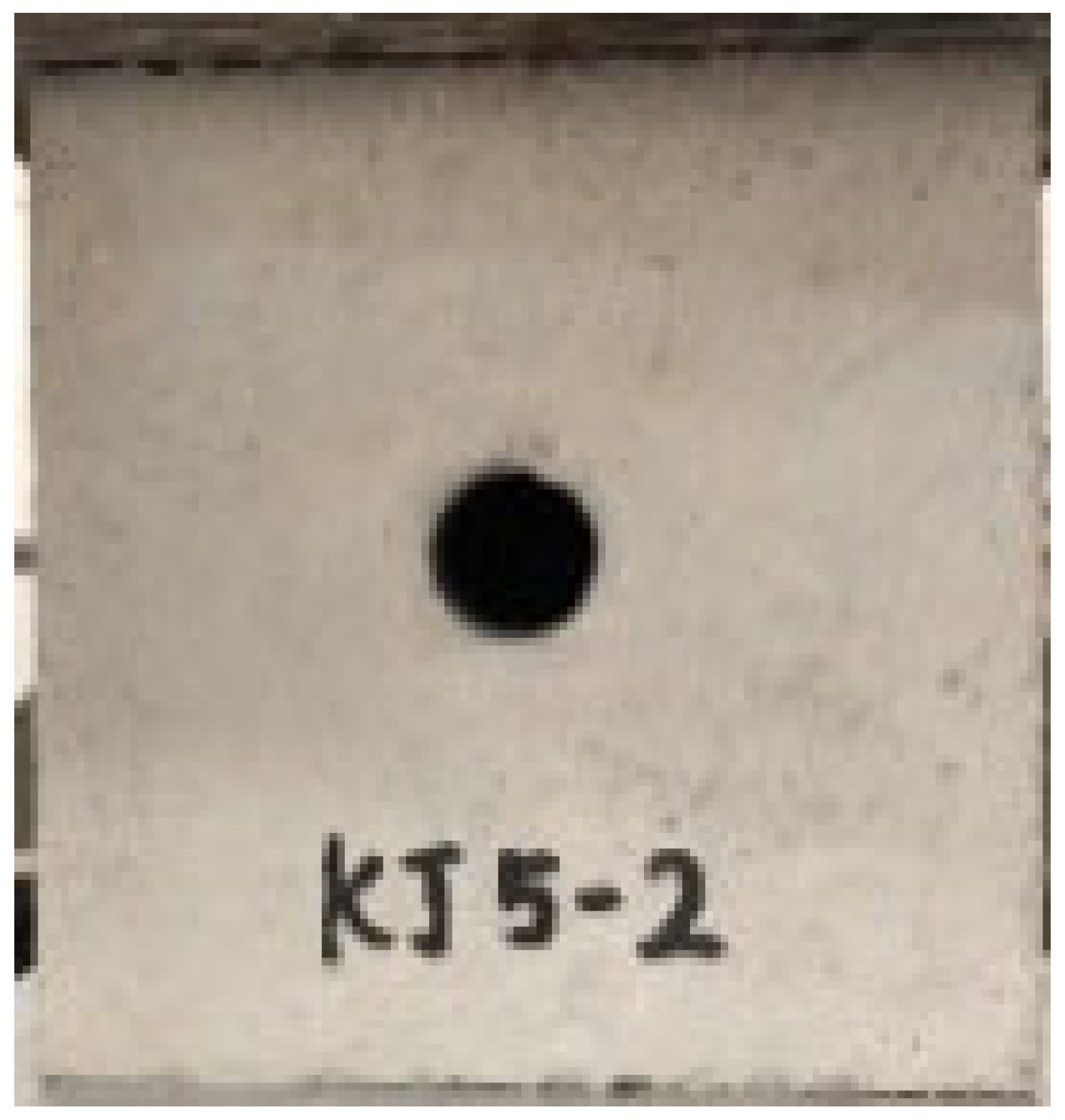
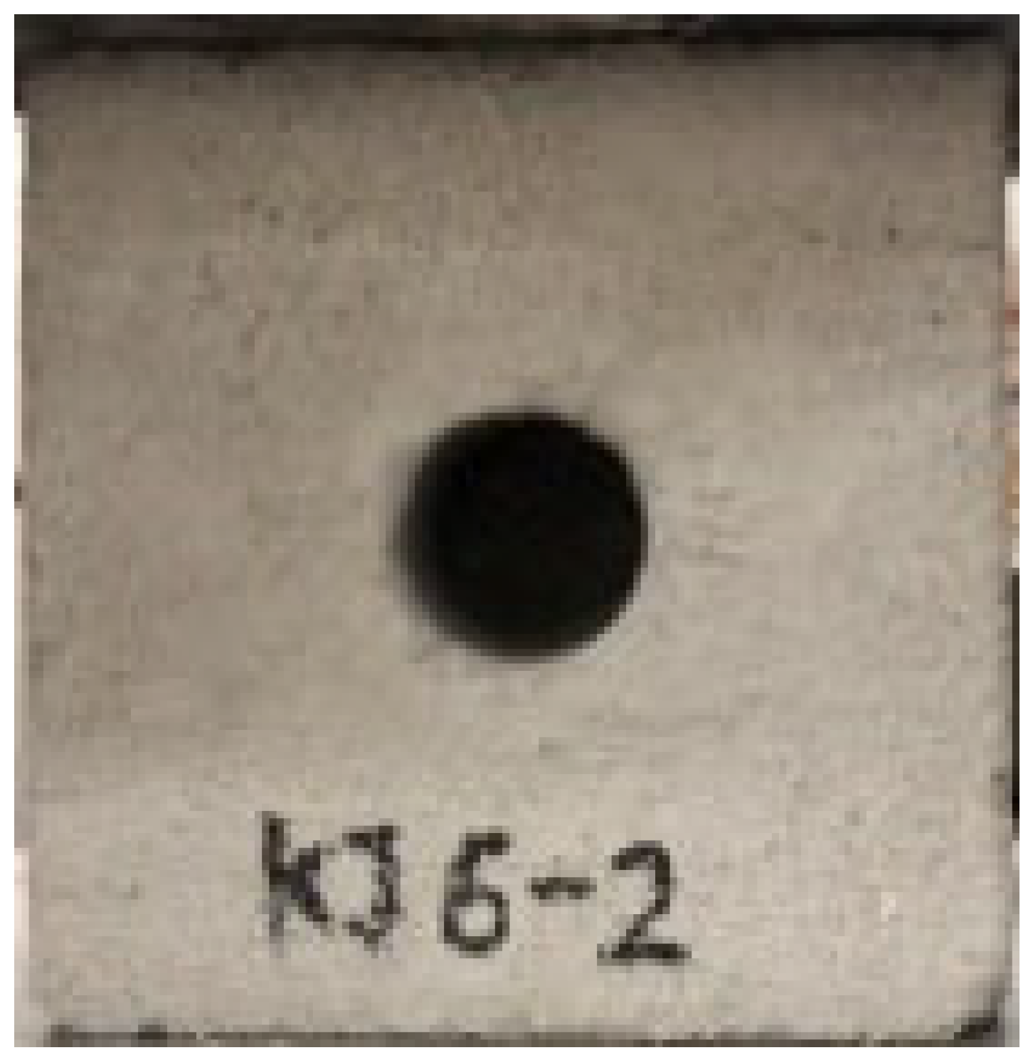
Applsci 13 02511 i001Applsci 13 02511 i002Applsci 13 02511 i003Applsci 13 02511 i004Applsci 13 02511 i005Applsci 13 02511 i006
6 mm10 mm15 mm20 mm25 mm40 mm
2Different drilling depths (drilling diameter of 10 mm)
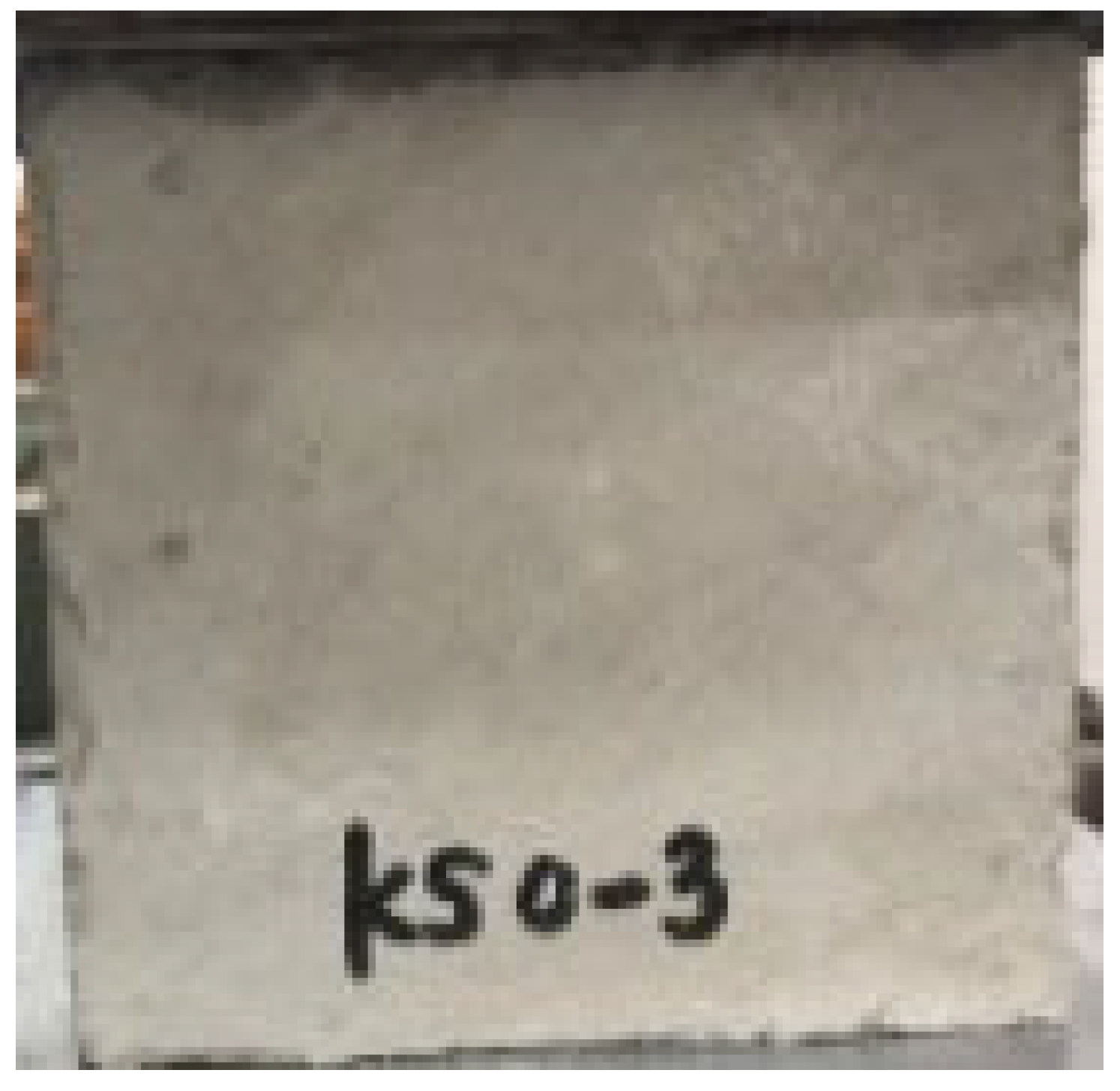
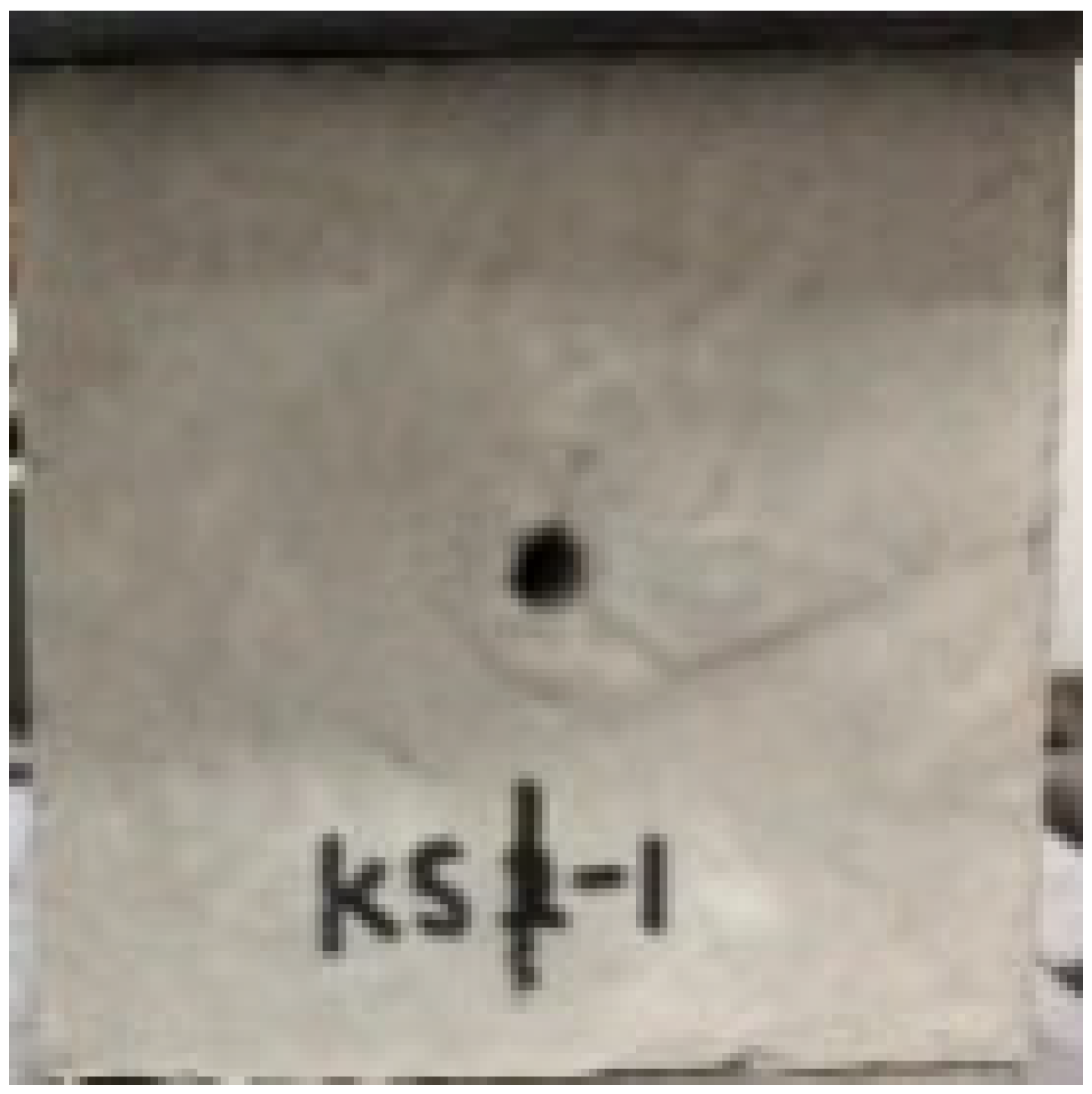
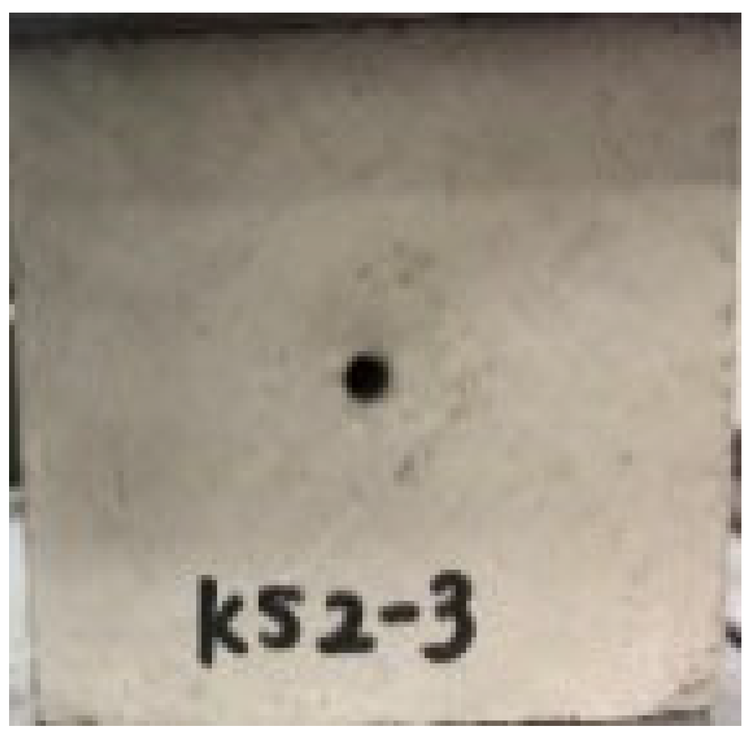
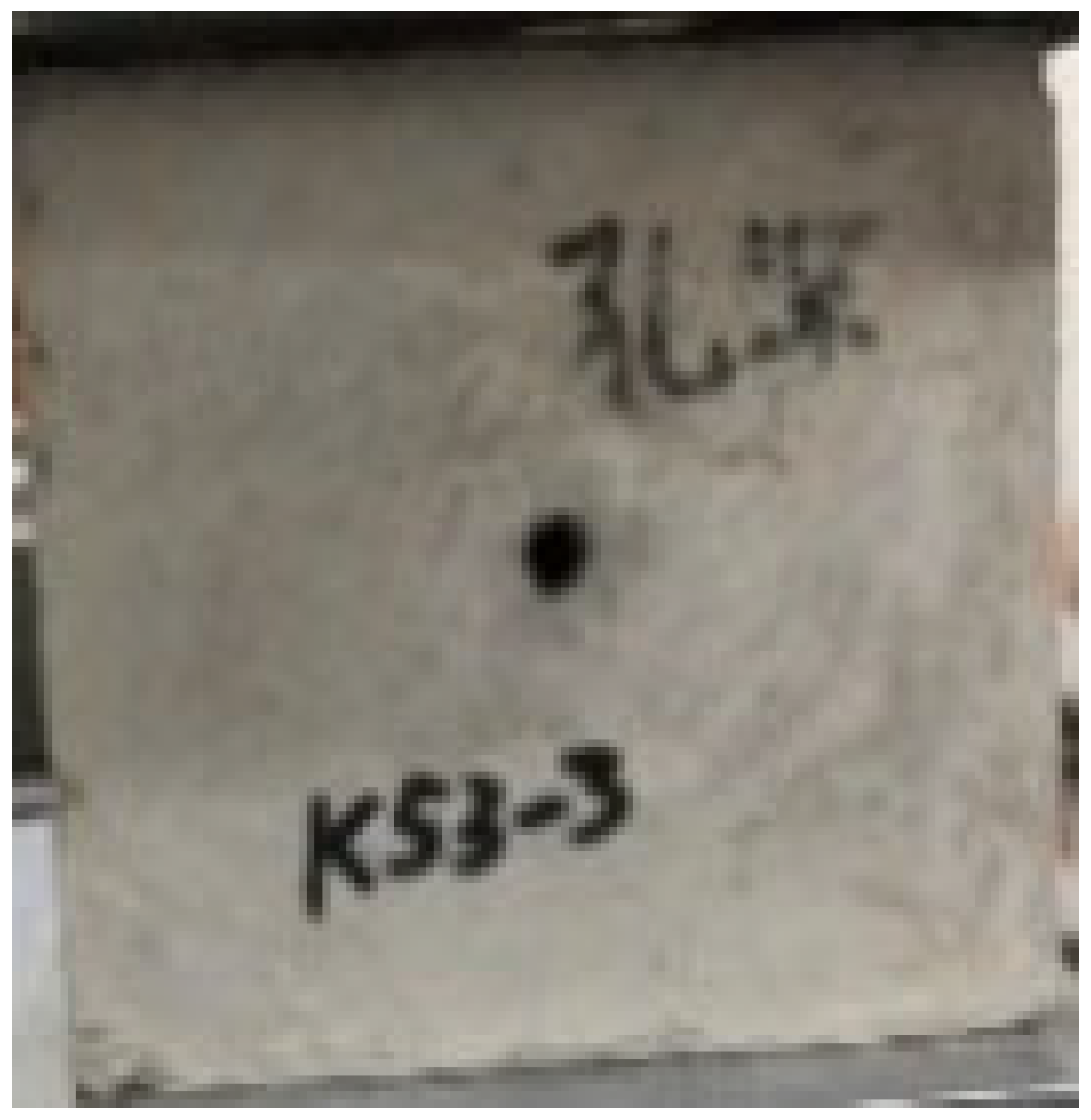
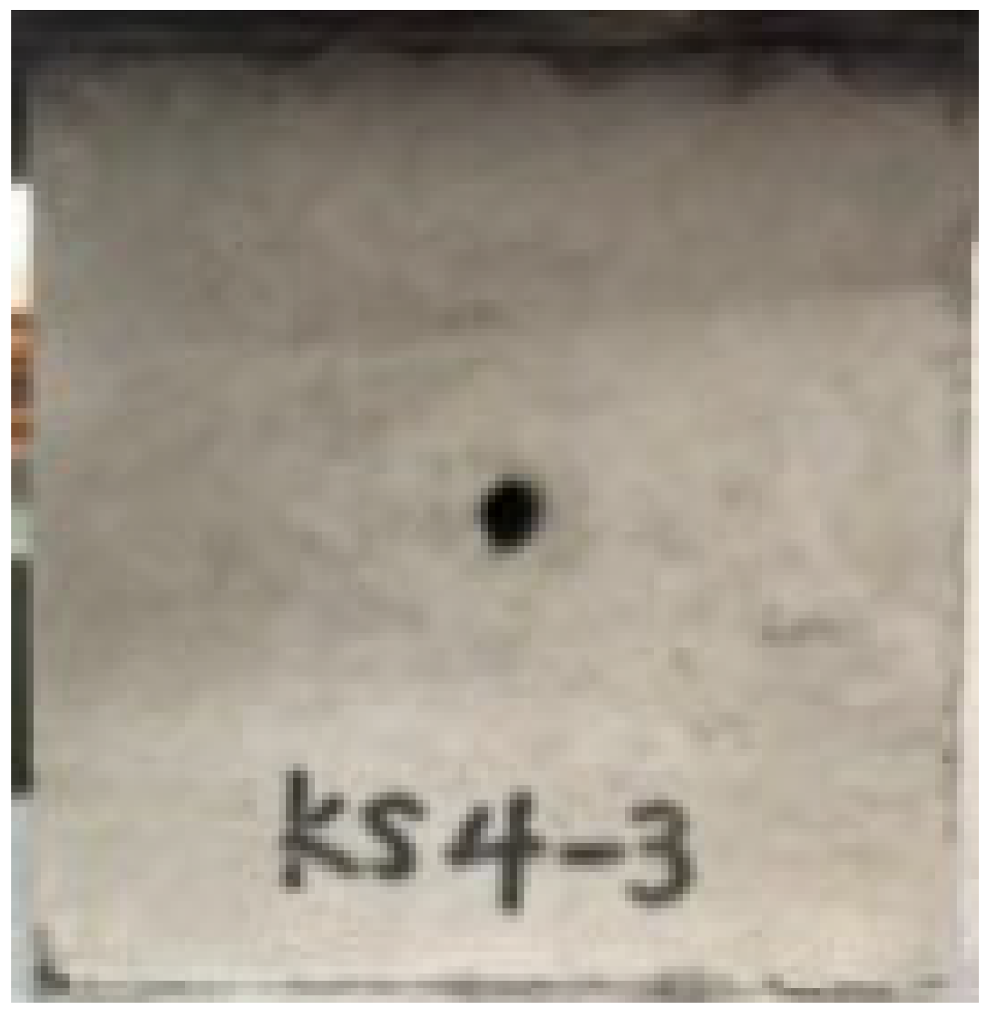
Applsci 13 02511 i007Applsci 13 02511 i008Applsci 13 02511 i009Applsci 13 02511 i010Applsci 13 02511 i011Applsci 13 02511 i012
0 cm3 cm6 cm9 cm12 cm15 cm
3Different drilling spacing (drilling depth of 6 cm and drilling diameter of 10 mm)
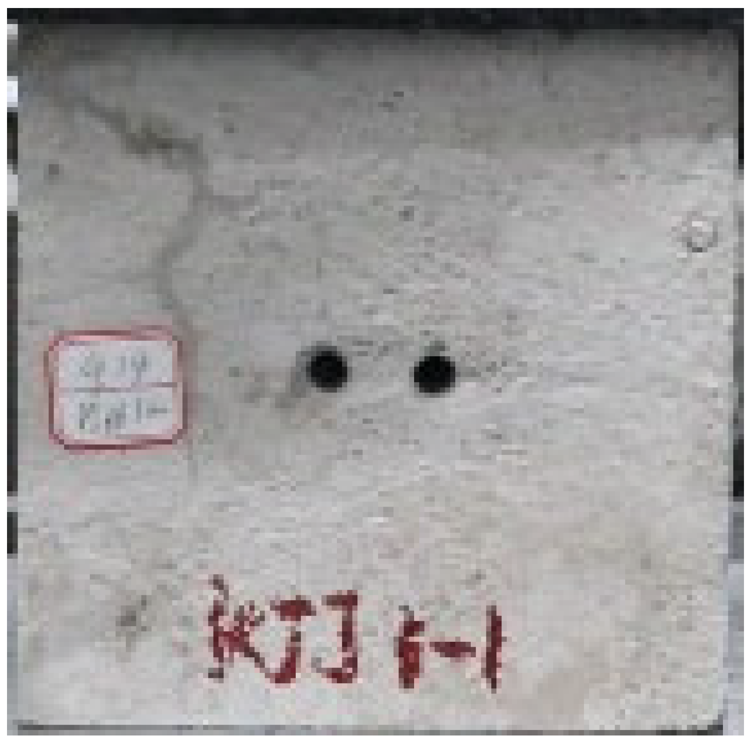
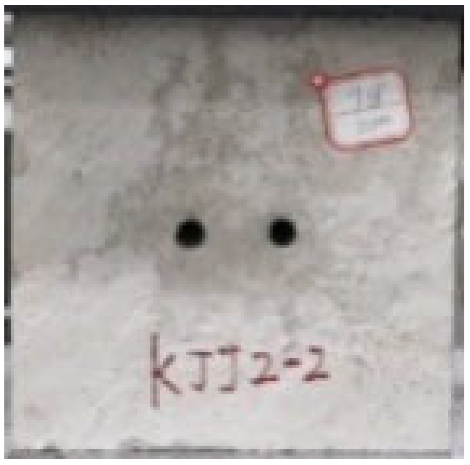
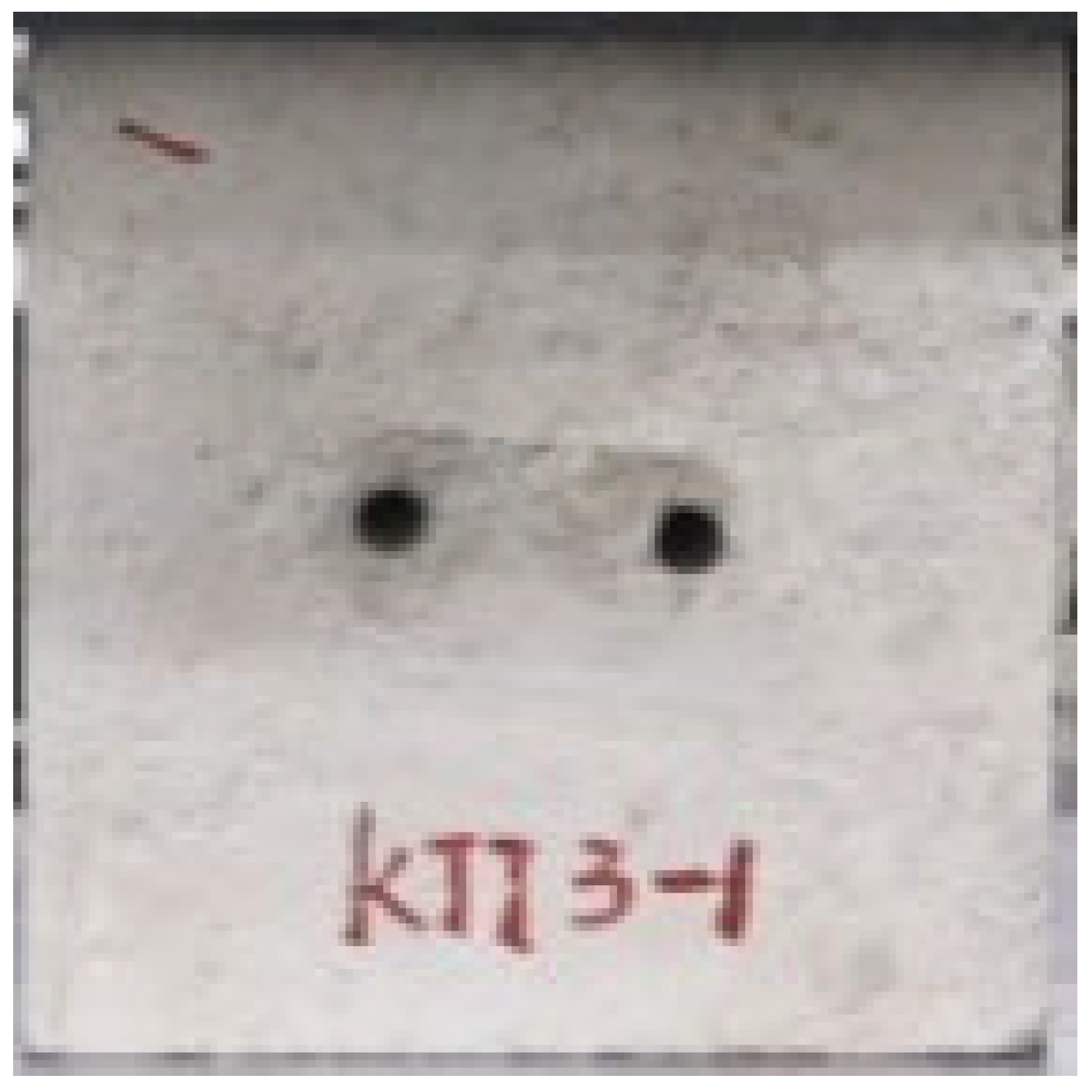
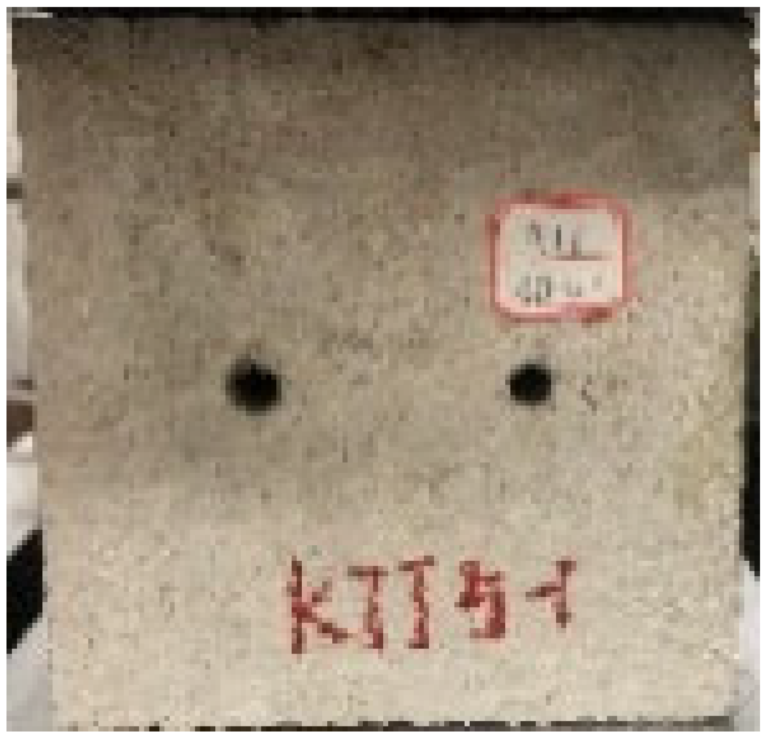
Applsci 13 02511 i013Applsci 13 02511 i014Applsci 13 02511 i015Applsci 13 02511 i016Applsci 13 02511 i017
1 cm2 cm3 cm4 cm5 cm
Table 2. Peak intensity and strain value decrease by percentage at peak intensity.
Borehole Diameter/mmReduction Percentage of Peak Strength/%Percentage Reduction in Strain/%
66.1532.31
106.9036.72
1521.0238.03
2023.7048.44
2525.1049.00
4032.1755.36
Table 3. Peak intensity and strain value decrease by percentage at peak intensity.
Drilling Depth/cmPercent Reduction in Peak Stress/%Percentage Reduction in Strain/%
31.6830.92
66.9042.65
912.3334.03
1211.9332.03
1517.3846.58
Table 4. Peak intensity and strain value decrease by percentage at peak intensity.
Drill-Hole Spacing/cmPercent Reduction in Peak Stress/%Percentage Reduction in Strain/%
140.6426.98
241.2028.84
348.1231.16
449.1332.09
543.6129.77
Table 5. Coal rock mesoscopic parameter table.
NameDensity/(kg·m−3)Elastic Modulus/×103 MPaTensile Strength/MPaAngle of Internal Friction/(°)Poisson RatioCompressive Strength/MPaCohesion/MPa
Coal rock170030.65.64270.2619.2310.5
Table 6. Circumferential stress value along the x-axis and y-axis of the hole edge.
Circumferential Stress Value/MPaValue of r/m
R 3 R 6 R 15R
Along the y-axis σ φ p0−1.042p−0.002p
Along the x-axis σ φ −3p−1.333p−1.125p−1.002p
Disclaimer/Publisher’s Note: The statements, opinions and data contained in all publications are solely those of the individual author(s) and contributor(s) and not of MDPI and/or the editor(s). MDPI and/or the editor(s) disclaim responsibility for any injury to people or property resulting from any ideas, methods, instructions or products referred to in the content.

