Article

An Experimental Study of Industrial Site and Shaft Pillar Mining at Jinggezhuang Coal Mine

1
College of Geoscience and Surveying Engineering, China University of Mining and Technology-Beijing, Beijing 100083, China
2
Key Laboratory of Mine Geological Hazards Mechanism and Control Ministry of Natural Resources, Xi’an 710054, China
3
Research Center of Eco-Geological Environment & Remote Sensing Big Data, Inner Mongolia Research Institute of China University of Mining and Technology-Beijing, Ordos 010300, China
*
Author to whom correspondence should be addressed.
Appl. Sci. 2023, 13(4), 2340; https://doi.org/10.3390/app13042340
Submission received: 22 December 2022 / Revised: 31 January 2023 / Accepted: 8 February 2023 / Published: 11 February 2023
(This article belongs to the Topic Advances on Structural Engineering, 2nd Volume)

Abstract

:
Engineering site and shaft pillars are excavated to prolong the life of collieries and excavate more underground coal. The Jinggezhuang colliery (‘JGZ’) is a resource-exhausted coal mine in eastern China. It was determined that the industrial site and shaft pillar of JGZ would be extracted in 2008. This study excavated an experimental panel to examine the effect of pillar excavation on surface buildings in complicated geological conditions. A new pillar design was proposed based on surface monitoring to increase the recovery ratio. To maintain the safety of the shaft and engineering facilities, panel 0091 was mined and surface deformation was monitored during the experiment. The deformation characteristics and parameters were obtained using a back analysis method. A new pillar was designed using the parameters measured from panel 0091. The design maintained the safety of the shaft but relaxed the restriction of the influence of constructions at the engineering site. The prediction results of the surface subsidence and the deformation of the main building were analyzed. The maximum subsidence of the surface was 7419 mm, but the surface subsidence of the shafts was less than 10 mm. The shafts were weakly influenced by the pillar excavation. The prediction results can be used as basic information for the monitoring and maintenance of buildings in the future. Using the new pillar design, 2.54 million tons of coal resources were mined. This study provides an engineering example and a reference for shaft pillar excavation in the future.

1. Introduction and Geological Conditions
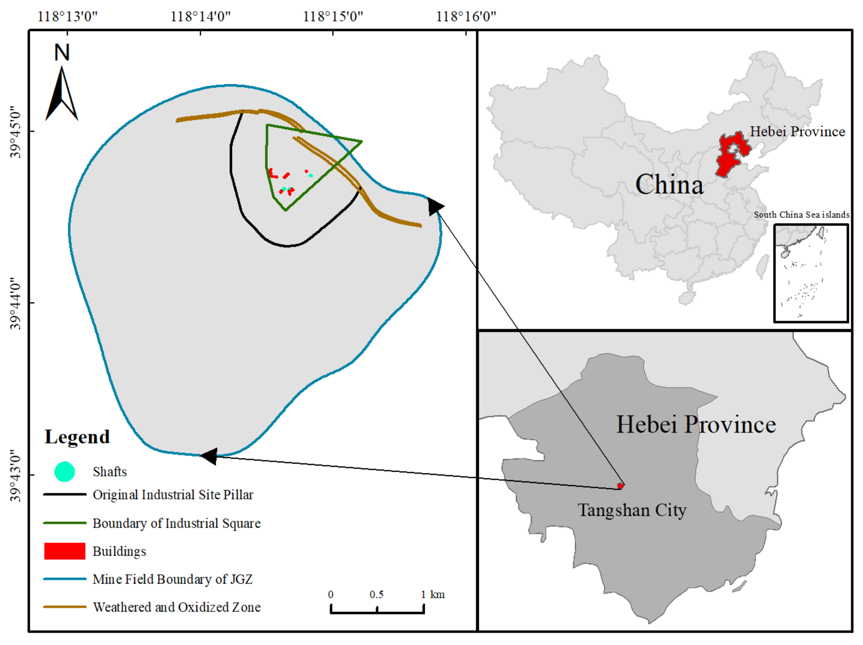
1.1. Introduction

Shaft pillar mining is typically carried out before closing a coal mine. The coal resources available for mining have decreased owing to economic development and an increase in coal mine production. Hence, mines are experiencing the problem of coal resource exhaustion. Numerous collieries excavate shaft pillars to maximize profits before they are closed. There are two main components of shaft pillar mining, i.e., the rock movement theory and technologies for the protection of shafts and facilities. The relationship between shaft and pillar positions has been investigated since the 1960s. Most of the research in this field has focused on technologies such as symmetric extraction, harmonic extraction, and partial caving [1]. In the Akabira Colliery, the shaft was damaged after 2.2 million tons of coal was excavated from the original shaft pillar [2]. Pillar safety is generally evaluated using numerical models. Johnson designed a shaft pillar and stop area and evaluated shaft stability using FEM (Finite Elements Method) simulation [3]. In Poland and Germany, the Knothe theory and Kochmanski’s theory were primarily used to calculate shaft subsidence and deformation [4,5]. Numerical simulation models, such as FlAC3D and FEM, were used to calculate the influence of shaft pillar excavation [6,7,8]. The research on pillar failure shows that remnant pillars typically have a dynamic failure process and brittle shear zones [9,10]. In recent years, surface mining subsidence monitoring technology has developed rapidly. Differential interferometric synthetic aperture radar (DInSAR) technology can obtain surface deformation with pairs of SAR images and has been used widely in mining subsidence monitoring [11,12,13]. The surface deformation and settlement caused by mining can also be obtained using multi-period lidar point cloud registration calculation difference [14]. Those technologies are used widely and played positive roles in the practice. Furthermore, the sensors, such as FBG and strain sensors used in the shaft well deformation monitor [15], provide detailed internal monitoring information. Underground measures are used in most collieries [16], such as partly excavating or using the backfill mining method. A shaft is generally built on a simple geological area and it can be mined at a low cost. Several shaft pillars have been mined successfully, such as the Xinglongzhuang colliery in Yanzhou, Datong colliery in Huainan, and Dahuangshan colliery in Xuzhou. However, there is no technology that can be generalized using in shaft pillar mining. In situ measurement-based methods are important for preventing damage to shafts [17]. Shaft pillars are generally built under industrial construction sites such as shafts, hoist houses, coal wash plants, and office buildings. These buildings should be protected when underground pillars are mined out. A shaft is a strategic passage for an underground coal mine. Thus, a shaft pillar is typically mined immediately before a colliery is closed and it should be investigated for safety before being mined. A large amount of coal mine resources have been exhausted owing to economic development and large energy consumption. This study has developed a method based on experiments to excavate resources in complicated surface and underground conditions. The proposed method is based on actual geological conditions and prioritizes safety. It provides an example for industrial square and shaft pillar mining.
Fulfilling the aims of this study was expected to find a balance between coal resource mining and building protection and try to improve the recovery rate while reducing the loss of shaft and building. A new pillar was designed for the shaft based on the surface monitored data. It can reduce the coal pillar under the shaft and extend the production life of the mine as much as possible. In particular, this paper contains two parts research contents. First, the precise leveling data and parameter inversion for the Probability Integral Method (PIM). Second, the prediction and evaluation for the shaft and important buildings affected. The purpose of this study was to extract the coal resource as much as possible under the condition of ensuring the shafts and buildings safety.

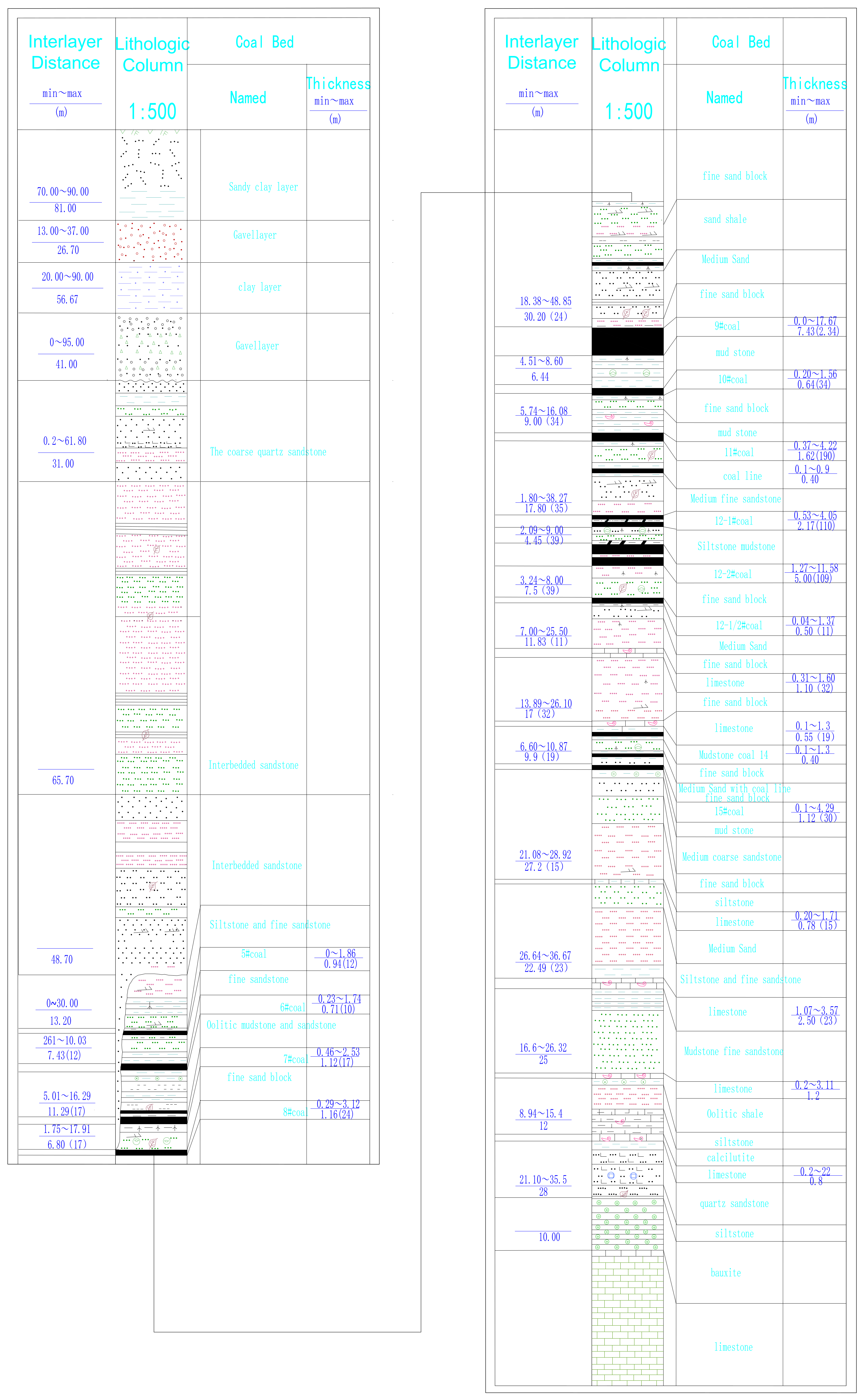
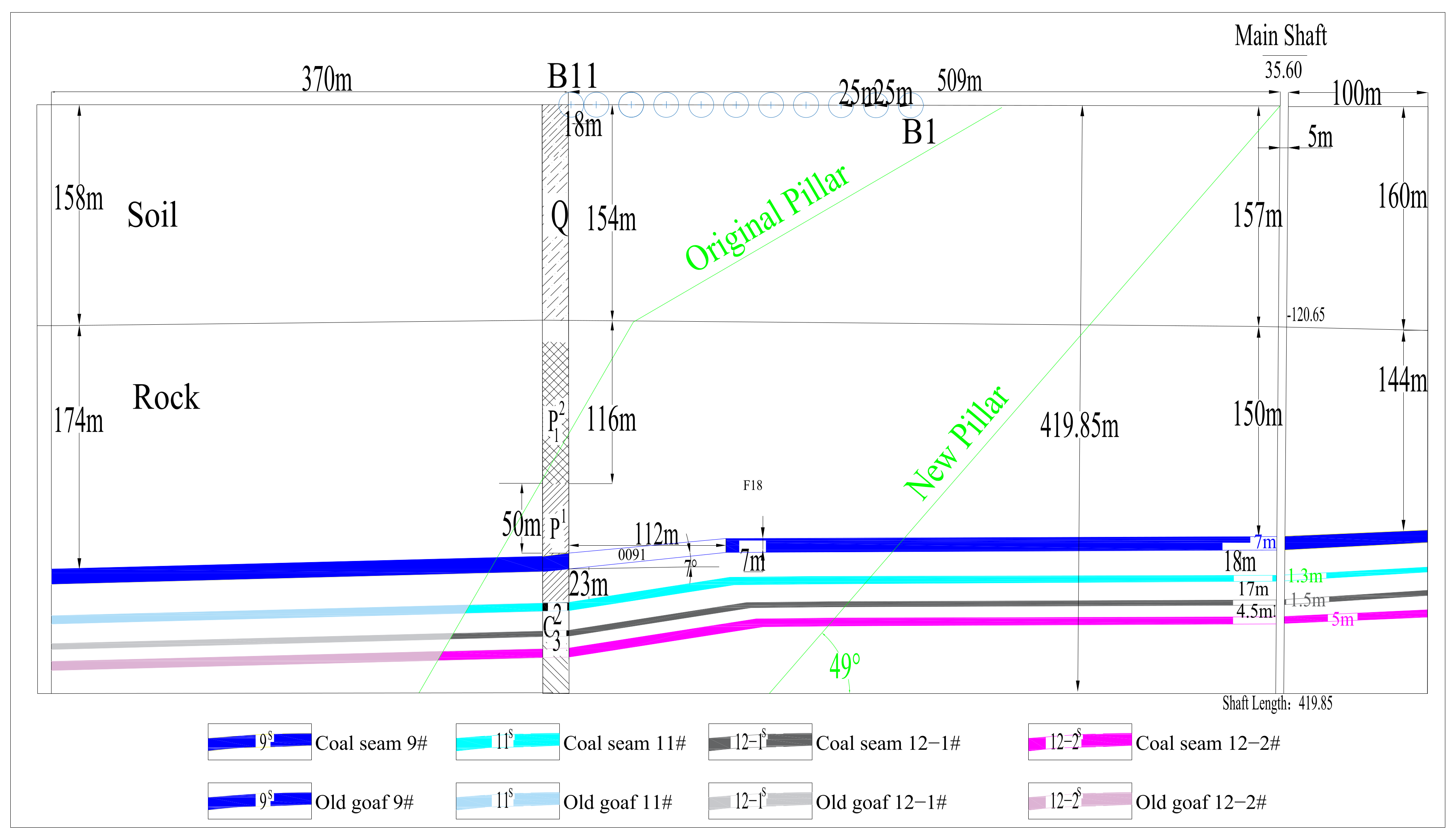
1.2. Geological and Mining Conditions

The Jinggezhuang colliery (JGZ) is located in Tangshan, Hebei Province, East China; the location of JGZ is shown in Figure 1. Mining was started at JGZ in 1979 and the annual production is 1.2 million tons. JGZ is located in a soil deposit plain land. The field is flat, with an elevation of +38.8 m in the north and +23.85 m in the south. The average elevation is 35.6 m.
Mining was carried out at JGZ for 38 years and negligible coal resources remained. JGZ was closed in 2017. It was determined that the industrial site and shaft pillar at JGZ would be mined to excavate all coal resources. There are four coal seams in this pillar: 9#, 11#, 12-1#, and 12-2# with thicknesses of 7 m, 1.3 m, 1.5 m, and 5 m, respectively. The distances from 9# to 11#, 11# to 12-1#, and 12-1# to 12-2# are 18 m, 17 m, and 4.5 m, respectively. The coal seam angles are 4°∼8° and 15°∼25° above and below an elevation of −260 m, respectively.
The thickness of quaternary alluvium in this region is approximately 165 m. The stratigraphic classification of the entire region is weak and medium hard and a brief borehole histogram was outlined in the Appendix A in Figure A1. It can be seen from the attached figure that the overlying strata are mainly composed of fine sandstone, siltstone, medium sandstone, and their interbedding. In order to better explain the geological conditions of the study area, the author provided a borehole histogram and put it in the Appendix. It can be seen from the attached figure that the overlying strata are mainly composed of fine sandstone, siltstone, medium sandstone, and their interbedding. At the beginning of the construction of JGZ, an industrial square protective coal pillar was designed, which played a great role in ensuring the safety of mine production. However, with the depletion of resources, continuing to retain the coal pillar in the original design will waste a lot of coal resources. The managers hope to extract as much coal resources as possible while ensuring the safety of the shaft. A new shaft pillar area is needed. Since 2008, JGZ has faced difficulties in terms of coal production and cost owing to the exhaustion of coal resources. To improve the plan of the subsequent production, panel 0091 was mined with surface deformation monitoring as an experiment to study the surface deformation characteristics and mine prediction parameters using the probability integral method (PIM). Furthermore, provide new parameters for the new shaft pillar design.

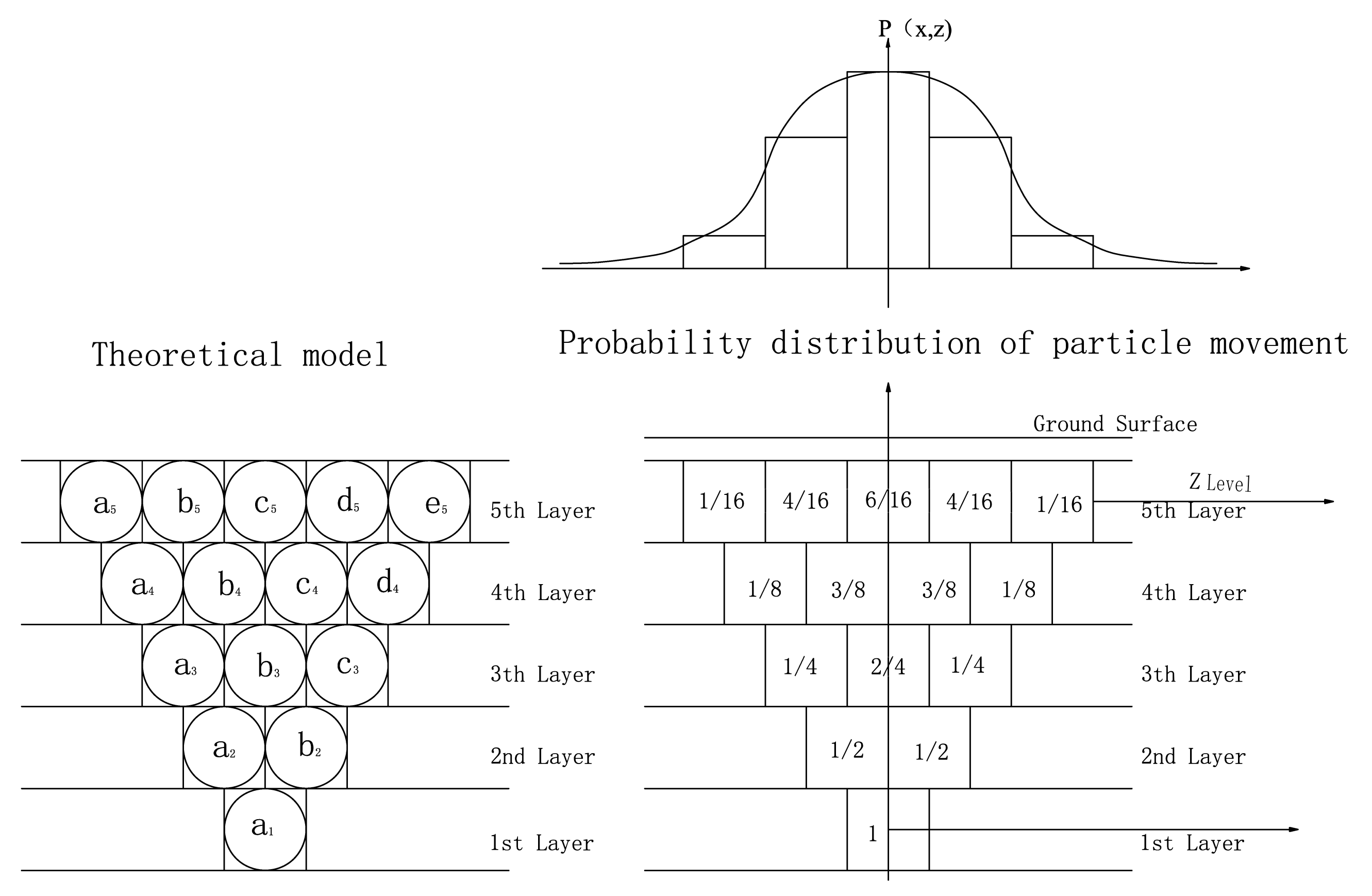
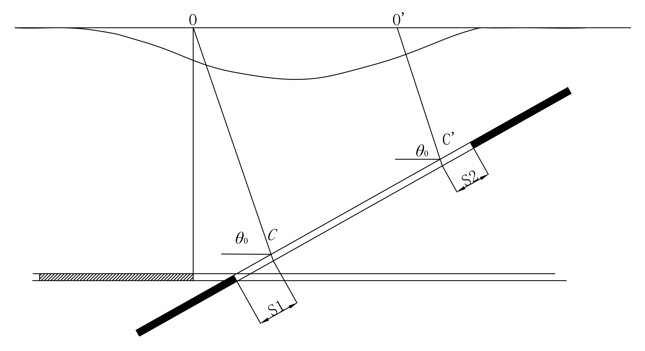
2. Probability Integral Method Based on Stochastic Model

The PIM (also referred to as the geometry integral method) is a mine prediction function based on the stochastic medium model [18]. It was first used in China by Baochen Liu and Guohua Liao [1] in the 1960s. This method requires only eight parameters based on site surveys and it provides reliable deformation results. In addition, the method is widely used by engineers and technical personnel. The method is mostly used in China and it is a government-recommended method for mine subsidence and damage prediction [19].
In this method, it is assumed that a rock is formed with a small stochastic element, as shown in Figure 2, and that deformation (or subsidence) can be calculated based on the deformation of small elements. It is believed that the mining surface subsidence is caused by the relative movement of the particle model as shown in Figure 2. The particles completely lose contact with each other and can move relatively. When the small particles below are removed, a small cell of the adjacent cell of the upper layer will fall into the removed cell grid due to gravity. According to this stochastic process, the probability curve of surface movement P(x, y) similar to the bell function can be derived. To obtain the surface movement curve after a large number of unit bodies have been removed, only use integration with P(x, y). The subsidence of a small-element mining can be calculated using Equation (1) [1]. The deformation for underground mining can be obtained using Equations (2)–(6) [20].
W e ( x ) = 1 r e π x 2 r 2
W ( x , y ) = j = 1 n D j W 0 W e ( x , y ) d s d t = j = 1 n D j W 0 r j 2 e π ( x s ) 2 + ( y t ) 2 r j 2 d s d t
i ( x , y , φ ) = W ( x , y ) x cos φ + W ( x , y ) y sin φ = j = 1 n D j 2 π W 0 r j 4 { [ ( x s ) cos φ + ( y t ) sin φ ] e π ( x s ) 2 + ( y t ) 2 r j 2 } d s d t
K ( x , y , φ ) = i ( x , y , φ ) x cos φ + i ( x , y , φ ) y sin φ = j = 1 n D j 2 π W 0 r j 4 { 1 2 π r j 2 [ ( x s ) cos φ + ( y t ) sin φ ] 2 } e π ( x s ) 2 + ( y t ) 2 r j 2 d s d t
U ( x , y , φ ) = j = 1 n D j 2 π b W 0 r j 3 { [ ( x s ) cos φ + ( y t ) sin φ ] e π ( x s ) 2 + ( y t ) 2 r j 2 } d s d t
ε ( x , y , φ ) = j = 1 n D j 2 π b W 0 r j 3 { 1 2 π r j 2 [ ( x s ) cos φ + ( y t ) sin φ ] 2 } e π ( x s ) 2 + ( y t ) 2 r j 2 d s d t
where (x,y) are the coordinates of a surface point; φ is the direction angle of surface movement; W0 is the maximum ground subsidence, provided by W0 = mqcosα; We(x,y) is the subsidence of a small element mining; r is the major influence radius, which is provided by r = H/tanβ; H is the mining depth; q is the subsidence factor; b is the displacement factor; m is the mining thickness; tanβ is the tangent of the major influence angle; D is the calculated mining area, which is obtained by subtracting the deviation of an inflection point (S) from the actual mining area; n is the number of mining panels; and α is the dip angle of the coal seam.
For an inclined coal seam, as shown in Figure 3 [20], the inflection point of a subsidence curve is not located directly above the boundary of the goaf but at the dip-side point, O. The angle between OC and the horizontal line is another probability integration parameter, θ0, which is referred to as the propagation angle of extraction. S is a parameter of the inflection point. It is the distance between the overhanging roof and goaf boundary. The inflection point shifts because of the overhanging roof.
Therefore, the parameters of the PIM are q, b, tanβ, θ0, and S, where S is different in the dip (S1), rise (S2), and strike (S3) directions. These seven parameters are required for predicting mining subsidence and they can be calculated from the surface subsidence observations acquired from neighboring stations.
Subsidence, tilt, curvature, horizontal displacement, and strain are denoted as W, i, K, U, and ε, respectively.
The PIM method is a semi-empirical physical model. The parameters can be obtained from site survey data and, thus, reliable subsidence can be calculated. There are a lot optimized inversion algorithms that can be used to calculate the PIM parameters, such as the Gauss–Newton method, Macquard method, Modulus vector method, genetic algorithm (GA) method, and swarm algorithm. In this paper, we used the GA method to invert the PIM parameters. GA is a computational model of biological evolution process simulating natural selection and genetic mechanism of Darwin’s biological evolution theory. It is a method of searching the optimal solution by simulating natural evolution process. It used widely in parameter inversion. The detailed calculation process of GA inversion of the PIM method can be found in papers [21,22].

3. Mining Experiment of Panel 0091 and Subsidence Monitoring
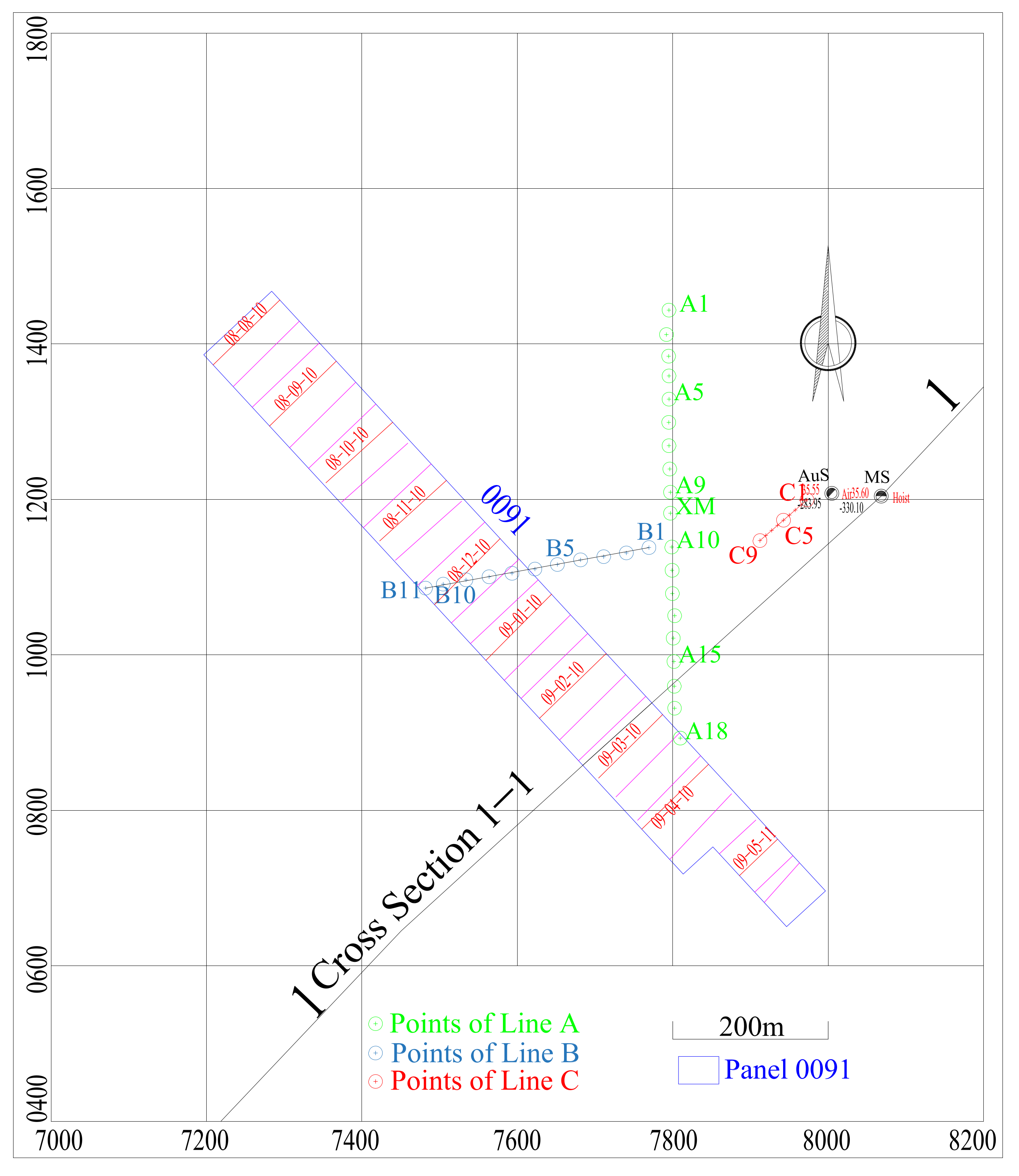
3.1. Introduction

Panel 0091 was mined as an experiment to mine the shaft pillar and maintain the safety of the buildings in the industrial area. In addition, the site deformation was monitored to obtain the surface movement law of the investigated area. Panel 0091 is located on the southern boundary of the industrial and shaft pillars. Around the panel are the goafs of the 1970s and 1980s. The average floor elevation and surface elevation of the panel are −295 m and +35.5 m, respectively. The average mine thickness is 6.9 m. The coal seam angle is 3°∼12°, with an average of 7°. The strike length and tendency length were 1050 m and 116 m, respectively. The panel was mined from 1 August 2008 to 30 April 2010. Three site survey lines were set in June 2008. The survey started in September 2008 and ended in May 2010 and it was carried out 29 times. The schematic of the panel and survey lines is shown in Figure 4. Line A consisted of 19 points (A1–A18 and XM). All site points were set along a road. The interval between consecutive points was 30 m.
Line B consisted of 11 points (B1–B11). It was located in the western part of the industrial area. The distance between consecutive points was 30 m.
Line C consisted of 9 points (C1–C9). It was located close to the hoist house of the auxiliary shaft and used to obtain the deformation of the hoist house. The interval between consecutive points was 10 m.
S3 leveling was used in the survey with fourth-order leveling (mean square error per kilometer <5 mm). All the results were consistent with mine surveying regulations [23].

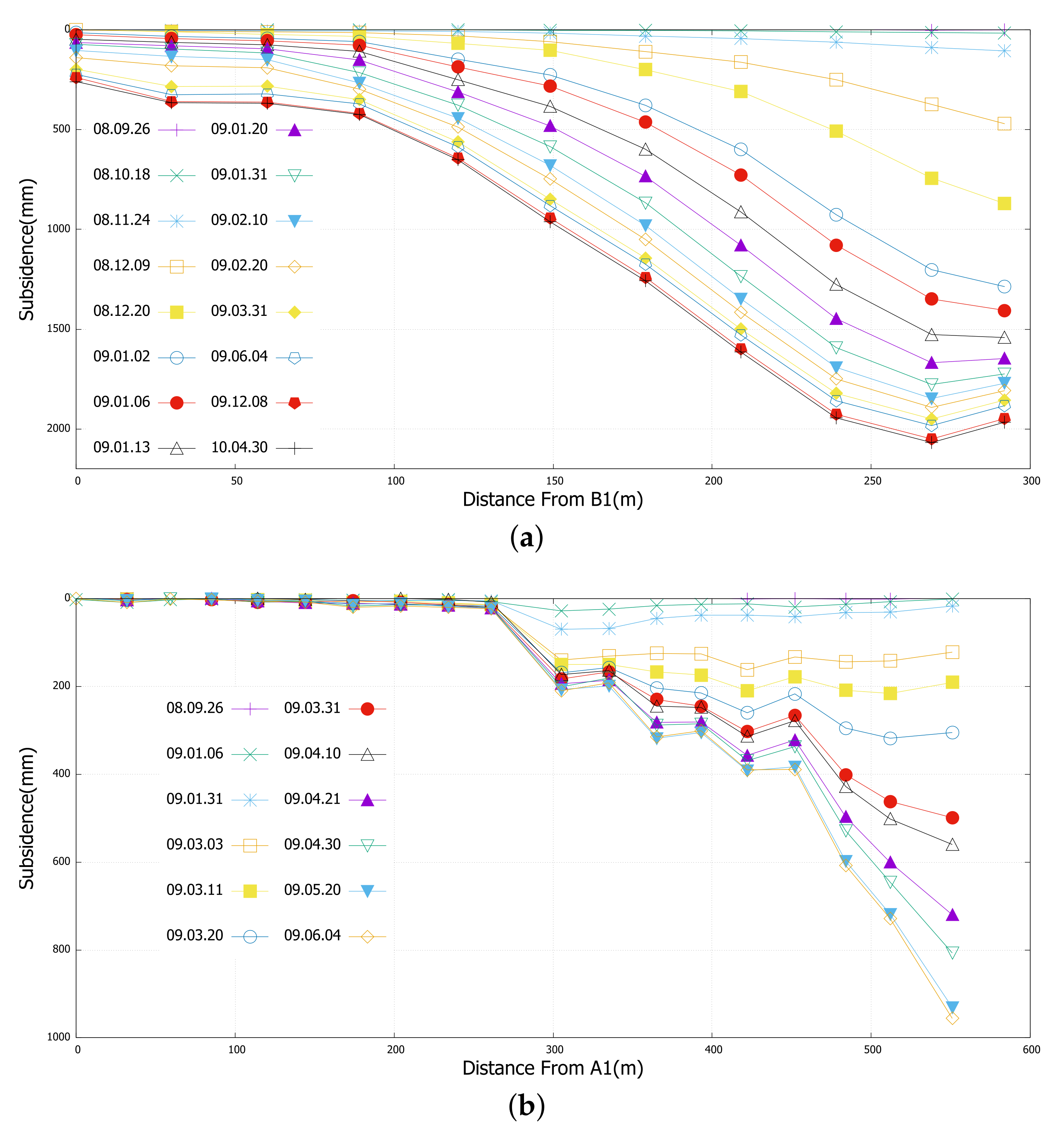
3.2. Measured Subsidence

The subsidence of lines A and B are shown in Figure 5. The following parameters can be obtained through data analysis:
(1)
Subsidence boundary angle: As defined in the regulation [19], the subsidence of point C6 is 10 mm and this can be considered as the subsidence boundary. The distance between C6 and the panel boundary is 274 m. The mine depth is 318 m. The subsidence boundary angle of the rise face is 49°.
(2)
Maximum subsidence angle: B10 represents the maximum measured subsidence. The distance between B10 and the panel center is 33.7 m and the mine depth of the center is 333 m. Thus, the maximum subsidence angle is 84°.
(3)
Advance angle: According to the data of B9, the inital influenced distance is 189 m. Thus, the advance angle is 61°.
(4)
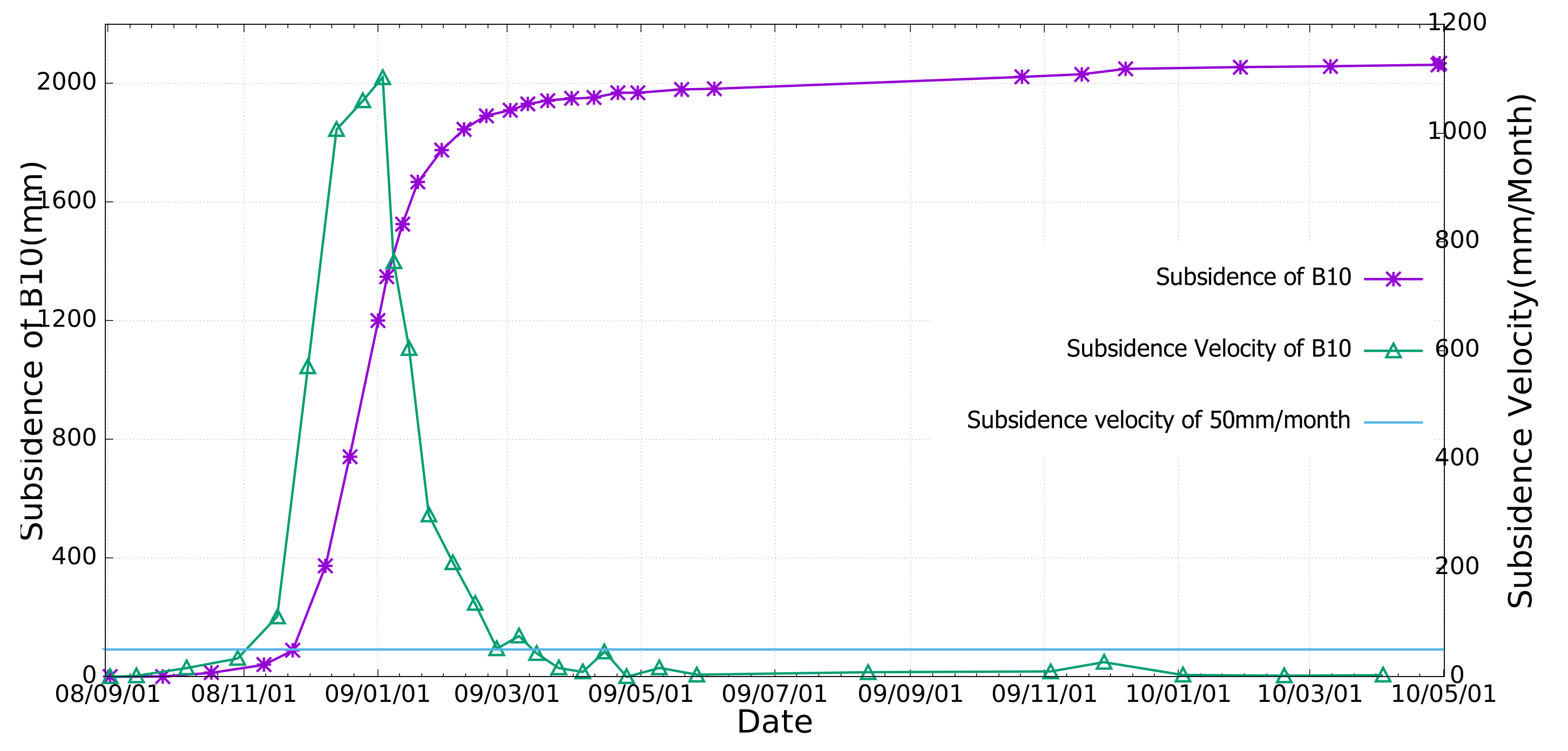
The subsidence of B10 is used to study the dynamic subsidence laws. As shown in Figure 6, the maximum subsidence velocity is 1059 mm/month. The velocity is more than 50 mm/month for 124 days.

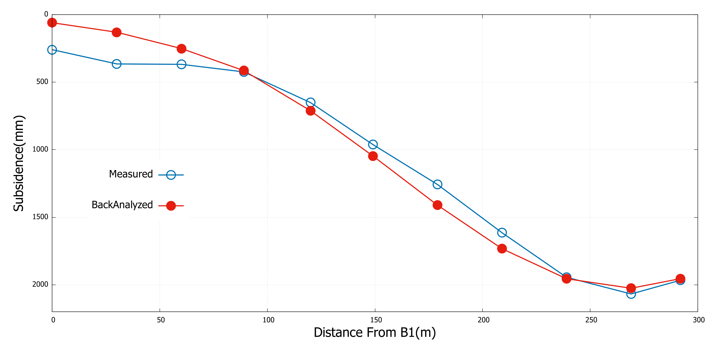
4. Pim Parameter Back Analysis Based on Line B Data

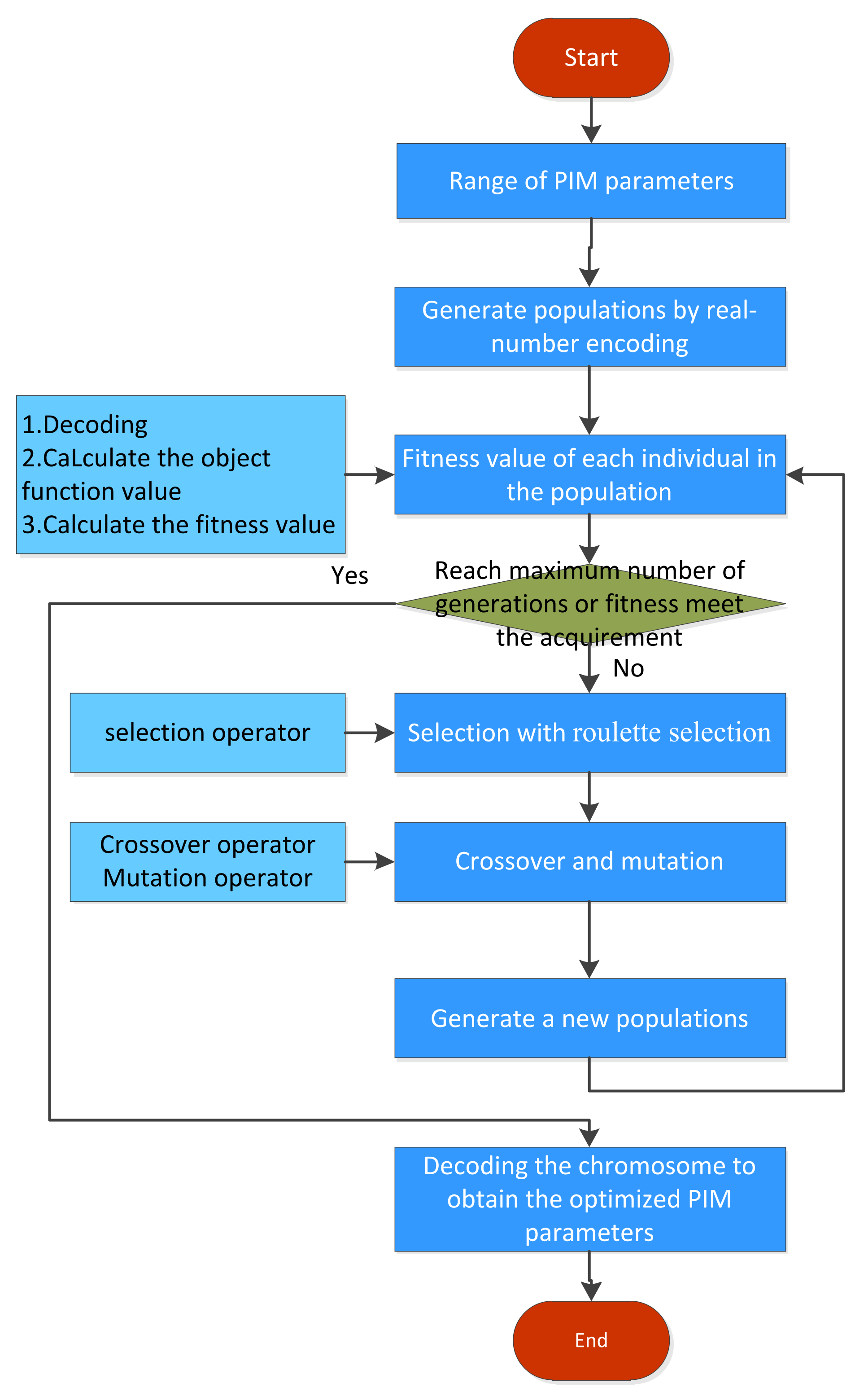
4.1. Ga Method of PIM Parameter Back Analysis

It is necessary to obtain reliable mining subsidence parameters to predict the shaft pillar mining subsidence. A GA method is used for PIM parameter back analysis [24,25]. This method uses a GA and the minimum mean square error criterion based on the subsidence inversion to obtain the PIM parameters. The main process flow is shown in Figure 7 [24].
The GA method with its crossover, mutation mechanism, and global optimization superiority can invert the PIM parameters and obtain reliable results.

4.2. Results

The back analysis results obtained using the inversion model are
q = 0.88
tanβ = 1.61
θ0 = 85°
S/H = 0.05.
The plot of the back analysis results versus the measured data is shown in Figure 8. The back analysis results are in agreement with the measured subsidence. Therefore, the parameters can be used for predicting the shaft pillar mining subsidence in the future.

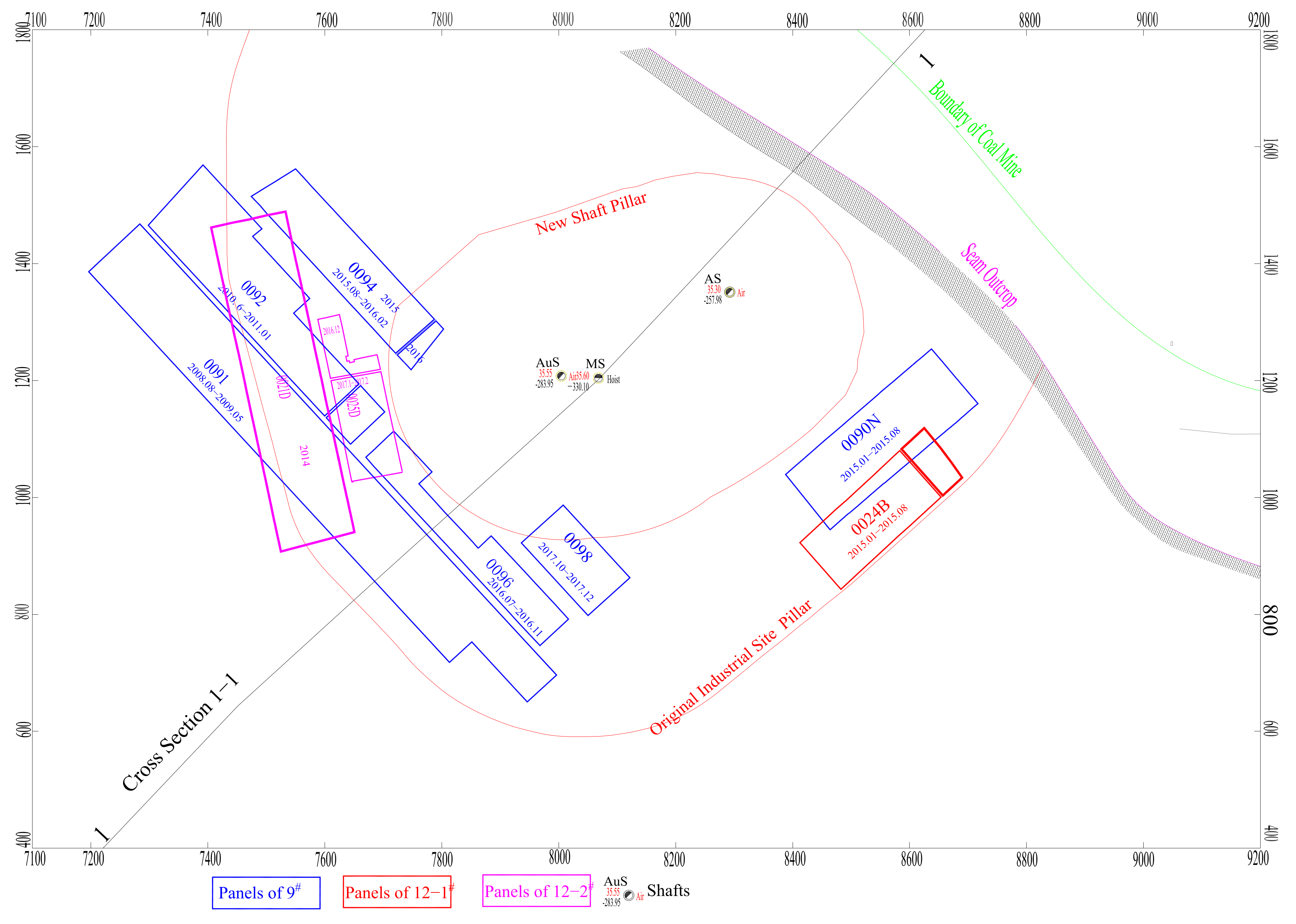
5. New Shaft Pillar and Panel Design

Shaft pillar mining is an integrated technology for unconventional underground coal mines. A shaft pillar influences the buildings constructed on the surface, such as head frames, shafts and their facilities, shaft stations, and tunnels. It is a 3D space protection system. The research and design of shaft pillars has two purposes. The first is to minimize the influence of shaft pillars on surface buildings. The second is to ensure the safety of production facilities.
According to the excavation and monitoring results obtained for panel 0091, a new shaft pillar was designed to improve the recovery ratio. The new design was based on two rules. The first was that the required protection level of the buildings in the industrial square should be reduced.
The second was to ensure the safety of the shaft until the colliery was closed.
A new shaft pillar was designed with a boundary angle of = 49° obtained from panel 0091, as shown in Figure 9.
The panels were designed for production until the coal mine was closed in December 2017. The schematic of the new panels is shown in Figure 10 and their parameters are provided in Table 1.

6. Prediction of Ground Movement

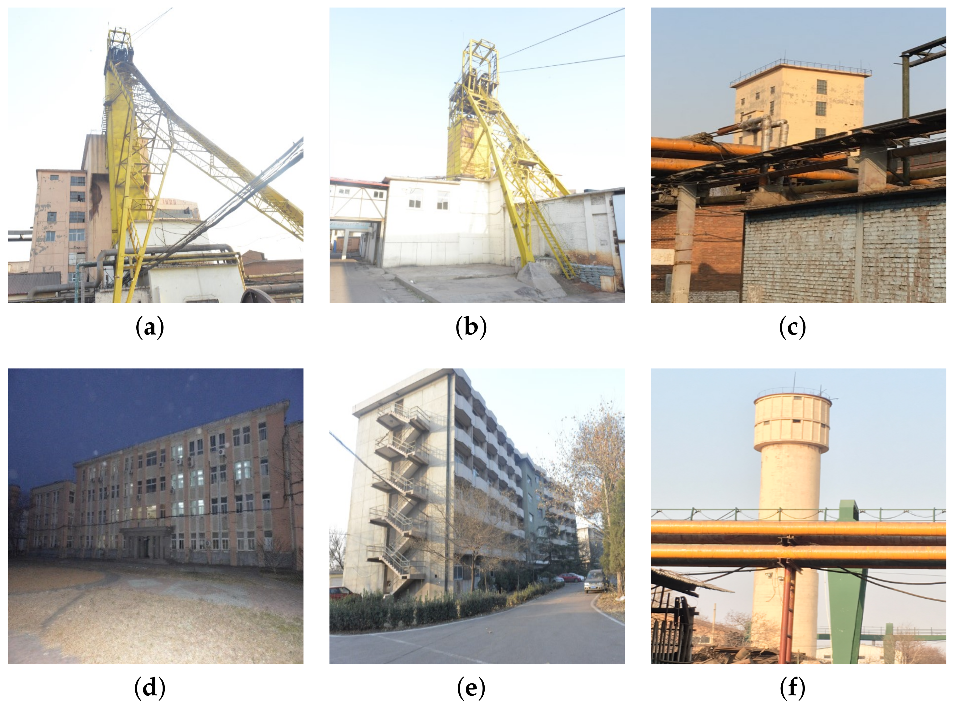
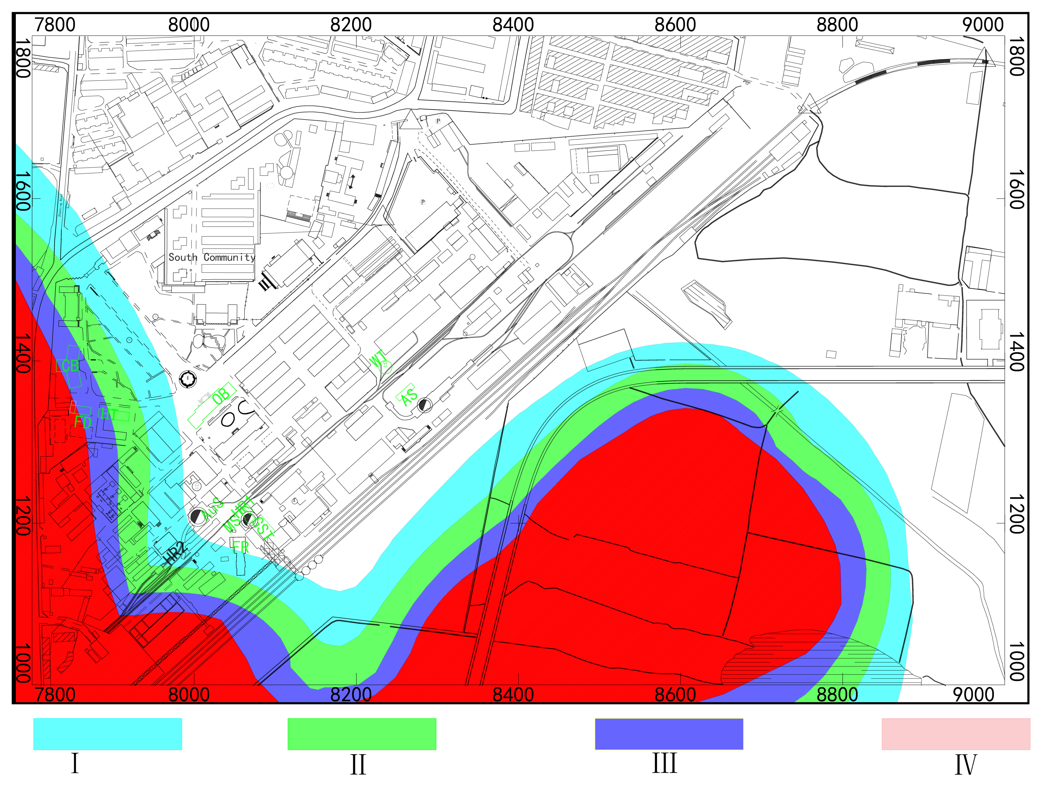
6.1. Displacement of the Ground

Building maintenance data are required to maintain the safety of buildings and prevent damage to buildings. The mine subsidence was predicted using the parameters obtained for panel 0091 and displacement factor b = 0.3. The ground movement was predicted using the PIM model. The results are shown in Figure 11 and the maximum deformation values are shown in Table 2.

6.2. Subsidence and Deformation of Surface Buildings

The new design considered the safety of the shaft. However, the surface buildings were damaged because of excavation. Therefore, it was necessary to predict the deformation of the surface buildings. There are several buildings in the industrial square (the images of a few buildings are shown in Figure 12) and a few of them are deformation sensitive. These buildings are key production facilities and should be repaired regularly if they are damaged owing to ground deformation. The positions of these buildings are shown in Figure 13. In order to evaluate the impact of mining on buildings, we adopt the evaluation standard provided by the Coal Industry Bureau of China (CIB), which is a deformation damage evaluation index based on the statistical summary of China’s masonry structures. It provides a reference basis for evaluating the damage of surface buildings caused by mining subsidence. The reference criterion is provided in Table 3. As the index shown in Table 3, building damage is divided into four levels according to surface deformation, inclination, and curvature. Among which, rank I and II are the small deformation influence level and III, IV grades are the serious ones.
A predicted damage partition map can be obtained using the deformation criterion of brick-masonry buildings, as shown in Figure 13. The deformation parameters for various buildings are provided in Table 4. As predicted, the pillar excavation has caused level IV damage to a few buildings and these buildings must be repaired or demolished for safety. However, the pillar with the new design has a negligible influence on the shafts. The main shaft, auxiliary shaft, and air shaft are located outside of the mining subsidence influence area of the shaft pillar mining.
As shown by the results in Figure 11 and Figure 13 and Table 4, some of the buildings and facilities will be damaged by the surface deformation. However, the office building (OB), main shaft (MS), auxiliary shaft (Aus), air shaft (AS), and water tower (WT) are outside the scope of influence. Those important buildings or facilities can ensure that the production of the coal mine is not affected. The influenced buildings are listed in Table 4 and these can be used as the design accordance for maintenance. However, other buildings at the engineering site should also be considered in the maintenance plan.

7. Discussion

Energy consumption has increased significantly owing to rapid economic development in the last thirty years. The annual coal production in China is approximately 3.68 billion tons [26]. This has caused coal resource exhaustion in numerous collieries in East China. A few collieries must face bankruptcy and be closed. For most collieries, the engineering site and shaft area pillars are the only remaining coal resources. The excavation of these pillars can not only provide economic benefits and prolong the life of collieries but also reduce the wastage of coal resources. The following three aspects should be considered for pillar excavation:
1.
The most important aspect is that excavation should not be carried out before a shaft is closed. In addition, mechanical analysis may be required in a few cases.
2.
Mine subsidence should be predicted to determine the influence of surface subsidence on engineering facilities and buildings.
3.
For deformation sensitive facilities, deformation monitoring and warning are the best methods of preventing loss of life and economic damage. This study used the PIM for predicting mine subsidence. The parameters obtained from the field-measured data were reliable and robust. However, as it is based on the discrete medium theory, it is difficult to calculate the stress and strain inside the rock. Therefore, if shafts are influenced by pillar mining, further analysis based on mechanical simulation is necessary. The major challenge is to balance economic benefits and safety.
Until the closure of the colliery in December 2017, 2.54 million tons of coal resources were extracted from the mining of pillar 0091 in 2008. This provided not only economic benefits but also sufficient time to resettle industrial workers in an orderly manner.

8. Conclusions

Surface buildings can be damaged by the deformation caused by mining subsidence. Underground pillars are used to prevent this damage. However, engineering site and shaft pillars are the only remaining coal resources for a colliery before it closes. As shafts are crucial passageways in coal mines, it is difficult to maintain a balance between coal production and safety. The results of this study demonstrate the following key points for shaft pillar mining:
(1)
First, a mine experiment with a deformation monitor is required. The mining subsidence geometry characteristics and prediction parameters can be obtained from experimental data analysis.
(2)
A new pillar should be designed on the basis of the parameters of the research area. The pillar should ensure that the safety of shafts are maintained until they are closed.
(3)
Deformation should be predicted and analyzed to ensure the safety of buildings and facilities at the engineering site.

Author Contributions

Methodology, P.L.; program, X.D.and X.Z.; field survey, T.Z.; writing—original draft, P.L.; writing—review and editing, P.L. and X.Z.; project administration, P.L.; funding acquisition, P.L. All authors have read and agreed to the published version of the manuscript.

Funding

This research was funded by the Natural Science Foundation of China (Grant No. 52174160), the Fundamental Research Funds for the Central Universities (Grant Nos. 2023YQDC01 and 2023YJSDC08), the Ecological-Smart Mines Joint Research Fund of the Natural Science Foundation of Hebei Province (Grant No. E2020402086) and open funds from the State Key Laboratory of Coal Mining and Clean Utilization (Granted No.2021-CMCU-KF014).

Institutional Review Board Statement

Not applicable.

Informed Consent Statement

Not applicable.

Data Availability Statement

No data availability.

Acknowledgments

The author would like to thank Fengzhi Wang in Kailuan (Group) Limited Liability Corporation for providing all the field surey equipment.

Conflicts of Interest

The authors declare no conflict of interest.

Abbreviations

The following abbreviations are used in this manuscript:
FEMFinite Element Method
FLAC3DFast lagrangian analysis of continua of three dimensional
PIMProbability of integral method
JGZJinggezhuang Coal Mine
GAGenetic Algorithm
CIBCoal Industry Bureau of China

Appendix A

Figure A1. Brief borehole histogram (reproduced from the geological report of JGZ 2006).
Applsci 13 02340 g0a1

References

  1. Liu, B.; Liao, G. Basic Regulars of Coal Mine Subsidence; China Industry Press: Beijing, China, 1965. [Google Scholar]
  2. Yoshiaki, F.; Yoji, I.; Tatsuhiko, G. A Study on Shaft Damages due to Mining. Shigen-to-Sozai 1995, 111, 993–1000. [Google Scholar] [CrossRef]
  3. Johnson, J.; Poad, M. Premining stability analysis of a shaft pillar at the Homestake Mine. In Proceedings of the 30th US Symposium on Rock Mechanics, Morgantown, WV, USA, 19–22 June 1989; pp. 175–182. [Google Scholar]
  4. Helmuth, K. Mine Subsidence Engineering; Springer: New York, NY, USA, 1983. [Google Scholar]
  5. Sroka, A.; Knothe, S.; Tajduś, K.; Rafal, M. Underground exploitations inside safety pillar shafts when considering the effective use of a coal deposit. Gospod. Surowcami Miner. 2015, 31, 93–110. [Google Scholar] [CrossRef]
  6. Yu, Q.; Ma, J.; Shimada, H.; Sasaoka, T. Influence of Coal Extraction Operation on Shaft Lining Stability in Eastern Chinese Coal Mines. Geotech. Geol. Eng. 2014, 32, 821–827. [Google Scholar] [CrossRef]
  7. Jia, Y.D.; Stace, R.; Williams, A. Numerical modelling of shaft lining stability at deep mine. Min. Technol. 2013, 122, 8–19. [Google Scholar] [CrossRef]
  8. Johnson, J.C.; Orr, S.A. Rock mechanics applied to shaft pillar mining. Int. J. Min. Geol. Eng. 1990, 8, 385–392. [Google Scholar] [CrossRef]
  9. Bosman, J.D.; Van Aswegen, G. Dynamic Failure of Pillar Remnants—Case Studies. In Proceedings of the ISRM 2003-Technology Roadmap for Rock Mechanics. International Society for Rock Mechanics and Rock Engineering, South African Institute of Mining and Metallurgy, Sandton, South Africa, 8–12 September 2003; pp. 143–150. [Google Scholar]
  10. Pariseau, W. Design Analysis in Rock Mechanics; Balkema-proceedings and monographs in engineering, water and earth sciences; Taylor & Francis: London, UK, 2006. [Google Scholar]
  11. Akcin, H.; Kutoglu, H.S.; Kemaldere, H.; Deguchi, T.; Koksal, E. Monitoring subsidence effects in the urban area of Zonguldak Hardcoal Basin of Turkey by InSAR-GIS integration. Nat. Hazards Earth Syst. Sci. 2010, 10, 1807–1814. [Google Scholar] [CrossRef]
  12. Hongdong, F.; Li, T.; Gao, Y.; Deng, K.; Wu, H. Characteristics inversion of underground goaf based on InSAR techniques and PIM. Int. J. Appl. Earth Obs. Geoinf. 2021, 103, 102526. [Google Scholar] [CrossRef]
  13. Na̧dudvari, A. Using radar interferometry and SBAS technique to detect surface subsidence relating to coal mining in Upper Silesia from 1993 to 2000 and 2003–2010. Environ. Socio-Econ. Stud. 2016, 4, 24–34. [Google Scholar] [CrossRef]
  14. Terrone, M.; Piana, P.; Paliaga, G.; D’Orazi, M.; Faccini, F. Coupling Historical Maps and LiDAR Data to Identify Man-Made Landforms in Urban Areas. ISPRS Int. J. Geo-Inf. 2021, 10, 349. [Google Scholar] [CrossRef]
  15. Fang, X.; Zhang, F.; Shi, Z.; Liang, M.; Song, Y. Research and Application of Multi-Mode Joint Monitoring System for Shaft Wall Deformation. Sensors 2022, 22, 6551. [Google Scholar] [CrossRef] [PubMed]
  16. Zhao, H.; Ma, F.S.; Xu, J.M.; Zhang, Y.M.; Guo, J. Shaft deformation and failure due to rock mass movement induced by underground backfill mining of a metal mine. Chin. J. Geotech. Eng. 2012, 34, 340–348. [Google Scholar]
  17. Poad, M.; Pariseau, W.; Laurenti, M. Ross shaft pillar project at the Homestake mine. Int. J. Rock Mech. Min. Sci. Geomech. 1995, 47, 80–84. [Google Scholar]
  18. Litwiniszyn, J. Stochastic Methods in Mechanics of Granular Bodies; Springer: Vienna, Austria, 1974. [Google Scholar]
  19. Coal Industry Bureau of People’s Republic of China. Regulations of Buildings, Waterbody, Railway, Shaft and Tunnel Pillar Design and Its Mining; China Coal Industry Publishing House: Beijing, China, 2000. [Google Scholar]
  20. He, G.; Yang, L.; Ling, G.; Jia, F.; Hong, D. Mine Subsidence; China University of Mining and Technology Press: Xuzhou, China, 1991. [Google Scholar]
  21. Li, P.; Wan, H.; Xu, Y.; Yuan, X.; Zhao, Y. Parameter inversion of probability integration method using surface movement vector. Chin. J. Geotech. Eng. 2018, 40, 767–776. [Google Scholar] [CrossRef]
  22. Wang, G.; Wu, Q.; Li, P.; Cui, X.; Gong, Y.; Zhang, J.; Tang, W. Mining Subsidence Prediction Parameter Inversion by Combining GNSS and DInSAR Deformation Measurements. IEEE Access 2021, 9, 89043–89054. [Google Scholar] [CrossRef]
  23. The Energy Department of the People’s Republic of China. Mine Survey Regulations; China Coal Industry Publishing House: Beijing, China, 1989. [Google Scholar]
  24. Li, P.; Peng, D.; Tan, Z.; Deng, K. Study of probability integration method parameter inversion by the genetic algorithm. Int. J. Min. Sci. Technol. 2017, 27, 1073–1079. [Google Scholar] [CrossRef]
  25. Li, P. Study on Regularity and Prediction Method of Surface Subsidence Due to Deep Mining. Ph.D. Thesis, China University of Mining and Technology, Xuzhou, China, 2012. [Google Scholar]
  26. National Bureau of Statistics of China. Annual Statistics Report. 2019. Available online: http://www.stats.gov.cn/tjsj/tjgb/ndtjgb/ (accessed on 29 December 2019).
Figure 1. The location of JGZ and brief map of its industrial sqare.
Applsci 13 02340 g001
Figure 2. Theoretical model for calculating mining subsidence using probability integral method.
Applsci 13 02340 g002
Figure 3. Diagram of PIM parameters of inclined coal seam.
Applsci 13 02340 g003
Figure 4. Schematic of survey lines and panel 0091.
Applsci 13 02340 g004
Figure 5. Mine subsidence of lines A and B of panel 0091 starting from 2 September 2008. (a) Subsidence of line B. (b) Subsidence of line A.
Applsci 13 02340 g005
Figure 6. Subsidence procedure of B10.
Applsci 13 02340 g006
Figure 7. PIM parameter inversion flowchart based on GA.
Applsci 13 02340 g007
Figure 8. Back analyzed subsidence vs. measured subsidence.
Applsci 13 02340 g008
Figure 9. Geology of Section 1-1.
Applsci 13 02340 g009
Figure 10. Map of working panels and newly designed pillar.
Applsci 13 02340 g010
Figure 11. Subsidence contours and displacement vectors.
Applsci 13 02340 g011
Figure 12. Images of a few deformation sensitive buildings. (a) Main Shaft. (b) Auxiliary Shaft. (c) Air Shaft. (d) Office Building. (e) Community Building. (f) Water Tower.
Applsci 13 02340 g012
Figure 13. Deformation level partition map. AS: Air Shaft, Aus: Auxiliary Shaft, CB: Community Building, FD: Fire Department, FR: Fan Room, GST: Gangue Separation Tower, HT: Hostel HR1: Hoister Room of Main Shaft, HR2: Hoister Room of Auxiliary Shaft, MS: Main Shaft, and WT: Water Tower.
Applsci 13 02340 g013
Table 1. Mine scheme and plan of JGZ.
Panel No.Mine TimeMine Depth (m)Mine Thickness (m)Dip Angle (°)Production (t)
00912008.08∼2009.05−290∼−3216.8∼7.13∼121,177,039
00922010.06∼2011.05−282 ∼−3216.8∼7.14∼ 8643,910
0021D2014.01∼ 2014.12−334∼−3394.75∼5.151∼9610,488
0090N2015.01∼2015.08−228∼−2973.5∼51∼19281,536
00942015.08∼2016.01−276∼−30142∼14210,790
0024B2015.07∼2015.11−314∼−3401.7∼21∼1414,141
2016.05∼2016.07 69,118
00962016.07∼2016.11−271∼−2894.6∼4.81∼11148,404
0025D2016.12∼2017.04−325∼−3493.6∼3.83∼12133,063
00982017.10∼2017.12−275∼−2855.6∼7.00∼4309,120
Table 2. Maximum deformation of ground.
WiKUε
mmmm/mmm/m2mmmm/m
741940−0.465∼0.2733620−32.196∼17.516
Table 3. Reference damage level for brick-masonry buildings.
Levelε
(mm/m)
Surface Deformation
K
(mm/m2)
i
(mm/m)
Classification
I≤2≤0.2≤3Minor
II≤4≤0.4≤6Mild
III≤6≤0.6≤10Moderate
IV>6>0.6>10Serious
Table 4. Deformation parameters of buildings at engineering site.
BuildingSubsidence
(mm)
Tilt
(mm/m)
Curvature
(mm/m2)
Displacement
(mm)
Strain
(mm/m)
Damage Level
CB3226.96−0.015∼0.111473−1.13∼7.45IV
FD3416.97−0.026∼0.104472−1.85∼6.95IV
HT1653.99−0.015∼0.076272−1.06∼5.16III
HR2340.820.017∼0.021551.20∼1.38I
FR250.89−0.003∼0.02758−0.21∼1.79I
AuS60.180.004∼0.005120.25∼0.38Subsidence <10 mm
MS20.000.000∼0.00350.01∼0.21Subsidence <10 mm
AS00.000.000∼0.00000.00∼0.00Subsidence <10 mm
Disclaimer/Publisher’s Note: The statements, opinions and data contained in all publications are solely those of the individual author(s) and contributor(s) and not of MDPI and/or the editor(s). MDPI and/or the editor(s) disclaim responsibility for any injury to people or property resulting from any ideas, methods, instructions or products referred to in the content.

