Article

Calculation Method of the Finite Soil Pressure for a New Foundation Pit Adjacent to an Existing Subway Station

1
Key Laboratory of Large Structure Health Monitoring and Control, Shijiazhuang Tiedao University, Shijiazhuang 050043, China
2
School of Safety Engineering and Emergency Management, Shijiazhuang Tiedao University, Shijiazhuang 050043, China
3
State Key Laboratory of Mechanical Behavior and System Safety of Traffic Engineering Structures, Shijiazhuang Tiedao University, Shijiazhuang 050043, China
4
School of Civil Engineering, Shijiazhuang Tiedao University, Shijiazhuang 050043, China
*
Author to whom correspondence should be addressed.
Appl. Sci. 2023, 13(3), 1994; https://doi.org/10.3390/app13031994
Submission received: 3 December 2022 / Revised: 16 January 2023 / Accepted: 31 January 2023 / Published: 3 February 2023
(This article belongs to the Special Issue Urban Underground Engineering: Excavation, Monitoring, and Control)

Abstract

:
The study aimed at the simple prediction problem of finite soil pressure for a new foundation pit adjacent to an existing subway station. Failure modes of the finite soil were proposed. Considering the friction between the soil and the structural interface, the formulas for calculating the finite soil pressure were derived with the horizontal differential element method, and the distribution was discussed. Furthermore, a simple calculation method for the resultant force of the finite soil pressure and the height of the action point was proposed with the principle of area equivalence. With the example and model tests, the rationality of the above method was verified. The influences of parameters on the resultant force of the soil pressure and the relative height of the resultant force were analyzed. The main conclusions are as follows: (1) The finite soil pressure has a nonlinear distribution and is lower than the conventional soil pressure. (2) Compared with other existing methods and model test results, the proposed finite soil pressure calculation method and simplified method are rational. (3) The finite soil pressure increases with the ground overload and soil weight and decreases with the internal friction angle and the structure-soil friction angle. (4) The relative height of the resultant force of the finite soil pressure increases with the structure-soil friction angle and decreases with the internal friction angle. (5) The proximity and covering soil thickness of the existing subway station have a lesser influence on the finite soil pressure, whereas the internal friction angle, weight, structure-soil friction angle and ground overload have a greater influence on the finite soil pressure. (6) The structure-soil friction angle has a greater influence on the height of the action point. The height of the resultant force is one-third of the enclosure structure depth if the structure-soil friction angle is 0.

1. Introduction

In foundation pit engineering, a new foundation pit is frequently constructed near or even attached to an existing structure. Thus, a finite amount of soil remains between the existing structure and the new foundation pit [1]. The finite soil pressure calculated by traditional theory is often too high [2], which affects the design parameters of the bracing structures of the new foundation pit.
The distribution of finite soil pressure was obtained with model tests using finite soil pressure calculation theory. The distributions of finite active soil pressure and static soil pressure under different widths were studied by centrifugal model tests [3,4]. The slip surface of a finite amount of soil under a translational mode of failure can be represented as a right-angled trapezoid through image velocimetry (PIV) [5]. The relationship between the finite soil width and the slip surface was investigated in detail [6,7]. It is found that the shape of the sliding surface tends to become arc-shaped when the width of the fill is larger.
A considerable amount of research has focused on a theoretical method to predict finite soil pressure. The slip surface was assumed to be a plane in some studies using the limit equilibrium method, and a reasonable failure angle of the finite soil slip surface was determined. The inclination of the slip surface was closely related to the calculated depth, internal friction angle of soil, soil cohesion and limited soil width [8]. Considering the interaction between existing buildings and finite soil [9] and the free-standing height of the soil [1], a formula describing active finite soil pressure was derived. This formula assumes that a slip surface is a plane and thus simplifies the problem of finite soil pressure. However, a real soil slip surface must be described using complex models such as multiple polylines and curves. Therefore, a multiplying soil failure model was assumed to obtain a finite soil pressure calculation using the limit equilibrium theory [10,11]. Then, the seismic active soil pressure on a narrow backfill retaining wall was studied [12]. The number of slip surfaces increases with the decrease of horizontal distance between the wall and soil by the numerical analysis method, and then, corresponding theoretical formulas were proposed [13,14].
These theoretical studies cannot describe the nonlinear distribution of finite soil pressure. However, the horizontal differential element method can be used to calculate the finite soil pressure. In this method, the finite soil is differentiated, and then the force of the differential element is analyzed to determine the static equilibrium equation to solve the finite soil pressure. The soil pressure distribution in the semi-infinite space of the retaining wall was investigated using this method [15,16]. The trapezoidal soil slip area was divided into zones, and cohesionless finite soil pressure was obtained. The incline angle of the slip plane in the confined cohesionless soil is in close proximity to that of Coulomb’s solution [17,18]. The soil arching effect was introduced [19,20]. The shear stress between thin horizontal layers was considered [21]. The horizontal distance and the inclination angle of the adjacent rock face were considered to establish four models, and the analytical solution of active soil pressure under different conditions was obtained [22].
The soil was assumed to be in a limited state in these theoretical studies. However, displacement and deformation are primarily considered in foundation pit engineering, and the soil behind the retaining structure is in a nonlimited state. To accurately explore the relationship between the finite soil pressure and displacement, the analytical formula of the active finite soil pressure for clay in a retaining wall translational mode was investigated [23]. A model test with rotation about the bottom of the retaining wall (RB mode) was performed, and the shape of the potential slip surface was observed by PIV technology [24]. The passive soil pressure of cohesionless backfill and the active soil pressure of cohesive backfill in a narrow area were investigated under the RB mode [25,26]. Considering the horizontal shear force, the idea of arc differentiation was introduced to explore the soil pressure in the nonlimited state in the RB mode [27]. The soil pressure calculation model of narrow backfill under the RT mode but rotating about the top of the retaining wall with the horizontal differential element method was studied [28]. The relationships between the finite width and the coefficient of active soil pressure and height of the action point under three displacement modes were studied. It is found that the point of application of three wall movement modes is generally higher than one-third of the wall base [29].
Soil-structure interaction has an important impact on the structure. The influence of soil-structure interaction in the yield system was evaluated [30,31]. For practical engineering, nonlinear analysis was carried out considering the interaction between soil and the foundation system [32]. The excavation of the foundation pit will disturb the surrounding soil and change the stress in the original soil. The soil-structure interaction has a significant impact on the stress and deformation of the retaining structure. The retaining structure with different rough degrees and the soil with different strength parameters are also important factors that affect the soil pressure. The influence of interface friction angle on soil pressure is analyzed by pasting transparent adhesive tape and coarse sandpaper on the surface of the retaining structure [33]. The distribution of soil pressure under the sand with different water content is studied by laboratory tests [34].
Thus, studies of finite soil pressure have typically focused on the failure mode of finite soil. This approach is more applicable to new foundation pits near buildings with underground structures. With the further development of urban underground space, new foundation pits are often adjacent to existing underground structures. The failure mode of a finite amount of soil and the distribution of soil pressure lacks systematic research due to the soil overlying the existing underground structures. In this paper, a finite soil failure mode was proposed to help engineer a new foundation pit adjacent to an existing subway station. Considering the interface friction between the soil and the structure, formulas to calculate the finite soil pressure are derived with the horizontal differential element method, and the corresponding distribution was given. Then, a simplified calculation of the resultant force due to the finite soil pressure and its relative height was proposed based on the principle of area equivalence. The rationality of the proposed method was verified by combining calculation examples and model tests, and the influences of parameters on the resultant force and its relative height were analyzed. This study proposed a reasonable prediction method for the finite soil pressure in engineering projects in which a new foundation pit is adjacent to an existing subway station, providing a basis for the design of the braced structure in the foundation pit.

2. Question Raising

There is no existing underground structure on the north side of the foundation pit in the northeast quadrant of Xuanwumen Station of Beijing Rail Transit Line 4, and the south side is close to the northeast entrance and exit of the existing Xuanwumen Station, with a distance of 4.9 m. The retaining structure adopts bored piles, and the excavation depth of the foundation pit is 9 m. The plan locations are shown in Figure 1.
The foundation pit excavation project started on 19 December 2019 and was completed on 10 January 2020. During this period, the soil pressure was monitored on-site, and the soil pressure distribution curve was drawn. It can be seen from Figure 2 that the soil pressure of measuring point 2 is less than the soil pressure of measuring point 1.
The research carried out later aimed at the finite soil pressure calculation method of the new foundation pit close to the existing subway station.

3. Proposed Theoretical Method

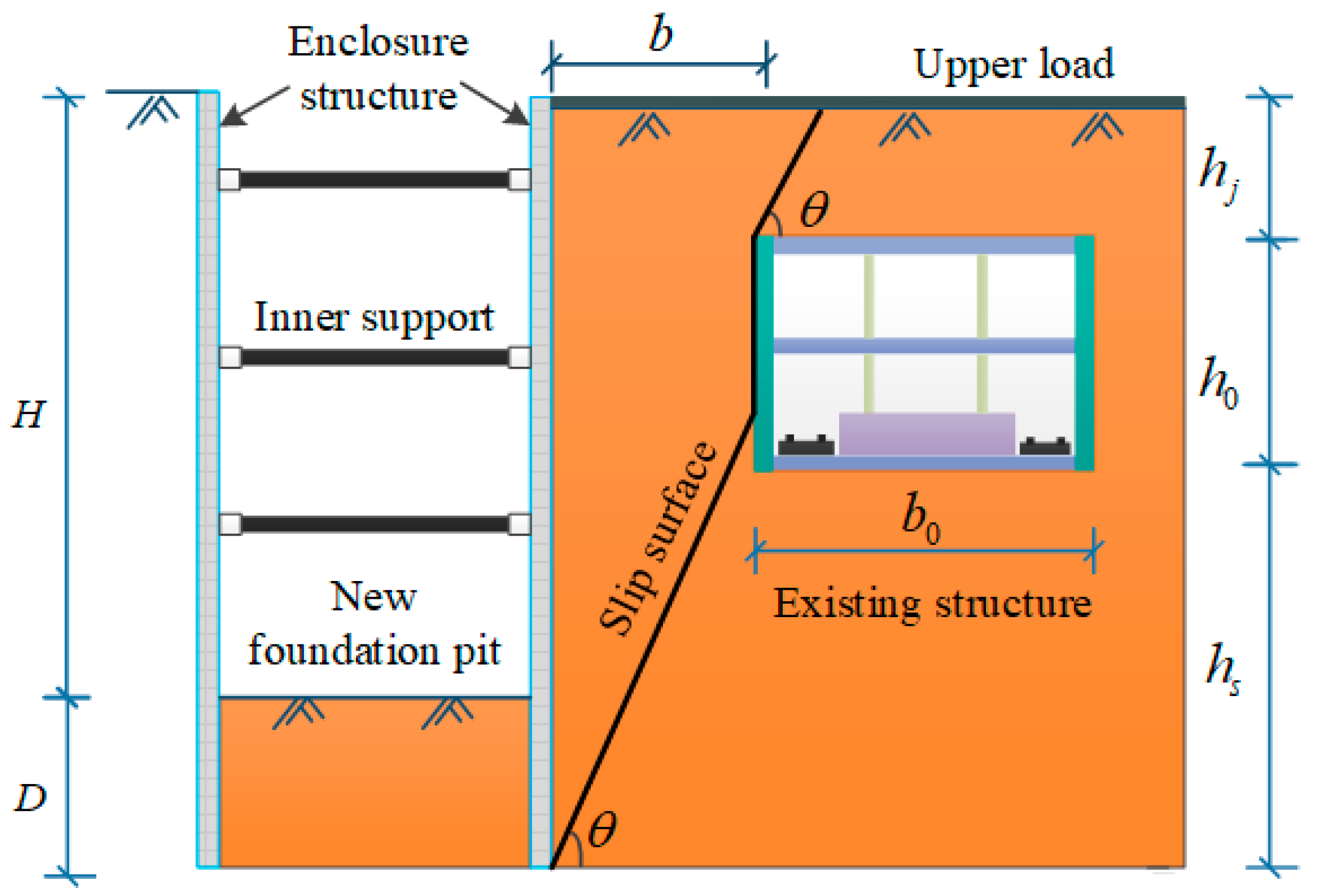
3.1. Mechanical Calculation Model

A slip surface was formed in the soil when a foundation pit was excavated. A nearby existing subway station has an influence on the behavior of this slip surface. The failure mode of soil is shown in Figure 3.
H is the depth of the foundation pit, D is the embedded depth of the enclosure structure, b is the width of the finite soil (the horizontal distance from the foundation pit to the existing subway station), b0 is the width of the existing subway station, hj is the thickness of the overlying soil, h0 is the height of the existing subway station, hs is the distance between the bottom of the enclosure structure and the bottom of the existing subway station, and θ is the inclination angle of the slip surface.

3.2. Assumption

According to the failure mode of soil, the assumptions of the finite soil pressure calculation method are as follows.
(1) The filling surface behind the enclosure structure is horizontal, and the soil is homogeneous and isotropic. (2) There is no cohesion or pore pressure in the soil. The Mohr-Coulomb failure criterion is obeyed. τ = σtanφ, where φ is the soil friction angle. (3) the finite soil between the slip surface and the enclosure structure is considered to slide as a whole, and the shear stresses between two adjacent differential slices are ignored [22]. (4) The existing station is a rectangular subway station built by the open-cut method. (5) The contribution of groundwater is usually neglected.

3.3. Soil Pressure Method Establishment

The failure mode of the soil shown in Figure 4 is that the slip surface is connected with the sidewall of the existing subway station. The soil slip area can be divided into three parts: part Ⅰ, Ⅱ and Ⅲ. The slip surface also includes FG, GC, and CD. Cross D, C and G respectively to make the intersection points of parallel lines and enclosure structure as A, B and E. According to the geometric relationship in Figure 2, the distance b conforms to the following formula:
h s tan ( 45 ° + φ / 2 ) b ( h s + h 0 ) tan ( 45 ° + φ / 2 )

3.3.1. Mechanical Analysis and Equations for Part I

A slice element in part Ⅰ is selected, and its stress is shown in Figure 5 [17].
z is the depth of the slice element, dz is the thickness of the slice element, bs is the upper surface width of the slice element, δ1 is the enclosure structure-soil friction angle, σ is the vertical positive stress on the upper surface of the slice element, (σz + dσ) is the vertical positive stress on the lower surface of the slice element, σx1 is the lateral pressure of the enclosure structure on the soil, τ1 is the shear stress of the enclosure structure on the soil and τ1 = σx1·tanδ1, T is the normal reaction stress acting on the slip plane, τ is the frictional stress acting on the sliding plane and τ = T tanφ, γ is the unit weight of soil, A is the area of the slice element, w is the weight of the slice element and w = γ·A, and q is the ground overload.
According to the geometric relationship in Figure 4 and ignoring the second order and above, the following expression can be obtained:
{ b s = h j + b tan θ z tan θ A = b s d z
The mechanical equilibrium equation for the horizontal direction of the slice element is:
σ x 1 d z + τ c o s θ d z sin θ = T sin θ d z sin θ
According to reference [3], σx1 = ka·σz. ka is the Rankine active soil pressure coefficient.
Simplifying Equation (3) yields:
T = a 1 σ z
where a 1 = k a tan θ ( t a n θ tan φ ) .
The vertical mechanical equilibrium equation for the slice element combined with Equation (4) is:
σ z b s + γ A = ( σ z + d σ ) ( b s d z tan θ ) + τ 1 d z + T c o s θ d z sin θ + τ sin θ d z sin θ
Solving Equation (5),
{ σ z = m 1 ( b tan θ + h j z ) a 2 + γ ( b tan θ + h j z ) a 2 1 σ x 1 = k a σ z
where a2 = ka tanδ1tanθ + a1 tanφtanθ + a1 − 1. m1 is the coefficient.
When z = 0, σz = q, which is substituted into Equation (6), we obtain:
m 1 = [ q γ ( b tan θ + h j ) a 2 1 ] ( b tan θ + h j ) a 2
The value range of z at slip surface CD is 0 to hj. When z = hj, the vertical stress of the BC surface can be obtained.
σ z = h j = m 1 ( b tan θ ) a 2 + γ b tan θ a 2 1

3.3.2. Mechanical Analysis and Equations for Part II

The value range of z at the slip surface GC is hj to hj + h0 + hsbtanθ. A slice element in part Ⅱ is selected, and its stress is shown in Figure 6.
Where δ2 is the subway station-soil friction angle, σx2 is the lateral pressure of the subway station on the soil, τ2 is the shear stress of the subway station on the soil, and τ2 = σx2·tanδ2.
According to the geometric relationship in Figure 4, the area of the slice element A = b·dz and the equilibrium equation for the slice element are established.
{ σ x 1 d z = σ x 2 d z σ z b + γ A = ( σ z + d σ ) b + τ 1 d z + τ 2 d z
Equation (9) is solved to obtain:
{ σ z = m 2 e a 3 z + γ a 3 σ x 1 = k a σ z
where a 3 = k a b ( tan δ 1 + tan δ 2 ) and m2 is a coefficient. When z = hj, substituting Equation (8) into Equation (10) reveals:
m 2 = { [ m 1 ( b tan θ ) a 2 + γ b tan θ a 2 1 ] γ a 3 } e a 3 h j
When z = D + Hbtanθ, the vertical stress on the EG surface is
σ z = D + H b tan θ = m 2 e a 3 ( D + H b tan θ ) + γ a 3

3.3.3. Mechanical Analysis and Equations for Part III

The value range of z at the slip surface FG is hj + h0 + hsbtanθ to hj + h0 + hs. A slice element is selected in part Ⅲ, and its stress is similar to that of part Ⅰ shown in Figure 3. The general solution is in the same form as the part Ⅰ solution.
σ z = m 3 ( H + D z ) a 2 + γ ( H + D z ) a 2 1
σ x 1 = k a σ z
where m3 is a coefficient. When z = D + Hbtanθ, substituting Equation (12) into Equation (13) results in
m 3 = [ m 2 e a 3 ( D + H b tan θ ) + γ a 3 γ b tan θ a 2 1 ] ( b tan θ ) a 2
The enclosure structure is subject to the lateral active soil pressure calculation method, as shown in Equation (15):
{ CD : σ x 1 = k a ( m 1 ( b tan θ + h j z ) a 2 + γ ( b tan θ + h j z ) a 2 1 ) GC : σ x 1 = k a ( m 2 e a 3 z + γ a 3 ) FG : σ x 1 = k a ( m 3 ( H + D z ) a 2 + γ ( H + D z ) a 2 1 ) m 1 = [ q γ ( H + D ) a 2 1 ] ( H + D ) a 2 m 2 = { [ m 1 ( h 0 + h s ) a 2 + γ ( h 0 + h s ) a 2 1 ] γ a 3 } e a 3 h j m 4 = [ q γ ( H + D ) a 2 1 ] ( H + D ) a 2
The magnitude of the resultant force on the enclosure structure with finite soil is
E a = 0 H + D σ x 1 d z
Integrating the soil pressure intensity of each slip surface of CD, GC, and FG in Equation (15) within the depth range provides the resultant force.
E a = k a ( r [ ( h j + b tan θ ) 2 ( b tan θ ) 2 ] 2 ( a 2 1 ) + m 1 [ ( h j + b tan θ ) a 2 + 1 ( b tan θ ) a 2 + 1 ] a 2 + 1 + ( r ( H + D b tan θ ) m 2 e a 3 ( H + D b tan θ ) ) ( r h j m 2 e a 3 h j ) a 3 + r ( b tan θ ) 2 2 ( a 2 1 ) + m 3 ( b tan θ ) a 2 + 1 a 2 + 1 )

3.4. Simple Calculation Method for Resultant Force

According to the previous finite soil pressure calculation method [17] and infinite soil pressure calculation method [15], the soil pressure distribution is nonlinear. In this paper, a simple calculation method for the resultant force of finite soil pressure was proposed with the principle of area equivalence, as shown in Figure 7.
According to the principle of area equality, the original irregular finite soil area S1 is equated to the semi-infinite soil triangle area S2, which can be obtained through the geometric relationship.
{ b 1 = 2 b + h j 2 ( H + D ) tan θ b 2 tan θ H + D θ 1 = arctan ( ( H + D ) 2 tan θ 2 b ( H + D ) tan θ ( b tan θ ) 2 + h j )
Selecting a slice element for AFD1 of the slip surface, the equation is established with reference to the slip of part Ⅰ:
{ σ z = m ( H + D z ) a 5 + γ ( H + D z ) a 5 1 σ x 1 = k a σ z
where a 5 = k a tan δ 1 tan θ 1 + a 4 tan φ tan θ 1 + a 4 1 , a 4 = k a tan θ 1 ( t a n θ 1 tan φ ) , and m is a coefficient. Substituting z = 0 and σz = q into Equation (19) results in
m = [ q γ ( H + D ) a 5 1 ] ( H + D ) a 5
Integrating Equation (19) over the depth range to which it belongs results in the lateral active resultant force of the soil pressure.
E a = 0 H + D σ x 1 d z = k a ( r ( H + D ) 2 2 ( a 5 1 ) + m ( H + D ) a 5 + 1 a 5 + 1 )

3.5. The Relative Height of the Resultant Force

The position of the action point of the resultant force of the soil pressure is a key problem in engineering design. A formula that is too complex is not conducive to the calculation by field workers. The overturning moment of the active soil pressure behind the enclosure structure is given by Equation (22).
M = 0 H + D σ x 1 ( H + D z ) d z = k ( γ h j 3 3 ( a 2 1 ) ( b tan θ ) a 2 m 1 { h j 2 ( 1 + a 2 ) h j [ ( 2 + a 2 ) ( H + D ) + a 2 ( h j + b tan θ ) ] + ( H + D ) ( h j + b tan θ ) ( 2 + a 2 ) ( h j + b tan θ ) 2 a 2 2 + 3 a 2 + 2 } γ h j 2 ( H + D + h j + b tan θ ) 2 ( a 2 1 ) + ( H + D ) ( h j + b tan θ ) γ h j a 2 1 + ( h j + b tan θ ) a 2 m 1 ( ( H + D ) ( h j + b tan θ ) ( 2 + a 2 ) ( h j + b tan θ ) 2 a 2 2 + 3 a 2 + 2 ) + γ ( H + D b tan θ h j ) ( H + D ) γ [ ( H + D b tan θ ) 2 h j 2 ] 2 + m 2 e a 3 ( H + D b tan θ ) ( 1 a 3 b tan θ ) m 2 e a 3 h j ( h j + 1 a 3 H D ) a 3 ( γ ( b tan θ ) 3 3 ( a 2 1 ) + m 3 ( b tan θ ) a 2 + 2 a 2 + 2 ) )
The overturning moment of the active soil pressure behind the enclosure structure using the simple method is given by Equation (23).
M = k ( r ( H + D ) 3 3 ( a 5 1 ) + m ( H + D ) a 5 + 2 ( a 5 + 2 ) )
Ψ is the relative height of the resultant force, which is the ratio of the distance from the action point to the enclosure structure bottom and the enclosure structure depth. Substituting Equations (17) and (22) into Equation (24) provides Ψ.
ψ = M E a ( H + D )
The Ψ of the simple method can be calculated according to Equation (25).
ψ = k ( r ( H + D ) 3 3 ( a 5 1 ) + m ( H + D ) a 5 + 2 ( a 5 + 2 ) ) k ( r ( H + D ) 3 2 ( a 5 1 ) + m ( H + D ) a 5 + 2 a 5 + 1 )

4. Example Verification

An example is given here, considering the following parameters: q = 0 kN/m3, r = 16.2 kN/m3, c = 0 kPa, φ = 35°, δ1 = δ2 = 20°, H = 18.7 m, D = 6.3 m, hj = 0 m, h0 = 12.4 m, hs = 12.6 m, b0 = 21.2 m, and b = 10 m. According to the geometric relationship, this calculation method is applicable to the model in this paper. The calculation results obtained by using Rankine theory, the reference method [18], the proposed method, and the simple method are shown in Figure 8 and Figure 9.
Previous studies have shown that finite soil pressure is less than that of infinite soil [2]. The finite soil pressures obtained by the proposed method, the simple method, and the method in reference [18] are much less than the calculated value of Rankine theory (Figure 8 and Figure 9), and the soil pressure is nonlinearly distributed. The soil pressure increases gradually with depth and then decreases abruptly. The values and trends of the finite soil pressure obtained between the proposed method and the method in reference [18] completely coincide. The soil pressure difference between the simple method and the method proposed in this paper is very small.
The proposed method is applicable to the case in which a new foundation pit is adjacent to an existing subway station. When the overlying soil thickness of the existing structure is zero, the proposed method can be simplified to the calculation method in reference [18]. Therefore, the calculation method in reference [18] is a special case of the proposed calculation method. Therefore, in the above calculation examples, the calculation results of reference [18] are consistent with those of the method proposed in this paper.

5. Comparative Verification of Model Test

5.1. Model Overview

Model tests were conducted to investigate the finite soil pressure for a new foundation pit adjacent to an existing subway station. The model test section is shown in Figure 10. The size of the model box is 1.50 m long, 0.74 m wide, and 1.20 m high, and the size of the existing subway station is 33 cm wide, 74 cm long, and 21.6 cm high. The foundation pit was designed with a 50 mm depth and 40 mm width. The depth of the enclosure structure is 70 mm.
The similar soil in the model test was sandy soil. The raw materials of the similar soil were barite powder, standard sand, gypsum powder, oil, and water, of which the oil acts as a bonding material (Figure 11). The total weight is 1 kg, and the mass of each material is shown in Table 1.
The direct shear test was used to determine the strength index of soil, and the relationship curve between shear strength and vertical pressure was drawn according to the measured data, as shown in Figure 12.
Moreover, its main physical and mechanical properties were set according to the test results, as shown in Table 2.
The braced system of the foundation pit includes an inner support structure and an enclosure structure. A PVC pipe with a thickness of 2 mm was used as the foundation pit support structure. Plexiglas panels with 8 mm thicknesses were used as the enclosure structure of the foundation pit. The soil pressure cells, which are instruments for testing soil pressure, were arranged vertically along the center of the longitudinal length of the enclosure structure, as shown in Figure 10. The soil pressure test instrument selected a BX-1 resistance soil pressure box. The range of the soil pressure box is 10 kPa, and the soil pressure box was calibrated before the test. The soil pressure value was obtained by converting the strain data collected by the multi-function strain collection instrument during the test. The soil pressure box and multi-function strain gauge used in the test are shown in Figure 13.
A standard two-story, three-span structure was chosen for the existing subway station. The Plexiglas panels are the structural members of the existing subway station. The top and bottom plates are Plexiglas panels with 8 mm thicknesses, the middle plate is a Plexiglas panel with a 4 mm thickness, the sidewalls are Plexiglas panels with 6 mm thicknesses, and the columns are Plexiglas cylinders with a radius of 10 mm.

5.2. Test Implementation

The test process included the installation of the filling and related structures, the soil excavation, and the inner support erection. Pave sand from bottom to top. The height of the model box is 1.5 m. The soil samples are filled in 10 layers. After each layer was paved, stewing it for half an hour. When the soil layer was filled with 50 cm, it was buried into the enclosure structure. Three internal supports were designed at 5 cm, 20 cm, and 35 cm, respectively.
The manual layered excavation was applied. The designed excavation depth is 50 cm, which is divided into 12 layers, and each excavation is approximately 4.2 cm. The specific implementation is shown in Figure 14.

5.3. Analysis of Test Results

According to reference [23], the model δ1 = δ2 = 2/3 φ. The other length parameters in the model test are H = 0.5 m, D = 0.2 m, hj = 0.1 m, h0 = 0.2 m, and hs = 0.4 m.
The results of the model test, finite soil pressure calculation method, and Rankine soil pressure calculation method proposed in this paper are shown in Figure 15 and Figure 16.
Figure 15 shows that the finite soil pressure distribution is nonlinear, with the soil pressure increasing gradually at first and then decreasing abruptly. The model test results also showed that the finite soil pressure is less than the soil pressure obtained from Rankine theory. The soil pressure distribution trend of the finite soil proposed in this paper is basically consistent with the soil pressure distribution trend of the model test. From Figure 16, it can be seen that the magnitudes of the combined soil pressure of the two methods and the model test are similar and significantly lower than that of Rankine theory.

6. Parametric Analysis

In this section, the influences of some parameters were explored. The initial values of the parameters were γ = 16.2 kN/m3, c = 0 kPa, φ = 35°, δ1 = δ2 = 20°, H = 18.7 m, D = 6.3 m, hj = 4.6 m, h0 = 12.4 m, hs = 8 m, b0 = 21.2 m, and b = 10 m. Then, the value of a parameter is changed, and the influence of this parameter on the calculation results was explored.

6.1. Calculation Process

In the present method, we substituted the parameters in Equation (15) to obtain the soil pressure intensity distribution, Equation (17) to obtain the resultant force, and Equation (24) to obtain the resultant force action point in this paper. Meanwhile, in the simple method, we substituted the parameters in Equation (19) to obtain the soil pressure intensity distribution, Equation (21) to obtain the resultant force, and Equation (25) to obtain the resultant force action point in this paper.
The specific calculation flow of the above two methods is shown in Figure 17.

6.2. Parametric Analysis for Soil Pressure

6.2.1. Influence of the Spatial Relationship on Ea

The influence of the spatial relationship between the foundation pit and the existing subway station on the resultant force of a finite amount of soil was studied. The spatial relationship included the thickness of the overlying soil hj and the width of the finite soil b. The calculation results are shown in Figure 18 and Figure 19.
Figure 18 and Figure 19 show the influence of overlying soil thickness and the finite soil width on Ea, indicating that the resultant force of a finite amount of soil is quite different from the Rankine soil pressure. This force increases with increasing hj and b. However, the influence is very small because the changes in hj and b cause no change in the slip surface inclination angle and only a small change in the soil slip area.

6.2.2. Influence of Friction Angles on Ea

The influences of the friction angles on the resultant force of a finite amount of soil were studied. The friction angles include the internal friction angle φ, the friction angle between the enclosure structure and soil δ1, and the friction angle between the existing subway structure and soil δ2. For the friction angle between the structure and soil, δ, δ1 = δ2 = δ is assumed to simplify the parameters [1]. The calculation results are shown in Figure 20 and Figure 21.
Figure 20 shows that the resultant force of soil pressure is non-linearly decreasing with the increase of φ. Furthermore, the effect is very significant. With the increase of internal friction angle, the area of the slip soil decreases, which leads to the weakening of the vertical stress of the soil, and the shear stress on the slip surface increases. Figure 21 shows that the resultant force of soil pressure is also decreasing with the increase of δ because the increase of structure-soil friction angle δ causes the interface friction between soil and structure.

6.2.3. Influence of Ground Overload and Unit Weight on Ea

The influences of the ground overload q and unit weight γ on the resultant force of a finite amount of soil were studied. The corresponding calculation results are shown in Figure 22 and Figure 23.
Figure 22 and Figure 23 show that the resultant force of the finite soil increases with increasing ground overload and unit weight because the ground overload and unit weight both increase the vertical stress of the soil.

6.3. Parametric Analysis for the Resultant Force Relative Height

In this section, the influence of a friction angle on the resultant force of a finite amount of soil was studied. Here, the friction angle is similar to that in Section 6.2.2. The calculation results are shown in Figure 24 and Figure 25.
Figure 24 shows that the relative height of the resultant force Ψ increases with increasing structure-soil friction angle δ. The results of the simple method are close to those of the proposed method. When δ = 0, ψ = 1/3, which is consistent with the Rankine theory solution. Furthermore, the increasing trend of the relative height of the resultant force with increasing δ is consistent with that in reference [18].
Figure 25 shows that Ψ of the proposed method and the simple method decreases with increasing internal friction angle φ, but the difference with the Rankine theory solution is large. Reference [2,29] verified that Ψ is greater than or equal to 1/3 for finite soil by means of finite element and model tests, respectively; obviously, the results in this paper are consistent.

7. Conclusions

In this paper, based on the situation of a new foundation pit adjacent to an existing subway station, the formulas for calculating the finite soil pressure were derived with the horizontal differential element method and a simple calculation method for the resultant force of a finite amount of soil and the height of the action point were proposed with the principle of area equivalence. With the example and model tests, the rationality of the above method was verified. The influence of the parameters on the resultant force of the soil pressure and the height of the action point was analyzed. The main conclusions were obtained as follows.
  • The finite soil pressure has a nonlinear distribution and is lower than the conventional soil pressure.
  • Compared with other existing methods and model test results, the proposed finite soil pressure calculation method and simplified method are rational.
  • The finite soil pressure increases with the ground overload and soil weight and decreases with the internal friction angle and structure-soil friction angle.
  • The action point height of the finite soil resultant force increases with the structure-soil friction angle and decreases with the internal friction angle.
  • The proximity and covering soil thickness of the existing subway station have less influence on the finite soil pressure. The internal friction angle, weight, structure-soil friction angle and ground overload have a greater influence on the finite soil pressure.
  • The structure-soil friction angle has a greater influence on the height of the action point. The height of the action point is one-third of the diaphragm wall depth if the structure-soil friction angle is 0.

Author Contributions

Conceptualization, Z.Z. and Z.L.; methodology, Z.Z. and J.Z.; software, J.Z.; validation, Z.Z., J.Z. and F.X.; formal analysis, J.Z. and F.X.; investigation, M.S.; resources, F.X. and Z.L.; writing—original draft preparation, J.Z.; writing—review and editing, Z.Z., F.X. and Z.L. All authors have read and agreed to the published version of the manuscript.

Funding

This research is supported by the “Science and Technology Project of Hebei Education Department (No. QN2021130)”, the “National Natural Science Foundation of China (No. 52078311)”, and the “Young Talent Top Project of Hebei Province (No. BJ2020055)”, the technical support from Shijiazhuang TieDao University.

Institutional Review Board Statement

Not applicable.

Informed Consent Statement

Not applicable.

Data Availability Statement

Not applicable.

Conflicts of Interest

The authors declare no conflict of interest.

References

  1. Wang, H.L.; Song, E.X.; Song, F.Y. Calclulation of active earth pressure for limited soil between existing building and excavation. Eng. Mech. 2014, 31, 76–81. [Google Scholar]
  2. Fan, C.C.; Fang, Y.S. Numerical solution of active earth pressures on rigid retaining walls built near rock faces. Comput. Geotech. 2010, 37, 1023–1029. [Google Scholar] [CrossRef]
  3. Frydman, S.; Keissar, I. Earth pressure on retaining walls near rock faces. J. Geotech. Eng. ASCE 1987, 113, 586–599. [Google Scholar] [CrossRef]
  4. Take, W.A.; Valsangkar, A.J. Earth pressures on unyielding retaining walls of narrow backfill width. Can. Geotech. J. 2001, 38, 1220–1230. [Google Scholar] [CrossRef]
  5. Khosravi, M.H.; Pipatpongsa, T.; Takemura, J. Experimental analysis of earth pressure against rigid retaining walls under translation mode. Geotechnique 2013, 63, 1020–1028. [Google Scholar] [CrossRef]
  6. Rui, R.; Ye, Y.Q.; Han, J.; Zhang, L.; Zhai, Y.X. Experimental and theoretical investigations on active earth pressure distributions behind rigid retaining walls with narrow backfill under a translational mode. Int. J. Geomech. 2020, 20, 04020178. [Google Scholar] [CrossRef]
  7. Yang, M.H.; Tang, X.C.; Wu, Z.Y. Slip surface and active earth pressure of cohesionless narrow backfill behind rigid retaining walls under translation movement mode. Int. J. Geomech. 2020, 20, 04020115. [Google Scholar] [CrossRef]
  8. Ma, P.; Qin, S.Q.; Qian, H.T. Calculation of active earth pressure for limited soils. Chin. J. Rock Mech. Eng. 2008, 27, 3070–3074. [Google Scholar]
  9. Hu, W.D.; Zhu, X.N.; Liu, X.H.; Zeng, Y.Q.; Zhou, X.Y. Active earth pressure against cantilever retaining wall adjacent to existing basement exterior wall. Int. J. Geomech. 2020, 20, 04020207. [Google Scholar]
  10. Greco, V. Active thrust on retaining walls of narrow backfill width. Comput. Geotech. 2013, 50, 66–78. [Google Scholar] [CrossRef]
  11. Greco, V. Analytical solution of seismic pseudo-static active thrust acting on fascia retaining walls. Soil Dyn. Earthq. Eng. 2014, 57, 25–36. [Google Scholar] [CrossRef]
  12. Shaik, M.A.; Munwar, B.B. Seismic active earth pressure on narrow backfill retaining walls considering strain localization. Indian Geotech. J. 2021, 51, 1–20. [Google Scholar]
  13. Chen, F.Q.; Lin, Y.J.; Li, D.Y. Solution to active earth pressure of narrow cohesionless backfill against rigid retaining walls under translation mode. Soils Found 2019, 59, 151–161. [Google Scholar] [CrossRef]
  14. Chen, F.Q.; Yang, J.T.; Lin, Y.J. Active earth pressure of narrow granular backfill against rigid retaining wall near rock face under translation mode. Int. J. Geomech. 2019, 19, 04019133. [Google Scholar] [CrossRef]
  15. Wang, Y.Z. Distribution of earth pressure on a retaining wall. Geotechnique 2000, 50, 83–88. [Google Scholar] [CrossRef]
  16. Kumar, J.; Reimbert, A.M. Discussion: Distribution of earth pressure on a retaining wall. Geotechnique 2002, 52, 231. [Google Scholar] [CrossRef]
  17. Chen, J.J.; Li, M.G.; Wang, J.H. Active Earth Pressure against Rigid Retaining Walls Subjected to Confined Cohesionless Soil. Int. J. Geomech. 2017, 17, 06016041. [Google Scholar] [CrossRef]
  18. Ying, H.W.; Huang, D.; Xie, X.Y. Study of active earth pressure on retaining wall subject to translation mode considering lateral pressure on adjacent existing basement exterior wall. Chin. J. Rock Mech. Eng. 2011, 30, 2970–2978. [Google Scholar]
  19. Handy, R. The arch in soil arching. J. Geotech. Eng. ASCE 1985, 111, 302–318. [Google Scholar] [CrossRef]
  20. Liu, M.L.; Chen, X.S.; Hu, Z.Z.; Liu, S.Y. Active Earth Pressure of Limited c-φ Soil Based on Improved Soil Arching Effect. Appl. Sci. 2020, 10, 3243. [Google Scholar] [CrossRef]
  21. Hu, W.D.; Liu, K.X.; Zhu, X.N.; Tong, X.L.; Zhou, X.Y. Active earth pressure against rigid retaining walls for finite soils in sloping condition considering shear stress and soil arching effect. Adv. Civ. Eng. 2020, 2020, 6791301. [Google Scholar] [CrossRef]
  22. Xie, M.X.; Zheng, J.J.; Zhang, R.J.; Cui, L.; Miao, C.X. Active earth pressure on rigid retaining walls built near rock faces. Int. J. Geomech. 2020, 20, 04020061. [Google Scholar] [CrossRef]
  23. Xu, R.Q.; Xu, Y.B.; Chen, K.; Feng, S.Y.; Shen, S. Method to calculate active earth pressure considering soil arching effect under nonlimit state of clay. Chin. J. Geotech. Eng. 2020, 42, 362–371. [Google Scholar]
  24. Smita, P.; Kousik, D. Study of active earth pressure behind a vertical retaining wall subjected to rotation about the base. Int. J. Geomech. 2020, 20, 04020028. [Google Scholar]
  25. Chen, F.Q.; Lin, Y.J.; Yang, J.T.; Huang, M. Passive earth pressure of narrow cohesionless backfill against rigid retaining walls rotating about the base. Int. J. Geomech. 2021, 21, 06020036. [Google Scholar] [CrossRef]
  26. Chen, F.Q.; Lin, C.; Lin, L.B.; Huang, M. Active earth pressure of narrow cohesive backfill on rigid retaining wall of rotation about the bottom. Soils Found 2021, 61, 95–112. [Google Scholar] [CrossRef]
  27. Lai, F.W.; Yang, D.Y.; Liu, S.Y.; Zhang, H.B.; Cheng, Y.H. Towards an improved analytical framework to estimate active earth pressure in narrow c-φ soils behind rotating walls about the base. Comput. Geotech. 2022, 141, 104544. [Google Scholar] [CrossRef]
  28. Yang, D.Y.; Lai, F.W.; Liu, S.Y. Earth pressure in narrow cohesive-fictional soils behind retaining walls rotated about the top: An analytical approach. Comput. Geotech. 2022, 149, 104849. [Google Scholar] [CrossRef]
  29. Yang, M.H.; Tang, X.C. Rigid retaining walls with narrow cohesionless backfills under various wall movement modes. Int. J. Geomech. 2017, 17, 04017098. [Google Scholar] [CrossRef]
  30. Vishwajit Anand, S.R.; Satish, K. Seismic Soil-structure Interaction: A State-of-the-Art Review. Structures 2018, 16, 317–326. [Google Scholar] [CrossRef]
  31. Javier, A.; Luis, P.R. Soil–structure interaction in yielding systems. Soil. Eng. Struct. 2003, 32, 1749–1771. [Google Scholar]
  32. Marco, Z.; Pietro, G.C.; Nicola, L.; Manuela, A.S. The new foundation system of the Basilica di Collemaggio’s transept. Int. J. Mason. Res. Innov. 2020, 5, 67–84. [Google Scholar]
  33. Ying, H.W.; Zhang, J.H.; Wang, X.G.; Li, B.H.; Zhu, W. Experimental analysis of passive earth pressure against rigid retaining wall under translation mode for finite soils. Chin. J. Geotech. Eng. 2016, 38, 978–986. [Google Scholar]
  34. Deng, B.; Yang, M.H.; Zhao, M.H. Experimental study on failure mode and lateral earth pressure distribution of unsaturated sand behind retaining walls under active translation mode. Chin. J. Geotech. Eng. 2023, 45, 94–102. [Google Scholar]
Figure 1. Plane position of new foundation pit and existing entrance and exits.
Applsci 13 01994 g001
Figure 2. Comparison of soil pressure distribution.
Applsci 13 01994 g002
Figure 3. Soil failure mode.
Applsci 13 01994 g003
Figure 4. Calculation model of finite soil pressure.
Applsci 13 01994 g004
Figure 5. A slice element mechanical model of part I.
Applsci 13 01994 g005
Figure 6. A slice element mechanical model of part II.
Applsci 13 01994 g006
Figure 7. Area equivalence diagram.
Applsci 13 01994 g007
Figure 8. Distribution of finite soil pressure compared with those of previous studies [18].
Applsci 13 01994 g008
Figure 9. Resultant force of finite soil pressure compared with those of previous studies.
Applsci 13 01994 g009
Figure 10. Model test section.
Applsci 13 01994 g010
Figure 11. Raw materials of similar soil.
Applsci 13 01994 g011
Figure 12. Relation curve between shear strength and vertical pressure.
Applsci 13 01994 g012
Figure 13. Soil pressure test instrument. (a) Soil pressure box, (b) Multi-function strain gauge.
Applsci 13 01994 g013
Figure 14. Model test implementation diagram. (a) Fill to enclosure structure top elevation, (b) Soil excavation-inner support erection.
Applsci 13 01994 g014
Figure 15. Distribution of finite soil pressure compared with experiment.
Applsci 13 01994 g015
Figure 16. Resultant force of finite soil pressure compared with experiment.
Applsci 13 01994 g016
Figure 17. Calculation flow chart.
Applsci 13 01994 g017
Figure 18. The influence of overlying soil thickness.
Applsci 13 01994 g018
Figure 19. The influence of finite soil width.
Applsci 13 01994 g019
Figure 20. The influence of internal friction angle.
Applsci 13 01994 g020
Figure 21. The influence of structure-soil friction angle.
Applsci 13 01994 g021
Figure 22. The influence of the ground overload.
Applsci 13 01994 g022
Figure 23. The influence of the unit weight.
Applsci 13 01994 g023
Figure 24. Relation curves of ψ and δ.
Applsci 13 01994 g024
Figure 25. Relation curves of ψ and φ.
Applsci 13 01994 g025
Table 1. Specific gravity of similar soil.
Barite Powder/gStandard Sand/gGesso/gEngine Oil/gBentonite/gWater/g
164.31657.2320.5447.92011
Table 2. Physical and mechanical indexes of test soil samples.
φ/(°)c/kPaγ/(kN·m−3)Es/Mpa
30018.57.14
Disclaimer/Publisher’s Note: The statements, opinions and data contained in all publications are solely those of the individual author(s) and contributor(s) and not of MDPI and/or the editor(s). MDPI and/or the editor(s) disclaim responsibility for any injury to people or property resulting from any ideas, methods, instructions or products referred to in the content.

