Abstract
In response to the worldwide shortage of 99mTc supply caused by the combined consequence from both decommissioning and maintenance of research reactors worldwide, the Institute of Modern Physics (IMP) of the Chinese Academy of Science and Lanzhou University have launched a collaboration to research and develop a 99mTc production solution based on the 25 MeV high-intensity superconducting proton linear accelerator. Radiation from high-current proton bombardment must be evaluated and considered carefully at the design stage to meet radiation protection (RP) policy and requirements of the shielding for the key device. This work employed FLUKA to conduct the shielding assessment of both prompt and residual radiation fields in several iterations, based on a prototype of the high-power target system. The prompt dose rates outside the target station are lower than the institution’s limit. The residual dose rates inside the station fall below 100 μSv/h at 64 h after the end of beam (EOB); the dominant source term is then the target chamber. The service life of the main actuator is expected to be extended by 2.7 times with the current partial shielding design. The simulation accelerating techniques are applied to balance the accuracy of results and the progress of the project at the same time, which is referential to the shielding assessment of large-scale nuclear facilities. The results can also be used in further study and construction of the target station.
1. Introduction
As a fundamental tool in nuclear medicine procedures, radiopharmaceuticals are unique compounds generally composed of ligands and radioisotopes. The ligands selectively transport medical isotopes to designated tissues or organs and eventually combine with them. The decay of the isotopes emits radiation that can be used for medical diagnosis or treatment. One of the most critical medical isotopes, 99mTc, has a half-life of 6.01 h and emits 140 keV photons during decay. Currently, 99mTc is one of the most widely used medical isotopes in the world. It is used in more than 85% of the nuclear medicine diagnostic processes [], typically in single photon emission computed tomography (SPECT) after pharmaceutical processing []. In China, the supply of 99mTc relies on imports due to the lack of domestic production facilities. The activity of 99Mo/99mTc imported to China in 2019 attains ~63% of the total activity of all imported radioisotopes [].
Owing to the relatively short half-life of 99mTc, its general production process involves irradiating enriched uranium targets with high-flux neutrons produced by a reactor to produce 99Mo (T1/2 = 66 h) through fission reactions. After the irradiated target is dissolved and purified, the processed solution is supplied to a 99Mo-99mTc generator to be distributed to medical facilities for clinical or research use. In the hospital, technetate (99mTcO4−) solution for pharmaceuticals is eluted with saline as needed. However, except for the Open Pool Australian Lightwater (OPAL) reactor, other reactors producing 99Mo have been operating for more than 50 years and are facing decommissioning or frequent maintenance [,]. Consequently, since 2009, some countries have been experiencing serious global shortages of medical isotopes due to the shutdown of research reactors []. The development of alternative 99mTc production methods has received extensive attention. The most promising ones are as follows:
- Production of 99Mo based on a high-current neutron generator and fission reaction [];
- Production of 99mTc using a proton cyclotron [];
- Production of 99Mo based on a high-energy electron linear accelerator that exploits photonuclear reactions [].
Among them, the Canadian National Laboratory of Particle and Nuclear Physics (TRIUMF) has verified the feasibility of the method for direct production of 99mTc based on their TR-24 cyclotron [,].
The China Initiative Accelerator Driven System (CiADS) is a scientific program proposed by the Chinese Academy of Science (CAS) to solve the problems of nuclear waste and fuel. The 25 MeV superconducting (SC) linear accelerator prototype in the Institute of Modern Physics (IMP) was designed and built as the demonstration facility for the intense proton source for this system []. One of the experimental terminals was allocated to investigate the production of 99mTc via the 100Mo (p,2n) 99mTc reaction.
The high-current proton beam can produce intense secondary radiations when bombarding a highly enriched 100Mo target. The secondary particles generated, such as neutrons and photons, must be properly shielded for the safety of personnel and avoidance of damage to crucial elements sensitive to radiation.
In this work, we performed a shielding assessment and optimization of the experimental terminal that considers both prompt and residual radiation together with the effect of nuclear activation from the components of the target system and the building infrastructure.
2. Materials and Methods
2.1. High-Power Target System Development
The high-power target system is the main device for medical isotope production. It must meet two requirements: (1) the target is sufficiently cooled to prevent overheating and melting, which could lead to vacuum device damage and radiation leakage; (2) target processing must be handled remotely due to high residual dose rate from the target and other surrounding components []. A prototype of the high-power target system was developed for 99mTc production based on the IMP superconducting proton linac, as shown in Figure 1. The system provides a 24 MeV and 500 μA proton beam for continuous irradiation of a highly enriched 100Mo target. The target system consists of three subsystems:
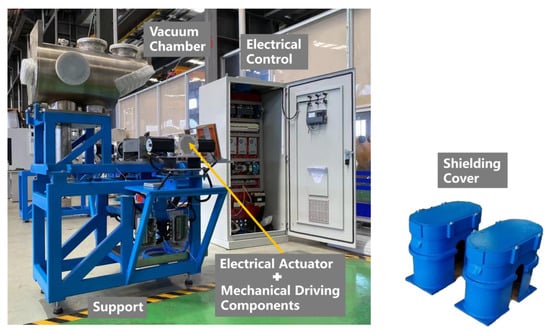
Figure 1.
High-power target system developed by Lanzhou University.
- (1)
- Vacuum system: The vacuum system is mainly composed of a vacuum chamber made of SS316L and a Leybold turbomolecular pump unit. Ten different flange interfaces are reserved for beam diagnostics and vacuum control elements. A high-fluorine rubber ring seal is used between the target and the chamber. Considering the connection to the front-end superconducting linear accelerator, the ultimate vacuum of the chamber should reach a value of 1 mPa (~7.5 nTorr), and the leak rate lower than 10−10 mbar·L/s. The leak rate of the system is tested to be less than 10−12 mbar·L/s in the atmosphere and the ultimate pressure drops significantly faster, reaching 1 mPa (~7.5 nTorr) within 24 h after baking, both lower than the design parameters [].
- (2)
- Target and cooling system: The target is composed of a substrate made of oxygen-free copper for its high thermal conductivity, and an enriched 100Mo coating. The upper part of the substrate features six cooling fins inside to improve heat dissipation, as shown in Figure 2. The system can meet the target cooling requirement given a continuous irradiation with a 12 kW proton beam as per theoretical calculation with a one-dimensional heat equation and computational fluid dynamics (CFD) simulation [].
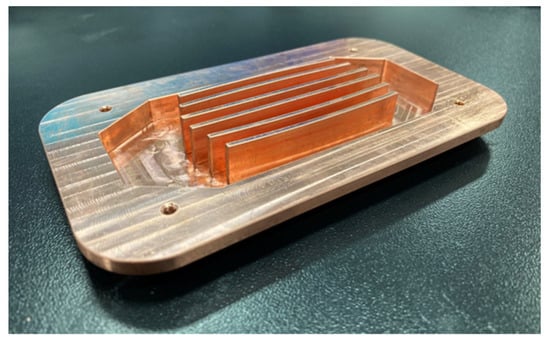 Figure 2. Inside view of the upper part of the target substrate, showing the six cooling fins.
 - (3)
- Driving and autocontrol system: Mechanical components and electrical actuators are coordinated to realize the functions of manipulator driving, target locking, and safety interlock. The feedback and control of the system are realized through programmable logic controller (PLC) programming with Siemens S7-1200 controllers. The system has two controlling modes. The manual mode is used in offline tests, while the remote (automatic) mode is used during the online experiment to ensure personnel safety.
The geometric model constructed in the following simulation is based on the as-built target system to ensure the evaluation accuracy of the dose equivalent rate distributions and residual activation. A partial shielding cover is designed and manufactured for the protection of stepper motors from prompt radiation, which is detailed in Section 3.4.
2.2. Shielding Requirements
Shielding was designed to meet the regulatory dose limits and the “ALARA” principle [] was taken into consideration for this work. According to the national standard [], the annual average cumulative dose of nuclear workers shall not exceed 20 mSv for five consecutive years, while the value for the public shall not exceed 5 mSv. Referring to IMP’s RP policy, a quarter of the personnel dose limit and one-tenth of the public dose limit specified in the national standard were used in radiation protection design goals and operation.
As per the standards detailed above, since the region outside the target terminal zone is designed to be a low occupancy area during beam irradiation, the dose rate limit is set at 2.5 μSv/h. Since the upper layer of the terminal zone is accessible to the public, it is treated as an area with high occupancy and whose dose rate should not exceed 0.25 μSv/h. The zone inside the terminal is an exclusion area during beam irradiation. For nuclear workers who may need to enter the terminal to carry out transient maintenance work between operations or shutdown, the dose rate limit is set at 100 μSv/h while their accumulated dose must be in line with the policy requirements.
2.3. Simulation Model
The simulation platform used in this study was the Monte Carlo (MC)-based particle transport and interaction simulation software, FLUKA (version 4-1.1) []. FLUKA has been thoroughly validated and widely used for radiation protection calculation and shielding design of accelerator facilities such as CERN’s Large Hadron Collider (LHC) []. The simulation modeling has three primary sections:
- (1)
- Physical model: The simulations used the PRECISION default physical settings in FLUKA. The cutoff transport energy of the photon was set at 20 keV. In addition, coalescence and evaporation models were applied for the simulation concerning the decay of the compound nucleus.
- (2)
- Beam parameter: The shielding assessment was based on the scenario in which the accelerator power is 12 kW (24 MeV; 500 μA) and the proton beam continuously bombards the 100Mo target for 6 h. The BEAM and BEAMPOS card were used to set the beam energy, profile, and incident direction. The IRRPROFI, DCYTIMES, and RADDECAY cards were activated to set the beam intensity, irradiating profile, and decay time for the simulation of residual radiation.
- (3)
- Geometric model: The 100Mo target is placed at 30° with respect to the horizontal plane, as shown in Figure 3, to reduce the burden of heat generation on the target cooling system. The target surface size is 9 cm × 18 cm, with a coating of 250 μm 100Mo in thickness. The geometric and material model of the target system was established based on the realistic mechanical design. However, owing to the complexity of the structure, the model was simplified to a certain extent without essentially affecting the general results and conclusions. The whole geometry was constructed with the combinatorial geometry (CG) tool in Flair [], as shown in Figure 4.
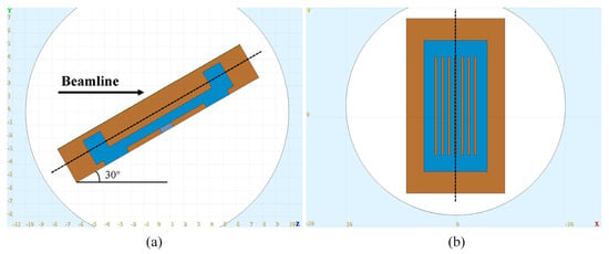 Figure 3. Target geometry: (a) side view section and (b) top view section. Distances are given in cm.
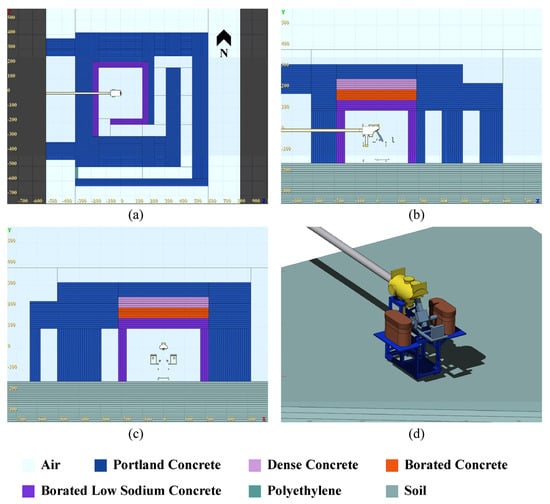 Figure 4. (a–c) Cross-sectional view of the experimental terminal geometry. (d) Three-dimensional model of the target system in Flair. Distances are given in cm.
2.4. Simulation Method
Because of the large-scale size of the experimental terminal with heavy shielding, particle fluence is sharply reduced when passing through the shielding materials. Therefore, two variance reduction methods were used to enhance the statistics of the simulation results.
Method 1 was realized by the user subroutine usimbs.f in FLUKA, with an approach similar to that employed in Ref. []. The main program calls this routine at each step of the particle transport and assigns the relative weight according to customized conditions, which are based on the attenuation length and the distance between the track hit and the source point. Only neutrons and photons were accounted for in the biasing due to their importance in deep shielding penetration. The relative importance was incremented gradually with the distance between the particle hit and the 100Mo target.
Method 2 sets incrementing importance values for the regions along the approximate transport direction of particles []. The importance-setting map of the experimental terminal area is displayed in Figure 5.
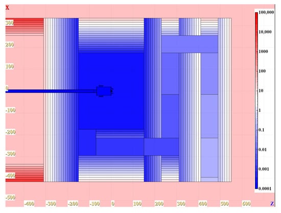
Figure 5.
Region importance biasing (10−4~105). Distances are given in cm.
The effects of the different variance reduction methods were compared, as shown in Figure 6. Both the methods could significantly improve the statistics of events after penetrating the shielding body. Method 2 provided a better result according to the comparison.
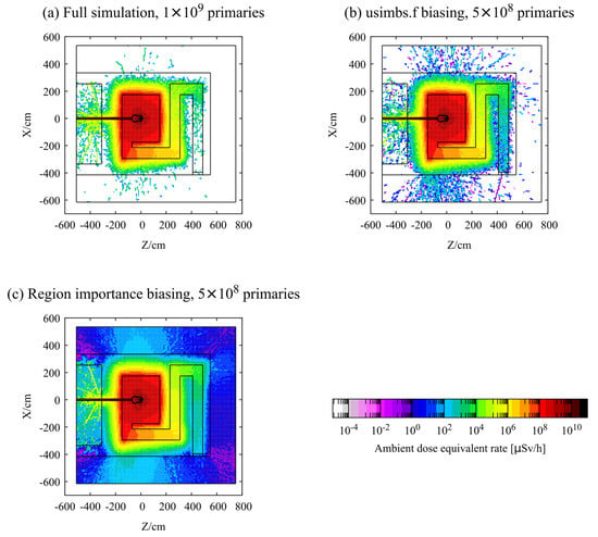
Figure 6.
Prompt ambient dose equivalent (in μSv/h) at beam level with and without biasing. The usage of biasing techniques improves the statistics, especially in the area far from the source term, even with fewer primaries.
The CPU chip used in the calculation was the Intel(R) Xeon(R) Gold 6240 CPU @ 2.60 GHz. The average time per primary in Method 1 (6.4 × 10⁻⁵ s/primary) and Method 2 (7.8 × 10⁻⁵ s/primary) are, respectively, 6.3 and 7.7 times full-simulation (1.0 × 10⁻⁵ s/primary). If the geometry buildup time is considered, the total time consumption for Method 2 is much longer. Thus, when encountering shielding issues during management of large-scale nuclear facilities based on FLUKA, weighing the accuracy of simulation results and the progress of the project at the same time, the following simulation strategy should be considered:
- (1)
- Carry out a full simulation based on construction drawings to record the source-term energy spectrum and then select appropriate shielding materials based on physical models;
- (2)
- Utilize Method 1 to improve the statistics of simulation results and iterate the shielding design within a relatively short time, and then evaluate and optimize the design of key parts such as mazes and ventilation penetrations. Method 1 can also be better customized by creating more layers or adjusting the biasing factor, which may finally provide a satisfactory result, but with more time.
- (3)
- If necessary and/or feasible, perform regional segmentation of the geometric model and assign importance to achieve more accurate simulation results. Method 2 is not applicable if the geometry is too complicated.
3. Results
3.1. Shielding Material Composition
The USRBDX card in FLUKA was used to score the fluences of secondary particles passing through a vacuum sphere (radius = 10 cm) with the geometric center of the target surface. The source-term fluence distribution of neutrons and photons crossing the sphere are shown in Figure 7.
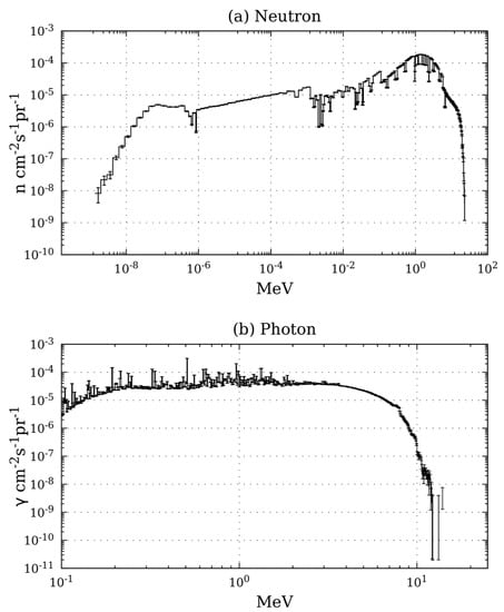
Figure 7.
Neutron and photon fluences generated during the irradiation of 100Mo target using a 24 MeV proton beam with intensity of 500 μA.
Three shielding materials for both neutrons and photons were considered: Portland concrete without and with boron carbide (B4C) (0.2% in mass), and dense concrete as defined in the literature []. Their elemental components are listed in Table A1. As the dense concrete contains a higher amount of iron, some reaction products are enhanced, such as 54Fe(n, γ)55Fe, 58Fe(n, γ)59Fe, and 54Fe(n, p)54Mn. These reactions produce 55Fe (T1/2 = 2.74 y), 59Fe (T1/2 = 44.5 d), and 54Mn (T1/2 = 312.1 d), respectively, and therefore may increase the residual dose levels. Thus, the dense concrete should not be used on the inner wall surface inside the terminal room. Furthermore, the commonly used Portland concrete contains elements such as Na (1.6% in mass) and Mg and Al, which undergo 23Na(n, γ)24Na, 27Al(n, α )24Na, and 24Mg(n, p)24Na reactions, resulting in 24Na (T1/2 = 15 h) [,]. Therefore, 40 cm low-sodium borated concrete with Na reduced to 0.2% in mass was used at the inner side of the terminal room to potentially mitigate the residual dose rate. As illustrated in Figure 8, the specific activity of 24Na in the top shielding at the end of beam (EOB = 0 s) is reduced by about two orders of magnitude when low-sodium borated concrete is used instead of Portland concrete.
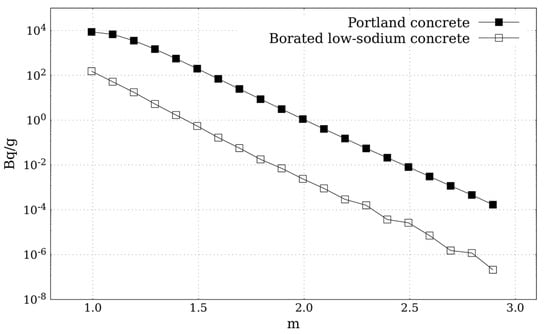
Figure 8.
Decline in 24Na specific activity in Portland concrete and borated low-sodium concrete throughout the top shielding.
Since the dose rate limit on the top of the experimental terminal is relatively low, the use of homogeneous shielding may result in the specification for a thicker terminal roof. Alternatively, a combination of different shielding materials can be used to improve the shielding efficiency. The USRBIN card in FLUKA was utilized to score the average ambient dose equivalent rates for five different testing combinations, as shown in Figure 9. Owing to Group 4’s large volume of dense concrete and its economic impact, the Group 5 solution was finally selected. As illustrated in Figure 10, the top shielding thickness of Group 5 was reduced by 1.1 m compared to Group 1, and the average ambient dose equivalent rate outside the top shielding was ~0.15 μSv/h.
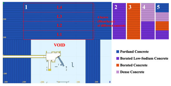
Figure 9.
Five combinations of shielding materials (Portland concrete, borated low-sodium concrete, borated concrete, and dense concrete) in the top shielding, which are filled from L1 to L4. Distances are given in cm.
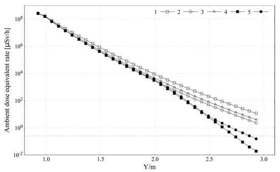
Figure 10.
Average dose rate attenuation in different configurations with the elevation of the top shielding. The bullets (1, 2, 3, 4, 5) correspond to the number of five different combinations of shielding materials illustrated in Figure 9.
3.2. Prompt Dose Rates
To assess if the shielding design meets the dose rate limits during irradiation, the USRBIN card was used to score the ambient dose equivalent rate inside and outside the experimental terminal when a 12 kW proton beam bombards the 100Mo target. As shown in different sections of the dose rate’s 3D distribution (Figure 11), the ambient dose equivalent rate is the highest near the beam spot, which is 2.6 × 10⁵ Sv/h and decreases to 100 Sv/h at the inner wall. With the shielding layout, the dose rates outside and above the terminal are about 0.1 μSv/h, thus meeting the dose rate limit requirements.
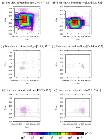
Figure 11.
Prompt ambient dose equivalent rate distribution (μSv/h) in the target terminal.
The exposure dose rates of the workers in NINE regions of interest during irradiation were also scored. The regions were arranged 1 m from the outer shielding wall with the size of 30 cm (width) × 60 cm (length) × 170 cm (height), whose positions are illustrated in Figure 12. The average ambient dose equivalent rates of these regions are less than 0.15 μSv/h.
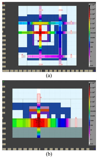
Figure 12.
Location and ambient dose equivalent rate distributions (μSv/h) in the regions of interest. (a) Top view at beamline level, (b) Side view at beamline level. The materials are indicated by different colors corresponding to Figure 4. Distances are given in cm.
In this work, a 3D visualization method of the FLUKA’s radiation fields was developed as a supplement to the built-in visualization function of Flair, as detailed in Figure 13. It is mainly based on data-processing scripts and ParaView. ParaView is an open-source tool supported by Visualization Toolkit and the Qt cross-platform application framework []. The raw simulation data from FLUKA can be processed and imported into ParaView and overlaid with the geometry model in STL. Customized data processing and visualization functions can be added through plug-ins (e.g., Calculator, Contour, Clip, and Delaunay3D). With this method, the 3D radiation field can be displayed interactively and intuitively, making it suitable for presentation and demonstrations.
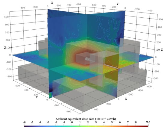
Figure 13.
Visualization of FLUKA 3D radiation field simulation data based on ParaView.
3.3. Residual Radioactivity Studies
Secondary particles generated during the irradiation lead to the activation of various components of the target system and the shielding concrete.
The USRBIN card in FLUKA was used to score the residual dose rate distribution inside the terminal immediately post-EOB and up to 30 days afterward. As illustrated in Figure 14, the ambient dose equivalent rate is the highest near the target, greater than 0.1 Sv/h at 0 s post-EOB. The dose rate level gradually declines through time. The average dose equivalent rate in a region with a size 30 cm × 60 cm × 170 cm at a distance of 1 m from the center of the target surface was scored. The value drops to ~96 μSv/h at 64 h after EOB, which is lower than the limit.
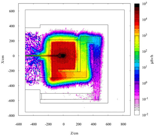
Figure 14.
Induced ambient dose equivalent rate (μSv/h) at beamline level (y = [−4.7, 1.6]) at 0 s post-EOB.
The specific activity of residual nuclides in different components of the target system and the inner shielding concrete after the irradiation was tallied with the RESNUCLEi estimators. It was found that the vacuum chamber (SS316L) features the largest inventory and the highest specific activity, even after a 30 day cooling time; hence, it is the main radiation source at EOB. The residual nuclides found to be critical in the vacuum chamber at 30 days post-EOB are 58Co (T1/2 = 70.82 d) 434.49 Bq/g, 51Cr (T1/2 = 27.702 d) 176.01 Bq/g, 54Mn (T1/2 = 312.12 d) 37.47 Bq/g, 56Co (T1/2 = 77.27 d) 30.64 Bq/g, and 55Fe (T1/2 = 2.73 y) 18.69 Bq/g.
3.4. Partial Shielding of Electrical Actuator
In the target system, the main electrical actuator is realized by dual stepper motor sets, an active one and a backup. Each set of stepping motors contains two symmetrically arranged two-phase stepping motors, which respectively drive the mechanical arm to rotate and lift. The straight-line distance between the motor and the center of the target is ~50 cm. The active and standby motors on the same side are connected by a dual-input speed reducer, which is connected to the revolution axis through a coupling. The schematic diagram is illustrated in Figure 15.
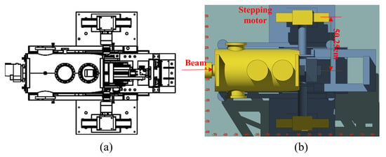
Figure 15.
(a) Two-dimensional diagram of the motor region, (b) motor region geometry in Flair. Distances are given in cm.
The winding insulation materials and semiconductor devices in stepper motors are demonstrated to be susceptible to ionizing radiation damage. For organic insulating materials, chemical reactions can occur when irradiated, affecting the mechanical and insulating properties []. Ionization and displacement damage also occur inside semiconductor materials when irradiated, changing the microstructure of the material, affecting its overall performance [,]. Therefore, partial shielding was designed to prevent the short-term failure of the stepper motor components in the intense radiation field. Taking into account the load bearing of the motor support and the low cost, an iron alloy (Q235A) was selected to shield secondary radiation.
Because the internal structure of stepping motors is very complex, the motor and the reducer models were simplified, the size of the motors is 8.58 cm × 8.58 cm × 15.6 cm, and the material is iron. The sidewall thickness of the shielding hoods is 0.8 cm and the material is Q235A. The top shielding consists of eight detachable plates, each with a thickness of 1 cm, for ease of installation purposes.
The USRBIN card was used to score the variation in the absorbed dose rate of the motor region with 8 cm shielding plates. The prompt absorbed dose rate of the motor region is ~2.5 Gy/h, a drop of about 63% compared to that without shielding (6.8 Gy/h). Thus, the maximum allowable exposure time increases by 2.7 times.
4. Conclusions
The availability of MC codes makes it convenient to study shielding issues of nuclear facilities before construction, especially concerning complex 3D geometry such as mazes and penetrations []. The construction of geometric and physical models plays a decisive role in the accuracy of the simulation results. In addition, appropriate variance reduction techniques and strategies can improve the work efficiency and statistics of the results.
In this work, the MC platform FLUKA was utilized to assess the RP problems of the target terminal for medical isotope production based on a superconducting proton linac and launch optimizations. A combination of different shielding materials was used, weighing economics and shielding effect; the top shielding thickness is 1.1 m thinner than using a homogenous material. In the case of a 12 kW proton beam impinging on the 100Mo target, the prompt ambient dose equivalent rates outside the target terminal meet the institute’s RP policy. The dose rates inside the terminal drop below 100 μSv/h at 64 h past EOB; the target chamber made of SS316L is the main source term at this time. The expected service lives of the main electrical actuators in this target system can be effectively extended by 2.7 times with partial shielding.
The calculation results can be used for environmental impact assessment. If the construction plan changes later, the simulation strategy weighing the accuracy of simulation results and the project’s progress, together with the 3D visualization method of radiation fields utilized in this work, can still serve in further research and design.
Author Contributions
Methodology, Z.L.; Software, Y.L.; Formal analysis, D.C.; Investigation, J.R. and K.Y.; Resources, H.J. and C.Y.; Writing—original draft, D.C.; Writing—review & editing, R.d.S.A.; Supervision, J.L. and Z.L.; Funding acquisition, Z.Q. All authors have read and agreed to the published version of the manuscript.
Funding
This research was funded by the National natural Science Foundation of China, grant number 11975115; Special Projects of the Central Government in Guidance of Local Science and Technology Development, grant number YDZX20216200001297; the Research and Development of Medical Isotopes based on High-current Superconducting Linear Accelerator Project; the Science and Technology Planning Project of Gansu, grant number 20JR10RA645; Lanzhou University Talent Cooperation Research Funds sponsored by both Lanzhou City, grant number 561121203 and Gansu provincial science and technology plan projects for talents, grant number 054000029.
Institutional Review Board Statement
Not applicable.
Informed Consent Statement
Not applicable.
Data Availability Statement
The data presented in this study are available on reasonable request from the corresponding author.
Conflicts of Interest
The authors declare no conflict of interest.
Appendix A

Table A1.
Mass fraction of different shielding materials in the simulation.
Table A1.
Mass fraction of different shielding materials in the simulation.
| Element | Portland Concrete (ρ = 2.3 g/cm3) | Borated Low-Sodium Concrete (ρ = 2.35 g/cm3) | Dense Concrete (ρ = 5.05 g/cm3) |
|---|---|---|---|
| Hydrogen | 1 × 10⁻² | 1 × 10⁻² | 2.8 × 10⁻³ |
| Carbon | 1 × 10⁻³ | 7.88 × 10⁻² | 2.8 × 10⁻³ |
| Oxygen | 5.29107 × 10⁻¹ | 4.934 × 10⁻¹ | 1.79 × 10⁻¹⁰ |
| Sodium | 1.6 × 10⁻² | 2 × 10⁻³ | 2 × 10⁻³ |
| Magnesium | 2 × 10⁻³ | 1.11 × 10⁻² | 9 × 10⁻⁴ |
| Aluminum | 3.3872 × 10⁻² | 1.8 × 10⁻² | 5 × 10⁻³ |
| Silicon | 3.37021 × 10⁻¹ | 1.0105 × 10⁻¹ | 1.57 × 10⁻² |
| Potassium | 1.3 × 10⁻² | 1.65 × 10⁻³ | 3 × 10⁻⁴ |
| Calcium | 4.4 × 10⁻² | 2.685 × 10⁻¹ | 5 × 10⁻² |
| Iron | 1.4 × 10⁻² | 8.3 × 10⁻³ | 7.408 × 10⁻¹ |
| Manganese | - | 1.3 × 10⁻⁷ | 1 × 10⁻³ |
| Phosphorus | - | 2.4 × 10⁻⁶ | - |
| Titanium | - | 9.2 × 10⁻⁴ | - |
| Barium | - | 1.2 × 10⁻⁴ | - |
| Chromium | - | 1.2 × 10⁻⁵ | - |
| Copper | - | 3.85 × 10⁻⁵ | - |
| Zinc | - | 8.35 × 10⁻⁵ | - |
| Scandium | - | 4.65 × 10⁻⁶ | - |
| Cesium | - | 2.65 × 10⁻⁷ | - |
| Zirconium | - | 3.37 × 10⁻⁵ | - |
| Sulfur | - | 4.55 × 10⁻³ | 1.8 × 10⁻³ |
| Cobalt | - | 3.4 × 10⁻⁶ | - |
| Europium | - | 3.35 × 10⁻⁷ | - |
| Boron | - | 2 × 10⁻³ | - |
References
- Radioisotopes in Medicine. Available online: https://www.world-nuclear.org/information-library/non-power-nuclear-applications/radioisotopes-research/radioisotopes-in-medicine.aspx (accessed on 2 March 2022).
- Ruth, T. Accelerating production of medical isotopes. Nature 2009, 457, 536–537. [Google Scholar] [CrossRef] [PubMed]
- Huang, W.; Liang, J.X.; Wu, Y.X.; Wu, J.W.; Luo, Z.F. Development of radioisotopes preparation technology in China. J. Isot. 2019, 32, 208–217. [Google Scholar] [CrossRef]
- National Academies of Sciences, Engineering, and Medicine. Molybdenum-99 for Medical Imaging; The National Academies Press: Washington, DC, USA, 2016; pp. 51–86. [Google Scholar] [CrossRef]
- Organization for Economic Cooperation and Development/Nuclear Energy Agency. The Supply of Medical Radioisotopes: An Economic Diagnosis and Possible Solutions; OECD Publishing: Paris, France, 2019; pp. 78–94. [Google Scholar] [CrossRef]
- Pitas, K.; Piefer, G. SHINE technology and progress toward US-based molybdenum-99 production. J. Nucl. Med. 2015, 56, 165. [Google Scholar]
- Hoehr, C.; Bénard, F.; Buckley, K.; Crawford, J.; Gottberg, A.; Hanemaayer, V.; Kunz, P.; Ladouceur, K.; Radchenko, V.; Ramogida, C.; et al. Medical isotope production at TRIUMF–from imaging to treatment. Phys. Procedia 2017, 90, 200–208. [Google Scholar] [CrossRef]
- Canadian Light Source Inc. Production of Molybdenum-99 Using Electron Beams. U.S. Patent US20140348284A1, 27 November 2014. Available online: https://patents.google.com/patent/US20140348284A1/en (accessed on 5 November 2021).
- Liu, Z.; Trudel, A.; Augusto, R.S.; Buckley, K. Shielding assessment of the IAMI facility. Radiat. Phys. Chem. 2020, 177, 109154. [Google Scholar] [CrossRef]
- Celler, A.; Hou, X.; Bénard, F.; Ruth, T. Theoretical modeling of yields for proton-induced reactions on natural and enriched molybdenum targets. Phys. Med. Biol. 2011, 56, 5469. [Google Scholar] [CrossRef] [PubMed]
- Liu, S.H.; Wang, Z.J.; Jia, H.; He, Y.; Dou, W.P.; Qin, Y.S.; Chen, W.L.; Yan, F. Physicsdesign of the CIADS 25 MeV demo facility. Nucl. Instrum. Methods. Phys. Res. A 2017, 843, 11–17. [Google Scholar] [CrossRef]
- Burgerjon, J.J.; Gelbart, Z.; Hendry, G.O.; Lofvendahl, J.C.; Mcilwraith, L.; Pinto, G.A. A high-power target system for radioisotope production. In Proceedings of the Eleventh International Conference on Cyclotrons and their Applications, Tokyo, Japan, 13–17 October 1986. [Google Scholar]
- Chen, D.Y. Development of Target System for Medical Isotope Tc-99m Production Based on the Superconducting Linac. Master’s Thesis, Lanzhou University, Lanzhou, China, 16 May 2022. [Google Scholar]
- ICRP. Recommendations of the ICRP. ICRP Publication 26. Annals of the ICRP; Pergamon Press: Osaka, Japan, 1977; pp. 1–53. Available online: https://www.icrp.org/publication.asp?id=ICRP%20Publication%2026 (accessed on 6 December 2021).
- National Standard of the People’s Republic of China. Basic Standards for Protection Against Ionizing Radiation and for the Safety of Radiation Sources, GB 18871-2002. 2002. Available online: http://www.nirp.cn/userfiles/file/GB18871-2002.pdf (accessed on 6 December 2021).
- Battistoni, G.; Boehlen, T.; Cerutti, F.; Chin, P.W.; Esposito, L.S.; Fassò, A.; Ferrari, A.; Lechner, A.; Empl, A.; Mairani, A.; et al. Overview of the FLUKA code. Ann. Nucl. Energy 2015, 82, 10–18. [Google Scholar] [CrossRef]
- Battistoni, G.; Gadioli, E.; Brugger, M.; Ferrari, A.; Smirnov, G.; Vlachoudis, V.; Muraro, S.; Empl, A.; Villari, R.; Carboni, M.; et al. The application of the Monte Carlo code FLUKA in radiation protection studies for the large hadron collider. Prog. Nucl. Sci. Techol. 2011, 2, 358–364. [Google Scholar] [CrossRef]
- Vlachoudis, V. FLAIR: A Powerful but User Friendly Graphical Interface For FLUKA. In Proceedings of the International Conference on Mathematics, Computational Methods & Reactor Physics, Saratoga Springs, NY, USA, 3–7 May 2009. [Google Scholar]
- Augusto, R.S.; Trudel, A.; Liu, Z.; Kinakin, M.; Paley, W.; Bjelić, Z.; Messenberg, A.; Mildenberger, J.; Chak, J.; Groumoutis, T.; et al. An overview of the shielding optimization studies for the TRIUMF-ARIEL facility. Nucl. Instrum. Methods. Phys. Res. A 2021, 1005, 165401. [Google Scholar] [CrossRef]
- Butler, H.M.; Wallace, K.M.; Fulmer, C.B. Half-value thickness measurements of ordinary concrete for neutrons from cyclotron targets. Am. Ind. Hyg. Assoc. J. 1974, 35, 234–237. [Google Scholar] [CrossRef] [PubMed]
- The Catalyst User’s Guide v2.0 ParaView 4.3.1. Available online: https://www.kitware.com/paraview-catalyst-users-guide-v2-0-available/ (accessed on 1 May 2022).
- Ferry, M.; Ngono, Y. Energy transfer in polymers submitted to ionizing radiation: A review. Radiat. Phys. Chem. 2021, 180, 109320. [Google Scholar] [CrossRef]
- Brews, J.R.; Allenspach, M.; Schrimpf, R.D.; Galloway, K.F.; Titus, J.L.; Wheatley, C.F. A conceptual model of a single-event gate-rupture in power MOSFETs. IEEE Trans. Nucl. Sci. 1993, 40, 1959–1966. [Google Scholar] [CrossRef]
- Hefner, A.R.; Blackburn, D.L.; Galloway, K.F. The effect of neutrons on the characteristics of the insulated gate bipolar transistor (IGBT). IEEE Trans. Nucl. Sci. 1986, 33, 1428–1434. [Google Scholar] [CrossRef]
- Infantino, A.; Cicoria, G.; Lucconi, G.; Pancaldi, D.; Vichi, S.; Zagni, F.; Mostacci, D.; Marengo, M. Radiation Protection studies for medical particle accelerators using FLUKA MonteCarlo Code. Radiat. Prot. Dosim. 2017, 173, 185–191. [Google Scholar] [CrossRef] [PubMed]
Disclaimer/Publisher’s Note: The statements, opinions and data contained in all publications are solely those of the individual author(s) and contributor(s) and not of MDPI and/or the editor(s). MDPI and/or the editor(s) disclaim responsibility for any injury to people or property resulting from any ideas, methods, instructions or products referred to in the content. |
© 2023 by the authors. Licensee MDPI, Basel, Switzerland. This article is an open access article distributed under the terms and conditions of the Creative Commons Attribution (CC BY) license (https://creativecommons.org/licenses/by/4.0/).