Abstract
Submerged inlet has been widely used in UAVs and cruise missiles due to its good stealth characteristics, but it also brings the disadvantage of poor aerodynamic characteristics. Especially in large maneuvering flight, the flow field near the fuselage has a strong unsteady effect, and the total pressure recovery coefficient and distortion characteristics have deteriorated sharply. In order to investigate the steady and transient aerodynamic characteristics of the submerged inlet in large maneuver flight and improve its maneuver envelope, a design scheme of a distributed submerged inlet for large maneuver flight is proposed in this paper. Taking a cruise missile as the research object, the steady and transient analysis of the conventional submerged inlet and the distributed submerged inlet is carried out using CFD numerical method. The results show that the distributed submerged inlet can significantly improve the inlet performance and enhance the sideslip limit of the submerged inlet during large sideslip maneuver flight. When the sideslip angle is 30°, compared with the conventional submerged inlet configuration, the outlet total pressure recovery coefficient of the distributed submerged inlet configuration is increased by 44.2%, and the total pressure distortion index is reduced by 66.3%.
1. Introduction
The 4S standards of the fourth-generation fighter (called the fifth generation by Russia) refer to Stealth, Supersonic, Super sensor, and Super mobility. Among them, super maneuverability refers to the ability of aircraft to significantly change its flight speed, flight altitude, and flight direction within a certain period of time. It is an important tactical and technical indicator of aircraft. The excellent maneuverability is conducive to the advantages of the fighter in close combat and breaking through the flight-restricted area, so the maneuverability is very important for the fighter. In order to achieve large maneuver flight, it is necessary to consider not only aerodynamic layout design and aerodynamic configuration design, but also excellent inlet and engine matching. When the aircraft maneuvers rapidly, strong unsteady effects appear in the fuselage flow field, such as the flow parameters at the inlet, the total pressure recovery coefficient at the outlet, and the total pressure distortion. Especially in the maneuvering state of high angle of attack and high sideslip angle, the inlet distortion characteristics deteriorate rapidly, which can very easily to cause engine surge or even engine shutdown and poses a serious threat to flight safety. Therefore, if the aircraft wants to obtain excellent maneuverability, it is necessary to find out the aerodynamic characteristics of the inlet during maneuvers at high angles of attack and high sideslip angles. Common maneuvers include circling, rolling, diving, somersault, battle turning, and rapid ascent. These maneuvers are characterized by large changes in flight angle of attack/sideslip angle, large three-axis angular rate, and large changes in velocity/direction/altitude. At the same time, there are strong unsteady characteristics in the internal flow of the inlet that pose a great challenge to theoretical research, computational simulation, test technology, verification means, etc.
Walsh K R et al. used experimental and numerical simulation methods to study the influence of the high angle of attack maneuver flight on the aerodynamic characteristics of the inlet. The research results showed that the increase of the angle of attack from 10° to 60° would lead to an increase in the range of low-pressure area at the inner side of the inlet bottom and showed a more obvious pressure gradient on the engine inlet section [1]. In the F/A-18A project, SMITH CF et al. carried out a numerical simulation of an aircraft inlet under multiple working conditions in order to explore the difference in inlet aerodynamic characteristics between rapid maneuver flight and steady flight. The research results show that the static pressure in the numerical calculation results is in good agreement with the flight data [2]. In order to judge whether the results obtained under stable conditions are sufficient to describe the distortion level generated by the inlet during the rapid maneuver of the aircraft, Yuhas A J used experimental means to study the aerodynamic characteristics of the inlet. The research results show that the transient high angle of attack maneuver conditions will not improve the distortion of the inlet [3]. Steenken W G compared the steady inlet data with the inlet data during the transient rapid maneuver, and the results showed that the total pressure recovery of the rapid maneuver inlet was very consistent with the total pressure recovery coefficient obtained under the equivalent stable angle of attack [4]. In order to explore whether the inlet can provide stable and uniform airflow for the engine during flight outside the normal maneuvering envelope, Steenken W G et al. used wind tunnel experiments to explore the inlet during maneuvering flight. In the experiments, engine surges were encountered in the process of nose left deviation and nose right deviation, while the total pressure distortion level did not exceed the maximum limit during the stable attitude experiment, which indicates that the aircraft’s position. The rapid change of attitude may cause the increase of total pressure distortion in the inlet and even cause engine surge [5]. In order to predict the total pressure recovery and distortion at the engine inlet section, PODLESKI used the numerical simulation method to study the forebody/inlet model of F/a-18 at = 0.20, = 60° and = 10°. The research results show that the calculation program used in the article tends to underestimate the total pressure recovery at the engine inlet section and overestimate the distortion level [6]. In order to accurately predict the performance of aircraft inlet under extreme flight conditions, Bruns J E et al. used numerical simulation methods to explore the inlet. The results showed that the calculated results were in good agreement with the surface static pressure of the precursor in the wind tunnel test results, and the calculated results were slightly lower than the experimental data. This difference may be partly due to the low mesh resolution at the inlet lip [7]. Wu Chaojun and others developed a maneuvering inlet test device based on dual torque motor synchronous drive, simulated the rapid pitching and other maneuvering processes of the fighter and different working conditions of the inlet, and established the unsteady test method of the fighter inlet. The basic law of inlet performance change during a fast pitch maneuver of a fighter model is studied by means of the test [8]. Yang Yingkai conducted a wind tunnel test study on the dynamic characteristics of the bump inlet on both sides and explored the aerodynamic characteristics of the inlet within a certain angle of attack. The research results show that the total pressure recovery coefficient and distortion index have a strong unsteady hysteresis effect, which is significantly different from the steady-state results at the same angle of attack [9]. Xiang Huan et al. applied the dynamic nested mesh technology to study the dynamic aerodynamic characteristics of the fighter’s inlet under a rapid pitch maneuver and verified it with flight data. They captured the unsteady hysteresis effect in the inlet during the fighter’s maneuver flight and analyzed its influencing factors and mechanism [10,11,12,13]. However, most of the current research on the unsteady flow characteristics in the inlet during maneuvering flight is carried out for the conventional inlet with a windward surface, and it is difficult to find the relevant information of the submerged inlet in the domestic and foreign open literature.
The design of the submerged inlet integrated with the aircraft body has many advantages. In addition to significantly reducing the windward surface of the aircraft and reducing the wind resistance, it can also reduce the radar scattering area and improve the survivability of the aircraft [14,15,16,17]. At present, the submerged inlet is widely used in cruise missiles and UAVs, such as the cruise missile AGM-129 and the whaling fork of the United States [18,19]. Researchers from various countries have also carried out a series of research on the submerged inlet. As early as 1945, Axelson J A et al. designed a NACA submerged inlet and carried out a lot of experiments on it. The submerged inlet uses a long inclined plate with a very small angle of inclination (about 7°) to introduce air into the inlet, but the intake volume of the inlet is small and the total pressure recovery coefficient is low [20,21,22,23,24,25]. Subsequently, a large number of researchers carried out in-depth research on the intake mechanism [26,27], optimization design method [28,29,30], internal flow characteristics [31,32,33], and flow control method [34,35,36,37] of the submerged inlet. Now the performance of the submerged inlet can basically meet the engineering application requirements. However, the research on the submerged inlet is only limited to the steady numerical simulation or ground wind tunnel experiment when the angle of attack and sideslip of the aircraft are constant. The research on the unsteady flow characteristics of the submerged inlet in the process of large maneuvering flight is still blank, and the research on the optimization and flow control method of the submerged inlet in the process of large maneuvering flight is impossible.
In this paper, a new configuration of the submerged inlet based on the distributed design concept is proposed creatively to solve the problem of the low efficiency of submerged inlets during flight in a large maneuver state. Taking a cruise missile as the research object, the CFD numerical method is used to analyze the steady flow characteristics of the conventional submerged inlet and the distributed submerged inlet under the condition of stable aerodynamic angle, and then the transient flow characteristics during the large maneuver flight are analyzed. The unsteady aerodynamic characteristics of the distributed submerged inlet and the conventional submerged inlet during the large maneuver movement are compared to improve their adaptability in the large maneuver flight.
2. Distributed Submerged Inlet Design
2.1. Flow Characteristics Analysis of Submerged Inlet
In order to avoid the engine surge or even engine shutdown caused by the sharp deterioration of the inlet distortion characteristics of the submerged inlet at high angle of attack and large sideslip angle maneuver, it is necessary to discuss the intake mechanism of the submerged inlet under different flight conditions. Figure 1 is a schematic diagram of the mechanism of submerged air intake under different flight conditions. From Figure 1a, it can be seen that when the angle of attack and the sideslip angle are small, the external airflow is mainly driven into the inlet by the entrainment vortices generated by the side edge. As the sideslip angle gradually increases, the side edge with the same direction of the incoming flow can no longer produce a suction vortex that is beneficial to the intake. Although the side edge opposite to the incoming flow can still produce a suction vortex that is beneficial to the intake, the effect of driving the external airflow into the inlet is weakened a lot because the airflow changes the angle of the side edge during the flow around the body, as shown in Figure 1b.
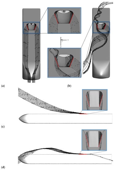
Figure 1.
Intake mechanism intention of submerged inlet under different flight conditions.((a) Intake mechanism intention when sideslip angle and angle of attack are small, (b) Intake mechanism intention when sideslip angle is large and angle of attack is small, (c) Intake mechanism intention when the sideslip angle is small and the angle of attack is positive and large, (d) Intake mechanism intention when sideslip angle is small, angle of attack is negative and large).
It can be seen from Figure 1c that the submerged inlet has a windward surface during the flight at a positive angle of attack, which is conducive to improving the inlet efficiency, and the airflow directly flows into the inlet, which experiences less drag from the boundary layer on the surface of the projectile, and the total pressure loss of the airflow is less. It can be seen from Figure 1d that the submerged inlet also has a windward surface during the flight with a negative angle of attack, which is beneficial to improve the intake efficiency, but there is certain energy loss when the airflow is dragged by the boundary layer on the surface of the projectile when it bypasses the surface of the projectile. At the same time, the angle of airflow around the body changes, so the effect of driving the external airflow into the inlet is somewhat weakened.
From the above analysis, it can be seen that the inlet efficiency of the submerged inlet is low when the sideslip angle and attack angle are large, and some flow control measures should be adopted to improve its inlet performance. However, the use of commonly used passive flow control methods, such as ridge vortex generators, will increase the projected area of the incoming flow direction and increase the resistance while destroying the stealth performance. If the commonly used active flow control methods, such as jet, blowing, and suction flow control methods, are used, they will need to consume additional mass and energy, and need an external drainage pump and other equipment, which is more complex. Therefore, according to the characteristics of the submerged inlet and the characteristics of the large sideslip maneuver flight, the distributed submerged inlet configuration applied to the large maneuver state is proposed in this paper.
2.2. Distributed Submerged Inlet Design
The inlet efficiency of the submerged inlet is high when there is a windward surface, so an inlet layout that will produce an additional windward surface in the flight state of a large sideslip maneuver is designed. Its three views and main parameters are shown in Figure 2. A submerged inlet, called auxiliary inlet, is arranged on both sides of the submerged inlet. The submerged auxiliary inlet is connected with the main inlet, and its main function is to create an additional windward surface for the inlet during sideslip maneuver, so as to improve the low intake efficiency of the conventional submerged inlet during a large sideslip maneuver. The auxiliary inlet is designed according to the design method of submerged inlet, and then the designed auxiliary inlet and main inlet are trimmed and the intersection line is smoothed. In Figure 2, gray is the part that needs to be retained after the trim of the distributed inlet, and yellow is the part that needs to be deleted after the trim.
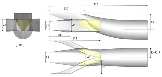
Figure 2.
Three views and main parameters of the distributed submerged inlet.
The main research object of this paper is the conventional submerged inlet configuration and the distributed inlet configuration with additional auxiliary inlets on both sides of the body. For ease of reading, the former is referred to as the conventional submerged inlet configuration, and the latter is referred to as the distributed inlet configuration. The conventional submerged inlet configuration, the distributed inlet configuration, and the projectile body are shown in Figure 3. The cross-section shape of the projectile body is a filleted rectangular shape. The inlet opening is located on the lower belly plane of the missile body, and the upper and lower surfaces of the missile body are inverted for easy observation (the upper and lower surfaces are inverted in the subsequent relevant pictures).
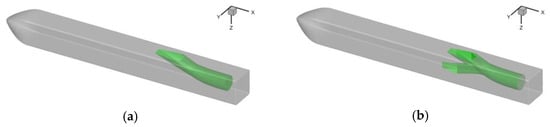
Figure 3.
Two configurations of inlet and missile body. ((a) Conventional inlet configuration, (b) Distributed inlet configuration).
3. Calculation Mesh and Boundary Condition Setting
3.1. Steady-State Mesh and Boundary Condition Setting
Figure 4 shows the surface mesh of the missile, inlet, and far field. The mesh form adopts unstructured polyhedral mesh. The far-field calculation domain of the conventional submerged inlet configuration and the distributed submerged inlet configuration are identical. Both are cuboids with length, width, and height of 40 m, 10 m, and 10 m respectively. The two configurations of the inlet and the body model body surface mesh size are the same. The minimum size of the body surface mesh is 1 mm and the maximum size is 5 mm; the minimum size of the inlet surface mesh is 1 mm, the maximum size is 3 mm.
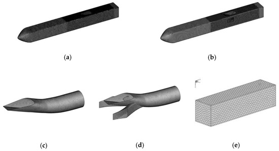
Figure 4.
Surface mesh of projectile body, inlet, and far-field. ((a) Surface mesh of missile body in the conventional inlet, (b) Surface mesh of missile body in the distributed inlet, (c) Surface mesh of the conventional inlet, (d) Surface mesh of the distributed inlet, (e) Surface mesh of far-field).
The Spalart–Allmaras turbulence model is mainly used in the numerical simulation in this paper. The S-A turbulence model is a single equation model, which can directly solve the modified turbulent viscosity. It is often used in the flow around the aviation field and is characterized by high accuracy and small amount of calculation. In order to capture the complex flow on the surface of the missile and inlet as well as possible, enhanced wall treatment (EWT) is required, which requires that the near-wall mesh is very dense, and y+ is close to 1. However, considering that too dense near-wall mesh will lead to low mesh quality, the boundary layer mesh shall be properly adjusted without reducing the calculation accuracy. The final number of boundary layers is 10, the first layer of mesh height is 0.01 mm, and the growth rate is 1.2. In order to make the calculation results more accurate and reliable, an encryption area is set around the missile body, the maximum size of the encryption area is not more than 30 mm, and an encryption area is also set near the inlet, the maximum size of the encryption area is not more than 3 mm, as shown in Figure 5. The number of volume mesh of the conventional submerged inlet configuration is about 0.9 million, of which the boundary layer prismatic mesh accounts for 0.4 million and the polyhedral mesh away from the wall accounts for 0.5 million. The number of the distributed inlet configuration volume mesh is about 1.2 million, of which the boundary layer prismatic mesh accounts for 0.5 million and the polyhedral mesh away from the wall accounts for 0.7 million.
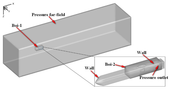
Figure 5.
Setting of Steady State Boundary Conditions.
Figure 5 shows the setting of steady-state boundary conditions. The pressure far-field boundary is used for the far-field, and the freestream parameters are given according to the atmospheric conditions at 5 km altitude, = 0.7; The outlet of the inlet adopts the pressure outlet boundary condition, and the pressure is set to the corresponding pressure when = 0.4; the body and inlet adopt non-slip adiabatic wall boundary.
3.2. Transient State Mesh and Boundary Condition Setting
In the transient calculation, the dynamic nested mesh technology is used to establish the calculation domain of two concentric spheres, which are the external flow field of the flight airspace and the internal flow field, including the aircraft. The external flow field domain is stationary during the simulation of large maneuvering flight, and the internal flow field mesh, including the aircraft body rotates around the center of gravity along with the aircraft. The mesh size of the body and inlet surface is consistent with that of the steady state. An encryption area shall be set near the inlet, and the maximum size of the encryption area shall not exceed 3 mm, as shown in Figure 6. The mesh boundary layer settings are consistent with the steady state. The number of volume meshes of the conventional submerged inlet configuration is about 1.4 million, of which the boundary layer prismatic meshes account for 0.8 million and the polyhedral mesh away from the wall accounts for 0.6 million; The number of the distributed inlet configuration volume meshes is about 1.6 million, of which the boundary layer prismatic meshes account for 0.9 million and the polyhedral meshes away from the wall account for 0.7 million.
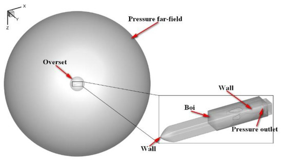
Figure 6.
Setting of Transient Boundary Conditions.
Figure 6 shows the setting of transient boundary conditions. The pressure far-field boundary is used for the far-field, and the free-flow parameters are given according to the atmospheric conditions at 5 km altitude, = 0.7; the outlet of the inlet adopts the pressure outlet boundary condition, and the pressure is set to the corresponding pressure when = 0.4; the interface between dynamic and static domains is set as the overset boundary condition; the body and inlet adopt non-slip adiabatic wall boundary.
3.3. Independence Analysis
3.3.1. Mesh Independence Analysis
The mesh-independence analysis takes the conventional submerged inlet as an example. In order to minimize the impact of the number of meshes on the accuracy of the results, four sets of mesh are finally obtained by adjusting the density of mesh nodes. The number of volume meshes is 0.9 million, 1.2 million, 3 million, and 5 million, respectively. The numerical simulation results and experimental results of four sets of mesh are shown in Table 1. Compared with the experimental results, the error of the calculated results is less than 0.65%, which indicates that the accuracy of the numerical solution of the flow field is basically independent of the number of meshes after the meshes are larger than 0.9 million. In order to save calculation time, this paper uses the node density of mesh scheme 1 to calculate.

Table 1.
Comparison of different mesh schemes and experimental results.
It should be noted that the computational mesh used in this paper is unstructured polyhedral mesh. At the same density, the number of polyhedral meshes is much lower than that of conventional unstructured tetrahedral mesh. Taking the polyhedral mesh with a mesh number of about 0.9 million as an example, using the same face mesh, the same boundary layer setting, and the same volume mesh growth rate, the total volume mesh number when dividing the tetrahedral mesh is about 3.7 million, of which the boundary layer prism mesh accounts for about 0.7 million, and the tetrahedral mesh far from the wall accounts for about 3 million. The geometry of the submerged inlet and projectile studied in [34,38] is similar to that in this paper. The number of calculation mesh is 0.9 million, so the calculation mesh used in this paper can meet the requirements of calculation accuracy.
3.3.2. Time Step Independence Analysis
The full name of the CFL condition is the Courant–Friedrich–Lewy condition. The CFL condition is an important parameter for the stability and convergence of numerical calculation, so it is a very important condition in computational fluid dynamics [39]. In the three-dimensional case, the CFL condition is:
In the formula, , , and are the velocities in the x, y, and z directions during the mesh movement; is the time step; , , and are the minimum mesh size of the calculation mesh in the x, y, and z directions. Generally, the value of is 1, which physically means that the displacement of fluid in unit time step cannot exceed the unit length of the calculation mesh, otherwise the calculation may diverge.
In this paper, two time steps of 0.001 s and 0.0001 s are selected for transient calculation, which can meet the CFL condition.
At the same time, in order to give consideration to the computational efficiency of the flow field simulation, two time steps of 0.001 s and 0.0001 s are used to analyze the step independence, taking the pitching maneuver of the conventional submerged inlet as an example. Let the mesh in the internal rotation domain conduct a simple pitching maneuver around the y-axis. The pitching angle changes in a sine motion. The average angular velocity of the sine motion is 60°/s and the amplitude is 30°.
Figure 7 shows the calculation results of the total pressure recovery coefficient at the outlet of the inlet under two time steps of 0.2 to 0.5 s. It can be seen from Figure 7 that the calculation results of the two step sizes are almost the same.
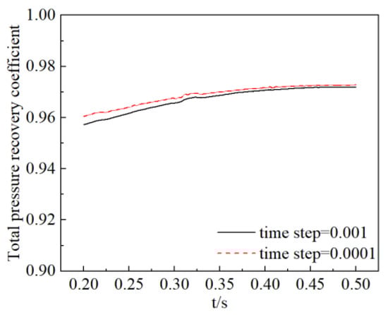
Figure 7.
Calculation results of total pressure recovery coefficient at outlet of the inlet in two time steps of 0.2 to 0.5 s.
The average total pressure recovery coefficient in 0.2~0.5 s is shown in Table 2. When the step length is 0.001 s, the average total pressure recovery coefficient during 0.2 to 0.5 s is 0.966. When the step length is 0.0001 s, the average total pressure recovery coefficient is 0.968 during 0.2 to 0.5 s. Based on the calculation result with a step of 0.0001 s, the error of the calculation result with a step of 0.001 s is only 0.2%, which means that a step of 0.001 s is sufficient to accurately capture the flow field details. Considering the computational efficiency and accuracy, the step size used in the transient calculation is 0.001 s.
Table 2.
Average total pressure recovery coefficient in 0.2~0.5 s.
3.4. Example Verification
In order to verify the accuracy of the numerical simulation method in this paper, the flow field of the missile body and the submerged inlet in the literature [40] was simulated and compared with the relevant experimental data. The calculation model is shown in Figure 8.
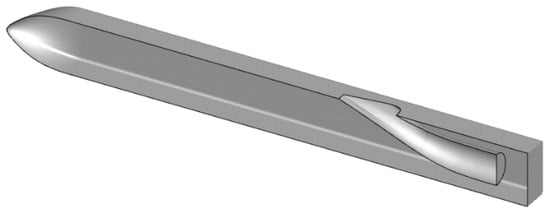
Figure 8.
Reference [40] Submerged inlet.
In the case of no sideslip, the flow field is symmetrical, so the half model is used for mesh generation to reduce the computational cost. Unstructured polyhedral mesh is adopted, and the far field is in the shape of a cuboid, with the length, width, and height of 40 m, 10 m, and 10 m, respectively. The local mesh of the missile body surface and inlet is shown in Figure 9. The total number of meshes in the computational domain is 0.5 million, the number of boundary layers is 10, the height of the first layer is 0.01 mm, and the growth rate is 1.2.
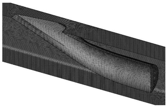
Figure 9.
Local mesh of missile body surface and inlet.
The calculation conditions are set according to the experimental conditions in the literature, = 0.73, and the altitude is 5 km. The pressure far-field boundary condition is adopted in the far field of the computational domain, and the outlet of the inlet is set as the pressure outlet. The inlet and missile body walls are set as non-sliding walls.
The experimental results show that of the missile body and the submerged inlet is 0.9220 when = 0.73 and = 0.4. In the calculation results, at the outlet of the inlet is 0.9244, and the error between the numerical simulation results and the experimental results is only 0.26%. Figure 10 shows the total pressure distribution at the outlet of the inlet, which is also in good agreement with the experimental results. Therefore, the accuracy of the numerical simulation method in this paper is verified.
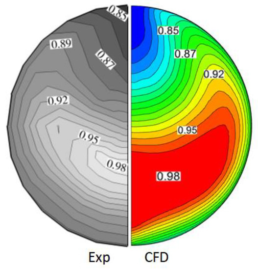
Figure 10.
Total pressure distribution at the outlet of the inlet.
4. The Flow Characteristics of Two Inlet Configurations under High Maneuver Condition
In order to simplify the problem, the change of inlet flow characteristics caused by the change of when = 0° and the change of inlet flow characteristics caused by the change of when = 0° are considered respectively in the calculation.
The total pressure recovery coefficient at outlet of the inlet and total pressure distortion index are commonly used to evaluate the inlet aerodynamic performance. This paper also uses the total pressure recovery coefficient and total pressure distortion index to evaluate the inlet performance.
The total pressure recovery coefficient is defined as the ratio of the average total pressure at the outlet of the inlet to the total pressure the of free flow, expressed as . The calculation formula is as follows:
In the formula, is the average total pressure at the section at the outlet of the inlet, and is the total pressure of freestream.
The total pressure distortion index is the main parameter used to evaluate the airflow uniformity at the outlet of the inlet, expressed as The calculation formula is as follows:
where is the maximum total pressure of the AIP section at the outlet of the inlet and is the minimum total pressure of the AIP section at the outlet of the inlet.
4.1. Analysis of Steady Flow Characteristics
During the steady state calculation, the attitude of the missile body and the incoming flow conditions remain unchanged. The total pressure recovery coefficient and total pressure distortion index on the outlet of the inlet section are shown in Figure 11. Configuration I represents the conventional submerged inlet, and configuration II represents the distributed inlet. It can be seen from Figure 11a,b that the of the two inlet configurations has a very similar trend with the . In the range of −30° to 30°, first rises, then decreases, and then rises. is above 0.88. The total pressure distortion indices of the two inlet configurations are also very similar with the angle of attack, showing a trend of first rising and then declining in the range of −30° to 30°, and the total pressure distortion indices are below 0.2. The of the conventional submerged inlet is slightly higher than that of the distributed inlet, and of the conventional submerged inlet is slightly lower than that of the distributed inlet. This is because there is a certain airflow mixing phenomenon at the intersection of the auxiliary inlet and the main inlet in the distributed submerged inlet configuration, which brings a certain energy loss. In addition, the auxiliary inlet located on both sides of the missile body in the distributed submerged inlet configuration will cause low-energy gas in the boundary layer on both sides of the missile body to flow into the inlet, which will also lead to a decrease in total pressure and an increase in total pressure distortion.
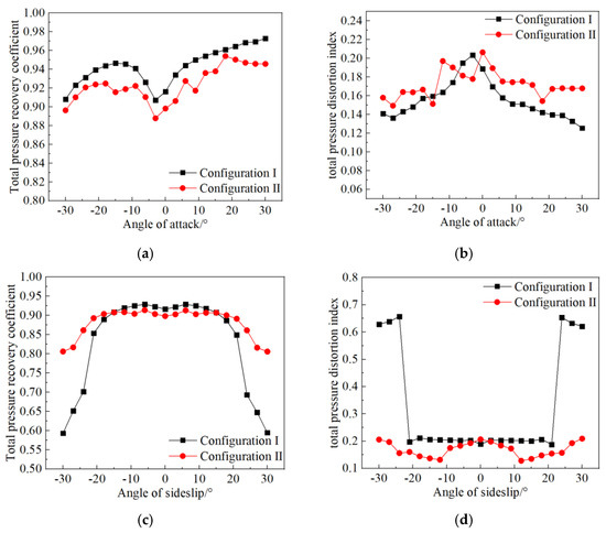
Figure 11.
Steady State Calculation Results. (a) Total pressure recovery coefficient versus angle of attack, (b) Total pressure distortion index versus angle of attack, (c) Total pressure recovery coefficient versus angle of sideslip, (d) Total pressure distortion index versus angle of sideslip.
It can be seen from Figure 11c,d that the limit of sideslip angle of conventional submerged inlet configuration is ±20°. When the absolute value of β is greater than 20°, at the outlet drops sharply; when reaches ± 30°, is less than 0.6. When is within ±20°, of the conventional submerged inlet is about 0.22, and when the reaches ±30°, the suddenly increases to 0.7. This is because the submerged inlet mainly relies on the entrainment vortices generated by the side edges to drive the external airflow into the inlet. When the absolute value of the is less than 20°, the side edges on both sides of the inlet can generate the entrainment vortices that are beneficial to the inlet to drive the external airflow into the inlet. When the absolute value of the is greater than 20°, the side edge with the same direction as the incoming flow can no longer generate the entrainment vortices beneficial to the air inlet. Although the side ribs opposite to the incoming flow can still produce entrainment vortices that are conducive to the intake, the effect of driving the external airflow into the inlet is greatly weakened because the airflow changes the angle of the airflow through the side ribs during the flow around the body.
When the is greater than ±20°, the at the outlet of the distributed submerged inlet also decreases to some extent, but the decrease is small. When reaches ±30°, the at the outlet of the distributed inlet is still greater than 0.80. of the distributed inlet is always kept within 0.2. When is ±10°, the is about 0.12. In the large sideslip flight state, compared with the conventional submerged inlet configuration, at the outlet of the distributed submerged inlet configuration is increased by 44.2%, and is reduced by 66.3%.
In order to better reveal the formation and development mechanism of flow in the submerged inlet under large sideslip condition, and Figure 12 lists the main flow characteristics in the inlet under typical sideslip angles. It can be seen from Figure 12a that when = −21°, the side edges on both sides of the inlet of the conventional submerged inlet can generate entrainment vortices. However, due to the different angles of the airflow passing through the side edges on both sides, the intensity of the entrainment vortices generated by the side edges with the same direction as the incoming flow is weak, and part of the airflow is not drawn into the inlet. With the further increase of , the intensity of the entrainment vortices generated by the side edges with the same direction of the incoming flow gradually weakens. It can be seen from the Figure 12b–d that when the absolute value of is greater than 24°, the entrainment vortices beneficial to the intake cannot be generated, and at the same time, there is obvious air separation. An obvious low total pressure area can be observed at the outlet of inlet. The area of the low total pressure area accounts for about one third of the total area. The same problem is also encountered at the side edges of the main inlet of the distributed inlet configuration. However, since the auxiliary inlets on both sides have a certain windward surface during sideslip maneuver flight, which can provide high energy airflow for the intake system to make up for the deficiencies of the inlet during large sideslip flight, no obvious low-pressure area is observed at the outlet of the inlet, and is above 0.8.
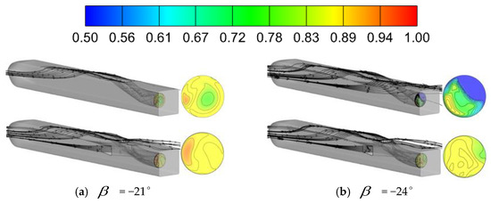
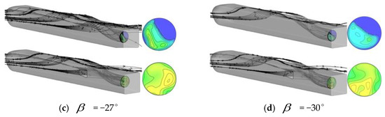
Figure 12.
Flow characteristics of inlet under typical sideslip angles.
4.2. Analysis of Transient Flow Characteristics
In order to simplify the problem, only the internal flow characteristics of the inlet during pitch maneuver and yaw maneuver are investigated [41,42,43]. In the course of pure pitch maneuver with constant incoming flow conditions, the angle of attack of the aircraft is equal to the angle of pitch; The angle of attack of the aircraft is equal to the sideslip angle during the simple yaw maneuver with the inflow conditions unchanged. In order to be consistent with the description in the steady-state analysis, the pitch angle in the periodic pitch maneuver is called the angle of attack, and the yaw angle in the periodic yaw maneuver is called the sideslip angle.
The background mesh remains stationary, and the given internal rotation domain mesh rotates along with the aircraft around the center of gravity in a single-axis, and the law is a sine function. In order to study the effect of pitch rate on the dynamic characteristics of the inlet, two motion laws shown in Figure 13 are applied to the mesh in the rotating domain. Due to the characteristics of the chord function, the angular velocity at different angles in the process of motion is different. The velocity is low near the peak or trough, and high away from the peak or trough. Therefore, the angular velocity marked in the figure is the average angular velocity.
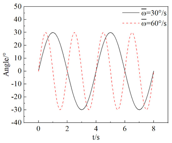
Figure 13.
Two Motion Laws of Transient Maneuver.
The two equations of motion law are:
4.2.1. Flow Characteristics of the Submerged Inlet with the Rapid Pitch Maneuver
Let the mesh in the internal rotating region conduct a simple pitching maneuver around the y-axis at two angular velocities, and the calculated total pressure recovery coefficient of the outlet of the inlet is shown in Figure 14.
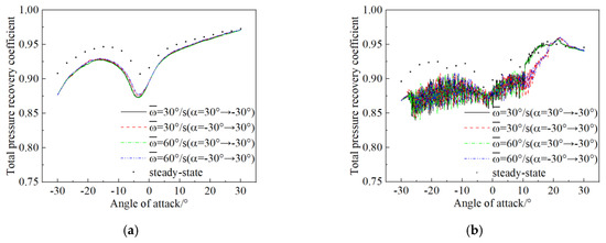
Figure 14.
Total pressure recovery coefficient versus angle of attack. (a) Conventional submerged inlet, (b) Distributed submerged inlet.
It can be seen from Figure 14 that the instantaneous total pressure recovery coefficient of two configurations of the inlet during pitching maneuver shows a trend of first increasing, then decreasing and then increasing with the increase of , which is consistent with the trend of equivalent steady state calculation results. However, the value of calculated in the steady state is slightly higher than that calculated in the transient state. When the = −30°, the difference between the results calculated in the steady state and the results calculated in the transient state is the largest, about 0.05. The difference decreases with the increase of . When reaches 30°, there is almost no difference between the steady-state and transient results.
It can be seen from Figure 14a that there is a certain hysteresis phenomenon in the pitching maneuver cycle. In the pitching up process (in the process of from −30° to 30°), the total pressure recovery coefficient is slightly lower than that in the pitching down process (in the process of from 30° to −30°), and the hysteresis phenomenon is obvious in the range of −10° to 0°.
It can be seen from Figure 14b that of the distributed inlet configuration fluctuates significantly during the pitching maneuver period. In the range of from 10° to 20°, it can be clearly observed that of the pitching up maneuver (in the process of from −30° to 30°) is significantly lower than that of pitching down maneuver (in the process of from 30° to −30°). This is because the submerged inlet is located in the belly of the missile, and the airflow has an upward velocity relative to the missile in the process of pitching down, which increases the included angle between the airflow and the plane where the submerged inlet opening is located, thus increasing the windward surface of the inlet to facilitate air intake. In contrast, the airflow has a downward velocity relative to the missile in the process of pitching up, which reduces the angle between the airflow and the plane of the submerged inlet opening, and thus reduces the windward surface of the inlet, which is not conducive to air intake.
The hysteresis of the conventional submerged inlet configuration is more obvious in the range of −10° to 0°, while the hysteresis of the distributed submerged inlet configuration is more obvious in the range of 10° to 20°. The reason for this difference is the different intake mechanism of the two configurations. Specifically, the conventional submerged inlet mainly relies on the suction vortex generated by the side edge at the inlet to drive the airflow into the inlet, so it is more sensitive to the angle between the airflow and the side edge when the airflow passes through the side edge. In addition to the entrained vortex generated by the side edges of the main inlet, the side edges of the auxiliary inlet distributed on both sides of the missile body are also generating entrained vortex beneficial to the intake. In the process of angle of attack change, the entrainment vortices intensity of the main inlet and the entrainment vortices intensity of the auxiliary inlet are not synchronized, so the angle of hysteresis of the two configurations is different.
4.2.2. Flow Characteristics of Submerged Inlet with Rapid Yaw Maneuver
Let the mesh in the internal rotating region perform a simple yaw maneuver around the z-axis at two angular velocities, and the calculated total pressure recovery coefficient of the outlet of the inlet plane is shown in Figure 15.
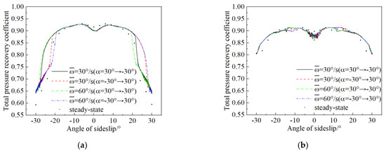
Figure 15.
Total pressure recovery coefficient versus angle of sideslip. (a) Conventional submerged inlet, (b) Distributed submerged inlet.
It can be seen from Figure 15 that in the range of from −30° to 30° during the yaw maneuver of the inlet of two configurations, the first increases, then decreases, then increases, and then decreases with the increase of , which is consistent with the trend of equivalent steady state calculation. When the absolute value of the is less than 20°, the transient and steady calculation results are almost consistent. When the is close to ±30°, the transient calculation result is slightly higher than the steady calculation result.
It can be seen from Figure 15a that the of the conventional submerged inlet drops sharply when the absolute value of is greater than 20°, and is less than 0.65 when the = ±30°. = 0° is considered as the equilibrium position. In the process of deviating from the equilibrium position, the is higher than that of approaching the equilibrium position. This phenomenon is particularly obvious in the range of −30° to −20° and 20° to 30°. This is due to the hysteresis effect of the flow field. Specifically, in the case of large sideslip flight, the side edge on the same side of the incoming flow can no longer produce entrainment vortices that are conducive to air intake, and the side edge on the opposite side of the incoming flow play a major role. In the process of deviating from the equilibrium position, the relative motion of the missile increases the angle between the airflow and the opposite side edge, thus increasing the intensity of the entrainment vortices, which is conducive to improving the intake efficiency. At the same time, it can be observed that the greater the angular velocity, the more obvious the hysteresis phenomenon.
From Figure 15b, it can be seen that the distributed submerged inlet configuration also has a significant decrease when the absolute value of the is greater than 20°, but the decrease is smaller than that of the conventional submerged inlet configuration. When the absolute value of the is 30°, is still greater than 0.8. This is because the special structure of the distributed submerged inlet creates additional intake conditions, so that it is no longer overly dependent on the entrainment vortices generated by the side edge to drive the external airflow into the inlet. There is an obvious hysteresis phenomenon near the sideslip angle of 12°. In the process of deviating from the equilibrium position, is higher than that near the equilibrium position. This is mainly because the auxiliary inlet on the opposite side of the incoming flow plays a major role in the large sideslip maneuver flight. In the process of deviating from the equilibrium position, the angle between the airflow and the inlet plane of the distributed inlet on the opposite side of the incoming flow is increased, which in turn increases the windward surface and leads to a higher total pressure recovery coefficient. At the same time, it can be observed that the greater the angular velocity, the more obvious the hysteresis phenomenon.
5. Conclusions
In this paper, based on the flow characteristics of the submerged inlet, the distributed submerged inlet configuration applied to the large maneuvering state is proposed. Firstly, the accuracy of the numerical simulation method is verified. Then, the flow characteristics of the conventional submerged inlet and the distributed submerged inlet are analyzed respectively in the steady and transient large maneuvering states, and the following conclusions can be obtained:
- The trend of transient and equivalent steady state calculation results of the two configurations of inlet during pitching maneuver is consistent, but the value of calculated in steady state is slightly higher than that calculated in transient state. When = −30°, the difference between the steady-state and transient results is the largest, which decreases with the increase of . When = 30°, there is almost no difference between the steady and transient results. In the course of the yaw maneuver, the trend of transient and equivalent steady state calculation results of is consistent, but the value of calculated in steady state is slightly lower than that calculated in transient state. When the absolute value of is less than 20°, the transient and steady calculation results are almost consistent. When is close to ±30°, the transient calculation result is slightly higher than the steady calculation result.
- When flying at a high angle of attack, the and of the distributed submerged inlet and conventional submerged inlet have little difference. Compared with the conventional submerged inlet configuration, at the outlet of the distributed submerged inlet configuration is increased by 44.2% and is reduced by 66.3% in the case of high sideslip flight, which greatly improves the performance of the inlet in the case of high sideslip maneuver flight, and significantly improves the sideslip limit of the submerged inlet.
- In the transient calculation results of the large maneuver flight state, the two submerged inlet configurations show an obvious hysteresis effect, which is more obvious with the increase of angular velocity.
Author Contributions
Conceptualization, J.Z.; methodology, J.Z.; software, J.Z.; validation, J.Z.; formal analysis, J.Z.; investigation, J.Z.; resources, J.Z.; data curation, J.Z.; writing—original draft preparation, J.Z.; writing—review and editing, B.M.; visualization, J.Z.; supervision, B.M.; project administration, B.M.; funding acquisition, B.M. All authors have read and agreed to the published version of the manuscript.
Funding
This research was funded by [the National Natural Science Foundation of China] grant number [12202363] and [the Natural Science Basic Research Program of Shaanxi] grant number [2021JQ-084].
Institutional Review Board Statement
Not applicable.
Informed Consent Statement
Not applicable.
Data Availability Statement
Not applicable.
Acknowledgments
Not applicable.
Conflicts of Interest
The authors declare no conflict of interest.
Nomenclature
| total pressure distortion index | |
| mass-average total pressure | |
| mass-average total pressure over the aerodynamic interface plane, Pa | |
| freestream total pressure, Pa | |
| maximum total pressure over the aerodynamic interface plane, Pa | |
| minimum total pressure over the aerodynamic interface plane, Pa | |
| Mach number | |
| Mach number at the exit | |
| freestream Mach number | |
| angle of attack, ° | |
| angle of sideslip, ° | |
| instantaneous angle in sinusoidal motion, ° | |
| instantaneous angular velocity in sinusoidal motion, °/s | |
| average angular velocity of sinusoidal motion, °/s | |
| Subscripts | |
| 0 | freestream |
| exit | |
| the aerodynamic interface plane | |
| maximum value on the aerodynamic interface plane | |
| minimum value on the aerodynamic interface plane | |
References
- Walsh, K.R.; Yuhas, A.J.; Williams, J.G.; Steenken, W.G. Inlet Distortion for an F/A-18A Aircraft during Steady Aerodynamic Conditions up to 60 Deg Angle of Attack; National Aeronautics and Space Administration, Dryden Flight Research Center: Edwards, CA, USA, 1997. [Google Scholar]
- Smith, C.F.; Podleski, S.D.; Barankiewicz, W.S.; Zeleznik, S.Z. Comparison of the F/A-18A inlet flow analysis with flight data. II. J. Aircr. 1996, 33, 457–462. [Google Scholar] [CrossRef]
- Yuhas, A.J.; Steenken, W.G.; Williams, J.G.; Walsh, K.R. F/A-18A Inlet Flow Characteristics During Maneuvers with Rapidly Changing Angle of Attack: NASA-TM-104327[R]; NASA: Washington, DC, USA, 1997.
- Steenken, W.G.; Williams, J.G.; Walsh, K.R. Inlet Flow Characteristics During Rapid Maneuvers for an F/A-18A Airplane: NACA-TM-206587[R]; NASA: Washington, DC, USA, 1999.
- Steenken, W.G.; Williams, J.G.; Yuhas, A.J.; Walsh, K.R. An Inlet Distortion Assessment During Aircraft Departures at High Angle of Attack for an F/A-18A Aircraft: NACA-TM-206587[R]; NASA: Washington, DC, USA, 1997.
- Podleski, S. Installed F/A-18 inlet flow calculations at 60 deg angle-of-attack and 10 deg side slip. In Proceedings of the 29th Joint Propulsion Conference and Exhibit, Monterey, CA, USA, 28–30 June 1993. [Google Scholar]
- Bruns, J.E.; Smith, C.F. Installed F/A-18 inlet flow calculations at a high angle of attack. J. Propuls. Power 1971, 10, 110–115. [Google Scholar] [CrossRef]
- Wu, C.J.; Nie, B.W.; Kong, P. Test Technology on Unsteady Characteristics of Inlet Flow during Fighter Plane Maneuvers. J. Exp. Fluid Mech. 2013, 27, 39–42. (In Chinese) [Google Scholar]
- Yang, Y.K. The study on bump inlet dynamic characteristics under aircraft fast pitching maneuver. J. Exp. Fluid Mech. 2013, 27, 39–42. [Google Scholar]
- Xiang, H. The use of URANS algorithm based on overset mesh in aircraft inlet engineering. In Proceedings of the 5th Engine Inlet and Nozzle Conference, Nanjing, China, 19–21 January 2017; pp. 371–379. (In Chinese). [Google Scholar]
- Xiang, H. The calculation of inlet dynamic characteristics under aircraft repid pitching maneuver. In Proceedings of the 6th National Inlet and Nozzle Conference, Xining, China, 16–19 October 2018; pp. 633–640. [Google Scholar]
- Xiang, H. The inlet dynamic characteristics under aircraft rapid pitching maneuver. In Proceedings of the Chinese Society of Aeronautics and Astronautics Aircraft Branch 14th Academic Forum and Exchange, Chengdu, China, 21–23 November 2018; pp. 563–570. (In Chinese). [Google Scholar]
- Xiang, H.; Yang, Y.K.; Xie, J.R.; Wu, Y. Inlet aerodynamic characteristics of fighter under high angle of attack and post-stall maneuver. Acta Aeronaut. Sin. 2020, 41, 523460. (In Chinese) [Google Scholar]
- Jia, G.; Yin, P.; Shao, S.; Wang, J. Review of RCS measurement and imaging methods of stealth aircraft. J. Natl. Univ. Def. Technol. 2022, 44, 93–103. [Google Scholar]
- Zheng, R.; Qi, N.; Zhang, Q.; Xiao, Z. Integrated Investigation of Aerodynamic Shape and Stealth Performance for Supersonic Vehicle with“X”Sawtooth Lip Inlet. J. Propuls. Technol. 2017, 38, 8. [Google Scholar]
- Yu, X.; Zhao, Y. A Study on Stealth Technology in UAV Inlet Design. Flight Dynamics 2007, 25, 69–72. [Google Scholar]
- Shi, L.; Guo, R. Electromagnetic Scattering of a Submerged Inlet. Acta Aeronaut. Et Astronaut. Sin. 2008, 29, 1098–1104. [Google Scholar]
- Anderson, B.H.; Reddy, D.R.; Kapoor, K. Study on computing separating flows within a diffusion inlet S-duct. J. Propuls. Power 1994, 10, 661. [Google Scholar] [CrossRef]
- Harloff, G.J.; Smith, C.F.; Bruns, J.E.; DeBonis, J.R. Navier-Stokes analysis of three-dimensional S-ducts. J. Aircr. 1993, 30, 526–533. [Google Scholar] [CrossRef]
- Axelson, J.A.; Taylor, R.A. Preliminary Investigation of the Transonic Characteristics of an NACA Submerged Inlet; Technical Report Archive & Image Library: Kingston, Ontario, Canada, 1950. [Google Scholar]
- Hall, C.F.; Frank, J.L. Ram-Recovery Characteristics of NACA Submerged Inlets at High Subsonic Speeds; Technical Report Archive & Image Library: Kingston, Ontario, Canada, 1948. [Google Scholar]
- Mossman, E.A.; Randall L, M. An Experimental Investigation of the Design Variables for NACA Submerged Duct Entrances; Technical Report Archive & Image Library: Kingston, Ontario, Canada, 1948. [Google Scholar]
- Frank, J.L. Pressure-Distribution and Ram-Recovery Characteristics of NACA Submerged Inlets at High Subsonic Speeds.[R].NACA RM-A50E02; NASA: Washington, DC, USA, 1950.
- Anderson, W.E.; Frazer, A.C. Investigation of an NACA Submerged Inlet at Mach Numbers from 1.17 to 1.99; Technical Report Archive & Image Library: Kingston, ON, Canada, 1952. [Google Scholar]
- Seddon, J.; Goldsmith, E.L. Intake Aerodynamics; American Institute of Aeronautics and Astronautics, 1985. [Google Scholar]
- Guo, R.W.; Liu, S.Y. Design of submerged inlet. J. Nanjing Univ. Aeronaut Astronaut. 2002, 33, 8–12. [Google Scholar]
- Yang, A. An Investigation on Design and Performance for a Submerged Air Intake. Acta Aerodyn. Sin. 1998, 16, 154. [Google Scholar]
- Taskinoglu, E.; Knight, D. Design Optimization for Submerged Inlets. In Proceedings of the 41st Aerospace Sciences Meeting and Exhibit, Reno, NV, USA, 6–9 January 2003. [Google Scholar]
- Yu, A.; Le, J.; Guo, R. A study of the design method and an investigation of high speed experiments for a submerged inlet under a stealthy shaped fuselage. Acta Aerodyn. Sin. 2007, 25, 150–156. [Google Scholar]
- Wang, Y.G.; Wang, C.H.; Xiao, Y.C.; Chen, B.; Zhou, S.; Guo, J.T.; Sun, M.W. Construction methodology for lip surface of a submerged inlet. Aerosp. Sci. Technol. 2016, 54, 340–352. [Google Scholar] [CrossRef]
- Sun, S.; Guo, R. Experimental Research of Effects of Entrance Parameters on Performance of Submerged Inlet. Acta Aeronaut. Et Astronaut. Sin. 2005, 26, 268–275. [Google Scholar]
- Cheng, D.S.; Sun, S.; Wen, Y.F.; Tan, H.J. Submerged inlet performance improvement with blowing on fuselage. J. Aerosp. Power 2012, 27, 1131–1138. [Google Scholar]
- Cheng, D.S.; Tan, H.J.; Sun, S.; Tong, Y. Computational Study of a High-Performance Submerged Inlet with Bleeding Vortex. J. Aircr. 2012, 49, 852–860. [Google Scholar] [CrossRef]
- Xie, W.Z.; Yang, S.Z.; Zeng, C.; Liao, K.; Ding, R.; Zhang, L.; Guo, S. Effects of forebody boundary layer on the performance of a submerged inlet. Aeronaut. J. 2021, 125, 1260–1281. [Google Scholar] [CrossRef]
- Saheby, E.B.; Huang, G.; Qiao, W.; Tang, W. Highly Integrated Inlet Design Based on the Ridge Concept. J. Propuls. Power 2016, 32, 1505–1515. [Google Scholar] [CrossRef]
- Huang, G.; Saheby, E.B.; Akhlaghi, M.; Yu, Z. Effects of Ridge Configuration on the Performance of Integrated inlets. In Proceedings of the Aiaa/SAE/ASEE Joint Propulsion Conference, Salt Lake City, UT, USA, 25–27 July 2016. [Google Scholar]
- Perez, C.C.; Ferreira, S.B.; Silva, L.; De Jesus, A.B.; Oliveira, G.L. Computational Study of Submerged Air Inlet Performance Improvement Using Vortex Generators. J. Aircr. 2007, 44, 1574–1587. [Google Scholar] [CrossRef]
- Sun, S.; Guo, R.; Wu, Y. Characterization and Performance Enhancement of Submerged Inlet with Flush-Mounted Planar Side Entrance. J. Propuls. Power 2007, 23, 987–995. [Google Scholar] [CrossRef]
- Parent, B.; Shneider, M.N.; Macheret, S.O. Detailed Modeling of Plasmas for Computational Aerodynamics. Aiaa J. 2016, 54, 898–911. [Google Scholar] [CrossRef]
- Sun, S.; Guo, R.W. Numerical Analysis and Experimental Validation of a Submerged Inlet on the Plane Surface. Chin. J. Aeronaut. 2005, 18, 199–205. [Google Scholar] [CrossRef]
- Karasu, I.; Tumse, S.; Tasci, M.O.; Sahin, B.; Akilli, H. Near-surface particle image velocimetry measurements over a yawed slender delta wing. Proc. Inst. Mech. Eng. PartG J. Aerosp. Eng. 2021, 235, 2466–2478. [Google Scholar] [CrossRef]
- Tasci, M.O.; Pektas, M.C.; Tumse, S.; Karasu, I.; Sahin, B.; Akilli, H. The impact of the pitching motion on the structure of the vortical flow over a slender delta wing under sideslip angle. J. Vis. 2021, 24, 437–442. [Google Scholar] [CrossRef]
- Tumse, S.; Tasci, M.O.; Karasu, I.; Sahin, B. Effect of ground on flow characteristics and aerodynamic performance of a non-slender delta wing. Aerosp. Sci. Technol. 2021, 110, 106475. [Google Scholar] [CrossRef]


Disclaimer/Publisher’s Note: The statements, opinions and data contained in all publications are solely those of the individual author(s) and contributor(s) and not of MDPI and/or the editor(s). MDPI and/or the editor(s) disclaim responsibility for any injury to people or property resulting from any ideas, methods, instructions or products referred to in the content. |
© 2023 by the authors. Licensee MDPI, Basel, Switzerland. This article is an open access article distributed under the terms and conditions of the Creative Commons Attribution (CC BY) license (https://creativecommons.org/licenses/by/4.0/).