Abstract
Many robots that play with humans have been developed so far, but developing a robot that physically contacts humans while playing is challenging. We have developed robots that play tag with humans, which find players, approach them, and move away from them. However, the developed algorithm for approaching a player was insufficient because it did not consider how the arms are attached to the robot. Therefore, in this paper, we assume that the arms are fixed on both sides of the robot and develop a new algorithm to approach the player and touch them with an arm. Since the algorithm aims to move along a circular orbit around a player, we call this algorithm “the go-round mode”. To investigate the effectiveness of the proposed method, we conducted two experiments. The first is a simulation experiment, which showed that the proposed method outperformed the previous one. In the second experiment, we implemented the proposed method in a real robot and conducted an experiment to chase and touch the player. As a result, the robot could touch the player in all the trials without collision.
1. Introduction
In traditional robot development, robots are controlled to avoid contact with humans as much as possible for safety reasons [1]. Therefore, when humans and robots work in the same space, the problem is preventing contact and collisions while still facilitating the work [2]. This criterion also applies to humans in a typical environment; however, in some cases, humans may actively contact each other [3]. In recent years, robots that play with children have been developed [4,5,6,7,8,9,10]. When children play, they often contact each other. The play with contact (rough-and-tumble play) is known to be beneficial for children’s development [11,12,13] Therefore, when a robot participates in the play, the robot should contact and be contacted by other players while ensuring safety.
Studies of human–robot contact include research on detecting contact with controlled manipulators such as robotic arms [14] and controlling them in contact with humans [15,16]. In both cases, the assumption is that the human comes into contact with a solid mechanism, such as a robotic arm, and is stationary. Costa et al. developed a humanoid robot KASPER, which has tactile sensors for interacting with humans through tactile [17]. This robot is used to play with children with autism [7,18]. In the scenario for using KASPER, the robot does not move. However, in games such as tag, each player moves and makes contact while moving. The RoboCup soccer involves such a task as an ultimate goal, but there is no human–robot contact in the current RoboCup soccer [19,20].
On the other hand, when robots participate in games that inherently involve contact, such as touch, the game is often played without actual contact for safety reasons. For example, in the tag game robot by Kasai et al. [21], the robot was regarded as touching a player when the robot and the player were close enough for safety reasons. The tag game system by Moreno et al. [22] extends human-to-human play, where the players are regarded to be touched when they are close enough. Saleh et al. designed a game played by robots for children with or without physical special needs [23]. This game is to use robots to pick up balls and shoot them into a goal; however, the game is designed to avoid actual human–robot contact.
Some robots that play games with humans make actual contact with humans; in Hiroi et al.’s robot playing “Daruma-san ga koronda” [10], the robot extends its arm to touch the human while both human and robot are stationary. In this case, since both the human and the robot are stationary, the robot only needs to measure the distance from the human and extend its arm.
This study aims to realize a function that touches the human while avoiding collision in a robot that plays tag with the human. For the robot to actually touch the human, it is necessary to consider the relationship between the arm for touch and the human and the strategy of disengaging from the human after touch.
2. Conventional Robotic System for Tag Play
2.1. Rules of Tag Play
The rules for playing tag follow those described in a previous work [21]. The robot plays the role of “it” and chases and touches other players. In the original rule, the player touched by “it” at that point becomes a new “it;” however, in the present system, the game ends when the robot touches any player.
2.2. Robot’s Basic Behavior
The basic behavior of the robot is also the same as in [21]. When the robot is at the origin and the player is in the field, the robot’s motion sequence is as follows:
- Start tracking: From the origin, the robot monitors the area in front of the robot (detection area) using a Laser Range Finder (LRF) and starts tracking when the player is detected in the detection area.
- Player detection and tracking: The player’s position is tracked using LRF, and the robot follows a virtual target on a virtual circle centered on the player. We reduce the possibility of collision by setting the virtual target on the opposite side of the the player’s moving direction.
- When the player enters the robot’s touch range, the robot is regarded to touch the player.
- After touching, the robot leaves in the direction opposite to the player’s direction of movement.
Control of the robot’s trajectory is based on the person-following control [24]. The basic person-following method detects a person’s position using an LRF. After detection, we control the angular velocities of the robot’s wheels so that the robot approaches the target point [25]. We applied this control method to move the robot to an arbitrary point by setting a virtual target instead of the person’s position.
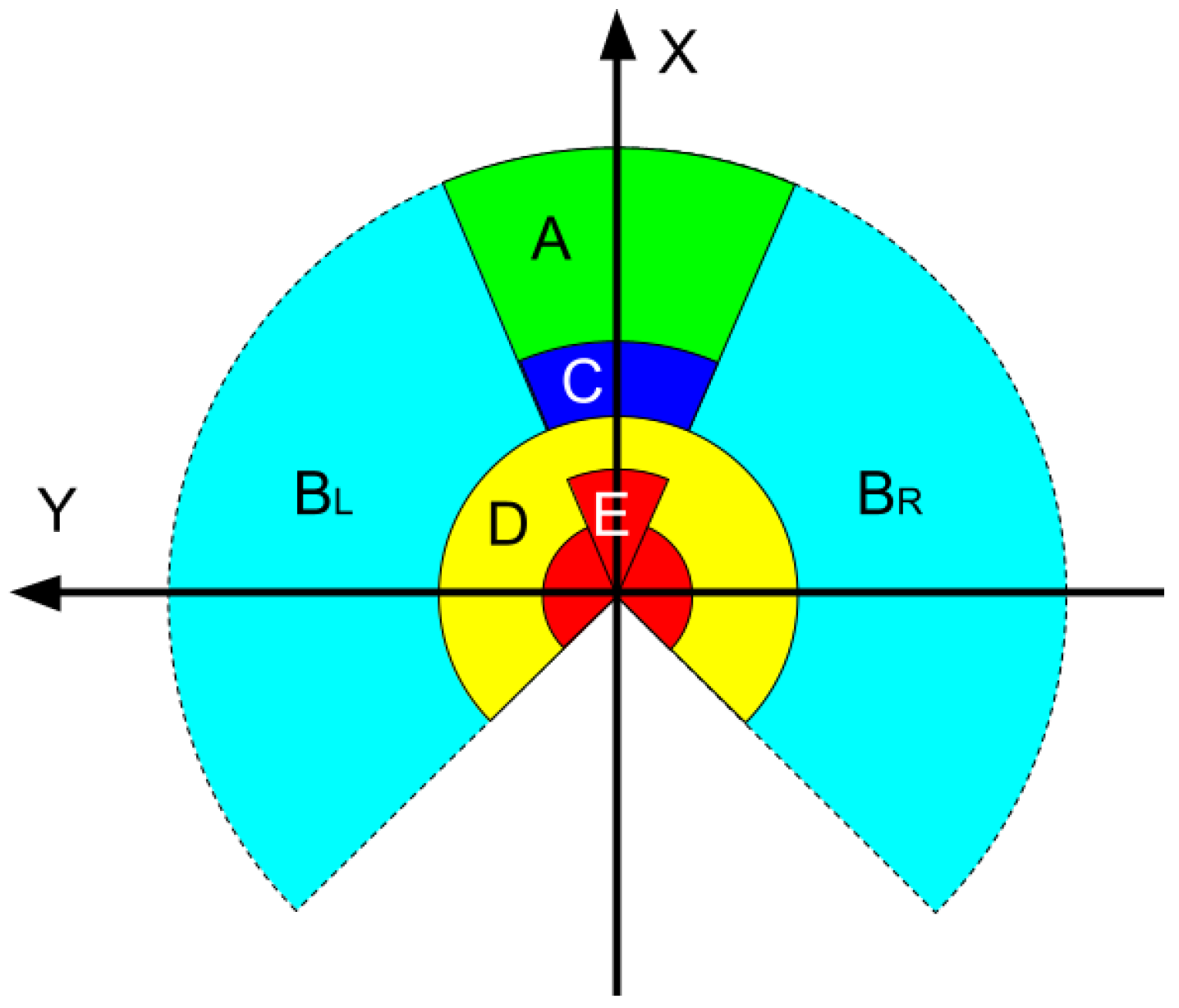
Of the steps shown above, 3 and 4 are outlined below. First, a region is set up around the robot, and the behavior of the robot is determined by which region the player to be tracked is in. This area is shown in Figure 1. When the target to be tracked is in , or C, the robot moves toward the contact point of the circle around the target. When the target enters D, the robot considers that it has touched the target and enters a disengaging motion. When the subject enters area E, the robot judges that it is too close and makes an emergency stop.

Figure 1.
The area around the robot. The radius of area E is 0.85 m, area D is 1.2 m, and area C is 1.7 m. A and B correspond to greater distances. In addition, A, C, and E are degrees from the front.
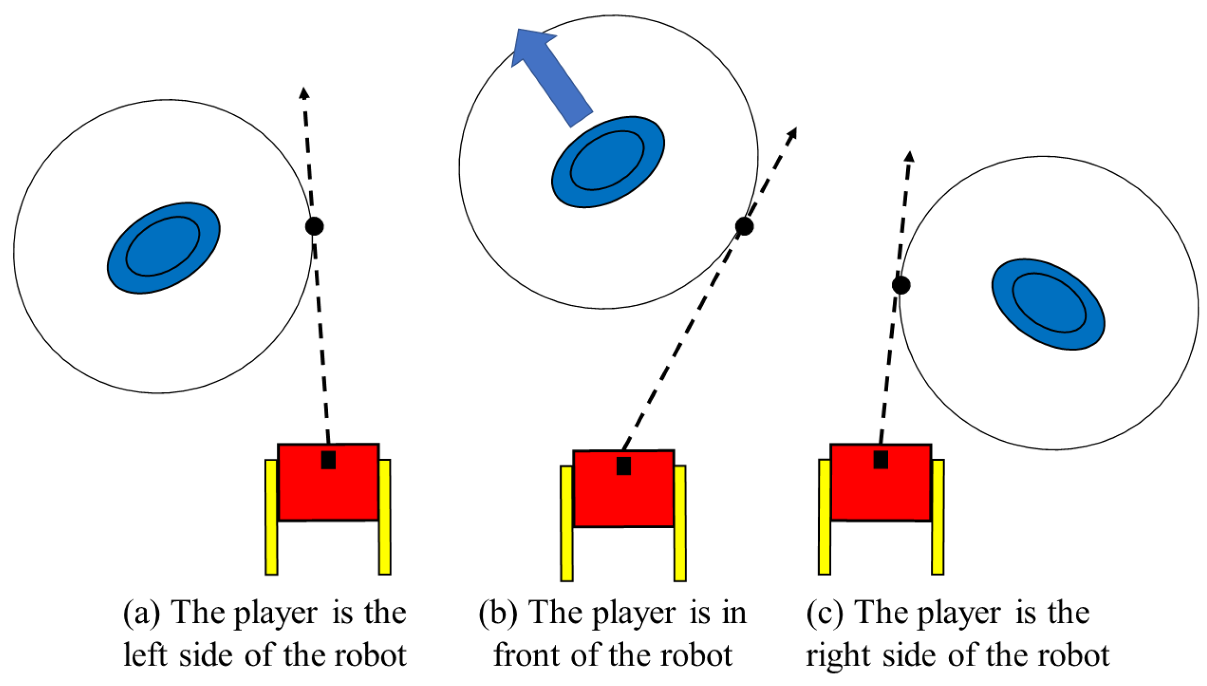
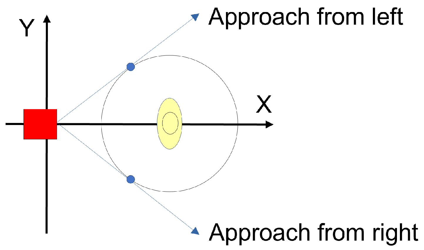
When the robot approaches the player, the target point varies depending on the relative positions of the robot and the target player, as shown in Figure 2. If the player is in area , the right contact point of the circle around the subject is the tracking target (Figure 2a). Similarly, if the player is in area , the contact point on the left side is the target point (Figure 2c). If the player is in area A, the contact point in the direction opposite to the relative angular velocity of the target becomes the target (Figure 2b). This setup allows the robot to approach the target while reducing the possibility of collision between the robot and the target as much as possible.

Figure 2.
Relative positions and target points of the robot and target.
After the robot becomes close enough to the player and is considered to have touched it, it enters a disengagement motion from the target. There were two methods of disengagement: the onward mode and the parallel mode [26]. The onward mode is the simplest method, where the robot simply moves forward for two seconds. In the parallel mode, the robot moves to avoid the collision with the player, as shown in Figure 3. Let P be the position of the target at the moment of touching the target, and let and be the angles from two points at the edge of the circle of radius r around the robot to P. The departure angle is then determined as follows.
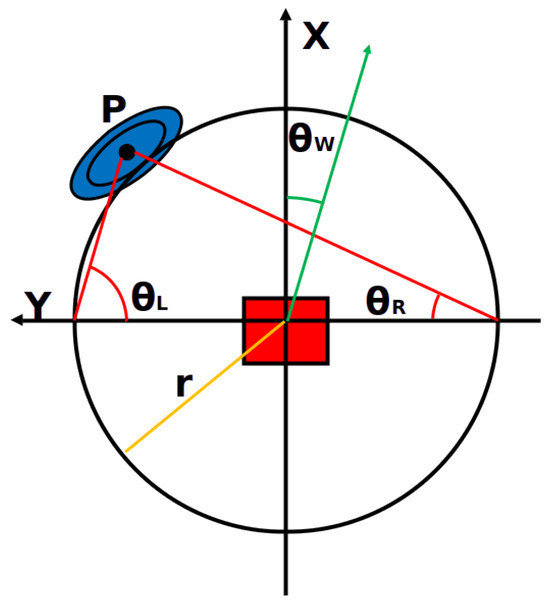
Figure 3.
The robot disengaging the player (the parallel mode). The robot’s moving direction is parallel to line .
After that, the robot disengages in the direction .
3. The Problem of the Parallel Mode
For the robot to play the role of “it” in tag playing, it needs to approach and touch the player and avoid collision with the player. To approach and touch the player, the distance between the robot and the player must be exactly the distance that the arm can reach, and the angle of the arm must match the direction of the player from the robot. The best way to control the robot depends on the mechanism of the arm. If the arm has a high degree of freedom, it should be moved to contact the player when the robot is close enough. On the other hand, if the arm is fixed to the robot’s body, the body must be controlled so that the tip of the arm touches the player.
In this section, we consider a situation where the arm is fixed to the robot’s side and propose a trajectory control of the robot required for this situation. The assumed robot and arms are shown in Figure 4. The arms are attached on both sides, and we regard robot touching the player when the robot’s arm contacts the player.
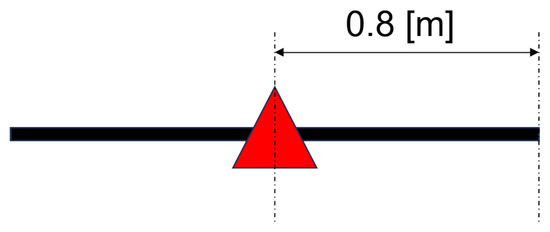
Figure 4.
The robot and the arms.
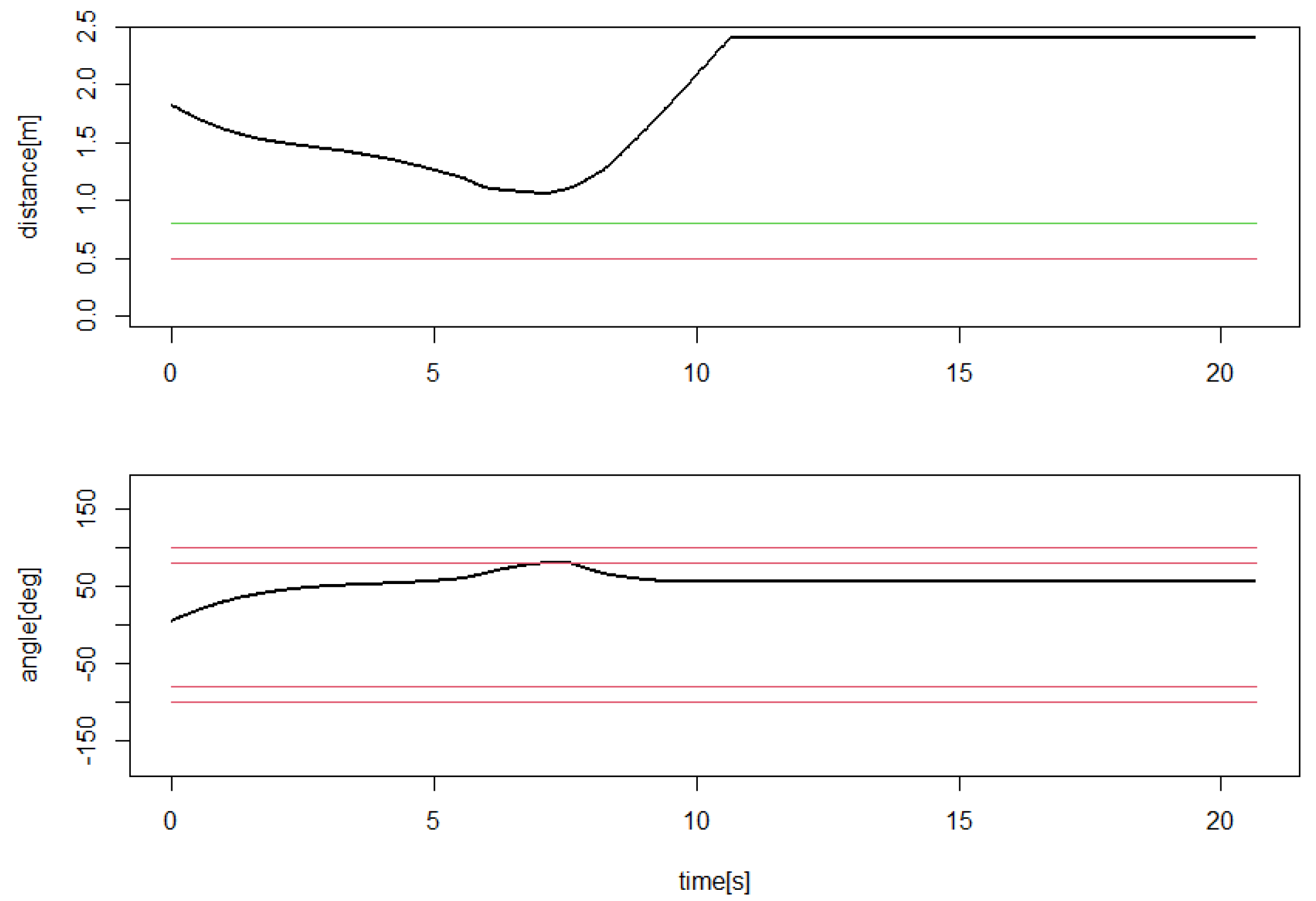
The control method explained above assumes that the touch is established when the robot is sufficiently (1 m) close to the player. As mentioned earlier, the above approach/detachment strategy would be effective if the arm mechanism could touch a player 1 m away in any direction. However, if the arm can only extend in a specific direction, this approach is likely to lead to a situation where the player is close, but the arm cannot reach them. An example of such a situation is shown in Figure 5. In this figure, the oval indicates the human position and > indicates the robot position, with arms drawn on both sides of the robot. The player and the robot are connected by a green line. At the point where the player’s trajectory is bent, the robot has decided that it is close enough to the player and has begun to disengage. Figure 6 shows the distance and angle of the player from the robot at this trajectory. The player starts to disengage when the distance from the player reaches 1.2 m. The angle at that point is about 70 degrees, and the player is not directly beside the robot (between the red lines in the graph at the bottom of Figure 6). Thus, in this example, the robot approaches the player, but the robot disengages without any contact between the robot’s arm and the player.
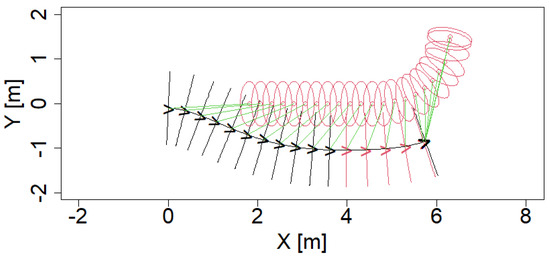
Figure 5.
An example where the robot fails to touch the player in the parallel mode. The red oval indicates the human position and black or red > indicates the robot position, with arms drawn on both sides of the robot. The red > symbol indicates that the human-robot distance is smaller than 1.2 [m]. The player and the robot are connected by a green line.
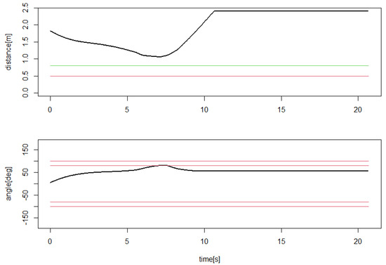
Figure 6.
The distance and orientation of the player from the robot in the situation shown in Figure 5. The green and red lines in the top figure indicate the touch distance and the emergency stop, respectively. The red lines in the bottom figure indicate the touchable angles ( degree and degree).
4. The Go-Round Mode
Given that the arm is fixed to the robot, it is possible, in principle, to control the robot so that the tip of the arm reaches the player. Various such controls are possible, but rather than strictly aligning the tip of the arm with the player, we thought that controlling the robot so that the tip of the arm can easily contact the player by manipulating the angle and distance of the robot would enable robust touch movements.
Since the arm is assumed to extend aside the robot, we assume a circular trajectory with a distance that allows the arm to reach the player’s periphery and control the robot to move along that trajectory. This is shown in Figure 7. As soon as the robot touches the player, it quickly moves away to prevent a collision. We have named this the “go-round mode”.
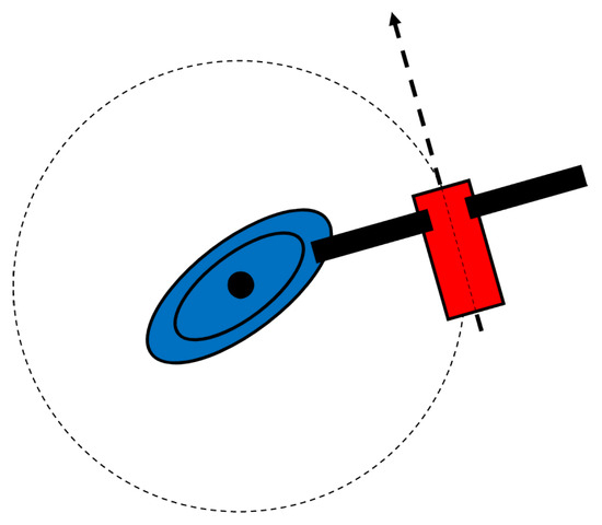
Figure 7.
The circular orbit around the player. The player is shown in a blue oval, and the robot is drawn as a red rectangle with two arms in black.
The actual control method for the go-round mode is shown in Figure 8. Since the player is moving, the circular trajectory shown in Figure 7 is not actually a circle. Therefore, assume a circle of radius around the player at a certain moment and set a point C that is advanced by an angle from the intersection point of the circle and the line connecting the robot and the player. The robot tracks this point and eventually moves to trace a circle around the player. We used [deg] in the later experiments.
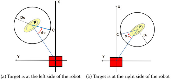
Figure 8.
Control of the go-round mode. The yellow oval is the target person, and the red square is the robot.
When is set to the distance the arm can reach, if the robot moves completely along the circle, the arm will reach the player. Once the arm touches the player, the radius of the circle increases with time, which allows rapid disengagement without changing the robot’s control method. In the later experiment, the initial value of is 0.8 [m], and after the touch, the radius increases at 1 [m/s], and when it reaches 2 [m], is not increased any further. Algorithm 1 shows the total algorithm of the go-round mode.
| Algorithm 1: Algorithm of the go-round mode | ||||
| [deg]; | ||||
| repeat | ||||
| The robot chases the target (Figure 9 of [26]); | ||||
| distance between the robot and the player; | ||||
| until [m]; | ||||
| [m]; [m]; ; | ||||
| foreach LRF scan do | ||||
| Let be the position of the player in the robot’s local coordinate; | ||||
| ; | ||||
| if the robot touches the player then | ||||
| [m/s] [s/scan]; | ||||
| Current time; | ||||
| end | ||||
| Let be a circle with center P and radius ; | ||||
|
Let be the intersection between the line and the circle where
| ||||
| ; | ||||
|
Let be the point on the circle, where | ||||
| Move the robot toward C; | ||||
| ; | ||||
| Stop the robot if and Current time [s]; | ||||
| end | ||||
5. Simulation and Experiments
5.1. Simulation
First, we conducted a simulation. In this experiment, the player’s trajectory was randomly generated, and then the virtual robot tracked the player to see if the touch was successful. We implemented the simulation program in R 4.2.2 [27]. We also use the same system for visualization such as Figure 9 and Figure 10.
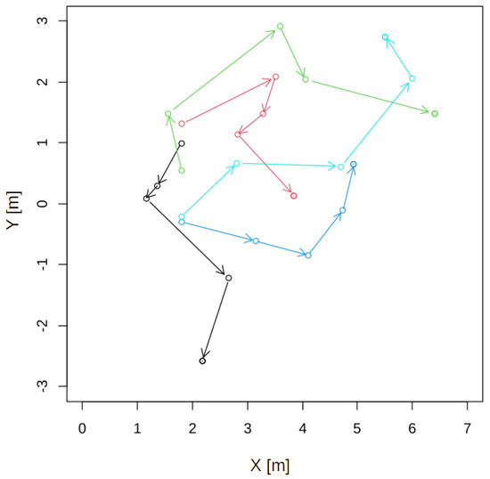
Figure 9.
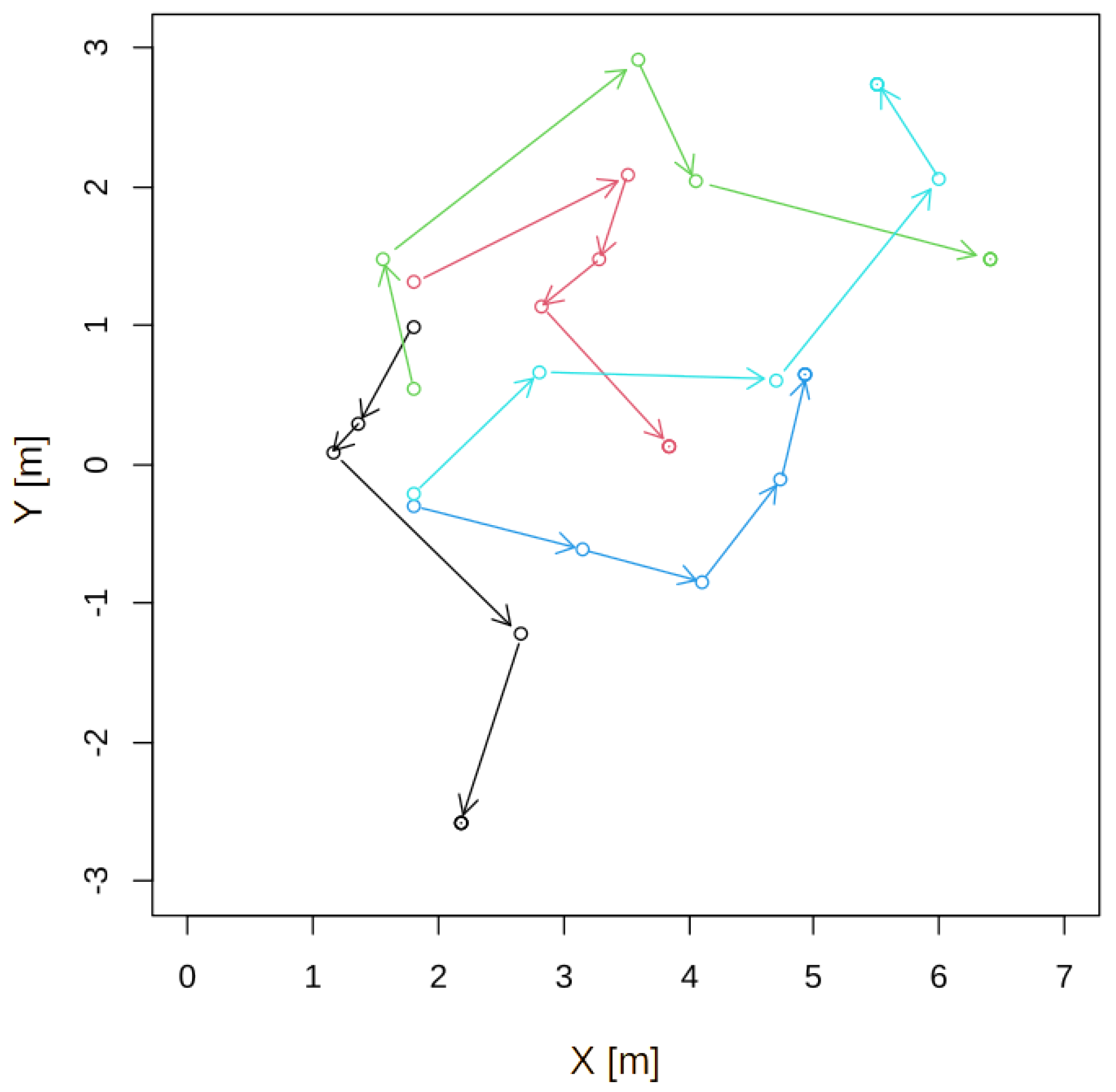
Examples of the player’s trajectories. A player’s directions were determined randomly, and a player changed direction three times. Different color shows different trajectory.
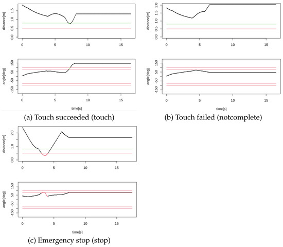
Figure 10.
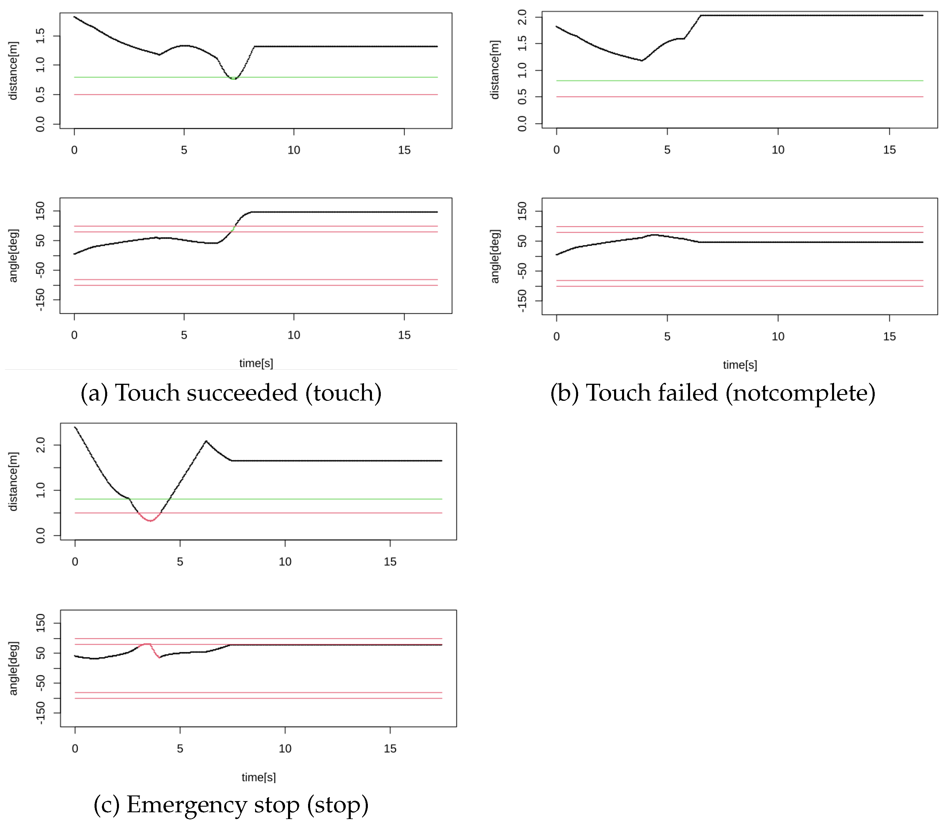
Examples of success/failure trials. Meaning of colors of the lines are the same as that in Figure 6.
An example of the player’s trajectory is shown in Figure 9. The player’s initial position was m, and Y was randomly determined between and m. The player’s trajectory was then randomly generated. The distance and direction of one step were determined by uniform random numbers . We repeated the operation four times, and the player’s path advanced by . The player stops at the final position. The player was assumed to move forward at a constant velocity on the trajectory generated in this way. The robot’s initial position was (0,0), and it tracks the player at a speed of 0.75 m/s.
In the simulation, we regarded that the robot touched the player if the player was at an angle of 80 to 100 degrees or to degrees from the robot and the distance was 0.8 m or less. However, if the distance was 0.5 m or less, the robot stopped to avoid collision. Thus, the robot could either succeed in touching, fail to touch until the end, or make an emergency stop. Figure 10 shows examples of distances and angles of the player from the robot. The green part of the curve indicates that the robot touches the player, and the red portion shows that the player enters the emergency stop area. In the simulation, if the player enters the emergency stop area after the touch, we regarded that the robot successfully touched the player; conversely, if the player enters the emergency stop area before the touch is established, it is regarded as an “emergency stop”.
In the simulation, 100 player trajectories were generated. We tried three control methods: the onward mode, the parallel mode, and the go-round mode. In addition, we tried three human velocities, 0.5 [m/s], 0.6 [m/s], and 0.75 [m/s]. Since the robot moves at 0.75 [m/s], 0.5 [m/s], and 0.6 [m/s], human velocity condition is the case where the robot moves sufficiently faster than the human. When the human velocity was 0.75 [m/s], the human and the robot moved at the same speed. Therefore, the robot would touch the human after the human stopped at the last position.
The results are shown in Figure 11. The results show that the go-round mode showed consistently better results for all conditions. Among the conventional methods, the parallel mode showed larger touch rate and smaller stop rate, which was consistent with the literature [21]. In addition, when the human velocity was fast, the touch rate of the robot decreased.
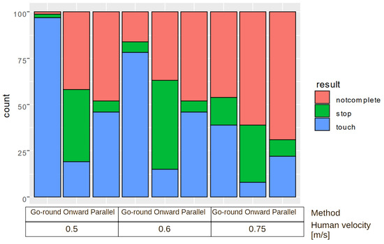
Figure 11.
The simulation result.
5.2. Experiment Using a Real Robot
5.2.1. The Robot
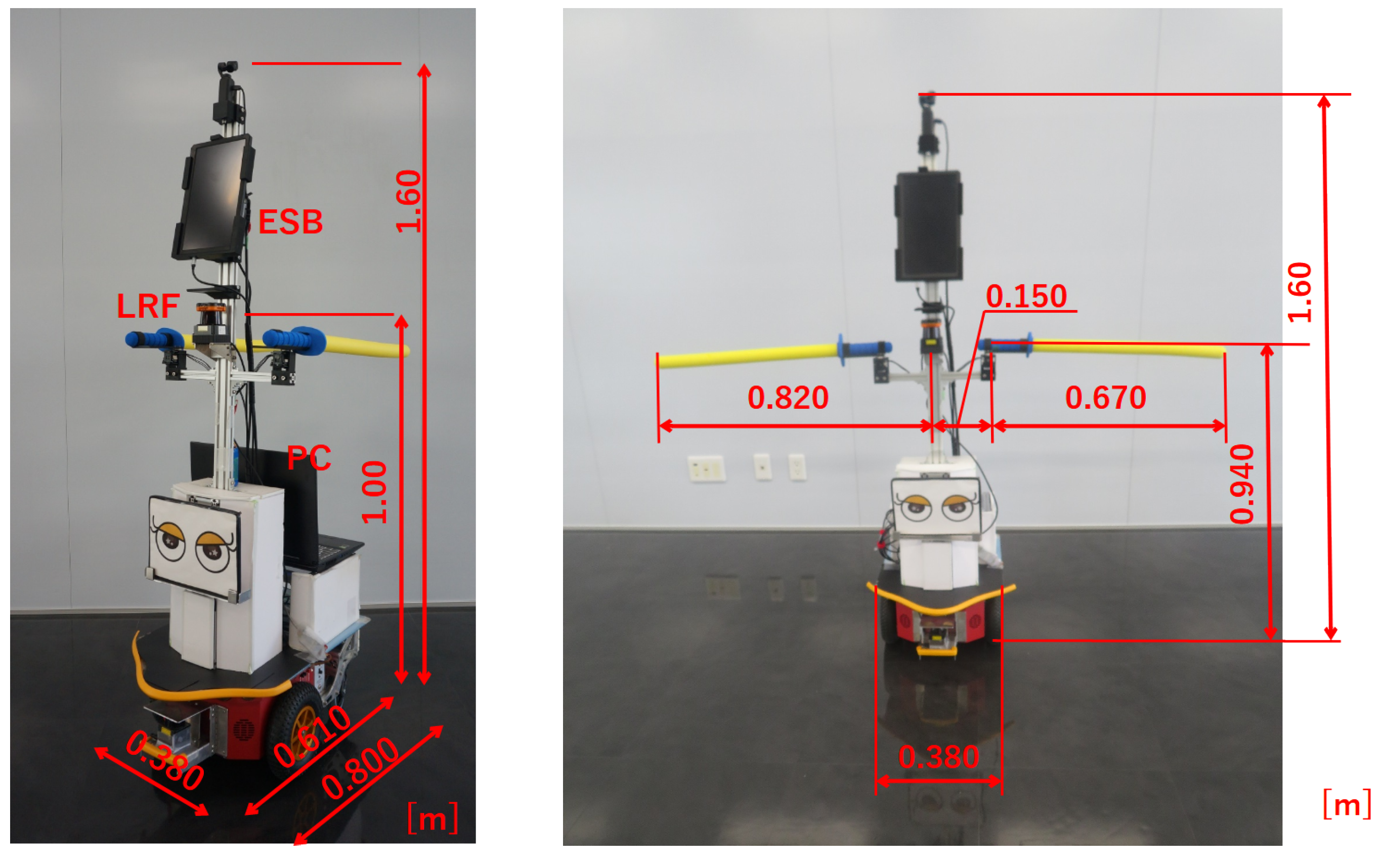
We experimented using an actual robot shown in Figure 12. The mobile robot was based on Pioneer 3DX (manufactured by MobileRobots Inc., currently Omron Adept Technology, Pleasanton, CA, USA), a two-wheeled mobile robot. The maximum translational speed of the robot was 0.75 [m/s], and the maximum angular velocity was set to 110 [deg/s]. The robot size is 0.380 (1.64 when the arm is deployed) × 0.610 × 1.60 [m] WDH. The total weight is 26 [kg]. The robot had two 1-DOF arms that moved horizontally on both sides. The motors (Dynamixel MX-28AR, manufactured by ROBOTIC Co. Ltd., Seoul, South Korea) equipped with a torque limit were used for moving the arms. We sensed an arm’s contact with a player by measuring the load torque of the motor. When the load torque exceeds the threshold, we judge the arm contacts with a human, and the torque is released. The threshold was determined empirically through preliminary experiments. The arms are made of lightweight polyethylene foam to ensure safety. The arm’s length is determined based on the human body size and shape database (upper limb length) [28]. The LRF for human detection used was the UTM-30LX (manufactured by Hokuyo Electric, Osaka, Japan), which was installed at a height of 1.0 [m] and could measure a two-dimensional distance of up to 30 [m] at 270 [deg].
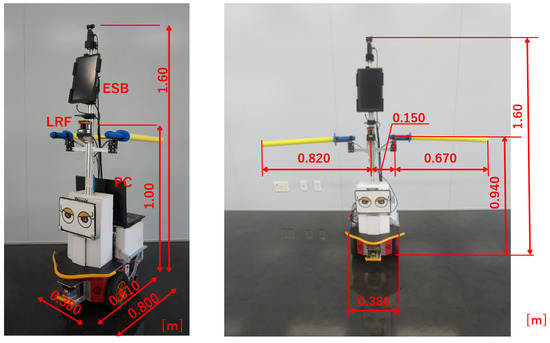
Figure 12.
The robot used for the experiment.
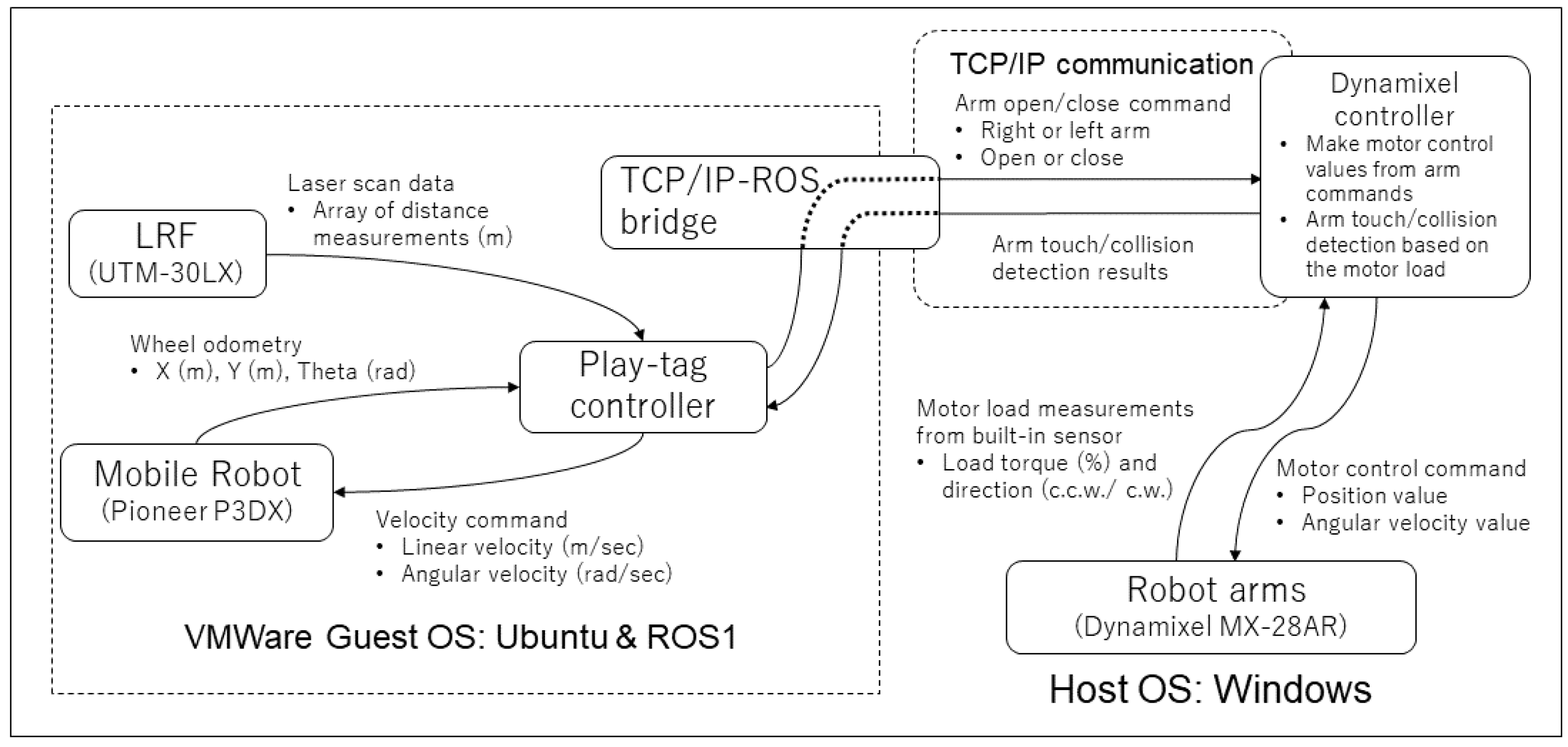
A laptop PC (MouseComputer DAIV5N CPU: Intel(R)Core(TM)i7-9750H@2.60GHz, Memory: 32 GB) was installed behind the robot to control the entire robot. The emergency stop switch was installed at the top of the robot. Figure 13 shows the system’s block diagram. The system works on Windows 10, where the robot control system is operated in ROS melodic on Ubuntu 18.04 LTS that runs on VMware. The communication system between the robot and the arms runs on Windows, which communicates with ROS using TCP/IP.
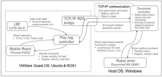
Figure 13.
The system diagram.
5.2.2. The First Experiment
In the first experiment, the robot and the player moved at a similar speed. The experiment was conducted in a carpeted foyer, and one male player participated. We prepared three paths, as shown in Figure 14. We determined these trajectories based on the observation of tag plays by human players [21]. The three trajectories, straight, curved, and zigzag, are frequently observed as motions of players in those plays. We also used the same trajectories in our previous work [21].
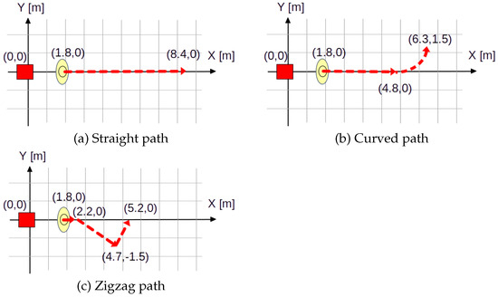
Figure 14.
The experimental environments.
The player walked at a velocity of 0.74 [m/s] by synchronizing the sound of a metronome, and the robot chased the player at a velocity of 0.75 [m/s]. After walking the entire path, the player stayed at the end of the path.
We conducted two trials for one path and one method. Since the robot and the player are initially on the X-axis, two virtual targets can be around the player, as shown in Figure 15. Therefore, we set the robot to choose the left () target in one trial and the right () one in another trial. Since we tried two methods, the parallel mode and the go-round mode, the experiment was conducted 12 times (3 paths × 2 directions (left and right) × 2 methods). We used robot odometry to obtain the robot’s trajectory, and the player’s position was estimated from the player’s position observed by LRF and the robot’s odometry.
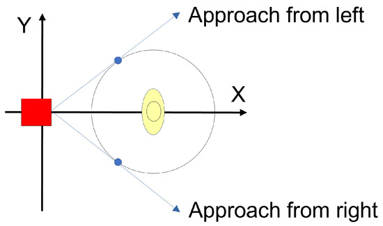
Figure 15.
Two virtual targets at the initial state.
Table 1 shows the experimental results. The parallel mode failed in two out of six trials. In the failed trials, the robot approaches the player from the right side.

Table 1.
Results of the experiment by a real robot.
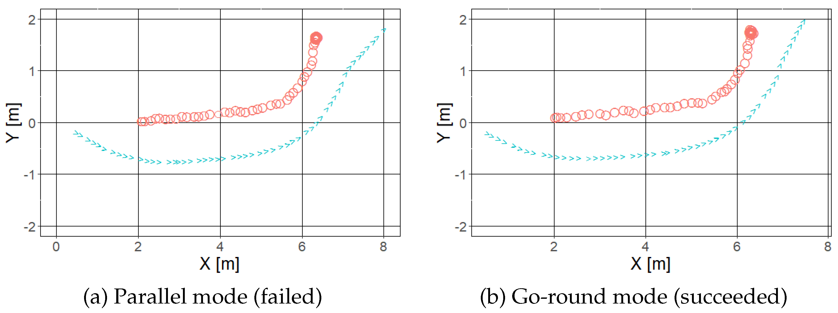
Figure 16 shows the trajectories of the robot and the player of the curved path by the parallel and go-round mode. The blue and red marks in these figures show the robot and the player trajectories, respectively. When the robot used the parallel mode, the robot decided to disengage when the arm could not reach the player, and the player moved to the opposite side of the robot, which caused the touch to fail. When employing the go-round mode, the robot moved toward the player until it moved aside from the player.
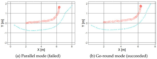
Figure 16.
An example of trajectories for the curved path. The blue and red marks show the robot and the player trajectories, respectively.
5.2.3. The Second Experiment
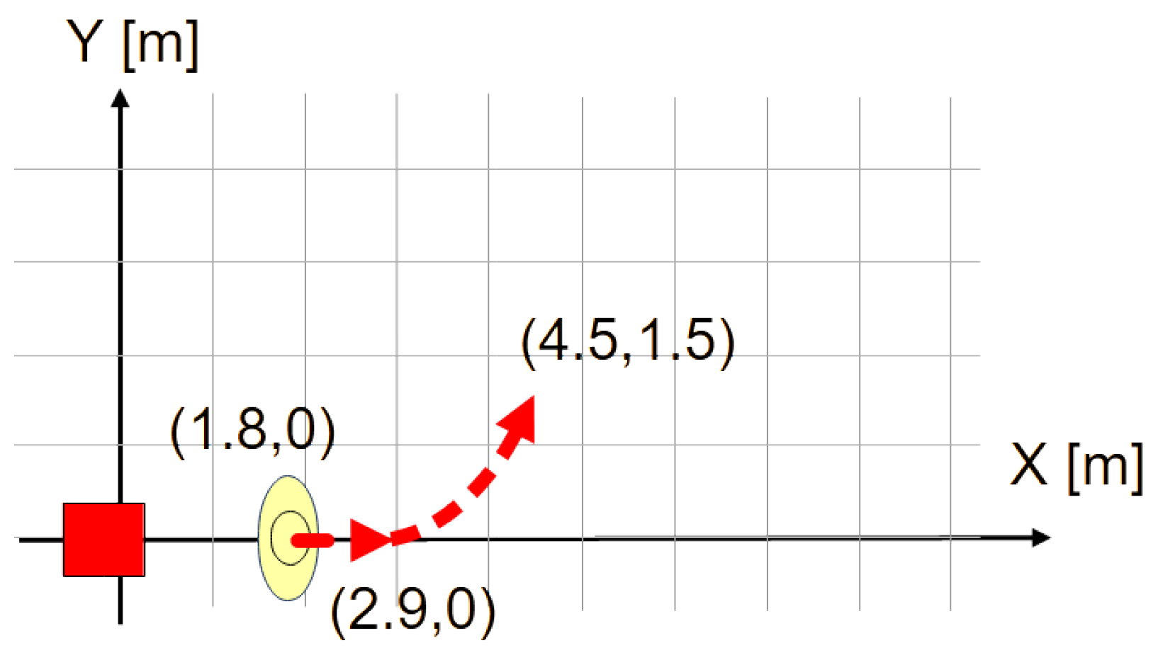
In the previous experiment, we compared the parallel and go-round modes and found that the go-round mode allowed the robot to continue to follow and touch the player. However, in the previous experiment, the player stopped at the final point, and the robot touched the player at the final point. Therefore, we conducted the following experiment in which the player continued to move even if the robot touched them. In this experiment, we used only the go-round mode. In this experiment, we used three paths similar to the previous one: straight, curved, and zigzag. The straight and zigzag paths are the same as those shown in Figure 14. The curved path in this experiment is shown in Figure 17. The player’s walking velocity was 0.37 [m/s] for the curved and straight paths and 0.5 [m/s] for the zigzag path. The robot’s velocity was 0.75 [m/s].
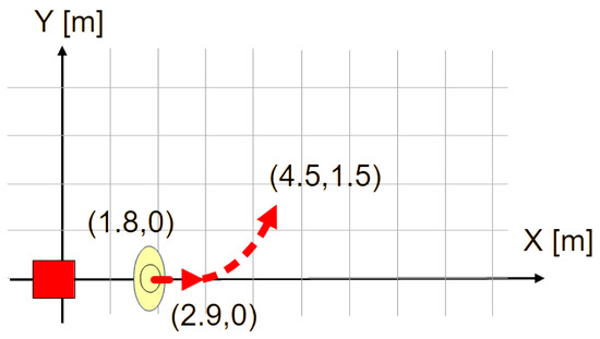
Figure 17.
The curved path in the second experiment.
We conducted six trials (3 paths × 2 directions (left and right)). As a result, the robot succeeded in touching the player in all the trials. The minimum distances of all the conditions are shown in Table 2.
Table 2.
Results of the second experiment with the go-round method.
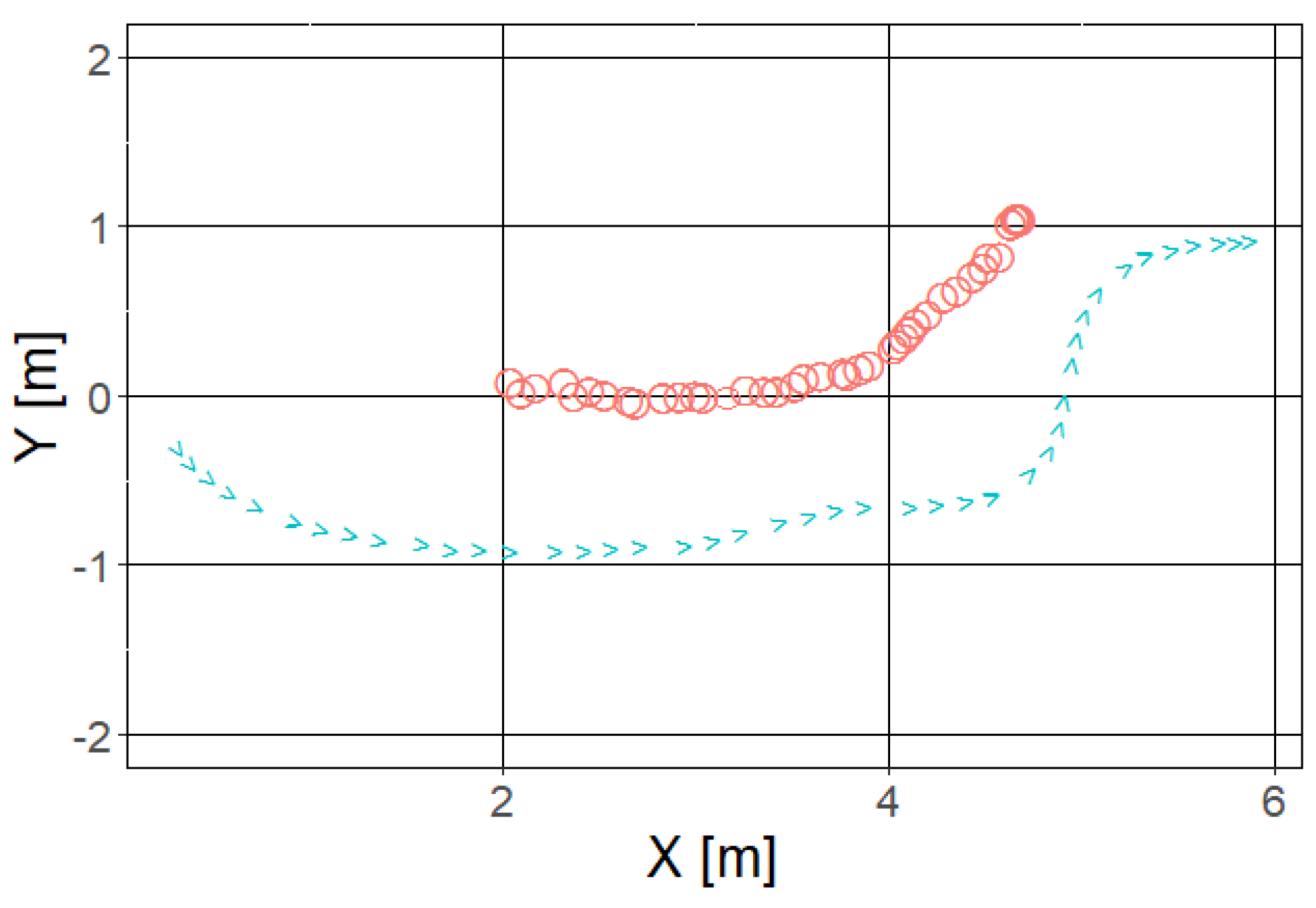
Figure 18 shows the trajectories of the player and the robot for the curve trajectory and right target. When the robot approached the player, it once tried to keep a distance from the player to follow the virtual target on the virtual circle around the player. Then, the robot moved aside from the player and touched successfully. The video of the experiment is provided as the Supplementary Material.
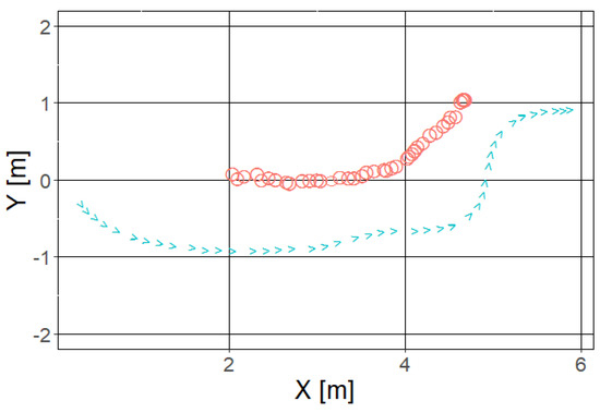
Figure 18.
A trajectory for the curved path (right). The blue and red marks show the robot and the player trajectories, respectively.
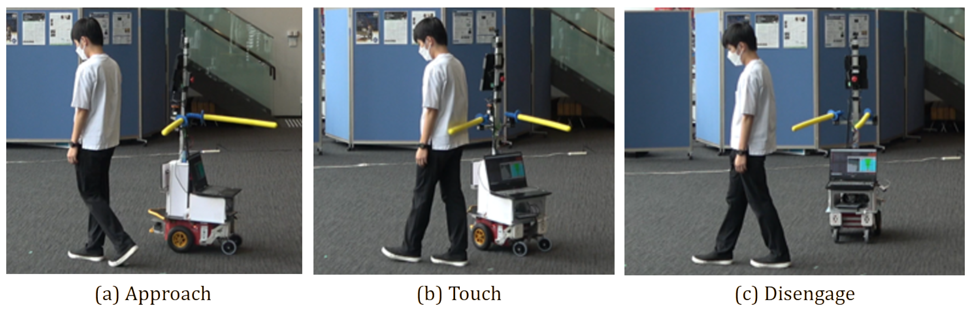
Figure 19 shows the photos of the robot’s touching behavior. The robot approached from behind the player, touched the arm, and changed the direction opposite to the player’s moving direction for disengagement.
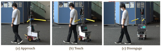
Figure 19.
The robot touching the walking player.
6. Conclusions
This research aims to realize touch operation with a tag-playing robot against a player. Specifically, we develop a robot with touch functionality and enable this robot to perform touch actions for players. First, as in the previous report, we describe the realization of “Touch-and-Away” behavior based on LRF to approach a player in a game of tag. In the parallel mode proposed in the previous report, the robot performed the “Touch-and-Away” behavior while keeping a sufficient distance from the player; however, when we employed fixed arms, it eventually failed to touch the player. Therefore, we proposed the “go-round” mode. The proposed method enabled the robot to touch the player even when the parallel mode failed to touch, and the robot with the proposed method succeeded in touching the player when the robot and the human moved together.
The contribution of this research is that it enables touch interaction (dynamic touch interaction) when the robot and human are moving together. Limitations of the proposed method are that it has difficulty in avoiding collisions with players who intentionally approach the robot.
There are many challenges in actual tag games. In this work, we assume only one player is in the field, but we need to assume many players in a real tag play. In this case, we believe it is possible to keep chasing the nearest player. If the game follows the rules of a regular game of tag, the player and “it” should switch roles.
In addition, we need to consider not only the robot’s performance but also its psychological effects, such as threat to the player [29].
Supplementary Materials
The following supporting information can be downloaded at: https://www.mdpi.com/article/10.3390/app132312909/s1.
Author Contributions
Conceptualization, K.M.; validation, Y.H.; software K.M. and Y.H.; simulation, A.I.; methodology, formal analysis, investigation, Y.H.; resources, experiment, Y.H.; data curation, Y.H.; writing—original draft preparation, A.I.; writing—review and editing, A.I.; visualization, A.I.; supervision, A.I.; project administration, Y.H.; funding acquisition, Y.H. All authors have read and agreed to the published version of the manuscript.
Funding
This research was funded by JSPS Kakenhi JP20K04389.
Institutional Review Board Statement
This study was conducted according to the guidelines of the Declaration of Helsinki and approved by the Life Science Ethics Committee of Osaka Institute of Technology (approval number 2019-18-3, 15 March 2022).
Informed Consent Statement
Informed consent was obtained from all subjects involved in the study.
Data Availability Statement
The data presented in this study are available on request from the corresponding author. The data are not publicly available due to privacy.
Acknowledgments
Yoshitaka Kasai and Hironobu Wakabayashi contributed to conducting the experiment.
Conflicts of Interest
The authors declare no conflict of interest.
References
- Matveev, A.S.; Wang, C.; Savkin, A.V. Real-time navigation of mobile robots in problems of border patrolling and avoiding collisions with moving and deforming obstacles. Robot. Auton. Syst. 2012, 60, 769–788. [Google Scholar] [CrossRef]
- Dragan, A.D.; Bauman, S.; Forlizzi, J.; Srinivasa, S.S. Effects of robot motion on human-robot collaboration. In Proceedings of the Tenth Annual ACM/IEEE International Conference on Human-Robot Interaction, Portland, OR, USA, 2–5 March 2015; pp. 51–58. [Google Scholar]
- Gallace, A.; Spence, C. The science of interpersonal touch: An overview. Neurosci. Biobehav. Rev. 2010, 34, 246–259. [Google Scholar] [CrossRef] [PubMed]
- Ferrari, E.; Robins, B.; Dautenhahn, K. Therapeutic and educational objectives in robot assisted play for children with autism. In Proceedings of the 18th IEEE Int. Symp. on Robot and Human Interactive Communication (RO-MAN), Toyama, Japan, 27 September–2 October 2009; pp. 108–114. [Google Scholar] [CrossRef]
- Matsumaru, T.; Horiuchi, Y.; Akai, K.; Ito, Y. Truly-Tender-Tailed Tag-Playing Robot Interface through Friendly Amusing Mobile Function. J. Robot. Mechatron. 2010, 22, 301–307. [Google Scholar] [CrossRef]
- Ogawa, M.; Shimizu, S.; Kadogawa, T.; Hashizume, T.; Kudoh, S.; Suehiro, T.; Sato, Y.; Ikeuchi, K. Development of Air Hockey Robot improving with the human players. In Proceedings of the IECON 2011—37th Annual Conference of the IEEE Industrial Electronics Society, Melbourne, VIC, Australia, 7–10 November 2011; pp. 3364–3369. [Google Scholar] [CrossRef]
- Wainer, J.; Robins, B.; Amirabdollahian, F.; Dautenhahn, K. Using the Humanoid Robot KASPAR to Autonomously Play Triadic Games and Facilitate Collaborative Play Among Children With Autism. IEEE Trans. Auton. Ment. Dev. 2014, 6, 183–199. [Google Scholar] [CrossRef]
- Laue, T.; Birbach, O.; Hammer, T.; Frese, U. An Entertainment Robot for Playing Interactive Ball Games. In RoboCup 2013: Robot World Cup XVII; Behnke, S., Veloso, M., Visser, A., Xiong, R., Eds.; Springer: Berlin/Heidelberg, Germany, 2014; pp. 171–182. [Google Scholar] [CrossRef]
- AlAttar, A.; Rouillard, L.; Kormushev, P. Autonomous Air-Hockey Playing Cobot Using Optimal Control and Vision-Based Bayesian Tracking. In Towards Autonomous Robotic Systems; Althoefer, K., Konstantinova, J., Zhang, K., Eds.; Springer: Cham, Swirzerland, 2019; pp. 358–369. [Google Scholar] [CrossRef]
- Hiroi, Y.; Ito, A. Realization of a robot system that plays “Darumasan-Ga-Koronda” Game with Humans. Robotics 2019, 8, 55. [Google Scholar] [CrossRef]
- Flanders, J.L.; Leo, V.; Paquette, D.; Pihl, R.O.; Séguin, J.R. Rough-and-tumble play and the regulation of aggression: An observational study of father–child play dyads. Aggress. Behav. Off. J. Int. Soc. Res. Aggress. 2009, 35, 285–295. [Google Scholar] [CrossRef] [PubMed]
- Flanders, J.L.; Simard, M.; Paquette, D.; Parent, S.; Vitaro, F.; Pihl, R.O.; Séguin, J.R. Rough-and-tumble play and the development of physical aggression and emotion regulation: A five-year follow-up study. J. Fam. Violence 2010, 25, 357–367. [Google Scholar] [CrossRef]
- Storli, R. Characteristics of indoor rough-and-tumble play (R&T) with physical contact between players in preschool. Nord. Barnehageforskning 2013, 6, 1–15. [Google Scholar]
- Geravand, M.; Flacco, F.; De Luca, A. Human-robot physical interaction and collaboration using an industrial robot with a closed control architecture. In Proceedings of the 2013 IEEE International Conference on Robotics and Automation, Karlsruhe, Germany, 6–10 May 2013; IEEE: Piscataway, NJ, USA, 2013; pp. 4000–4007. [Google Scholar] [CrossRef]
- Magrini, E.; Flacco, F.; De Luca, A. Control of generalized contact motion and force in physical human-robot interaction. In Proceedings of the 2015 IEEE international conference on robotics and automation (ICRA), Seattle, WA, USA, 26–30 May 2015; IEEE: Piscataway, NJ, USA, 2015; pp. 2298–2304. [Google Scholar] [CrossRef]
- Vick, A.; Surdilovic, D.; Krüger, J. Safe physical human-robot interaction with industrial dual-arm robots. In Proceedings of the 9th International Workshop on Robot Motion and Control, Kuslin, Poland, 3–5 July 2013; pp. 264–269. [Google Scholar] [CrossRef]
- Costa, S.; Lehmann, H.; Dautenhahn, K.; Robins, B.; Soares, F. Using a humanoid robot to elicit body awareness and appropriate physical interaction in children with autism. Int. J. Soc. Robot. 2015, 7, 265–278. [Google Scholar] [CrossRef]
- Robins, B.; Dautenhahn, K. Tactile interactions with a humanoid robot: Novel play scenario implementations with children with autism. Int. J. Soc. Robot. 2014, 6, 397–415. [Google Scholar] [CrossRef]
- Gerndt, R.; Seifert, D.; Baltes, J.H.; Sadeghnejad, S.; Behnke, S. Humanoid robots in soccer: Robots versus humans in RoboCup 2050. IEEE Robot. Autom. Mag. 2015, 22, 147–154. [Google Scholar] [CrossRef]
- Pavlichenko, D.; Ficht, G.; Amini, A.; Hosseini, M.; Memmesheimer, R.; Villar-Corrales, A.; Schulz, S.M.; Missura, M.; Bennewitz, M.; Behnke, S. RoboCup 2022 AdultSize Winner NimbRo: Upgraded Perception, Capture Steps Gait and Phase-based In-walk Kicks. In RoboCup 2022: Robot World Cup XXV; Springer: Berlin/Heidelberg, Germany, 2023; pp. 240–252. [Google Scholar] [CrossRef]
- Kasai, Y.; Hiroi, Y.; Miyawaki, K.; Ito, A. Development of a mobile robot that plays tag with touch-and-away behavior using a laser range finder. Appl. Sci. 2021, 11, 7522. [Google Scholar] [CrossRef]
- Moreno, A.; Van Delden, R.; Poppe, R.; Reidsma, D.; Heylen, D. Augmenting traditional playground games to enhance game experience. In Proceedings of the 2015 7th International Conference on Intelligent Technologies for Interactive Entertainment (INTETAIN), Turin, Italy, 10–12 June 2015; IEEE: Piscataway, NJ, USA, 2015; pp. 140–149. [Google Scholar]
- Saleh, S.; Mahdi, H.; Dautenhahn, K. Let’s Play Together: Designing Robots to Engage Children with Special Needs and Their Peers in Robot-Assisted Play. In Proceedings of the Companion of the 2021 ACM/IEEE International Conference on Human-Robot Interaction, Boulder, CO, USA, 8–11 March 2021; pp. 586–588. [Google Scholar]
- Ikemoto, K.; Hiroi, Y.; Ito, A. Evaluation of Person Tracking Methods for Human-Robot Physical Play. In Proceedings of the 2020 IEEE/SICE International Symposium on System Integration (SII), Honolulu, HI, USA, 12–15 January 2020; pp. 416–421. [Google Scholar] [CrossRef]
- Hiroi, Y.; Matsunaka, S.; Ito, A. A mobile robot system with semi-autonomous navigation using simple and robust person following behavior. J. Man Mach. Technol. 2012, 1, 44–62. [Google Scholar]
- Kasai, Y.; Hiroi, Y.; Miyawaki, K.; Ito, A. Development of a Teleoperated Play Tag Robot with Semi-Automatic Play. In Proceedings of the 2022 IEEE/SICE International Symposium on System Integration (SII), Narvik, Norway, 9–12 January 2022; IEEE: Piscataway, NJ, USA, 2022; pp. 165–170. [Google Scholar]
- R Core Team. R: A Language and Environment for Statistical Computing; R Foundation for Statistical Computing: Vienna, Austria, 2022. [Google Scholar]
- Artifical Intelligence Research Center. Human Body Size and Shape Database 2003. 2003. Available online: https://www.airc.aist.go.jp/dhrt/dhdb.html (accessed on 1 October 2023).
- Hiroi, Y.; Ito, A. Effect of the size factor on psychological threat of a mobile robot moving toward human. KANSEI Eng. Int. 2009, 8, 51–58. [Google Scholar] [CrossRef]


Disclaimer/Publisher’s Note: The statements, opinions and data contained in all publications are solely those of the individual author(s) and contributor(s) and not of MDPI and/or the editor(s). MDPI and/or the editor(s) disclaim responsibility for any injury to people or property resulting from any ideas, methods, instructions or products referred to in the content. |
© 2023 by the authors. Licensee MDPI, Basel, Switzerland. This article is an open access article distributed under the terms and conditions of the Creative Commons Attribution (CC BY) license (https://creativecommons.org/licenses/by/4.0/).