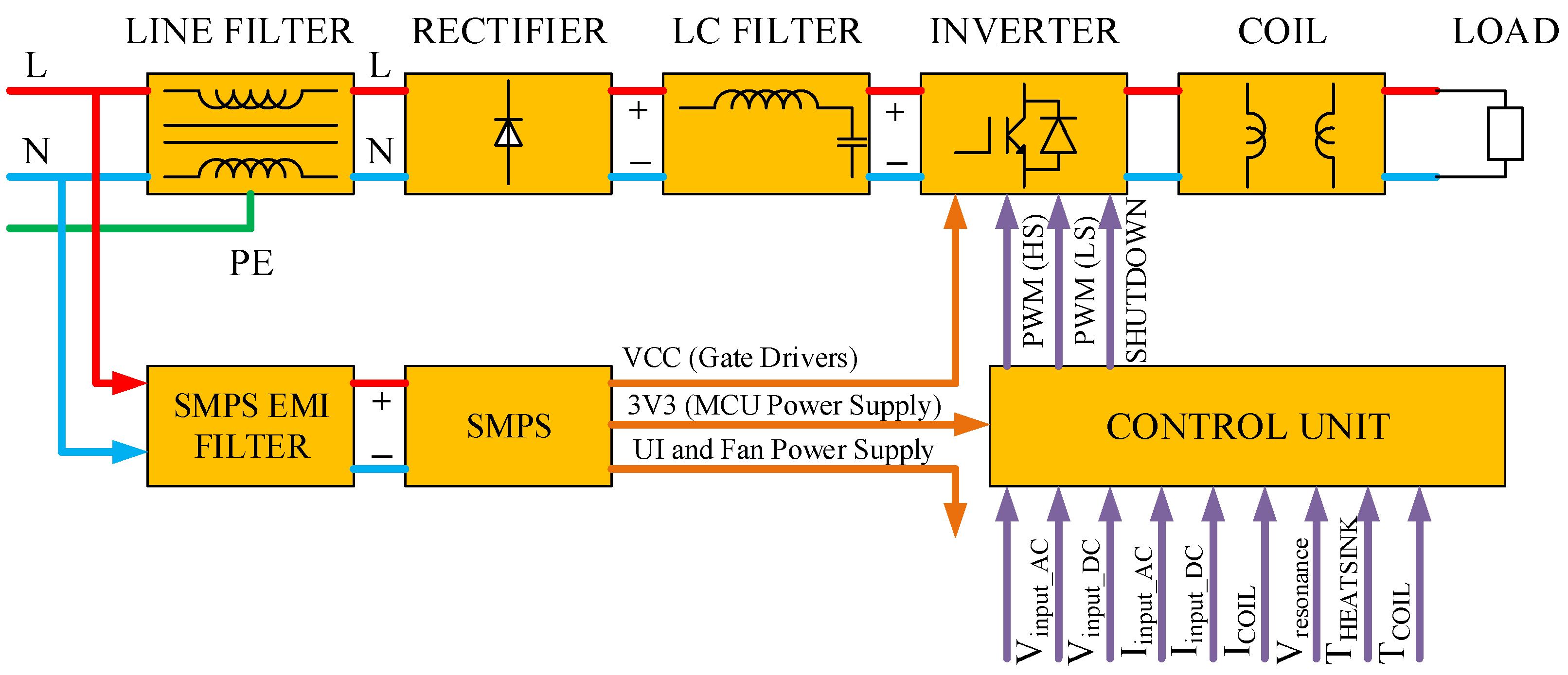
Figure 1.
Basic building block of domestic induction heating systems.
Figure 1.
Basic building block of domestic induction heating systems.
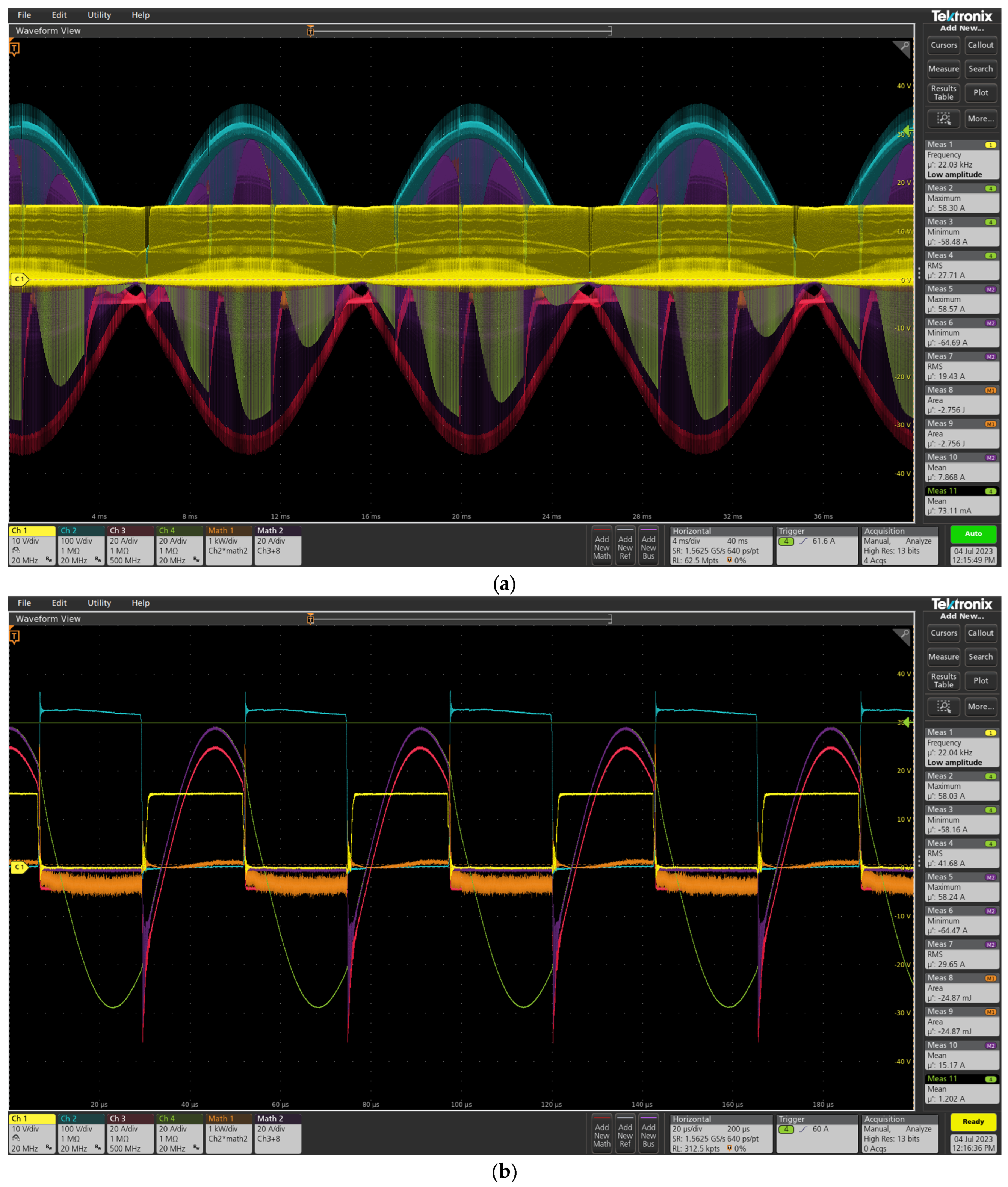
Figure 2.
Operating condition-1 waveforms: (a) 4 ms/div; (b) 20 µs/div. Yellow waveform: gate drive signal, blue waveform: IGBT VCE voltage, red waveform: IGBT IC current measured by Rogowski coil, green waveform: induction coil current, purple waveform (math2): IGBT current without Rogowski offset, orange waveform: IGBT power loss.
Figure 3.
Operating condition-2 waveforms: (a) 4 ms/div; (b) 20 µs/div. Yellow waveform: gate drive signal, blue waveform: IGBT VCE voltage, red waveform: IGBT IC current measured by Rogowski coil, green waveform: induction coil current, purple waveform (math2): IGBT current without Rogowski offset, orange waveform: IGBT power loss.
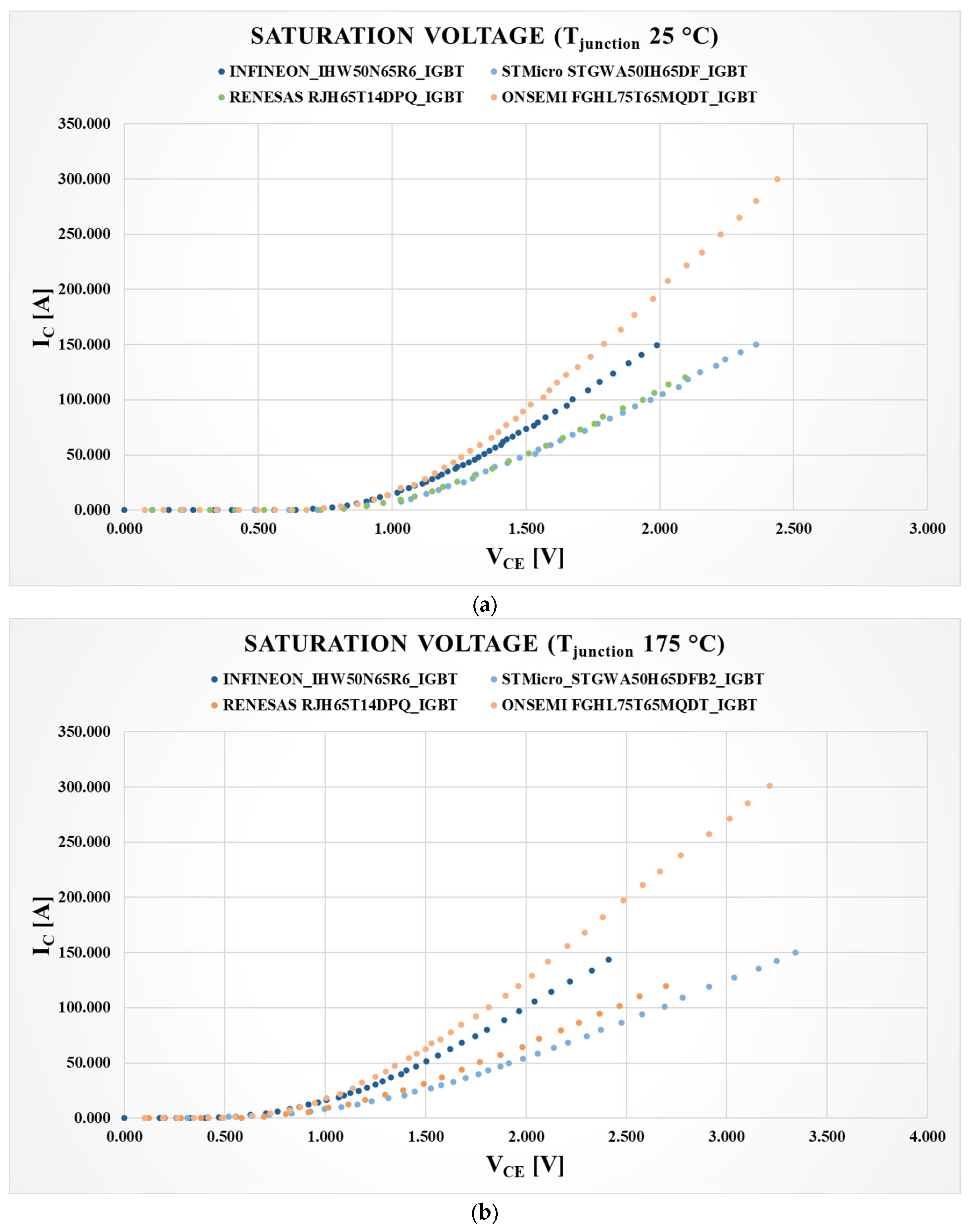
Figure 4.
IGBT saturation voltages at different junction temperatures: (a) IGBT voltages at 25 C junction temperature; (b) IGBT voltages at 175 C junction temperature.
Figure 4.
IGBT saturation voltages at different junction temperatures: (a) IGBT voltages at 25 C junction temperature; (b) IGBT voltages at 175 C junction temperature.
Figure 5.
Diode voltages at different junction temperatures: (a) Diode voltages at 25 C junction temperature; (b) Diode voltages at 175 C junction temperature.
Figure 5.
Diode voltages at different junction temperatures: (a) Diode voltages at 25 C junction temperature; (b) Diode voltages at 175 C junction temperature.
Figure 6.
Characteristics of selected power semiconductors for domestic induction heating application: (a) IHW50N65R6 IGBT characteristics for different junction temperatures; (b) GS66516B characteristics for different junction temperatures; (c) Reverse conduction characteristics for both.
Figure 6.
Characteristics of selected power semiconductors for domestic induction heating application: (a) IHW50N65R6 IGBT characteristics for different junction temperatures; (b) GS66516B characteristics for different junction temperatures; (c) Reverse conduction characteristics for both.
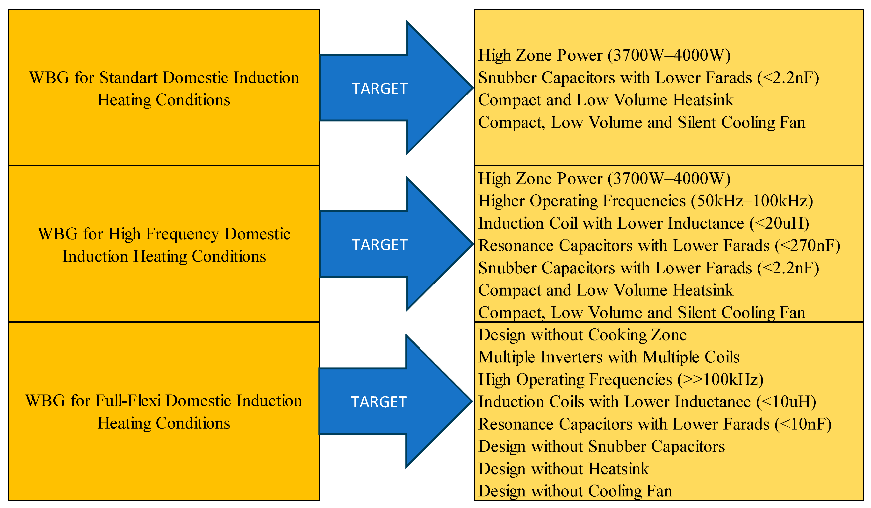
Figure 7.
Roadmap to use WBG power semiconductors in domestic induction heating applications.
Figure 7.
Roadmap to use WBG power semiconductors in domestic induction heating applications.
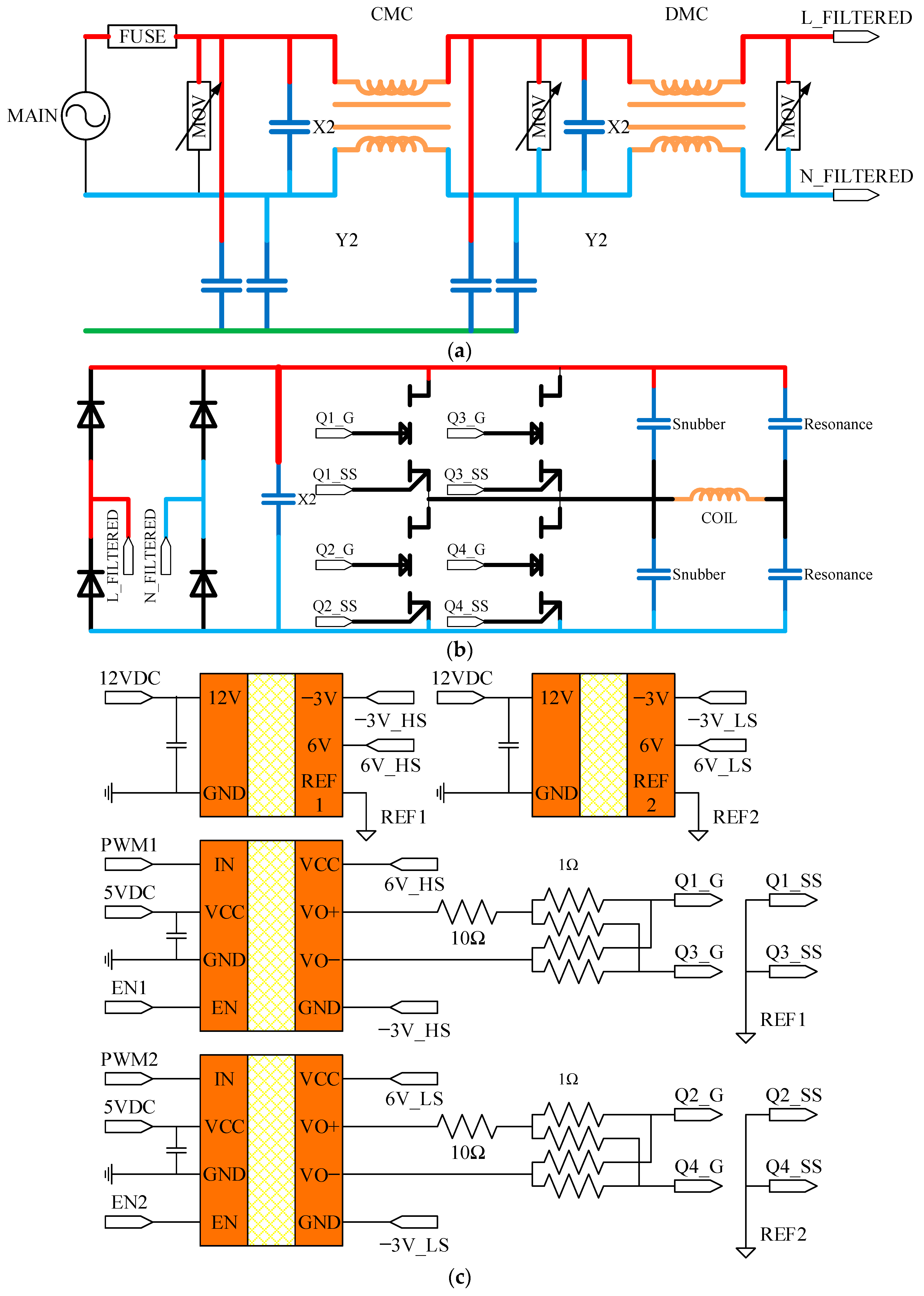
Figure 8.
Power sections are used in measurements. (a) Line filter; (b) Resonance Converter; (c) Gate driver circuitry block diagram.
Figure 8.
Power sections are used in measurements. (a) Line filter; (b) Resonance Converter; (c) Gate driver circuitry block diagram.
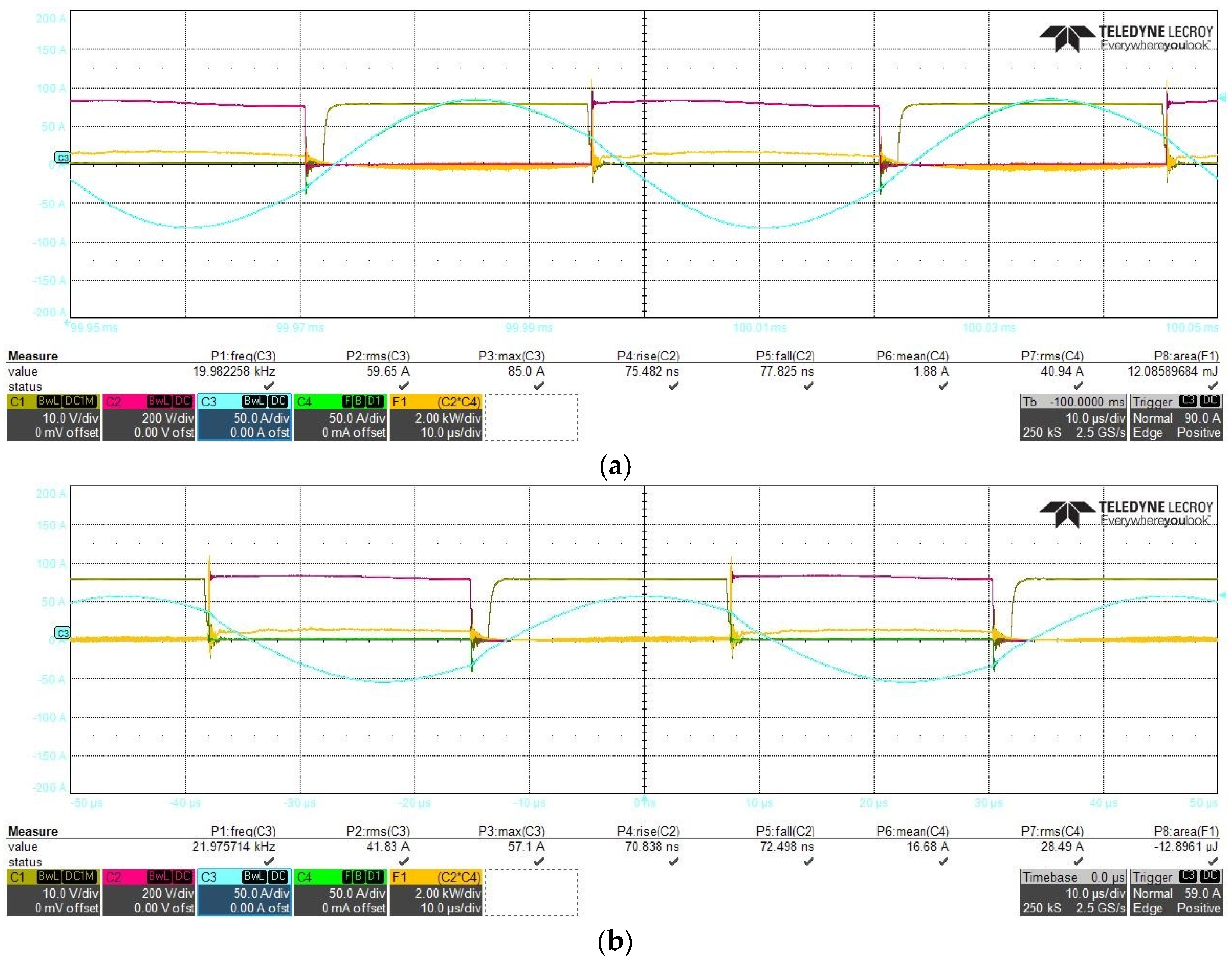
Figure 9.
IHW50N65R6 oscilloscope measurements at conventional induction cooking operations: (a) Operating condition−1 waveforms; (b) Operating condition−2 waveforms. Yellow (CH1) and red (CH2) waveforms are low and high side IGBT VCE voltages, respectively; blue waveform (CH3) is coil current; green waveform (CH4) is high side IGBT current; orange waveform (MATH2) is high side IGBT power loss.
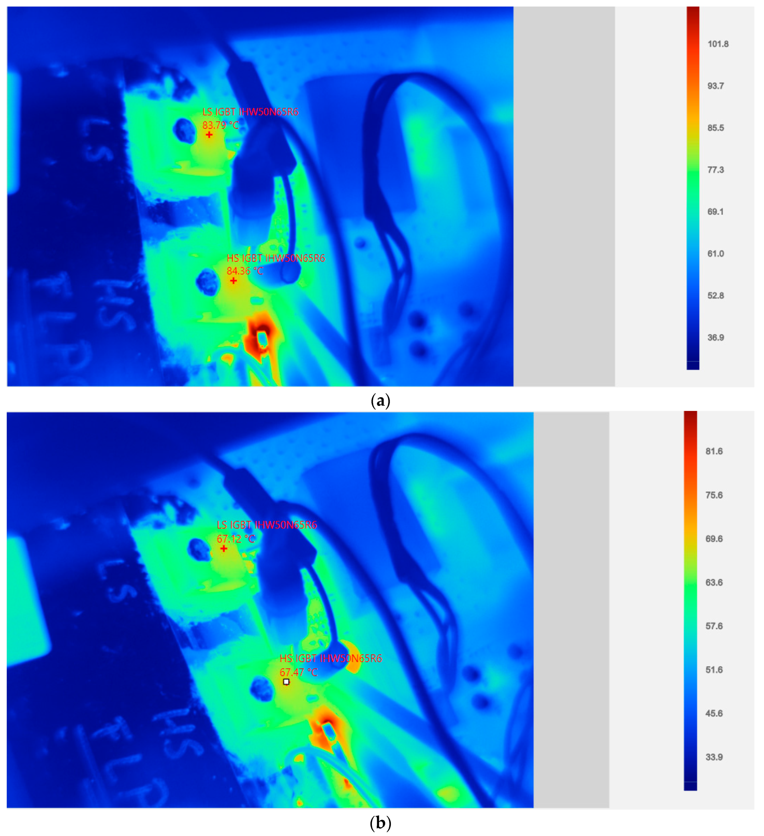
Figure 10.
IHW50N65R6 thermal measurements at conventional induction cooking operation: (a) Thermal measurements of operating condition 1; (b) Thermal measurements of operating condition 2.
Figure 10.
IHW50N65R6 thermal measurements at conventional induction cooking operation: (a) Thermal measurements of operating condition 1; (b) Thermal measurements of operating condition 2.
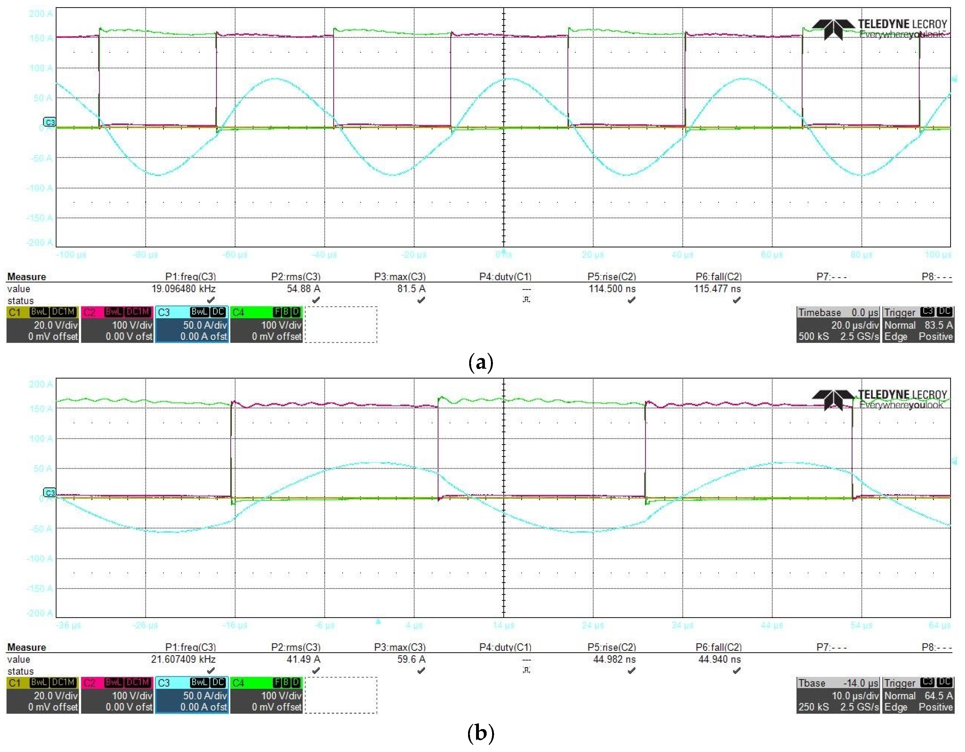
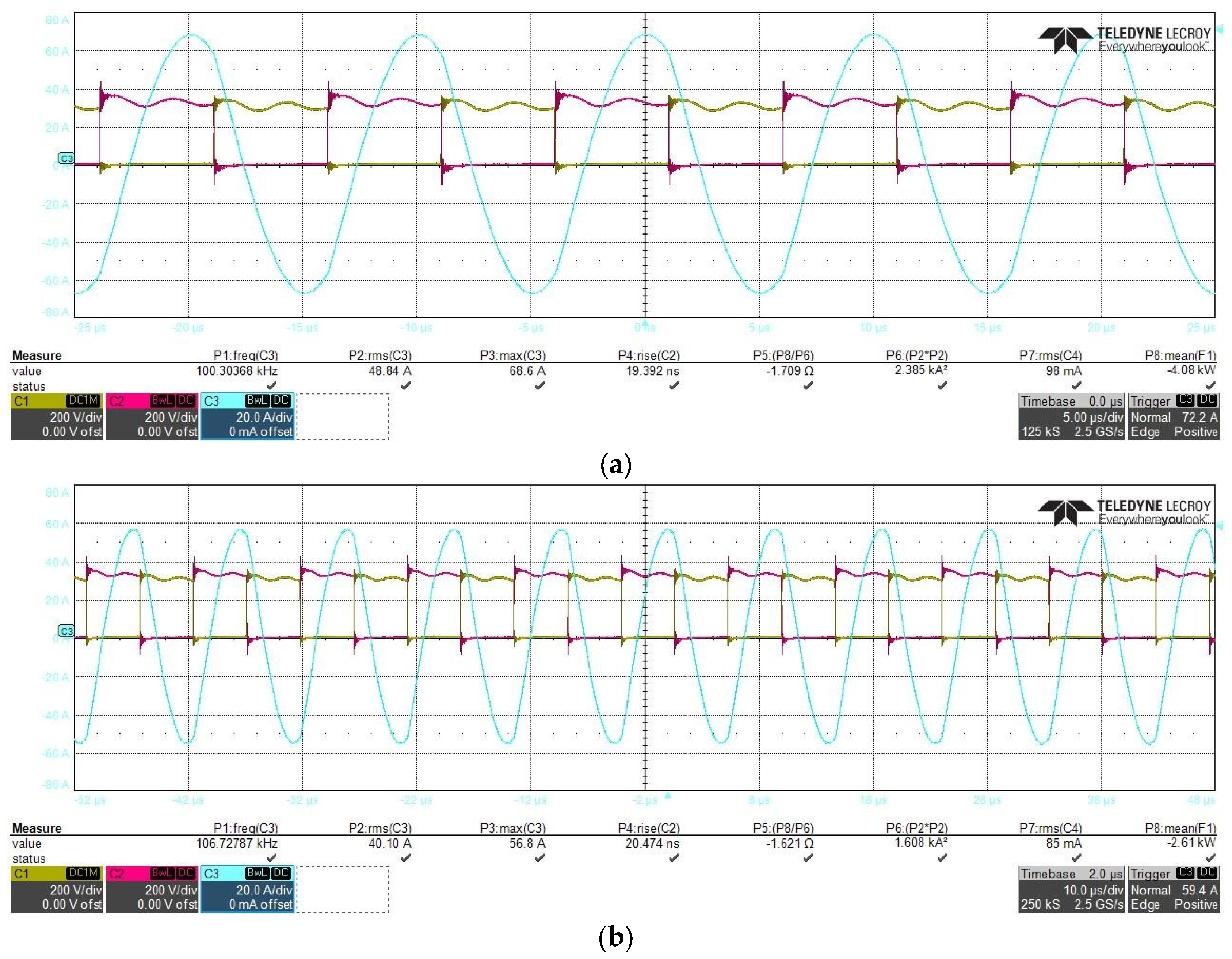
Figure 11.
GS66516B oscilloscope measurements at conventional induction cooking operation: (a) Operating condition 1 waveforms. (b) Operating condition 2 waveforms. Red (CH2) and green (CH4) waveforms are low and high side HEMTs VDS voltages, respectively; blue (CH3) waveform is coil current.
Figure 11.
GS66516B oscilloscope measurements at conventional induction cooking operation: (a) Operating condition 1 waveforms. (b) Operating condition 2 waveforms. Red (CH2) and green (CH4) waveforms are low and high side HEMTs VDS voltages, respectively; blue (CH3) waveform is coil current.
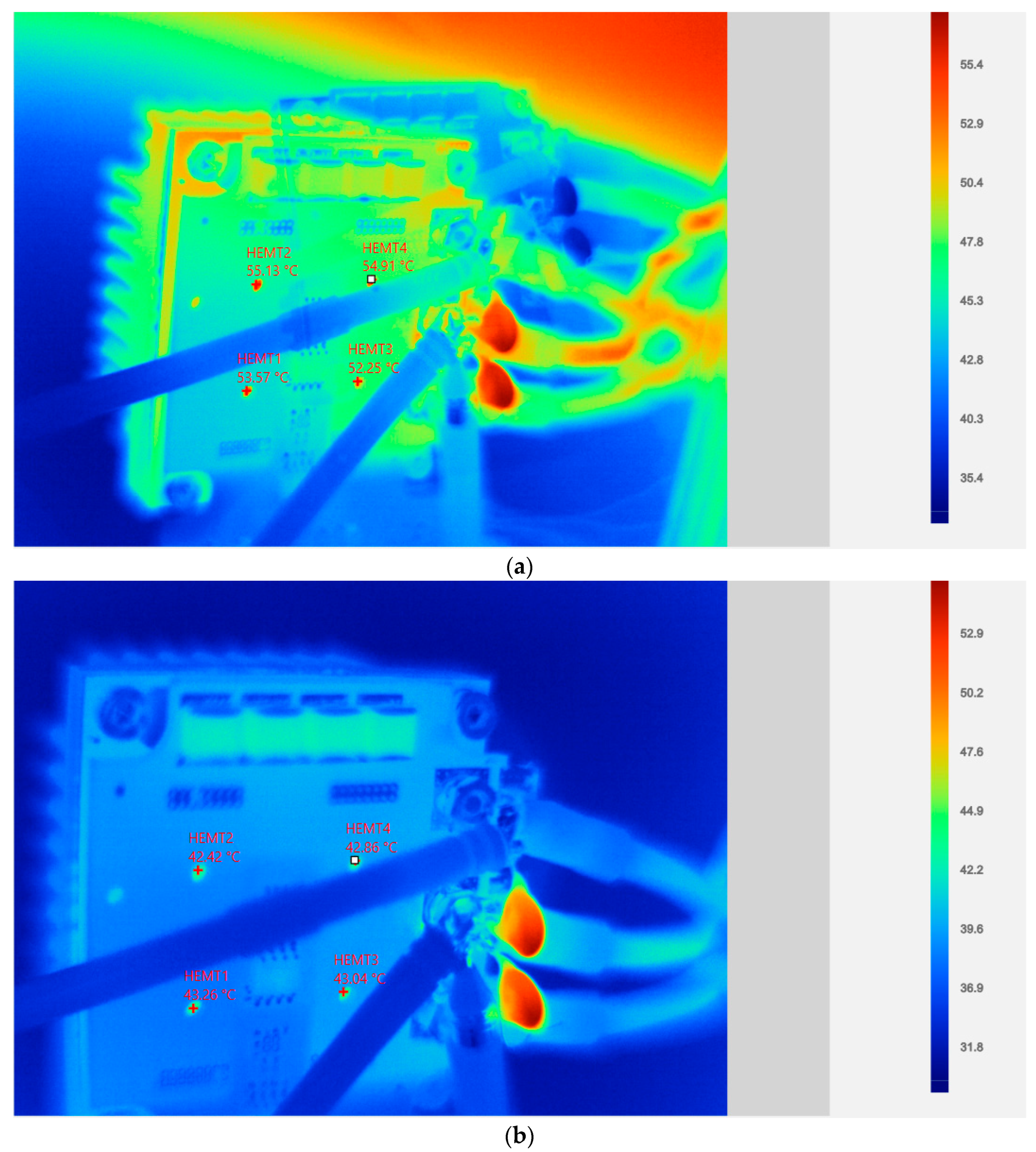
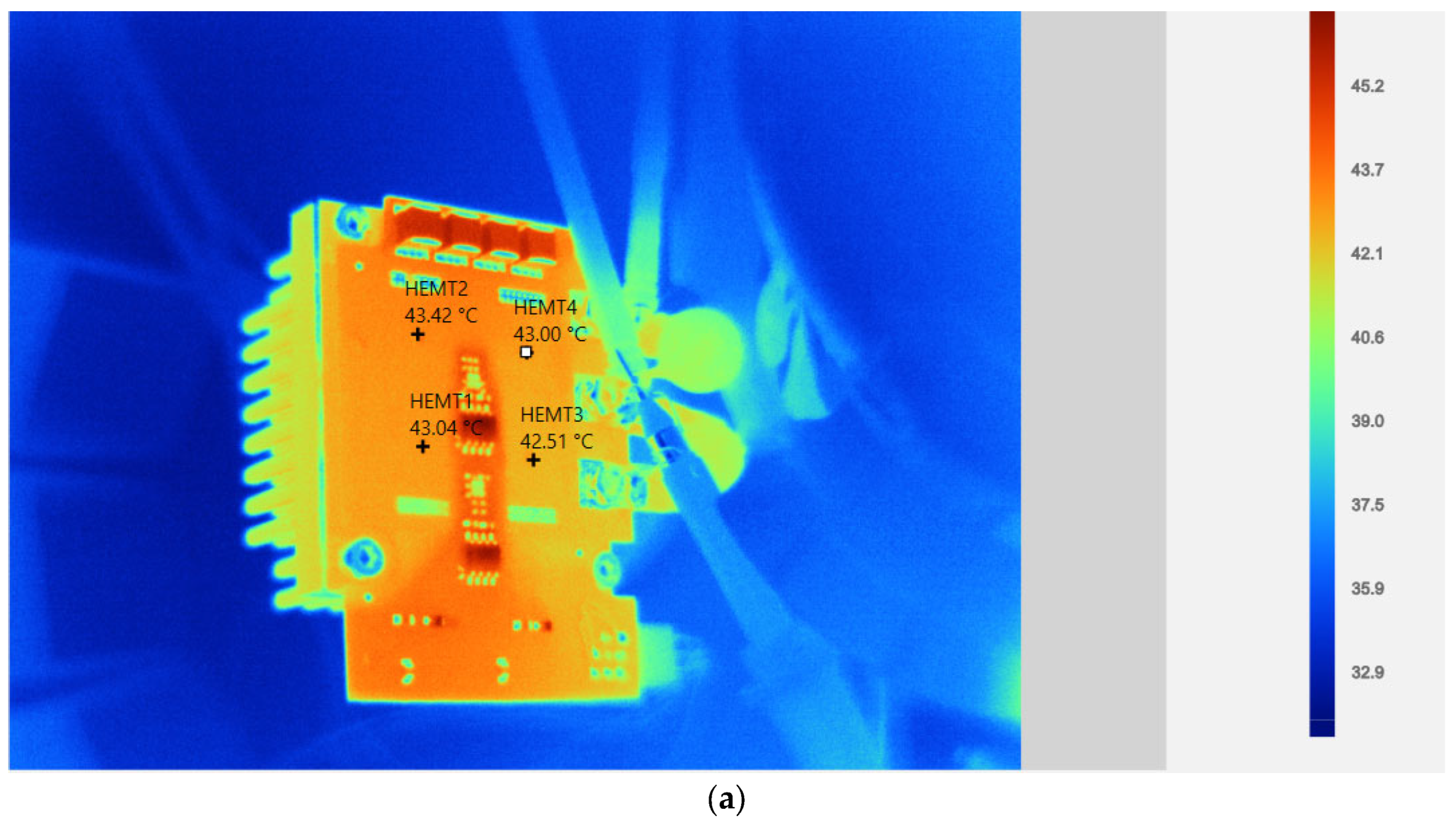
Figure 12.
GS66516B thermal measurements at conventional induction cooking operation: (a) Thermal measurements of operating condition 1; (b) Thermal measurements of operating condition 2.
Figure 12.
GS66516B thermal measurements at conventional induction cooking operation: (a) Thermal measurements of operating condition 1; (b) Thermal measurements of operating condition 2.
Figure 13.
GS66516B oscilloscope measurements at high-frequency induction cooking operation: (a) Operating condition 1 waveforms; (b) Operating condition 2 waveforms. Yellow (CH1) and red (CH2) waveforms are low and high side HEMTs VDS voltages respectively, blue (CH3) waveform is coil current.
Figure 13.
GS66516B oscilloscope measurements at high-frequency induction cooking operation: (a) Operating condition 1 waveforms; (b) Operating condition 2 waveforms. Yellow (CH1) and red (CH2) waveforms are low and high side HEMTs VDS voltages respectively, blue (CH3) waveform is coil current.
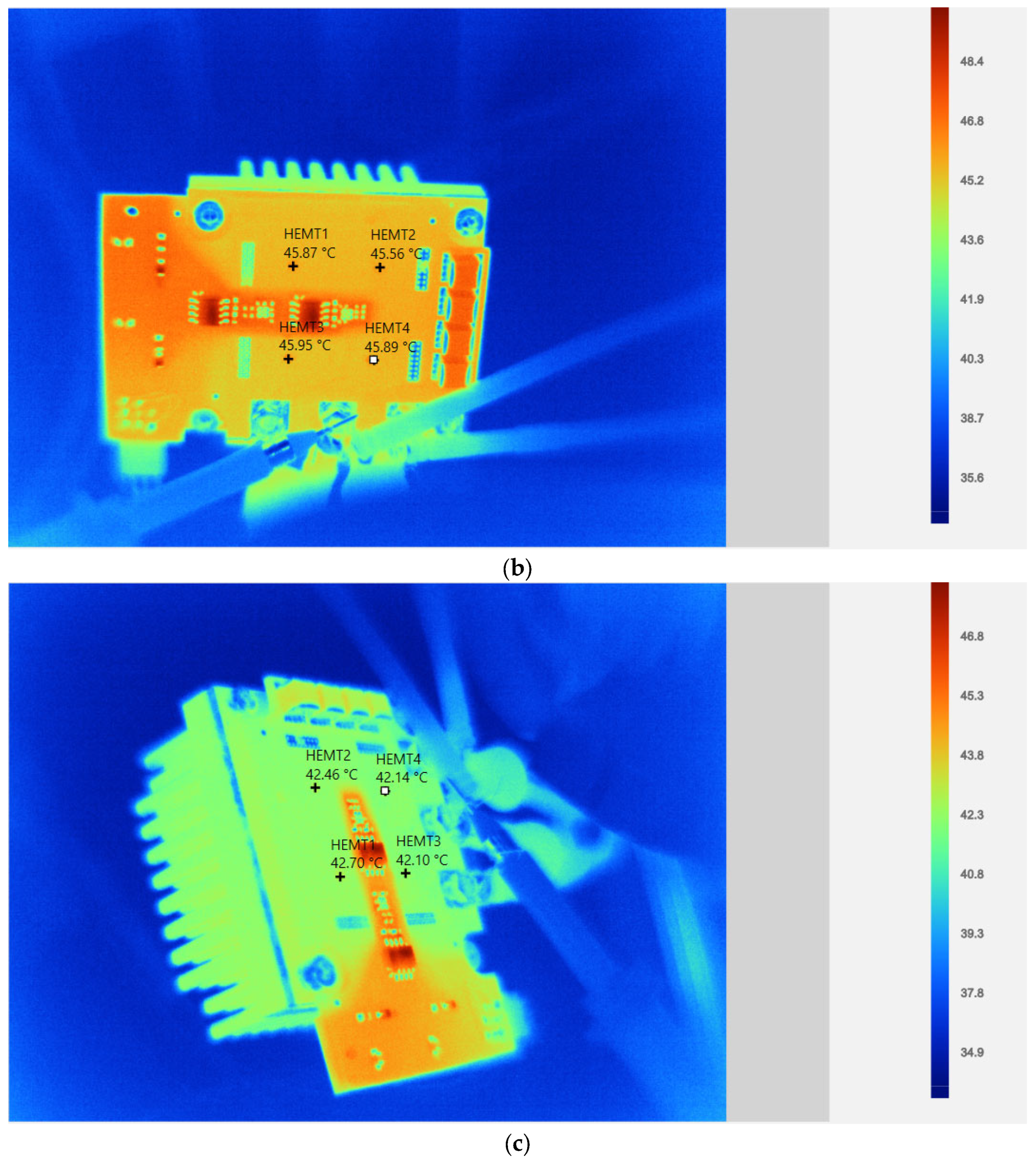
Figure 14.
GS66516B thermal measurements at high-frequency induction cooking operation: (a) Thermal measurements of operating condition 1; (b) Thermal measurements of operating condition 2.
Figure 14.
GS66516B thermal measurements at high-frequency induction cooking operation: (a) Thermal measurements of operating condition 1; (b) Thermal measurements of operating condition 2.
Figure 15.
GS66516B oscilloscope measurements at all-metal induction cooking operation: (a) Operating condition 1 waveforms; (b) Operating condition 2 waveforms. Yellow (CH1) and red (CH2) waveforms are low and high side HEMTs VDS voltages, respectively; blue (CH3) waveform is coil current.
Figure 15.
GS66516B oscilloscope measurements at all-metal induction cooking operation: (a) Operating condition 1 waveforms; (b) Operating condition 2 waveforms. Yellow (CH1) and red (CH2) waveforms are low and high side HEMTs VDS voltages, respectively; blue (CH3) waveform is coil current.
Figure 16.
GS66516B thermal measurements at all-metal induction cooking operation: (a) Thermal measurements of operating condition 1; (b) Thermal measurements of operating condition 2.
Figure 16.
GS66516B thermal measurements at all-metal induction cooking operation: (a) Thermal measurements of operating condition 1; (b) Thermal measurements of operating condition 2.
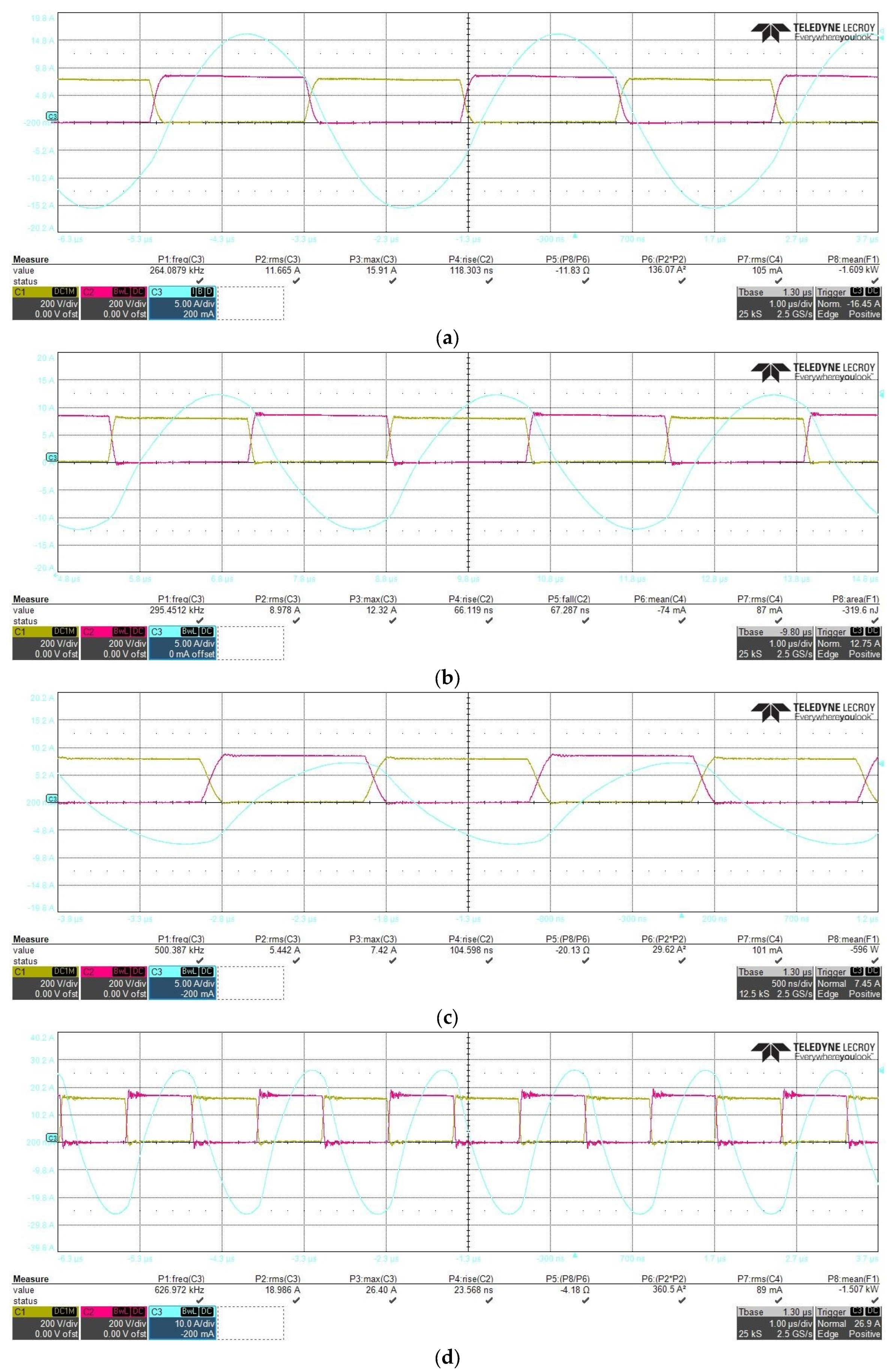
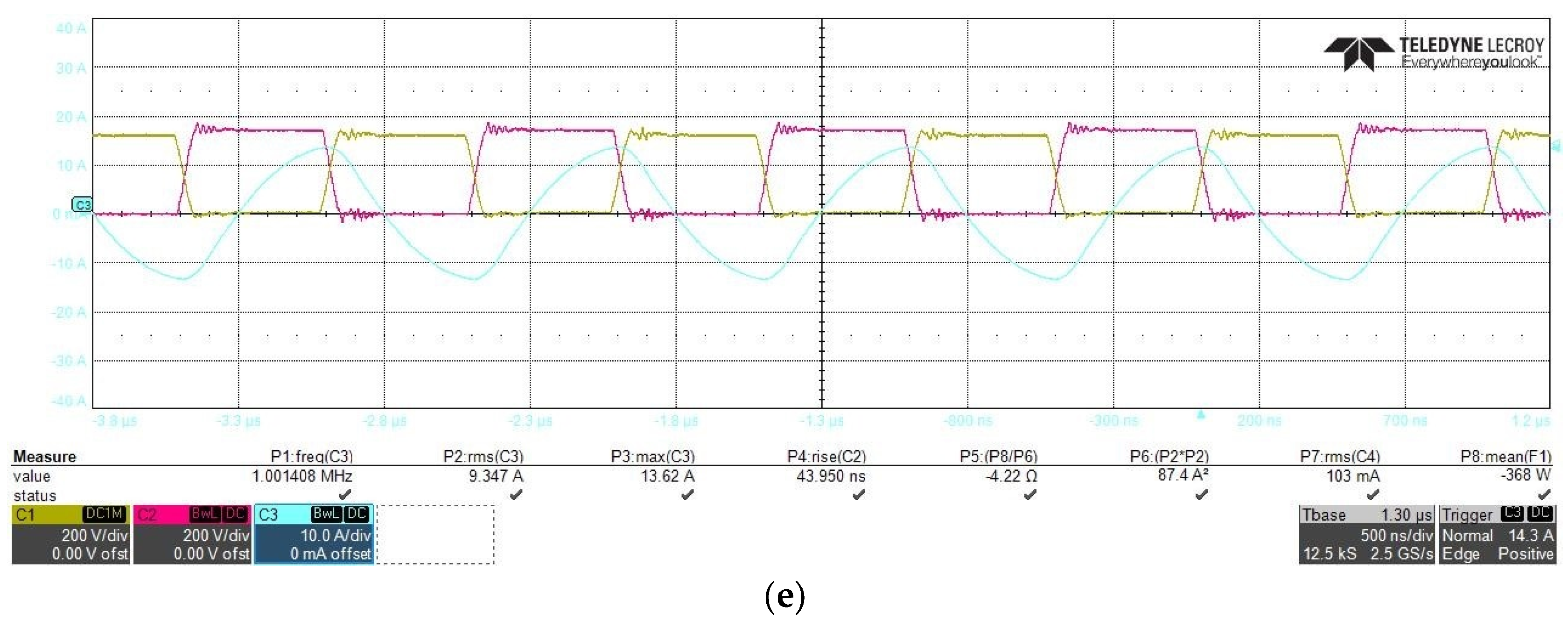
Figure 17.
GS66516B oscilloscope measurements at full-flexi induction cooking operation (a) Operating condition 1 waveforms; (b) Operating condition 2 waveforms; (c) Operating condition 3 waveforms; (d) Operating condition 4 waveforms; (e) Operating condition 5 waveforms. Yellow (CH1) and red (CH2) waveforms are low and high side HEMTs VDS voltages, respectively; blue (CH3) waveform is coil current.
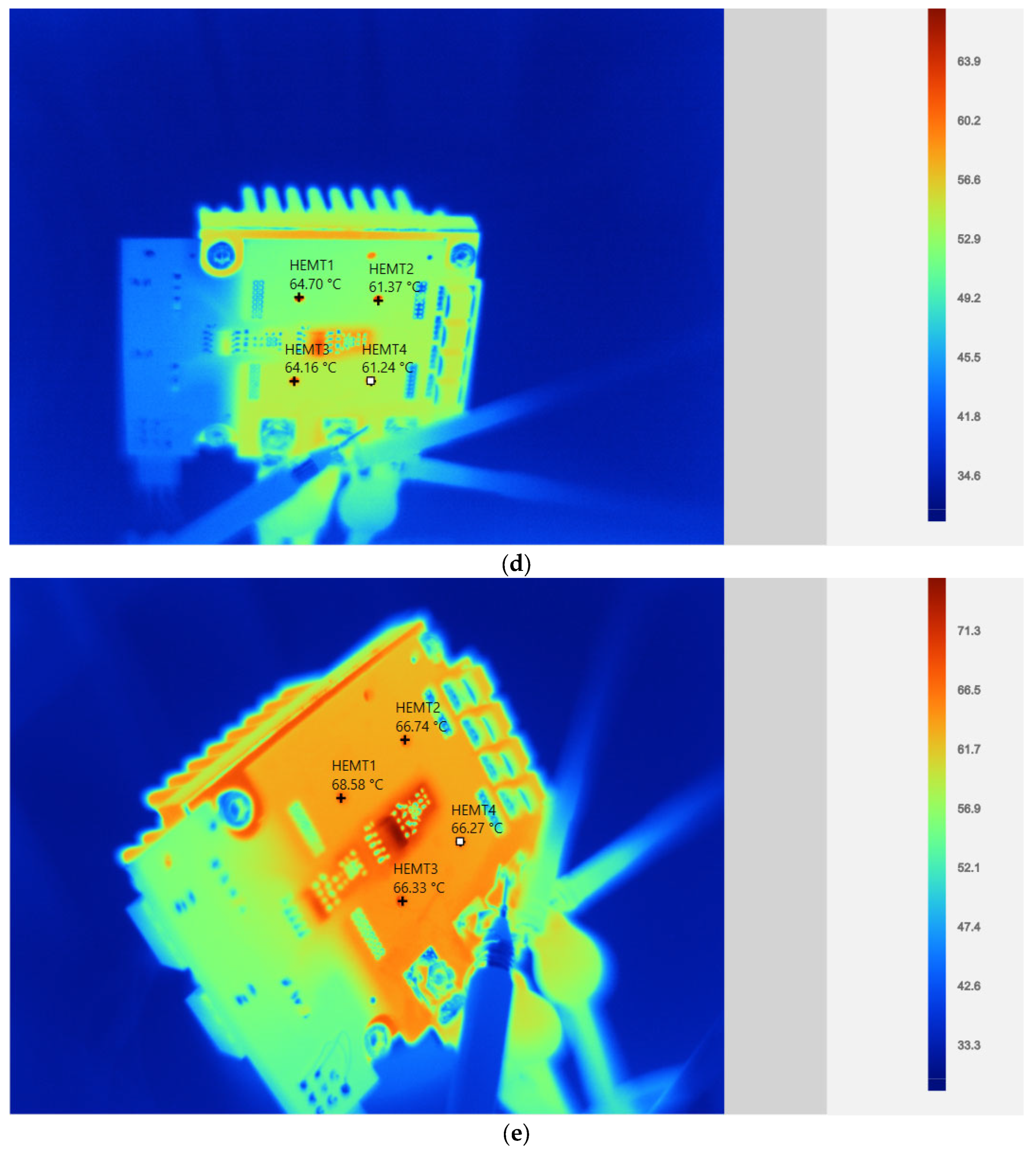
Figure 18.
GS66516B thermal measurements at full-flexi induction cooking operation: (a) Operating condition 1; (b) Operating condition 2; (c) Operating condition 3; (d) Operating condition 4; (e) Operating condition 5.
Figure 18.
GS66516B thermal measurements at full-flexi induction cooking operation: (a) Operating condition 1; (b) Operating condition 2; (c) Operating condition 3; (d) Operating condition 4; (e) Operating condition 5.
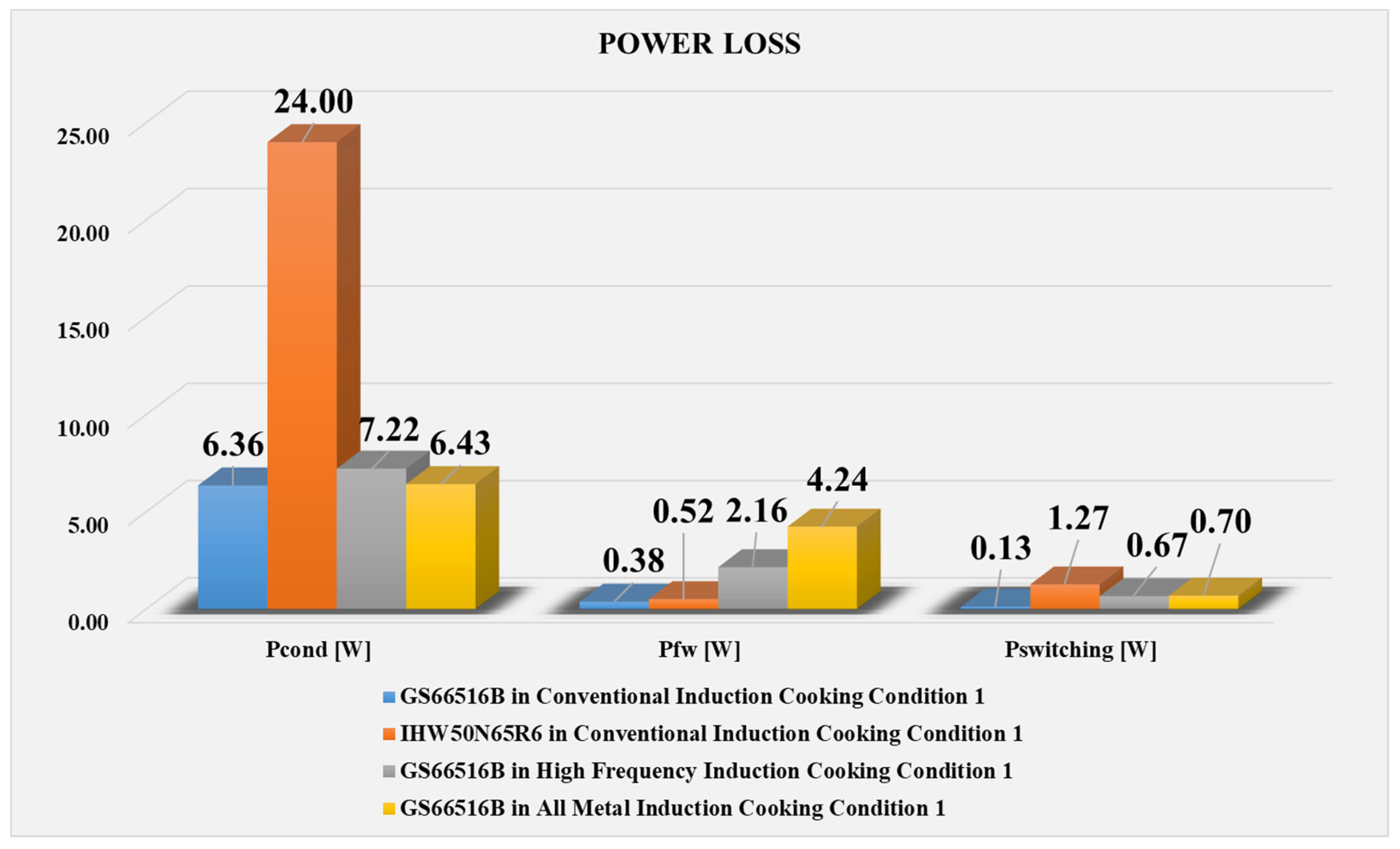
Figure 19.
All condition 1 measurements.
Figure 19.
All condition 1 measurements.
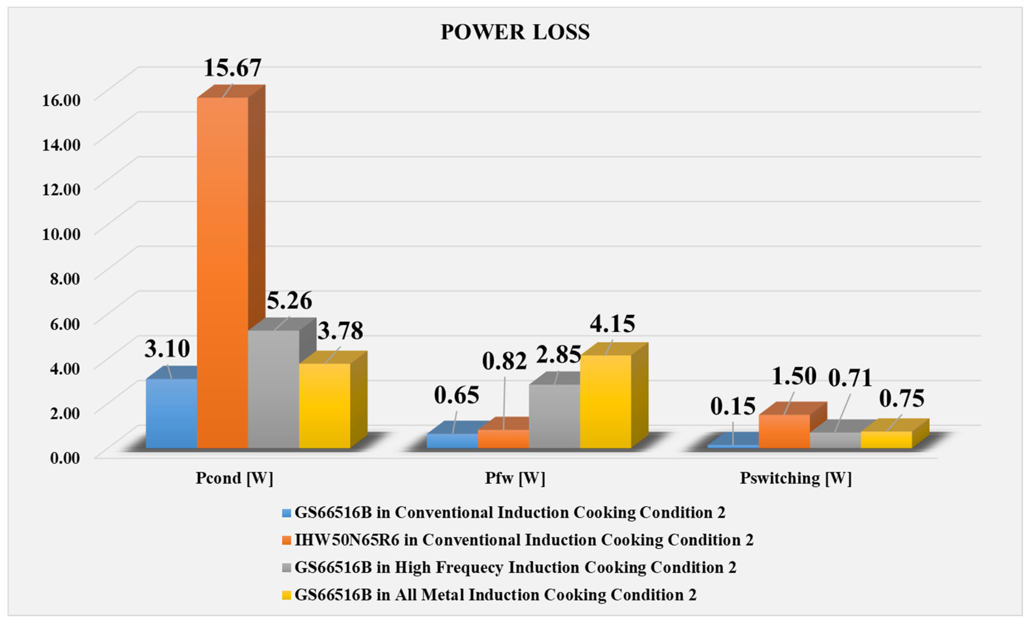
Figure 20.
All condition 2 measurements.
Figure 20.
All condition 2 measurements.
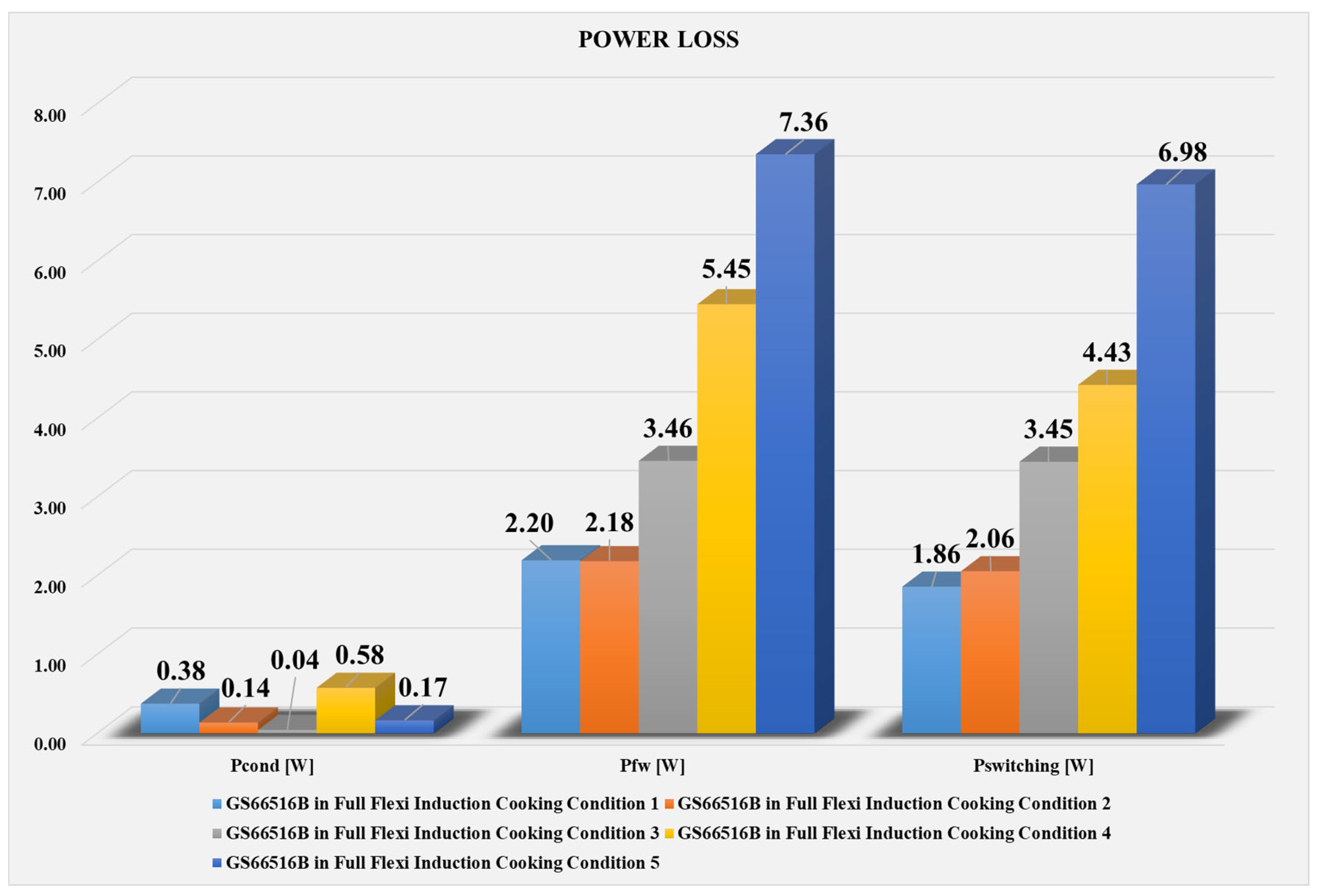
Figure 21.
All full-flexi measurements.
Figure 21.
All full-flexi measurements.
Table 1.
Operating conditions fundamental parameters.
Table 1.
Operating conditions fundamental parameters.
| Parameters | Condition-1 | Condition-2 |
|---|
| Switching frequency | 19.5 kHz | 22 kHz |
| Duty cycle | 0.5 | 0.5 |
| Dead time | 1.5 µs | 1.5 µs |
| Iturnoff | 8 A | 40 A |
| Max. coil current | 79.33 A | 58.33 A |
| RMS coil current | 37.00 A | 27.71 A |
| Max. switch current | 79.33 A | 58.33 A |
| RMS switch current | 19.17 A | 14.14 A |
| Avg. switch current | 1.96 A | 8.29 A |
| Max. diode current | 28 A | 64 A |
| RMS diode current | 0.86 A | 3.39 A |
| Avg. diode current | 0.11 A | 0.85 A |
Table 2.
Semiconductor Material Comparison.
Table 2.
Semiconductor Material Comparison.
| Feature | Unit | Si | 6H-SiC | 4H-SiC | GaN | Diamond |
|---|
| Thermal Conductivity | [W/cmK] | 1.5 | 4.9 | 4.9 | 1.3 | 22 |
| Band Gap | [eV] | 1.12 | 3.03 | 3.26 | 3.45 | 5.5 |
| Breakdown Field | [MV/cm] | 0.3 | 2.5 | 2.2 | 3.3 | 20 |
| Dielectric Constant | | 11.9 | 9.66 | 9.7 | 8.5–10.4 | 5.5 |
| Electron Mobility | [cm2/Vs] | 1500 | 400 | 800 | 2000 | 1060 |
| Drift Velocity | [107 cm/s] | 1.02 | 2.0 | 2.0 | 2.2 | 2.5 |
Table 3.
Power circuit parameters for conventional induction cooking (IHW50N65R6).
Table 3.
Power circuit parameters for conventional induction cooking (IHW50N65R6).
| | Pinput [kW] | fsw [kHz] | Req [Ω] | Leq [uH] | Cres [nF] | Csnub [nF] | tdt [μs] | Fan Level [V] |
|---|
| Cond. 1 | 3.70 | 20.00 | 2.60 | 54.00 | 2 × 680 | 2 × 2.2 | 1.50 | 5 V/(12 V) |
| Cond. 2 | 2.40 | 22.00 | 3.29 | 52.00 | 2 × 680 | 2 × 2.2 | 1.50 | 5 V/(12 V) |
Table 4.
Power losses for conventional induction cooking operation (IHW50N65R6).
Table 4.
Power losses for conventional induction cooking operation (IHW50N65R6).
| | Pcond [W] | Psw [W] | Pfw [W] |
|---|
| Cond. 1 | 24.00 | 1.27 | 0.52 |
| Cond. 2 | 15.67 | 1.50 | 0.82 |
Table 5.
Power circuit parameters for conventional induction cooking operation (GS66516B).
Table 5.
Power circuit parameters for conventional induction cooking operation (GS66516B).
| | Pinput [kW] | fsw [kHz] | Req [Ω] | Leq [uH] | Cres [nF] | Csnub [nF] | tdeadtime [μs] | Fan Level [V] |
|---|
| Cond. 1 | 3.70 | 19.00 | 2.60 | 58.00 | 2 × 680 | 2 × 2.2 | 0.50 | 5V/(12 V) |
| Cond. 2 | 2.40 | 21.50 | 3.00 | 54.00 | 2 × 680 | 2 × 2.2 | 0.50 | 5V/(12 V) |
Table 6.
Power losses for conventional induction cooking operation (GS66516B).
Table 6.
Power losses for conventional induction cooking operation (GS66516B).
| | Pcond [W] | Psw [W] | Pfw [W] |
|---|
| Cond. 1 | 6.36 | 0.13 | 0.38 |
| Cond. 2 | 3.10 | 0.15 | 0.65 |
Table 7.
Power circuit parameters for high-frequency induction cooking operation (GS66516B).
Table 7.
Power circuit parameters for high-frequency induction cooking operation (GS66516B).
| | Pinput [kW] | fsw [kHz] | Req [Ω] | Leq [uH] | Cres [nF] | Csnub [nF] | tdeadtime [μs] | Fan Level [V] |
|---|
| Cond. 1 | 3.60 | 95.00 | 2.36 | 17.00 | 2 × 94 | 2 × 2.2 | 0.50 | 5V/(12 V) |
| Cond. 2 | 2.80 | 100.00 | 2.42 | 16.50 | 2 × 94 | 2 × 2.2 | 0.50 | 5V/(12 V) |
Table 8.
Power losses for high-frequency induction cooking operations (GS66516B).
Table 8.
Power losses for high-frequency induction cooking operations (GS66516B).
| | Pcond [W] | Psw [W] | Pfw [W] |
|---|
| Cond. 1 | 7.22 | 0.67 | 2.16 |
| Cond. 2 | 5.26 | 0.71 | 2.85 |
Table 9.
Power circuit parameters for all-metal induction cooking operation (GS66516B).
Table 9.
Power circuit parameters for all-metal induction cooking operation (GS66516B).
| | Pinput [kW] | fsw [kHz] | Req [Ω] | Leq [uH] | Cres [nF] | Csnub [nF] | tdeadtime [μs] | Fan Level [V] |
|---|
| Opt. 1 | 2.30 | 100.00 | 1.87 | 17.00 | 2 × 94 | 2 × 2.2 | 0.50 | 5 V/(12 V) |
| Opt. 2 | 1.50 | 105.00 | 1.99 | 17.00 | 2 × 94 | 2 × 2.2 | 0.50 | 5 V/(12 V) |
Table 10.
Power losses for all-metal induction cooking operations (GS66516B).
Table 10.
Power losses for all-metal induction cooking operations (GS66516B).
| | Pcond [W] | Psw [W] | Pfw [W] |
|---|
| Opt. 1 | 6.43 | 0.70 | 4.24 |
| Opt. 2 | 3.78 | 0.75 | 4.15 |
Table 11.
Power circuit parameters for full-flexi induction cooking operations (GS66516B).
Table 11.
Power circuit parameters for full-flexi induction cooking operations (GS66516B).
| | Pinput [kW] | fsw [kHz] | Req [Ω] | Leq [uH] | Cres [nF] | Csnub [nF] | tdeadtime [μs] | Fan Level [V] |
|---|
| Opt. 1 | 0.87 | 265.00 | 8.53 | 20.00 | 2 × 11 | 2 × 0.470 | 0.20 | 0 V/(12 V) |
| Opt. 2 | 0.53 | 295.00 | 14.00 | 18.50 | 2 × 11 | 2 × 0.470 | 0.20 | 0 V/(12 V) |
| Opt. 3 | 0.30 | 500.00 | 20.00 | 15.00 | 2 × 11 | 2 × 0.470 | 0.20 | 5 V/(12 V) |
| Opt. 4 | 1.00 | 625.00 | 5.91 | 4.60 | 2 × 11 | 2 × 0.470 | 0.20 | 5 V/(12 V) |
| Opt. 5 | 0.40 | 1000.00 | 8.90 | 4.80 | 2× 4.7 | 2 × 0.470 | 0.20 | 5 V/(12 V) |
Table 12.
Power losses for full-flexi induction cooking operations (GS66516B).
Table 12.
Power losses for full-flexi induction cooking operations (GS66516B).
| | Pcond [W] | Psw [W] | Pfw [W] |
|---|
| Opt. 1 | 0.38 | 1.86 | 2.20 |
| Opt. 2 | 0.14 | 2.06 | 2.18 |
| Opt. 3 | 0.04 | 3.45 | 3.46 |
| Opt. 4 | 0.58 | 4.43 | 5.45 |
| Opt. 5 | 0.17 | 6.98 | 7.36 |
Table 13.
All measurements result.
Table 13.
All measurements result.
| | Pinput [kW] | fsw [kHz] | Req [Ω] | Leq [uH] | Cres [nF] | Csnub [nF] | tdt [μs] | Fan Level [V] | Pcond [W] | Psw
[W] | Pfw
[W] |
|---|
| Conventional Induction Cooking Operation (IHW50N65R6) |
| Cond. 1 | 3.70 | 20.00 | 2.60 | 54.00 | 2 × 680 | 2 × 2.2 | 1.50 | 5 V/(12 V) | 24.00 | 1.27 | 0.52 |
| Cond. 2 | 2.40 | 22.00 | 3.29 | 52.00 | 2 × 680 | 2 × 2.2 | 1.50 | 5 V/(12 V) | 15.67 | 1.50 | 0.82 |
| Conventional Induction Cooking Operation (GS66516B) |
| Cond. 1 | 3.70 | 19.00 | 2.60 | 58.00 | 2 × 680 | 2 × 2.2 | 0.50 | 5 V/(12 V) | 6.36 | 0.13 | 0.38 |
| Cond. 2 | 2.40 | 21.50 | 3.00 | 54.00 | 2 × 680 | 2 × 2.2 | 0.50 | 5 V/(12 V) | 3.10 | 0.15 | 0.65 |
| WBG for High-Frequency Induction Cooking Conditions (GS66516B) |
| Cond. 1 | 3.60 | 95.00 | 2.36 | 17.00 | 2 × 94 | 2 × 2.2 | 0.50 | 5 V/(12 V) | 7.22 | 0.67 | 2.16 |
| Cond. 2 | 2.80 | 100.00 | 2.42 | 16.50 | 2 × 94 | 2 × 2.2 | 0.50 | 5 V/(12 V) | 5.26 | 0.71 | 2.85 |
| WBG for High-Frequency Induction Cooking Conditions (GS66516B) |
| Cond. 1 | 2.30 | 100.00 | 1.87 | 17.00 | 2 × 94 | 2 × 2.2 | 0.50 | 5 V/(12 V) | 6.43 | 0.70 | 4.24 |
| Cond. 2 | 1.50 | 105.00 | 1.99 | 17.00 | 2 × 94 | 2 × 2.2 | 0.50 | 5 V/(12 V) | 3.78 | 0.75 | 4.15 |
| WBG for High-Frequency Induction Cooking Conditions (GS66516B) |
| Cond. 1 | 0.87 | 265.00 | 8.53 | 20.00 | 2 × 11 | 2 × 0.470 | 0.20 | 0 V/(12 V) | 0.38 | 1.86 | 2.20 |
| Cond. 2 | 0.53 | 295.00 | 14.00 | 18.50 | 2 × 11 | 2 × 0.470 | 0.20 | 0 V/(12 V) | 0.14 | 2.06 | 2.18 |
| Cond. 3 | 0.30 | 500.00 | 20.00 | 15.00 | 2 × 11 | 2 × 0.470 | 0.20 | 5 V/(12 V) | 0.04 | 3.45 | 3.46 |
| Cond. 4 | 1.00 | 625.00 | 5.91 | 4.60 | 2 × 11 | 2 × 0.470 | 0.20 | 5 V/(12 V) | 0.58 | 4.43 | 5.45 |
| Cond. 5 | 0.40 | 1000.00 | 8.90 | 4.80 | 2 × 4.7 | 2 × 0.470 | 0.20 | 5 V/(12 V) | 0.17 | 6.98 | 7.36 |


