
Design of Viscosity and Nozzle Path Using Food 3D Printer and Pneumatic Pressure Syringe-Type Dispensing System


Abstract
:1. Introduction
2. Hardware Settings
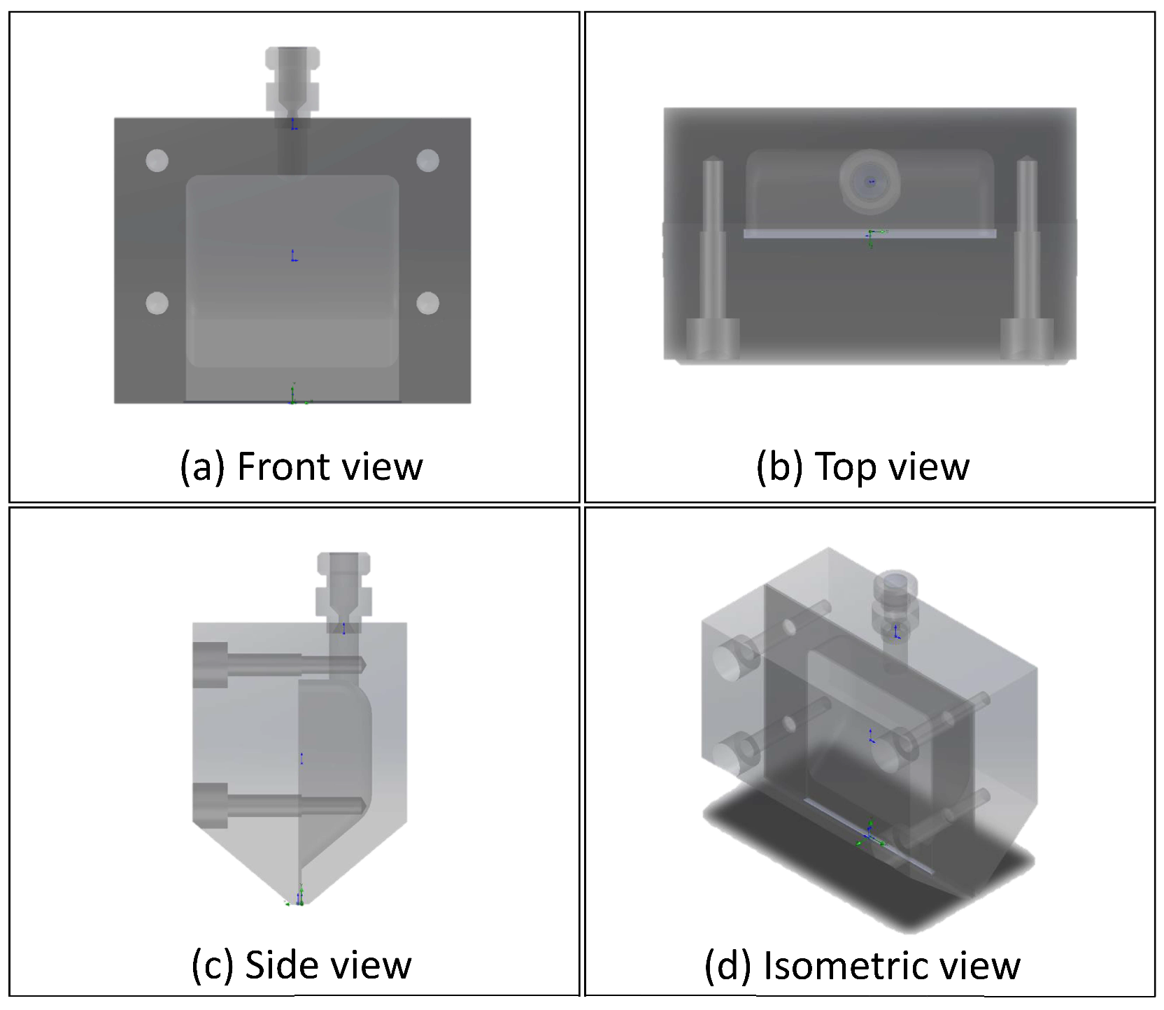
2.1. Nozzle Design of Food 3D Printer
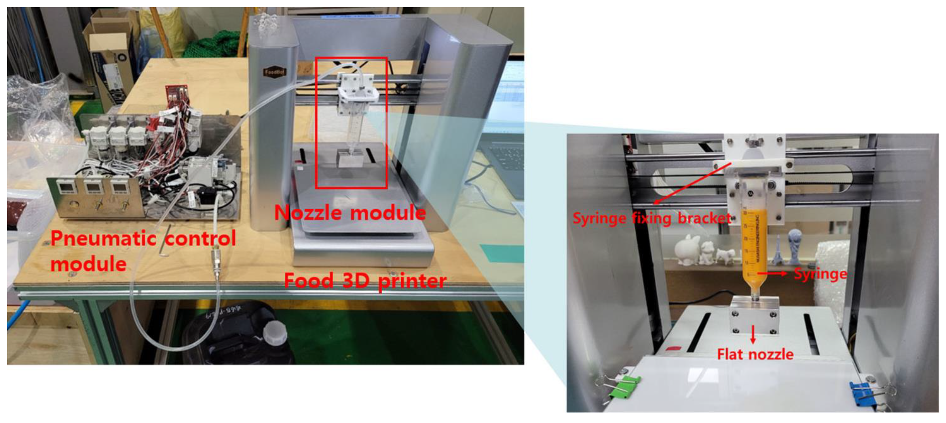
2.2. Food 3D Printer and Syringe Dispensing System
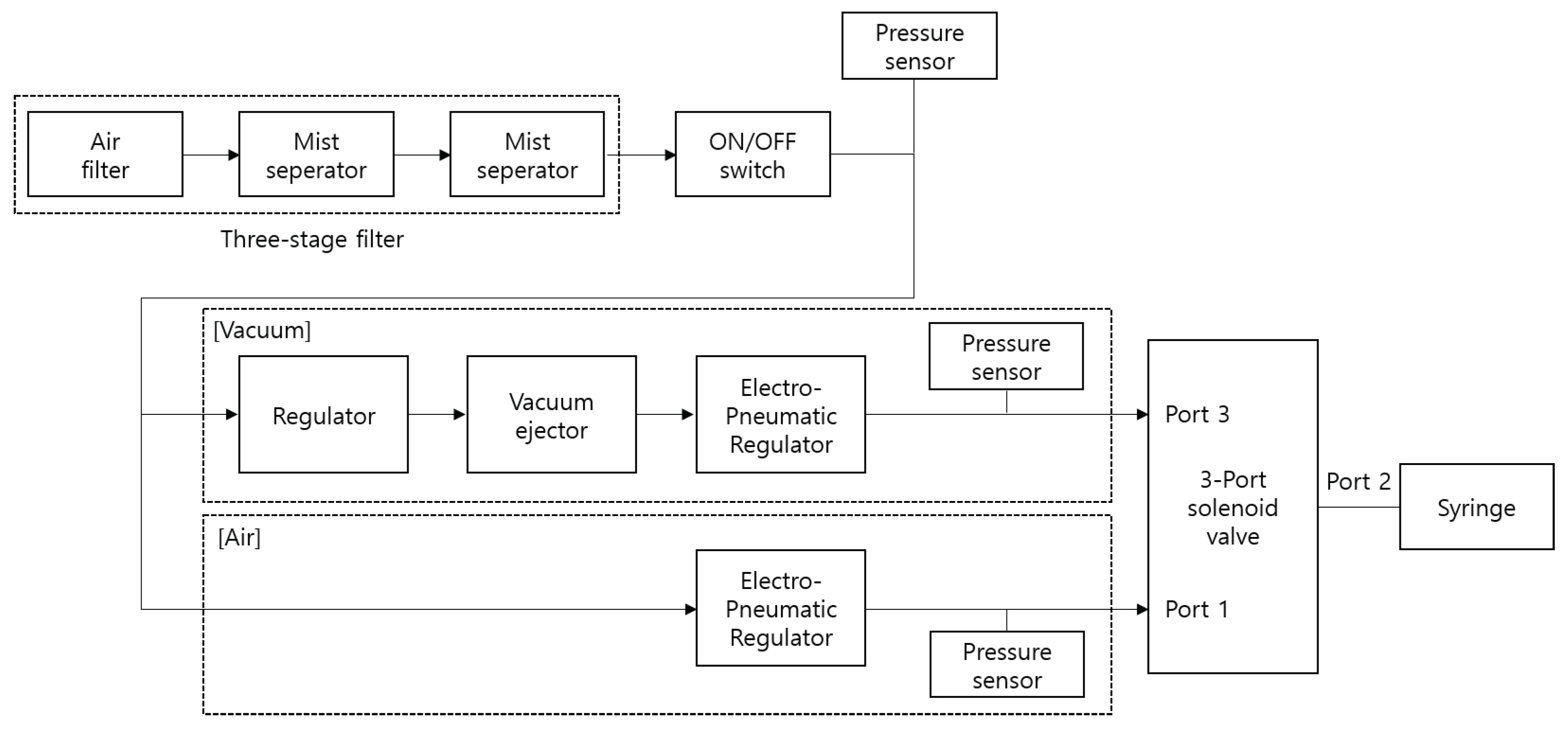
2.3. Pneumatic Control Module
3. Methodology
3.1. Experiment Pre-Settings
3.1.1. Parameter Settings of Food 3D Printer
3.1.2. CoQ10 Manufacturing
3.2. Experimental Procedure
3.2.1. Simulation Environment
3.2.2. Test Environment
4. Results and Discussion
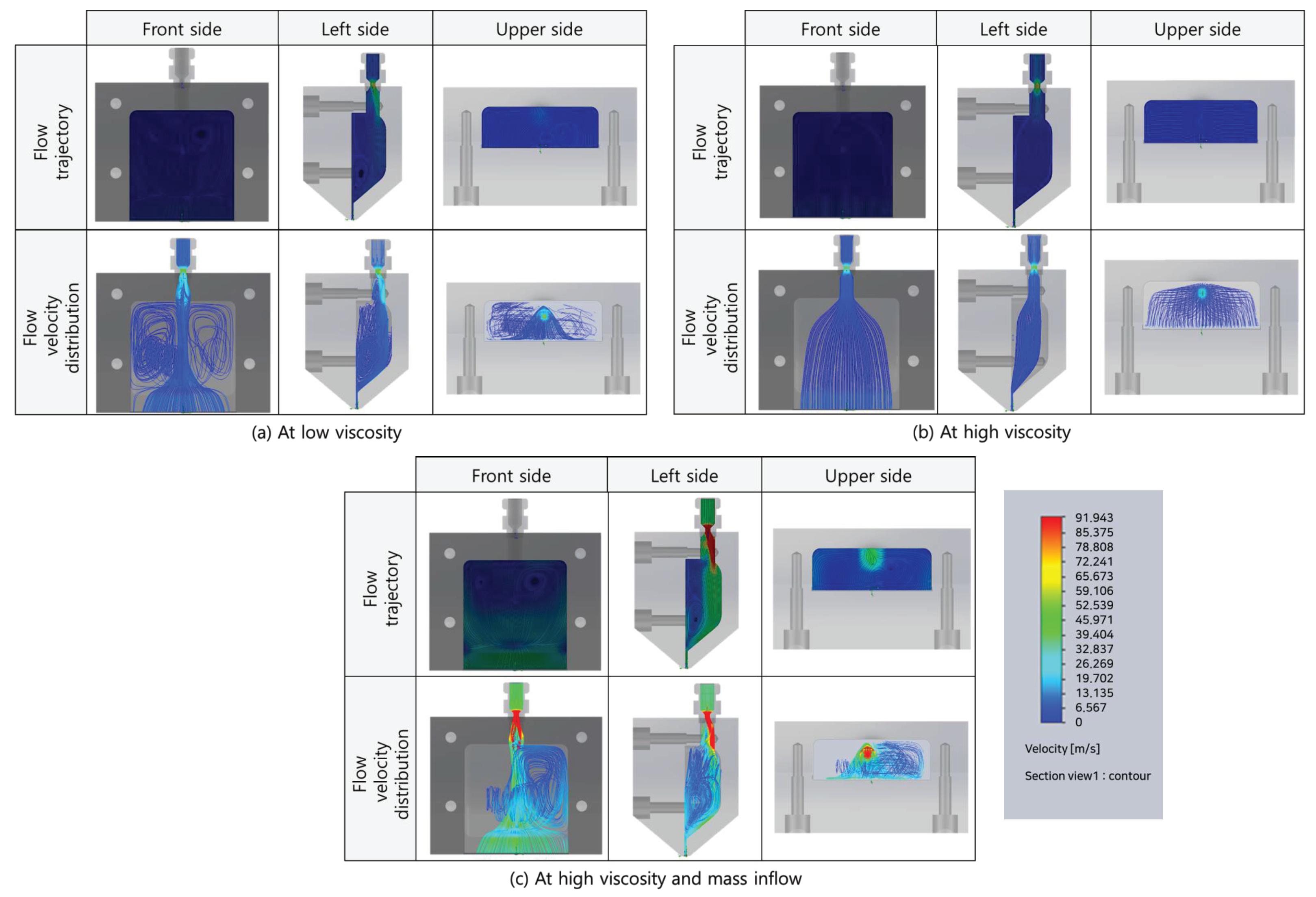
4.1. Flow Analysis of Viscosity Conditions in Simulation
4.1.1. Low Viscosity Condition
4.1.2. High Viscosity Condition
4.1.3. High Viscosity and Mass Inflow Conditions
4.2. ODF Results according to Viscosity Conditions
4.3. ODF Results according to Path Design of Food 3D Printer
5. Conclusions
Author Contributions
Funding
Institutional Review Board Statement
Informed Consent Statement
Data Availability Statement
Conflicts of Interest
Abbreviations
| UV | Ultraviolet |
| SLA | Stereolithography |
Appendix A

| Path | No. | G-Code | Variable | Command | Explanation |
|---|---|---|---|---|---|
| 1 | 1 | M92 E1067 | “M92 E”, | Ready to start printing (No movement) | |
| 2 | G21 | ||||
| 3 | G90 | ||||
| 4 | M82 | ||||
| 2 | 5 | G28 X0 Y0 | XY-axis home position | ||
| 3 | 6 | G28 Z0 | Z-axis home position | ||
| 4 | 7 | G1 Z38 F3000 | “G1 Z”, ( + ), “F3000” | Z-axis movement (Ready for output) | |
| 5 | 8 | G1 F9000 X100 | “G1 F9000 X”, | X-axis movement (Ready for output) | |
| 6 | 9 | G92 E0 | Ready for extruder output (No movement) | ||
| 10 | G1 F300 E4.5 | ||||
| 11 | G92 E0 | ||||
| 12 | G1 F3000 E-2 | “G1 F3000 E”, | |||
| 7 | 13 | G1 Y115 | “G1 Y”, | Move to Y-axis output position | |
| 8 | 14 | G0 F4800 Z28.5 | “G0 F4800 Z”, | Z-axis movement (Print thickness position) | |
| 9 | 15 | G1 F3000 E0.0 | Prepare the extruder (No movement) | ||
| 16 | G1 F900 E0.00017 | “G1 F”, , “E”, E1 | |||
| 10 | 17 | G1 Y85 E0.032 | “G1 Y”, , “E”, | Discharge movement as much as Y-axis output length | |
| 11 | 18 | G1 F3000 E-1.968 | “G1 F3000 E”, | Extruder retreat (No movement) | |
| 12 | 19 | G0 F4800 Z38 | G0 F4800 Z”, | Z-axis movement upward as much as Z + 10 after dispensing is completed | |
| 13 | 20 | G28 Y0 | Y-axis home position | ||
| 14 | 21 | G91 G1 E-3 F300 | Exit after completion of output (No movement) | ||
| 22 | M84 | ||||
| 23 | G90 |
Appendix B
| Path | No. | G-Code | Variable | Command | Explanation |
|---|---|---|---|---|---|
| 1 | 1 | M92 E1067 | “M92 E”, | Ready to start printing (No movement) | |
| 2 | G21 | ||||
| 3 | G90 | ||||
| 4 | M82 | ||||
| 2 | 5 | G28 X0 Y0 | XY-axis home position | ||
| 3 | 6 | G28 Z0 | Z-axis home position | ||
| 4 | 7 | G1 Z38 F3000 | “G1 Z”, , “F3000“ | Z-axis movement (Ready for output) | |
| 5 | 8 | G1 F9000 X100 | “G1 F9000 X”, | X-axis movement (Ready for output) | |
| 6 | 9 | G92 E0 | Ready for extruder output (No movement) | ||
| 10 | G1 F300 E4.5 | ||||
| 11 | G92 E0 | ||||
| 12 | G1 F3000 E-2 | “G1 F3000 E”, | |||
| 7 | 13 | G1 Y115 | “G1 Y”, | Move to Y-axis output position | |
| 8 | 14 | G0 F4800 Z28.5 | “G0 F4800 Z”, | Z-axis movement (Print thickness position) | |
| 9 | 15 | G1 F3000 E0.0 | Prepare the extruder (No movement) | ||
| 16 | G1 F900 E0.00017 | “G1 F”, , “E”, | |||
| 10 | 17 | G1 Y85 E0.032 | “G1 Y”, , “E”, | Discharge movement as much as Y-axis output length | |
| 11 | 18 | G1 F3000 E-1.968 | “G1 F3000 E”, | Extruder retreat (No movement) | |
| 12 | 19 | G0 F14400 Y75 Z38 | G0 F14400 Y”, , “Z”, | Z-axis movement, Y + 10, Z + 10, move up after dispensing is completed | |
| 13 | 20 | G0 F4800 X140 | “G0 F4800 X”, | X-axis output avoidance movement | |
| 14 | 21 | G28 Y0 | Y-axis home position | ||
| 15 | 22 | G91 G1 E-3 F300 | Exit after completion of output (No movement) | ||
| 23 | M84 | ||||
| 24 | G90 |
Appendix C
| Path | No. | G-Code | Variable | Command | Explanation |
|---|---|---|---|---|---|
| 1 | 1 | M92 E1067 | “M92 E”, | Ready to start printing (No movement) | |
| 2 | G21 | ||||
| 3 | G90 | ||||
| 4 | M82 | ||||
| 2 | 5 | G28 X0 Y0 | XY-axis home position | ||
| 3 | 6 | G28 Z0 | Z-axis home position | ||
| 4 | 7 | G1 Z38 F3000 | “G1 Z”, , “F3000“ | Z-axis movement (Ready for output) | |
| 5 | 8 | G1 F9000 X100 | “G1 F9000 X”, | X-axis movement (Ready for output) | |
| 6 | 9 | G92 E0 | Ready for extruder output (No movement) | ||
| 10 | G1 F300 E4.5 | ||||
| 11 | G92 E0 | ||||
| 12 | G1 F3000 E-2 | “G1 F3000 E”, | |||
| 7 | 13 | G1 Y115 | “G1 Y”, | Move to Y-axis output position | |
| 8 | 14 | G0 F4800 Z28.5 | “G0 F4800 Z”, | Z-axis movement (Print thickness position) | |
| 9 | 15 | G1 F3000 E0.0 | Prepare the extruder (No movement) | ||
| 16 | G1 F900 E0.00017 | “G1 F”, , “E”, | |||
| 10 | 17 | G1 Y85 E0.032 | “G1 Y”, , “E”, | Discharge movement as much as Y-axis output length | |
| 11 | 18 | G1 F3000 E-1.968 | “G1 F3000 E”, | Extruder retreat (No movement) | |
| 12 | 19 | G1 Z28 | “G1 Z”, | Z-axis movement and nozzle, base plate spacing 0 | |
| 13 | 20 | G0 F4800 Y65 | “G0 F4800 Y”, | Move Y-axis by 20 | |
| 14 | 21 | G0 X140 Z38 | “G0 X”, , “Z”, | Avoid XZ-axis simultaneous movement output | |
| 15 | 22 | G28 Y0 | Y-axis home position | ||
| 16 | 23 | G91 G1 E-3 F300 | Exit after completion of output (No movement) | ||
| 24 | M84 | ||||
| 25 | G90 |
Appendix D
| Path | No. | G-Code | Variable | Command | Explanation |
|---|---|---|---|---|---|
| 1 | 1 | M92 E1067 | “M92 E”, | Ready to start printing (No movement) | |
| 2 | G21 | ||||
| 3 | G90 | ||||
| 4 | M82 | ||||
| 2 | 5 | G28 X0 Y0 | XY-axis home position | ||
| 3 | 6 | G28 Z0 | Z-axis home position | ||
| 4 | 7 | G1 Z38 F3000 | “G1 Z”, , “F3000“ | Z-axis movement (Ready for output) | |
| 5 | 8 | G1 F9000 X100 | “G1 F9000 X”, | X-axis movement (Ready for output) | |
| 6 | 9 | G92 E0 | Ready for extruder output (No movement) | ||
| 10 | G1 F300 E4.5 | ||||
| 11 | G92 E0 | ||||
| 12 | G1 F3000 E-2 | “G1 F3000 E”, | |||
| 7 | 13 | G1 Y115 | “G1 Y”, | Move to Y-axis output position | |
| 8 | 14 | G0 F4800 Z28.5 | “G0 F4800 Z”, | Z-axis movement (Print thickness position) | |
| 9 | 15 | G1 F3000 E0.0 | Prepare the extruder (No movement) | ||
| 16 | G1 F900 E0.00017 | “G1 F”, , “E”, | |||
| 10 | 17 | G1 Y85 E0.032 | “G1 Y”, , “E”, | Discharge movement as much as Y-axis output length | |
| 11 | 18 | G1 F3000 E-1.968 | “G1 F3000 E”, | Extruder retreat (No movement) | |
| 12 | 19 | G1 F9000 Z27.95 | “G1 Z”, | Tuning work with Z-axis movement and nozzle, bottom plate spacing −0.05 | |
| 13 | 20 | G0 F4800 Y65 | “G0 F4800 Y”, | Move Y-axis by 20 | |
| 14 | 21 | G0 X140 Z38 | “G0 X”, , “Z”, | Avoid XZ-axis simultaneous movement output | |
| 15 | 22 | G28 Y0 | Y-axis home position | ||
| 16 | 23 | G91 G1 E-3 F300 | Exit after completion of output (No movement) | ||
| 24 | M84 | ||||
| 25 | G90 |
References
- Pallottino, F.; Hakola, L.; Costa, C.; Antonucci, F.; Figorilli, S.; Seisto, A.; Menesatti, P. Printing on food or food printing: A review. Food Bioprocess Technol. 2016, 9, 725–733. [Google Scholar] [CrossRef]
- Yang, F.; Zhang, M.; Bhandari, B. Recent development in 3D food printing. Crit. Rev. Food Sci. Nutr. 2017, 57, 3145–3153. [Google Scholar] [CrossRef] [PubMed]
- Dankar, I.; Haddarah, A.; Omar, F.E.; Sepulcre, F.; Pujolà, M. 3D printing technology: The new era for food customization and elaboration. Trends Food Sci. Technol. 2018, 75, 231–242. [Google Scholar] [CrossRef]
- In, J.; Jeong, H.; Min, S.C. Material requirements for printing cookie dough using a fused deposition modeling 3D printer. Food Sci. Biotechnol. 2022, 31, 807–817. [Google Scholar] [CrossRef]
- Martirosyan, D.M.; Singh, J. A new definition of functional food by FFC: What makes a new definition unique? Funct. Foods Health Dis. 2015, 5, 209–223. [Google Scholar] [CrossRef]
- Salawi, A. An insight into preparatory methods and characterization of orodispersible film—A review. Pharmaceuticals 2022, 15, 844. [Google Scholar] [CrossRef] [PubMed]
- Hoffmann, E.M.; Breitenbach, A.; Breitkreutz, J. Advances in orodispersible films for drug delivery. Expert Opin. Drug Deliv. 2011, 8, 299–316. [Google Scholar] [CrossRef]
- Lee, G.W.; Jeong, H. Development and evaluation of orodispersible films for oro-mucosal application. Rev. Korea Contents Assoc. 2016, 14, 47–54. [Google Scholar]
- Dong, J.; Li, Y.; Lin, P.; Leeflang, M.; Van Asperen, S.; Yu, K.; Tümer, N.; Norder, B.; Zadpoor, A.; Zhou, J. Solvent-cast 3D printing of magnesium scaffolds. Acta Biomater. 2020, 114, 497–514. [Google Scholar] [CrossRef]
- Juluru, N.S. Fast dissolving oral films: A review. IJAPBC 2013, 2, 108–112. [Google Scholar]
- Mishra, R.; Amin, A. Manufacturing techniques of orally dissolving films. Pharm. Technol. 2011, 35, 70–73. [Google Scholar]
- Liu, Y.; Liang, X.; Saeed, A.; Lan, W.; Qin, W. Properties of 3D printed dough and optimization of printing parameters. Innov. Food Sci. Emerg. Technol. 2019, 54, 9–18. [Google Scholar] [CrossRef]
- Vancauwenberghe, V.; Verboven, P.; Lammertyn, J.; Nicolaï, B. Development of a coaxial extrusion deposition for 3D printing of customizable pectin-based food simulant. J. Food Eng. 2018, 225, 42–52. [Google Scholar] [CrossRef]
- Tan, C.; Toh, W.Y.; Wong, G.; Li, L. Extrusion-based 3D food printing—Materials and machines. Int. J. Bioprint. 2018, 4, 143. [Google Scholar] [CrossRef] [PubMed]
- Godoi, F.C.; Prakash, S.; Bhandari, B.R. 3d printing technologies applied for food design: Status and prospects. J. Food Eng. 2016, 179, 44–54. [Google Scholar] [CrossRef]
- Chen, D.X. Extrusion bioprinting of scaffolds. In Extrusion Bioprinting of Scaffolds for Tissue Engineering Applications; Springer: Cham, Switzerland, 2019; pp. 117–145. [Google Scholar]
- Liu, Z.; Zhang, M.; Bhandari, B.; Wang, Y. 3D printing: Printing precision and application in food sector. Trends Food Sci. Technol. 2017, 69, 83–94. [Google Scholar] [CrossRef]
- Sun, J.; Peng, Z.; Zhou, W.; Fuh, J.Y.; Hong, G.S.; Chiu, A. A review on 3D printing for customized food fabrication. Procedia Manuf. 2015, 1, 308–319. [Google Scholar] [CrossRef]
- Portanguen, S.; Tournayre, P.; Sicard, J.; Astruc, T.; Mirade, P.S. Toward the design of functional foods and biobased products by 3D printing: A review. Trends Food Sci. Technol. 2019, 86, 188–198. [Google Scholar] [CrossRef]
- Kewuyemi, Y.O.; Kesa, H.; Adebo, O.A. Trends in functional food development with three-dimensional (3D) food printing technology: Prospects for value-added traditionally processed food products. Crit. Rev. Food Sci. Nutr. 2021, 62, 7866–7904. [Google Scholar] [CrossRef]
- Jeong, H.J.; Nam, H.; Jang, J.; Lee, S.J. 3D bioprinting strategies for the regeneration of functional tubular tissues and organs. Bioengineering 2020, 7, 32. [Google Scholar] [CrossRef]
- Guo, C.; Zhang, M.; Bhandari, B. Model building and slicing in food 3D printing processes: A review. Compr. Rev. Food Sci. Food Saf. 2019, 18, 1052–1069. [Google Scholar] [CrossRef] [PubMed]
- Lanaro, M.; Forrestal, D.P.; Scheurer, S.; Slinger, D.J.; Liao, S.; Powell, S.K.; Woodruff, M.A. 3D printing complex chocolate objects: Platform design, optimization and evaluation. J. Food Eng. 2017, 215, 13–22. [Google Scholar] [CrossRef]
- Karyappa, R.; Hashimoto, M. Chocolate-based ink three-dimensional printing (Ci3DP). Sci. Rep. 2019, 9, 14178. [Google Scholar] [CrossRef] [PubMed]
| No. | Parameter | Variable | Explanation | Value |
|---|---|---|---|---|
| 1 | Offset | Extra height when moving the nozzle | 10 | |
| 2 | Offset of glass bed device | 28 | ||
| 3 | Thickness | Output thickness | 0.5 | |
| 4 | Speed | V | Output speed (mm/s) | 15 |
| 5 | Length | W | Output length | 30 |
| 6 | Location | Center X position of printout | 100 | |
| 7 | Center Y position of printout | 100 | ||
| 8 | Extrusion | E-steps per unit | 1067 | |
| 9 | Retraction size | −2 | ||
| 10 | Ready for output E position | 0.00017 | ||
| 11 | E position after output | 0.032 |
| Material Name | Material Information | Based on 1 Sheet of ODF | |
|---|---|---|---|
| Amount (mg) | Ratio (%) | ||
| CoQ10 | Functional | 100.00 | 31.77 |
| 90∼100 mg | |||
| HPMC | AN6 | 60.00 | 19.06 |
| HPMC | AN15 | 60.00 | 19.06 |
| -cyclodextrin | Solubilizing agent | 50.00 | 15.88 |
| Pectin | Give strength | 15.00 | 4.76 |
| Glycerin | Plasticizer | 12.00 | 3.81 |
| Propylene glycol | Less than 2% | 5.50 | 1.75 |
| (Before adding food) | |||
| Arginine | Solubilizing agent | 5.00 | 1.59 |
| Pomegranate scent | Flavoring agent | 5.00 | 1.59 |
| Polysorbate 80 | Surfactants twin80 | 1.00 | 0.32 |
| Polysorbate 20 | Surfactants twin20 | 1.00 | 0.32 |
| Sucralose | Sweetener | 0.30 | 0.10 |
| Purified water | - | 300.00 | - |
| Sum of solids (mg) | 314.80 | 100.00 | |
| Discharge Direction | Range of Centipose (cps) | ||
|---|---|---|---|
| 25,000~35,000 | 40,000~100,000 | 100,000~200,000 | |
| Width | 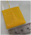 | 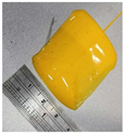 | 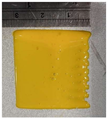 |
| Length | 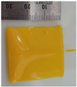 | 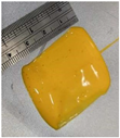 | 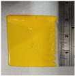 |
| Discharge Direction | Path Design | |||
|---|---|---|---|---|
| 1st Condition | 2nd Condition | 3rd Condition | 4th Condition | |
| Width |  |  | 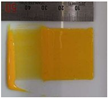 |  |
| Length | 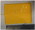 |  | 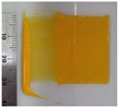 | 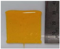 |
Disclaimer/Publisher’s Note: The statements, opinions and data contained in all publications are solely those of the individual author(s) and contributor(s) and not of MDPI and/or the editor(s). MDPI and/or the editor(s) disclaim responsibility for any injury to people or property resulting from any ideas, methods, instructions or products referred to in the content. |
© 2023 by the authors. Licensee MDPI, Basel, Switzerland. This article is an open access article distributed under the terms and conditions of the Creative Commons Attribution (CC BY) license (https://creativecommons.org/licenses/by/4.0/).
Share and Cite
Ji, C.; Cha, A.; Shin, D. Design of Viscosity and Nozzle Path Using Food 3D Printer and Pneumatic Pressure Syringe-Type Dispensing System. Appl. Sci. 2023, 13, 12234. https://doi.org/10.3390/app132212234
Ji C, Cha A, Shin D. Design of Viscosity and Nozzle Path Using Food 3D Printer and Pneumatic Pressure Syringe-Type Dispensing System. Applied Sciences. 2023; 13(22):12234. https://doi.org/10.3390/app132212234
Chicago/Turabian StyleJi, Changuk, Areum Cha, and Dongbin Shin. 2023. "Design of Viscosity and Nozzle Path Using Food 3D Printer and Pneumatic Pressure Syringe-Type Dispensing System" Applied Sciences 13, no. 22: 12234. https://doi.org/10.3390/app132212234
APA StyleJi, C., Cha, A., & Shin, D. (2023). Design of Viscosity and Nozzle Path Using Food 3D Printer and Pneumatic Pressure Syringe-Type Dispensing System. Applied Sciences, 13(22), 12234. https://doi.org/10.3390/app132212234