Abstract
Shield tunneling underneath existing rectangular pipe jacking can often lead to uneven settling. To solve the problem of excessive deformation of the existing underground pedestrian passages, excavated via the rectangular pipe-jacking method due to the adjacent shield tunnels construction beneath, a safety control plan has been proposed based on the shield tunnels constructed beneath a well-type underground pedestrian passage in Hohhot Subway. This plan involves the use of both numerical simulations and on-site monitoring to investigate the deformation patterns of the rectangular pipe jacking. The results suggest that the combined approach of interlayer soil grouting and steel support reinforcement is not only appropriate but also feasible for on-site implementation. It can be concluded that interlayer soil grouting for reinforcement was applied successfully to improve the strength of surrounding soils. Steel support reinforcement is advantageous for controlling the relative deformation between pipe segments. The maximum settlement induced by the shield tunneling for Passage A and Passage B was measured at 17.67 mm and 10.08 mm, respectively, with the final settlement distribution of the rectangular pipe jacking taking on a “W” shape. This study could provide a reference for the design and construction of shield tunnels that undercross existing rectangular pipe-jacking tunnels.
1. Introduction
As the construction of urban rail transit is developing rapidly, new challenges often arise when building subway tunnels that need to pass close by existing rectangular pipe jacking. Unlike shield tunnels, rectangular pipe-jacking segments are poured as single unit and are connected longitudinally using “F”-type socket joints, which do not incorporate bolts, making these joints a vulnerable aspect of the rectangular pipe-jacking structure. The construction of a new shield tunnel beneath existing structures inevitably disturbs the structure of the existing rectangular pipe-jacking tunnel. Rectangular pipe jacking is highly sensitive to uneven ground settlement, making it prone to pipe-segment bending and misalignment, thereby resulting in issues such as underground water seepage, as well as sand and mud leakage, all of which pose a significant threat to the safety and normal operation of the rectangular pipe-jacking tunnel structure.
At present, there is a relatively mature construction method for rectangular pipe-jacking construction [1,2,3]. Some scholars have also carried out some research on the response of rectangular pipe-jacking tunnels. Based on the analysis of tunnel parameters, Yu et al. [4] proposed a better method to predict the jacking force of pipe-jacking technology in long-distance driving. Zhang et al. [5] proposed a calculation method for determining vertical earth pressure and frictional resistance of rectangular pipe jacking by establishing a box soil–lubricant contact model. Ma et al. [6] proposed a new pipe–soil contact model to predict the friction force of pipe-jacking construction under lubrication conditions with higher accuracy, and verified it via numerical simulation and using field monitoring data. Through three-dimensional numerical simulation, Zhang et al. [7] studied the influence of different construction stages on roadways and subway tunnels during pipe-jacking construction. Ma et al. [8] analyzed the response of jacking rectangular pipes with different geometric parameters to the ground and their stress state in the construction of the pipe-jacking method. Cheng et al. [9] analyzed the variation law of the parameters of shallow-buried, large-section box-jacking tunnels through on-site monitoring data, and studied the supporting effect of conditional soil in the process of box jacking by establishing a fine three-dimensional numerical model. Ma et al. [10] analyzed the influence of parallel rectangular pipe-jacking construction on land subsidence under different pipe thickness and spacing parameters based on numerical simulation. Xu et al. [11] introduced a safer pipe-jacking construction method that reduces the soil-carrying effect of the overlying soil by filling with additional soil above the surface.
Up until now, many scholars have conducted research on similar projects involving the construction of new shield tunnels beneath existing structures. That research is mainly divided into four types: theoretical calculation [12,13,14,15,16,17,18,19], numerical modeling [20,21,22,23,24,25,26,27,28], model testing [29,30,31], and field monitoring [32,33,34,35]. Zhang et al. [36] proposed an analytical solution in order to analyze the response of an existing tunnel to a new tunnel excavation underneath. Gan et al. [37] established an improved semi-analytical method, considering the horizontal motion of a tunnel by using a Timoshenko beam lying on a Pasternak foundation, to study the influence of the asymmetric ground motion at any oblique angle caused by the new tunnel on the longitudinal response of the existing tunnel. Based on a two-stage method, Ding et al. [38] calculated the deformation of an existing tunnel caused by the large-diameter slurry shield using the theoretical formula while considering multiple construction factors. Using numerical simulation, Zhou et al. [39] studied the mechanical response of an existing tunnel and the stability of the underground excavation area when a subway station crossed an existing tunnel at a distance of zero. Xu et al. [40] studied the influence of new tunnels with different excavation sequences and grouting reinforcement ranges on existing pipelines above. Using the finite element model, Nasser et al. [41] analyzed the ground deformation caused by a new tunnel undercrossing an existing tunnel, and obtained some parameters to control the deformation. Xue and Zhang [42] studied the support pressure of the excavation face when a new tunnel crossed beneath an existing tunnel, and analyzed its influence on the surface settlement and segment deformation. Based on the model test method, Lin et al. [43] studied the deformation characteristics and the variation law of soil pressure of an existing horseshoe tunnel and rectangular tunnel when a shield tunnel passed underneath. Through field monitoring, Fang et al. [44] studied the settlement characteristics of an existing tunnel and the surface when twin tunnels were constructed beneath existing shield-driven twin tunnels. Through field monitoring, Jin et al. [45] studied the settlement and stress of an existing tunnel when a twin tunnel was excavated beneath the existing tunnel twice. In summary, the research on new tunnels undercrossing existing structures mainly focuses on existing tunnels, existing foundation pits and existing buildings, and the research on new tunnels under existing rectangular pipe jacking needs to be supplemented. The safety of rectangular pipe-jacking tunnels cannot yet be accurately evaluated, resulting in a lack of data while taking corresponding control measures, seriously restricting the scale of construction of subway tunnels adjacent to existing tunnels excavated using the rectangular pipe-jacking method in urban areas. This important problem urgently needs to be solved.
Based on the shield tunneling of Line 2 of Hohhot’s urban rail transit system beneath existing rectangular pipe jacking, a set of protective measures has been devised. These measures encompass interlayer soil grouting and internal steel support reinforcement. This study involved the use of numerical simulations to analyze the settling behavior of the existing rectangular pipe jacking under various reinforcement scenarios, thus furnishing theoretical guidance for on-site construction. Subsequently, the effectiveness of the engineering implementation was assessed through on-site monitoring, with a comprehensive comparison between simulated and actual measurements serving as validation. The study revealed the deformation characteristics of the underground pedestrian passage excavated by the rectangular pipe-jacking method. This could improve the design theory of rectangular pipe-jacking tunnels and lay the foundation for controlling the safety of the existing rectangular pipe-jacking tunnels during the construction of new tunnels.
2. Project Overview
2.1. Project Introduction
The Zhongshan Road Station-to-Xinhua Square Station section of Urban Rail Transit Line 2 in Hohhot was constructed using shield tunneling. The shield tunnel has an approximate burial depth of 12.1 m, an outer diameter of 6.2 m, a shield segment thickness of 0.35 m, and a tunnel spacing of 9.8 m. The shield tunnel crosses beneath the Xilinnan Road and Zhongshan Road intersection at a 65-degree angle, interacting with the underground pedestrian passages project. The distance from the shield tunnel’s arch to the bottom plate of the underground pedestrian passages is approximately 2.5 m. The layout of the underground pedestrian passages is in the form of “intersecting parallels”, with a width of 6.9 m, a height of 4.2 m, and a burial depth of 5.4 m, forming a single-story box-like structure underground. The interchange hall is constructed using the cut-and-cover method, while the passage utilizes the rectangular pipe-jacking method. Each pipe segment has a length of 1.5 m. In total, there are 32 pipe segments in Passage A, spanning a length of 48 m, and 28 pipe segments in Passage B, covering a total length of 42 m. The spacing between Passage A and B is 50 m. The engineering plan is depicted in Figure 1.
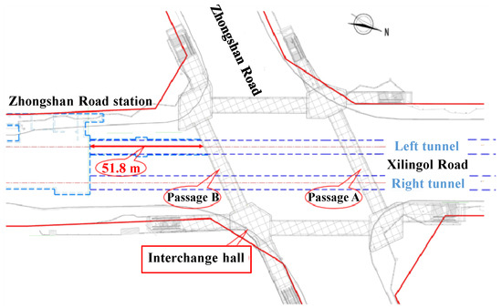
Figure 1.
Engineering plan.
2.2. Geological Conditions of the Project
The section from Zhongshan Road Station to Xinhua Square Station is situated on a gently sloping plain formed by the deposition of alluvial fan sediments. The terrain is characterized by its flat and expansive nature, with a subtle southwestward inclination. Ground elevations in this region range from approximately 1053.5 to 1054.96 m, resulting in a relative height difference of approximately 1 m. The area where tunneling is planned beneath the underground passage primarily consists of gravel and silt. The geological profile is depicted in Figure 2.
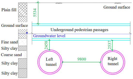
Figure 2.
Geological profile diagram (unit: mm).
2.3. Strategy of Construction Support
2.3.1. Interlayer Soil Grouting
Interlayer soil grouting reinforcement was performed to improve the strength of the surrounding soils. Several high-strength, flexible grouting pipes were employed to perform high-pressure grouting into the interlayer soils between the shield tunnel and existing tunnels. This process created a reinforced curtain, further enhancing the strength of the interlayer soil. After the shield tunneling machine cleared the existing tunnel, the soil within the outer channel area was subjected to additional grouting reinforcement through grouting holes in the tunnel segments. This helped to increase the segment’s strength and stability, reducing the subsequent settling of the existing tunnel structure. Each tunnel segment was equipped with three grouting holes, and the grout mixture consisted of cement and sodium silicate mixed in an equal volume ratio. The grout formed a curtain with a thickness of no less than 2 m. Grouting pressure was maintained at 0.3 to 0.6 MPa, and both grouting pressure and volume were closely monitored and controlled. Grouting commenced once the tunnel machine had advanced by five rings. After grouting was complete, the grouting head was removed, and the holes were sealed. In this process, ordinary Portland cement with a grade of P.C32.5 was used, the grouting pipes had a DN32 diameter, a 2.75 mm wall thickness (t), and a length (L) of 3 m. DN32 signifies a grouting pipe with an outer diameter of 32 mm, t represents the wall thickness of the grouting pipe (2.75 mm), and L indicates the length of the grouting pipe (3 m). The grouting reinforcement process is depicted in Figure 3.
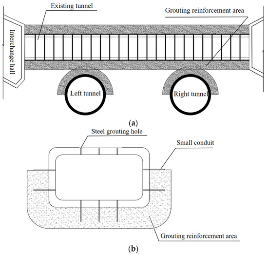
Figure 3.
Grouting reinforcement diagram. (a) Interlayer soil grouting; (b) segment grouting.
2.3.2. Steel Support Reinforcement
To reinforce the tunnel, an interior steel support framework was installed within the existing tunnel structure. This reinforcement spanned the entire length of Passages A and B, through which the shield tunnel passed. The steel support framework utilized welded 25b channel steel, with diagonal bracing made from 10# channel steel. Support sets were placed at 3 m intervals, creating a robust steel framework structure. A 2-m pedestrian passage was maintained in the center to ensure the overall stability of the existing tunnel structure. The installation of the steel support framework is illustrated in Figure 4.
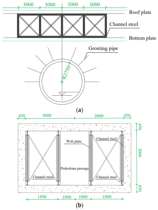
Figure 4.
Steel support layout (unit: mm). (a) Longitudinal section; (b) cross-section.
3. Feasibility of Construction Plan
3.1. Establishment of Numerical Model
3.1.1. Model Establishment
A three-dimensional numerical model was constructed using the 3D finite element software Midas GTS NX (2020). The nonlinearity of materials and the initial stress state of soils could be considered in the software, which could further reflect the actual site condition. Under the different loads and boundary conditions, static, dynamic, consolidation and construction phase analysis can be carried out. Midas GTS NX works using a multi-frontal solver. The solver has the advantage of reducing the number of calculations and memory requirements. In addition, computational efficiency may be improved. It can provide more dependable results for complex engineering analysis and design. The model’s dimensions are as follows: along the x-axis, it spans 79 m; along the y-axis, it covers 101 m; and along the z-axis, it extends 30 m. The spatial layout of the tunneling section, which includes the shield tunnel and the underground pedestrian passages (comprising 4 pedestrian passages and 4 interchange halls), faithfully replicates the actual project layout, as illustrated in Figure 5. The model consists of 199,429 mesh elements and 106,404 nodes. In the simulation, the outer diameter of the shield tunnel lining is 6.2 m, with a width of 1.5 m and a thickness of 0.45 m. The thickness of the underground pedestrian passages is also 0.45 m.
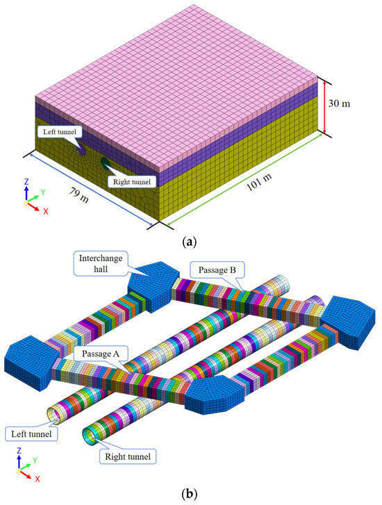
Figure 5.
Three-dimensional numerical model. (a) Model overview; (b) spatial relationships.
3.1.2. Calculation Parameters
The geological environment at the site is notably intricate. Based on the geological survey report for the shield tunneling area, the strata are simplified into three categories: plain fill soil, gravel, and silty clay, which are regarded as nonlinear materials. The Mohr–Coulomb model is uniformly applied for the strata and grouting soils. The parameters for the grouting reinforcement areas are determined based on relevant data and literature. The pertinent parameters for strata are outlined in Table 1. It is worth noting that the cohesion of gravel is set to 0 according to the geological survey report of this project and previous studies [33,46,47]. Both the shield tunnel and rectangular pipe-jacking tunnel structures are regarded as elastic materials and modeled with linear elastic model. They have a unit density of 24 kN/m3, an elastic modulus of 31 GPa, and a Poisson’s ratio of 0.2. The shield tunnel is typically made of C50 concrete with a thickness of 0.35 m. The shield shell and tunnel segments can be simulated using plate elements. Steel supports are modeled using beam elements. Detailed calculation parameters for the structure are provided in Table 2.

Table 1.
Calculation parameters of strata.
Table 2.
Calculation parameters of structure.
3.2. Design of Numerical Simulation
To avoid the occurrence of joint failure and groundwater seepage, lots of the measures can be adopted during the actual project to reduce the deformation of existing rectangular pipe-jacking tunnels. Based on some previous cases, interlayer soil grouting and steel support reinforcement are the most effective methods. A total of four schemes for numerical simulation were devised. Scheme 1 entails no reinforcement measures and is abbreviated as “No Reinforcement”. Scheme 2 involves interlayer soil grouting reinforcement, as illustrated in Figure 6a. Scheme 3 utilizes steel support reinforcement, depicted in Figure 6b. Scheme 4 combines both grouting and steel support reinforcement and is referred to as “Comprehensive Reinforcement”. The parameters of the shield machine should be adjusted appropriately. The chamber pressure and grouting pressure of the shield machine are the most important factors, as the parameters usually change during shield tunneling. In this paper, the parameters of the shield machine are not considered.
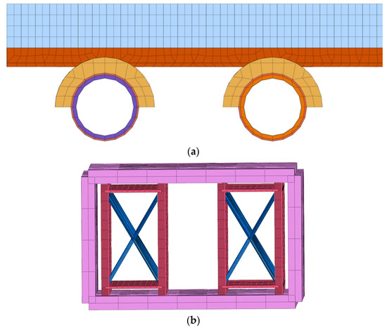
Figure 6.
Illustrations of different reinforcement approaches. (a) Grouting reinforcement; (b) steel support reinforcement.
3.3. Analysis of Numerical Results
Upon the completion of the shield tunnel construction, final settlement and deformation curves for the existing underground Passages A and B were plotted and are presented in Figure 7.
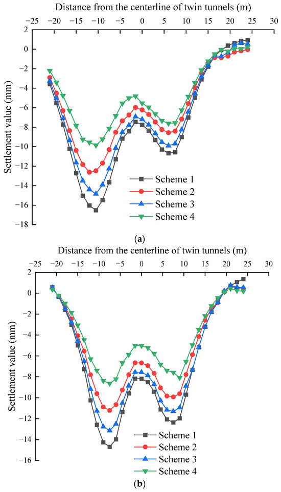
Figure 7.
Cross-sectional settlement of rectangular pipe jacking. (a) Passage A; (b) Passage B.
To facilitate a comprehensive comparison of settlement and deformation in both passages under different conditions, the maximum vertical displacements of the existing tunnels in different schemes are detailed in Table 3.
Table 3.
Maximum settlement value of rectangular pipe-jacking tunnels.
Different reinforcement schemes did not alter the deformation pattern of the settlement trough in the cross-section of the existing tunnel. In the end, they all led to an asymmetric “W”-shaped settlement trough. However, implementing reinforcement measures effectively reduced the values of maximum settlement caused by the shield tunnel crossing the existing tunnel, as detailed in Table 3. All three reinforcement schemes met engineering safety control standards. Yet, upon comparative analysis, it was evident that the comprehensive reinforcement scheme, which combined grouting and steel supports, delivered the most effective control over the vertical settlement and deformation of an existing tunnel. Under this scheme, the maximum settlement values induced by the new shield tunnel for Passages A and B were 9.95 mm and 8.64 mm, respectively. These values represented reductions of 39.8% and 42.1%, respectively, compared to the original condition with no reinforcement measures in place.
When analyzing the use of a single reinforcement method, under the sole application of grouting reinforcement, the values of maximum settlement induced for Passages A and B were 12.48 mm and 11.21 mm, respectively. Compared to the original condition with no reinforcement measures, these maximum settlement values decreased by 24.5% and 23.7%, respectively. Conversely, when relying solely on steel support reinforcement, the maximum settlement values induced for Passages A and B were 14.84 mm and 13.15 mm, respectively. Compared to the original condition with no reinforcement measures, these maximum settlement values decreased by 10.5% and 10.7%, respectively. In summary, when employing a single reinforcement method, the grouting reinforcement scheme proves to be more effective than the steel support reinforcement scheme. Steel support reinforcement strengthens the interior of the existing tunnel, resulting in better control over relative deformations between tunnel segments. However, the weight of the steel structure exerts additional pressure on the existing tunnel, which can have a somewhat unfavorable impact on controlling the overall displacement of the existing tunnel.
A comparison of the maximum vertical displacement from settlements in Passages A and B under different reinforcement schemes shows that the reinforcement effect is slightly better for Passage B. This is mainly attributed to Passage B’s smaller span relative to Passage A, resulting in greater overall stiffness of shorter beams compared to longer ones. Implementing reinforcement measures not only controls the settlement deformation of the existing tunnel, but also mitigates upward deformation in areas further away from the shield tunnel directly above. Similarly, the comprehensive reinforcement scheme involving grouting and steel supports demonstrates the most effective control over the upward deformation of the existing tunnel. Upon comparison, it is clear that the reinforcement effect of the comprehensive reinforcement is not simply the sum of the effects of the other two separate reinforcement schemes when it comes to controlling the settlement and deformation of the existing rectangular pipe-jacking tunnel. This indicates that the comprehensive reinforcement scheme, which combines grouting and steel support, fully capitalizes on the reinforcement effects of both methods within the strata, resulting in a “synergistic effect”. Following a comprehensive analysis of on-site construction economics and the safety control effectiveness of various reinforcement measures, it has been determined that only grouting reinforcement measures will be implemented during the actual construction of the shield tunnel on the site.
4. Analysis of On-Site Monitoring Results
4.1. On-Site Monitoring
4.1.1. Layout of Monitoring Points
Considering the specific conditions at the construction site of the existing tunnel, a monitoring plan was meticulously crafted to provide a real-time assessment of the safety status of the existing structures. Given that the existing tunnel was constructed with individual rectangular pipe segments, each measuring 1.5 m in length, and that the joints between these segments experience the most significant variations in stress within the entire system, monitoring points were strategically placed at intervals of 1.5 m along the bottom axis of the existing tunnel’s structure and monitored using a hydrostatic level system [44]. Each point of the existing underground pedestrian passages was monitored with hydrostatic level cells, and the readings were taken every day before and after the shield face passing. In total, 64 monitoring points were installed, with 34 points dedicated to Passage A of the rectangular pipe-jacking tunnel and 30 points to Passage B, as depicted in Figure 8.
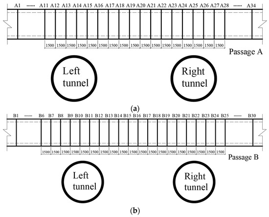
Figure 8.
Monitoring point layout (unit: mm). (a) Passage A; (b) Passage B.
4.1.2. Control Parameters
In line with the “Code for Monitoring Measurement of Urban Rail Transit Engineering” (GB 50911—2013) [48], the “Management Measures for Urban Rail Transit Construction Projects (Implementation) by Hohhot Urban Rail Transit Construction Management Co., Ltd.”, and the monitoring plan for this project, the cumulative settlement and deformation value for the rectangular pipe jacking was established at 20 mm.
4.2. Analysis of Monitoring Results and Comparison
4.2.1. Deformation of Rectangular Pipe Jacking
The distribution curve of settlement caused by the inclined twin-tunnel construction of the existing tunnel is shown in Figure 9. The initial passage of the new shield tunnel resulted in a maximum settlement of 14.94 mm for Passage A and 9.08 mm for Passage B of the existing tunnel. The maximum settlement occurred directly above the centerline of the new shield tunnel, forming a “V”-shaped curve in the settlement distribution. Approximately two and a half months after construction of the left tunnel was completed, the right tunnel was constructed in the reverse direction, leading to increased settlement and deformation of the existing tunnel. The maximum settlement of Passage A and Passage B of the existing tunnel caused by the second construction was 17.67 mm and 10.08 mm, respectively. The deformation of the existing tunnel structure also transitioned from the original “V”-shape to a “W”-shape, displaying an asymmetric distribution.
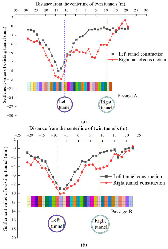
Figure 9.
Settlement distribution of the existing tunnel. (a) Passage A; (b) Passage B.
Analysis of measured data and settlement curves in conjunction with the real construction conditions indicates a deviation in the center of the settlement trough within the existing tunnel. This deviation is due to the inclined intersecting excavation of the new shield tunnel beneath the existing rectangular pipe-jacking tunnel. The shield cutter head reaches one side of the existing tunnel first, causing the soil in this area to be disturbed initially by the tunneling process, leading to a relatively higher cumulative settlement in this specific region.
4.2.2. Comparison between Numerical Simulation and On-Site Monitoring
The comparison between numerical simulation and on-site monitoring is depicted in Figure 10. It is clear that the maximum settlement values in the existing underground pedestrian passage occur within the range directly above the centerline of the new shield tunnel. After the completion of the left tunnel, the distribution of settlement of the existing tunnels exhibits a “V”-shaped curve.
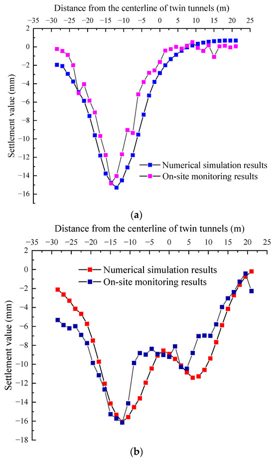
Figure 10.
Comparison between simulation and actual measurements. (a) Left tunnel construction; (b) right tunnel construction.
The maximum measured and simulated settlement in Figure 10a was 15.29 mm and 14.94 mm, respectively. The distribution exhibits a “V”-shaped curve, whereas after the completion of the right tunnel, the distribution exhibits a “W”-shaped curve. The maximum measured and simulated settlement in Figure 10b is 17.67 mm and 16.06 mm, respectively. In summary, the simulated results align reasonably well with the actual monitoring data, supporting the validity of the numerical simulation and preparing for subsequent safety control measures.
5. Conclusions
Based on a project of twin shield tunnels constructed beneath underground pedestrian passages in Hohhot Subway, both numerical simulations and on-site monitoring were performed to investigate the deformation patterns of the rectangular pipe jacking. The conclusions are as follows:
- (1)
- The combined approach of interlayer soil grouting and steel support reinforcement is not only appropriate but also feasible for on-site implementation. Interlayer soil grouting was applied to improve the strength of the surrounding soils. Steel support reinforcement is advantageous for controlling the relative deformation between segments.
- (2)
- The reinforcement effect is slightly better for Passage B, which is mainly attributed to Passage B’s smaller span relative to Passage A. The maximum settlement induced by the shield tunneling for Passage A and Passage B was measured at 17.67 mm and 10.08 mm, respectively. The simulation results align reasonably well with the actual monitoring data.
- (3)
- The maximum settlement of the existing tunnel occurred within the range directly above the centerline of the new tunnel. When a single track completes its construction, the settlement distribution exhibits a “V”-shaped curve, whereas twin-tunnel construction causes the settlement distribution to take on an asymmetric “W”-shaped curve.
Author Contributions
Conceptualization, J.H.; writing—original draft preparation, J.H.; writing—review and editing, J.H. and Z.Y.; investigation Z.Y.; data curation, Z.Y.; software, Z.Y.; visualization, Z.Y.; funding acquisition, X.Z.; resources, X.Z.; supervision, X.Z.; project administration, X.Z. All authors have read and agreed to the published version of the manuscript.
Funding
This research was funded by Analysis and Research on the Impact of Upper Pit Construction on the Deformation of Existing Tunnels and Control Technologies, grant number ZHDT-3T-KY004/2019, Young Talents of Science and Technology in Universities of Inner Mongolia Autonomous Region, grant number NJYT23103, and Fundamental Research Funds for Inner Mongolia University of Science & Technology was funded by 2023QNJS159.
Institutional Review Board Statement
Not applicable.
Informed Consent Statement
Not applicable.
Data Availability Statement
Data are contained within the article.
Acknowledgments
The authors are grateful to China Railway 20th Bureau Group 4th Engineering Co., Ltd., China for the assistance in providing information on the project.
Conflicts of Interest
Jun He was employed by the company Shenzhen Metro Group Co., Ltd. The remaining authors declare that the research was conducted in the absence of any commercial or financial relationships that could be construed as a potential conflict of interest.
References
- Zhang, P.; Ma, B.; Zeng, C.; Xie, H.; Li, X.; Wang, D. Key techniques for the largest curved pipe jacking roof to date: A case study of Gongbei tunnel. Tunn. Undergr. Space Technol. 2016, 59, 134–345. [Google Scholar] [CrossRef]
- Chen, X.; Ma, B.; Najafi, M.; Zhang, P. Long rectangular box jacking project: A case study. Undergr. Space 2021, 6, 101–125. [Google Scholar] [CrossRef]
- Wang, L.; Chen, X.; Su, D.; Liu, S.; Liu, X.; Jiang, S.; Gao, H.; Yang, W. Mechanical performance of a prefabricated subway station structure constructed by twin closely-spaced rectangular pipe-jacking boxes. Tunn. Undergr. Space Technol. 2023, 135, 105062. [Google Scholar] [CrossRef]
- Yu, B.; Shimada, H.; Sasaoka, T.; Hamanaka, A.; Matsumoto, F.; Morita, T. A jacking force study based on interpretation of box jacking records: A case study of curved rectangular box jacking in soft soil in Saitama, Japan. Tunn. Undergr. Space Technol. 2023, 139, 105228. [Google Scholar] [CrossRef]
- Zhang, Y.; Feng, X.; Zhou, H.; Zhang, P.; Ma, B.; Tan, L.; Wang, J. Pressure characteristics of rectangular box jacking considering box-soil-lubricant interaction. Tunn. Undergr. Space Technol. 2022, 126, 104569. [Google Scholar] [CrossRef]
- Ma, P.; Shimada, H.; Sasaoka, T.; Hamanaka, A.; Moses, D.; Dintwe, T.; Matsumoto, F.; Ma, B.; Huang, S. A new method for predicting the friction resistance in rectangular pipe-jacking. Tunn. Undergr. Space Technol. 2022, 123, 104338. [Google Scholar] [CrossRef]
- Zhang, D.; Liu, B.; Qin, Y. Construction of a large-section long pedestrian underpass using pipe jacking in muddy silty clay: A case study. Tunn. Undergr. Space Technol. 2016, 60, 151–164. [Google Scholar] [CrossRef]
- Ma, P.; Shimada, H.; Sasaoka, T.; Moses, D.; Matsumoto, F.; Chen, X. Investigation on the engineering effects of the geometrical configuration of the jacking rectangular pipe. Tunn. Undergr. Space Technol. 2022, 119, 104239. [Google Scholar] [CrossRef]
- Cheng, C.; Yang, H.; Jia, P.; Ni, P.; Shi, P.; Ma, P.; Xiang, Q. Face stability of shallowly buried large-section EPB box jacking crossing the Beijing-Hangzhou Grand Canal. Tunn. Undergr. Space Technol. 2023, 138, 105200. [Google Scholar] [CrossRef]
- Ma, S.; Li, M.; Jin, J.; Bai, K. The influence of shallow buried double-line parallel rectangular pipe jacking construction on ground settlement deformation. Alex. Eng. J. 2021, 60, 1911–1916. [Google Scholar] [CrossRef]
- Xu, X.; Tong, L.; Li, Z.; Liu, X.; Hu, Q.; Yao, H.; Li, J. Influence of extreme shallow jacked box tunnelling on underlying metro tunnels: A case study. Undergr. Space 2023, 12, 234–250. [Google Scholar] [CrossRef]
- Liu, B.; Yu, Z.; Zhang, R.; Han, Y.; Wang, Z.; Wang, S.J. Effects of undercrossing tunneling on existing shield tunnels. Int. J. Geomech. 2021, 21, 04021131. [Google Scholar] [CrossRef]
- Zhou, Z.; Chen, Y.; Liu, Z.; Miao, L. Theoretical prediction model for deformations caused by construction of new tunnels undercrossing existing tunnels based on the equivalent layered method. Comput. Geotech. 2020, 123, 103565. [Google Scholar] [CrossRef]
- Wang, G.; Fang, Q.; Du, J.; Wang, J.; Li, Q. Deep learning-based prediction of steady surface settlement due to shield tunnelling. Automat. Constr. 2023, 154, 105006. [Google Scholar] [CrossRef]
- Yu, J.; Li, H.; Huang, M.; Li, Y.; Tan, J.; Guo, Y. Timoshenko-beam-based response of existing tunnel to single tunneling underneath and numerical verification of opening and dislocation. Comput. Geotech. 2022, 147, 104757. [Google Scholar] [CrossRef]
- Fang, Q.; Wang, G.; Yu, F.; Du, J. Analytical algorithm for longitudinal deformation profile of a deep tunnel. J. Rock. Mech. Geotech. 2021, 13, 845–854. [Google Scholar] [CrossRef]
- Jin, D.; Yuan, D.; Ng, Y.; Pan, Y. Effect of an undercrossing tunnel excavation on an existing tunnel considering nonlinear soil-tunnel interaction. Tunn. Undergr. Space Technol. 2022, 130, 104571. [Google Scholar] [CrossRef]
- Zeng, L.; Zhang, D.; Lian, C.; Zhang, J.; Yin, H. Study on the influence of an under-crossing parallel double-line shield tunnel on the existing tunnel structure. Mathematics 2023, 11, 3125. [Google Scholar] [CrossRef]
- Xu, Q.; Zhu, Y.; Lei, S.; Fan, H.; Wang, D.; Ma, K.; Fang, Z. A Simplified 3D Theoretical Model for Calculating the Surface Settlement Induced by Tunnel Undercrossing Excavation. Int. J. Geomech. 2023, 23, 10. [Google Scholar] [CrossRef]
- Zhu, Q.; Ding, Y. Impact of new undercrossing tunnel excavation on the stability of the existing tunnel. Front. Earth. Sci. 2022, 10, 915882. [Google Scholar] [CrossRef]
- Lou, P.; Li, Y.; Lu, S.; Xiao, H.; Zhang, Z. Deformation and mechanical characteristics of existing foundation pit and tunnel itself caused by shield tunnel undercrossing. Symmetry 2022, 14, 263. [Google Scholar] [CrossRef]
- Fu, C.; Gao, Y. Numerical Analysis on the behavior of existing tunnels subjected to the undercrossed shield tunneling at a small proximity. Adv. Civ. Eng. 2021, 2020, 8823331. [Google Scholar] [CrossRef]
- Lai, H.; Zheng, H.; Chen, R.; Kang, Z.; Liu, Y. Settlement behaviors of existing tunnel caused by obliquely under-crossing shield tunneling in close proximity with small intersection angle. Tunn. Undergr. Space Technol. 2020, 97, 103258. [Google Scholar] [CrossRef]
- Peng, H.; Dong, Y.; Liu, L. Research on deformation influence of shield undercrossing the existing metro double shield tunnel. Adv. Mat. Res. 2014, 1065–1069, 378–382. [Google Scholar] [CrossRef]
- Lou, P.; Huang, W.; Huang, X. Analysis of shield tunnels undercrossing an existing building and tunnel reinforcement measures. Appl. Sci. 2023, 13, 5729. [Google Scholar] [CrossRef]
- Liu, B.; Xi, D.; Xu, P. Study on the interaction of metro shield tunnel construction under-crossing the existing Longhai railway. Geotech. Geol. Eng. 2020, 38, 2159–2168. [Google Scholar] [CrossRef]
- Zhang, C.; Han, K.; Zhang, D. Face stability analysis of shallow circular tunnels in cohesive-frictional soils. Tunn. Undergr. Space Technol. 2015, 50, 345–357. [Google Scholar] [CrossRef]
- Li, W.; Zhang, C.; Zhang, D.; Ye, Z.; Tan, Z. Face stability of shield tunnels considering a kinematically admissible velocity field of soil arching. J. Rock. Mech. Geotech. 2022, 14, 505–526. [Google Scholar] [CrossRef]
- Kim, S.; Burd, H.J.; Milligan, G. Model testing of closely spaced tunnels in clay. Geotechnique 1998, 48, 375–388. [Google Scholar] [CrossRef]
- Ng, C.W.W.; Hong, Y.; Soomro, M. Effects of piggyback twin tunnelling on a pile group: 3D centrifuge tests and numerical modelling. Geotechnique 2015, 65, 38–51. [Google Scholar] [CrossRef]
- Soomro, M.; Mangi, N.; Xiong, H.; Kumar, M.; Mangnejo, D. Centrifuge and numerical modelling of stress transfer mechanisms and settlement of pile group due to twin stacked tunnelling with different construction sequences. Comput. Geotech. 2020, 121, 103449. [Google Scholar] [CrossRef]
- Li, J.; Fang, Q.; Liu, X.; Du, J.; Wang, G.; Wang, J. Mechanical behaviors of existing large-diameter tunnel induced by horseshoe-shaped undercrossing twin tunnels in gravel. Appl. Sci. 2022, 12, 7344. [Google Scholar] [CrossRef]
- Zhang, X.; Cheng, H.; Xu, Y.; Li, H. A case study on performances of overlying pipelines due to shallow tunnels excavation in water-rich gravel ground. Ain. Shams. Eng. J. 2022, 13, 101746. [Google Scholar] [CrossRef]
- Wang, R.; Zhang, B.; Wang, Y. Analysis of settlement induced by shield construction of the metro passing under existing buildings based on the finite difference method. Geofluids 2022, 2022, 1206867. [Google Scholar] [CrossRef]
- Zhang, X.; Zhang, C.; Wang, J. Effect of closely spaced twin tunnel construction beneath an existing subway station: A case study. J. Test. Eval. 2018, 46, 1559–1573. [Google Scholar] [CrossRef]
- Zhang, D.; Huang, Z.; Li, Z.; Zong, X.; Zhang, D. Analytical solution for the response of an existing tunnel to a new tunnel excavation underneath. Comput. Geotech. 2019, 108, 197–211. [Google Scholar] [CrossRef]
- Gan, X.; Yu, J.; Gong, X.; Liu, N.; Zheng, D. Behaviours of existing shield tunnels due to tunnelling underneath considering asymmetric ground settlements. Undergr. Space 2022, 7, 882–897. [Google Scholar] [CrossRef]
- Ding, Z.; Zhang, M.; Zhang, X.; Wei, X. Theoretical analysis on the deformation of existing tunnel caused by under-crossing of large-diameter slurry shield considering construction factors. Tunn. Undergr. Space Technol. 2023, 133, 104913. [Google Scholar] [CrossRef]
- Zhou, Z.; Zhou, X.; Li, L.; Liu, X.; Wang, L.; Wang, Z. The construction methods and control mechanisms for subway station undercrossing an existing tunnel at zero distance. Appl. Sci. 2023, 13, 8829. [Google Scholar] [CrossRef]
- Xu, Q.; Zhang, W.; Chen, C.; Lu, J.; Tang, P. Study on settlement influence of newly excavated tunnel undercrossing large diameter pipeline. Adv. Civ. Eng. 2022, 2022, 5700377. [Google Scholar] [CrossRef]
- Nasser, A.; Mohamed, S.; Adel, A.; Kamal, M. Field monitoring and numerical analysis of ground deformation induced by tunnelling beneath an existing tunnel. Cogent. Eng. 2021, 8, 1. [Google Scholar] [CrossRef]
- Xue, F.; Zhang, M. Stability of excavation face on shield tunnel undercrossing existing tunnel. Geotech. Res. 2020, 7, 96–102. [Google Scholar] [CrossRef]
- Lin, Q.; Lu, D.; Lei, C.; Tian, Y.; Kong, F.; Du, X. Mechanical response of existing tunnels for shield under-crossing in cobble strata based on the model test. Tunn. Undergr. Space Technol. 2022, 125, 104505. [Google Scholar] [CrossRef]
- Fang, Q.; Zhang, D.; Li, Q.; Wong, L. Effects of twin tunnels construction beneath existing shield-driven twin tunnels. Tunn. Undergr. Space Technol. 2015, 45, 128–137. [Google Scholar] [CrossRef]
- Jin, D.; Yuan, D.; Li, X.; Zheng, H. An in-tunnel grouting protection method for excavating twin tunnels beneath an existing tunnel. Tunn. Undergr. Space Technol. 2018, 71, 27–35. [Google Scholar] [CrossRef]
- Wang, F.; Du, X.; Li, P.; Hou, S. A meso-scale numerical modelling method for the stability analysis of tunnels in sandy cobble stratum. Transp. Geotech. 2022, 38, 100921. [Google Scholar] [CrossRef]
- He, S.; Li, C.; Wang, D.; Liu, X. Surface settlement induced by slurry shield tunnelling in sandy cobble strata—A case study. Indian Geotech. J. 2021, 51, 1349–1363. [Google Scholar] [CrossRef]
- GB 50911-2013; Code for Monitoring Measurement of Urban Rail Transit Engineering. China Architecture & Building Press: Beijing, China, 2013. (In Chinese)
Disclaimer/Publisher’s Note: The statements, opinions and data contained in all publications are solely those of the individual author(s) and contributor(s) and not of MDPI and/or the editor(s). MDPI and/or the editor(s) disclaim responsibility for any injury to people or property resulting from any ideas, methods, instructions or products referred to in the content. |
© 2023 by the authors. Licensee MDPI, Basel, Switzerland. This article is an open access article distributed under the terms and conditions of the Creative Commons Attribution (CC BY) license (https://creativecommons.org/licenses/by/4.0/).