Abstract
In a three-coil wireless power transfer system with relay coils, the transmission efficiency and output power of the system decreases with changes in the adjacent coupling coefficients. Controlling the power of three-coil wireless power transfer systems is also a significant challenge. To solve these issues, a three-coil wireless power transfer system based on parity–time symmetry is proposed in this paper. First, a three-coil parity–time wireless power transfer system was modeled based on a circuit model. Then, the transmission and gain characteristics of the three-coil parity–time wireless power transfer system were analyzed. It was found that when the system is in a parity–time-exact region, it can maintain a constant transmission efficiency and output power, and its output power is independent of the coupling coefficient. In addition, based on the output characteristics of the three-coil parity–time wireless power transfer system, a power control method and a working range detection method were proposed to attain a constant power output. Finally, a three-coil parity–time wireless power transfer system was experimentally tested.
1. Introduction
With technological development, electricity has become an indispensable part of life. Unlike wired power transmission, in which electrical energy is transmitted through wires or cables, wireless power transfer (WPT) has been widely used in consumer electronics, smart homes, physical robots, and implantable medical devices because of its high flexibility, convenience, and safety, without requiring any physical connections [1,2,3,4].
One of the types of WPT, magnetic resonance wireless power transfer, was proposed by MIT’s Kurs team in 2007 [5], and a large number of researchers subsequently invested in it [6,7]. They used four coils coupled with a medium distance to wirelessly light a 60 W light bulb through the strong magnetic resonance theory in physics combined with coupled-mode modeling theory. However, the transmission efficiency and output power of the system decreased significantly with increasing distance.
To ensure the robustness of the transmission efficiency of a WPT system toward coil coupling distance, Assasaworrarit et al. introduced a wireless power transfer system using parity–time (PT) symmetry theory in 2017 and constructed a negative resistor, using an operational amplifier to replace the traditional excitation source. When the system operated in the PT-exact symmetry region, the transmission efficiency of the system did not vary with the coupling coefficient between the coils [8]. Although the power of this system was only on the order of milliwatts, the output characteristics of this system and its circuit characteristics, namely, the lack of a requirement for additional complex control loops, have attracted many researchers to the study of WPT systems using PT symmetry theory [9]. Zhou et al. used a self-oscillating inverter to achieve a negative-resistance composition and, thus, increase the output power of a system to a level that can be applied to electronic devices, and it could maintain a transmission efficiency of more than 90% within a distance of 100 mm from the coupling coil [10]. In Ref. [11], a PT-symmetric system was applied to multiple decoupled receiver coils to achieve high-power wireless energy transmission with low current stress in each receiver coil. In Ref. [12], a steady-state analysis of the PT-symmetric system was performed using the mutual inductance model of the circuit, and a primary-side output power control scheme was proposed according to the characteristics of the PT-symmetric interval. Unlike the coupled-mode theory modeling reported in [10], modeling based on circuit mutual inductance theory can more precisely describe the correlation between system transmission performance and circuit parameters.
Although the PT-symmetric system is robust regarding transmission efficiency over the transmission distance, it exists only in the PT-exact symmetry region [8]. When the coupling coefficient of the system is less than the critical value, the system will lose its robustness toward the coupling distance because it operates in the PT-broken region. However, this property is only satisfied in the PT-exact symmetry region. As the coil transmission distance increases, the system begins operating in the PT-broken region, and the constant transmission characteristic of the system is not satisfied. In Ref. [9], the critical coupling coefficient of the studied system was reduced by connecting an inductor in series to the resonant tank on the secondary side that did not participate in the coupling. In Ref. [13], a DC–DC link was added to the secondary side of the system, reducing the critical coupling coefficient of the system by changing the equivalent AC resistance of the system and, thus, its necessary coupling coefficient. However, additional components increase the size of the receiving end.
In addition to the methods above, a WPT system with multiple relay coils can effectively extend the transmission distance. In Refs. [14,15,16], a scheme was proposed to realize long-distance wireless power transfer with multiple loads based on a relay resonant tank constructed using a double-coupled coil. In PT-WPT, Zhou et al. analyzed the system output characteristics as well as the frequency characteristics based on the coupled-mode theory for different numbers of relay coils [17]. In Ref. [18], based on a single relay coil, a parallel–series capacitor compensation topology was used for the receiving coil, increasing the freedom of coupling coefficient adjustment. In Ref. [19], based on a three-coil WPT, variable inductance and variable capacitance elements were added to cope with the system detuning caused by the coupling coefficient change between coils. However, the theories of these articles are based on coupled-mode modeling, which analyzes a system’s resonant tank from an overall perspective and does not reflect the voltage and current gain characteristics of a system [10].
Knowledge of the output characteristics of a WPT system are essential in practice. Owing to the features of the PT-exact symmetry region, the authors of [20,21,22] realized the switching of the two charging modes of CC and CV for a dual-coil PT-WPT system using primary-side information only. There is yet to be an article reporting the analysis of the voltage and current gains and the control of the output of a three-coil parity–time wireless power transfer system. This is because modeling with the coupled-mode theory does not directly reflect the relationship between the electrical system parameters.
In this study, a novel power control method based on a three-coil PT-WPT system is proposed. The proposed system’s resonant tanks adopt capacitor series compensation. Unlike most output control systems, the proposed output control system only requires current and voltage information at the transmitting end and does not require communication at the receiving end. In addition, based on the frequency characteristics of the three-coil PT-WPT system, a working range detection method is proposed, which only requires information from the transmitting end. To save space for the model, the relay coil and receiver coil of the system were designed with multilayer coils, and the parameters of the coils were optimized. The research results of this article provide valuable insights for further research on the three-coil PT-WPT system.
The rest of this paper is organized as follows. Section 2 models the circuit model of the three-coil PT-WPT system using the circuit mutual inductance theory and analyzes the gain characteristics and transmission characteristics of the three-coil PT-WPT system. Section 3 proposes an output control strategy for DC loads based solely on the current and voltage information of the primary side to realize the DC load using only the current–voltage information on the primary side. Section 4 presents an analysis of the parameters of the system and the design of an experimental prototype. Finally, some conclusions are given in Section 5.
2. Modeling and Analysis of the Three-Coil PT-WPT System
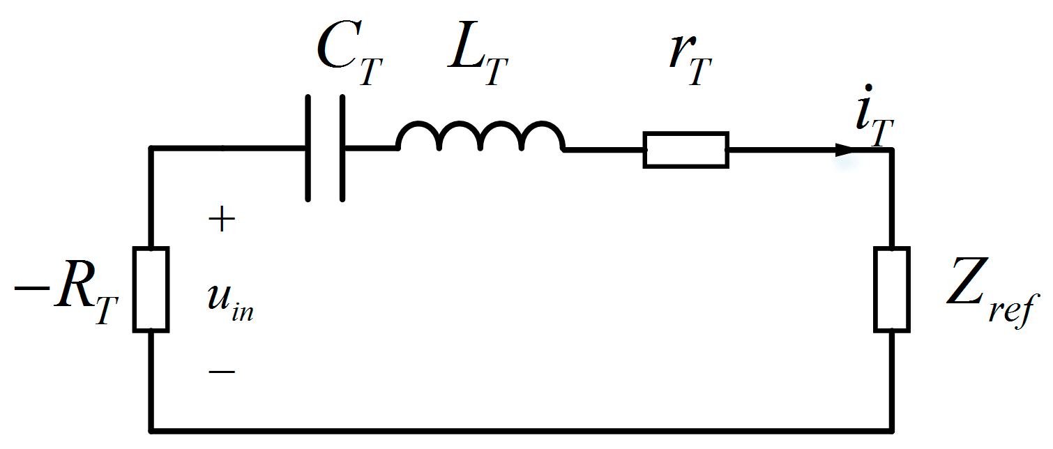
2.1. Circuit Model of the Three-Coil PT-WPT System
Figure 1 displays a schematic of the proposed three-coil PT-WPT system employing capacitor series compensation. Luo et al. [23] established a negative resistor using a full bridge inverter, achieving PT symmetry within the system. The proposed system exhibits controllable negative resistance owing to a DC–DC module based on a full bridge inverter, with , , , and representing the negative resistance, inductance, compensation capacitance, and internal coil resistance of the transmitting coil’s resonant tank, respectively. , , and represent the coil inductance, compensation capacitance, and internal coil resistance, respectively. , , , and represent the inductance, compensation capacitance, internal coil resistance, and load AC equivalent resistance of the load coil resonant tank, respectively. represents the coupling between the coils.
Figure 1.
Equivalent circuit of a three-coil PT-WPT system.
The circuit model for a three-coil PT-WPT with an operating angular frequency can be established by applying Kirchhoff’s voltage law and circuit theory, and is mathematically expressed as follows: (1) Assuming that the distance between the receiving coil and the transmitting coil is considerably large, the cross-coupling effect is negligible (). Additionally, the internal resistance of the relay coil can be neglected, considering its high-quality factor ().
Here, , , and represent the intrinsic resonant angular frequencies of the transmit resonant tank, relay resonant tank, and receive resonant tank, denoted as , , and , respectively; and are the coupling coefficients between the adjacent coils, expressed as and .
In the context of a two-coil PT-WPT system [10], the transmitting and receiving coils necessitate identical intrinsic resonant frequencies (i.e., ). Similarly, in a three-coil PT-WPT system with a relay coil, specific conditions must be fulfilled:
where is a custom parameter. To obtain a non-zero solution, the determinant of (1) must be zero, meaning that both the real and imaginary parts must be zero [22]. Therefore,
The real part of the imaginary part of (3) can be resolved into the two polynomials
and
, which cannot be satisfied simultaneously. Instead, three angular frequency solutions for the three-coil PT-WPT system:
where , and is the critical coupling coefficient in a three-coil PT-WPT system.
2.2. Transmission Characteristics
As depicted in (4), unlike the two-coil PT-WPT system, the three-coil PT-WPT system has three modes of operation. When , the system operates within the PT-exact symmetry region, featuring two frequency branches for the system’s operating frequency. The system’s operating frequency fluctuates continuously with the coupling coefficient . When the operating frequency satisfies , the system operates in the resonant state, akin to a standard three-coil MCR-WPT system. When , frequency bifurcation persists, leading to two branched frequencies with varying operating frequencies concerning the coupling coefficient.
The currents and represent the root mean square (RMS) of the current and , respectively. By substituting (2) into (1) and simplifying it, the relationship between current and can be obtained.
2.2.1. In the PT-Exact Symmetry State
In the PT-exact symmetry state, the system functions within a PT-exact symmetric realm, where the gain and output characteristics remain unaffected by the system’s coupling coefficient.
This assertion is justified by Equation (4). As observed, when the system resides in the PT-exact symmetric region, the operating frequency of the system satisfies . By substituting Equation (4) into Equation (5),
2.2.2. In the PT-Broken State
In the PT-broken state, the system operates in a region where the gain and output characteristics fluctuate with the coupling coefficient. Here, the operating frequency satisfies . Substituting into Equation (4) results in the following equations:
2.2.3. In the Resonant State
In this state, the voltage and current gains mirror those in (6), suggesting that the output power and transmission efficiency of the system are consistent with those in (7), respectively.
3. Proposed Three-Coil PT-WPT System
In this section, a three-coil PT-WPT system, characterized by its rated output traits, is introduced and thoroughly analyzed. The system’s structure is meticulously examined, and a control strategy utilizing a singular side parameter to secure a constant output power is devised.
3.1. With Boost Converter and Receiver Side Rectifier Model
The system configuration, involving the Boost converter and rectifier, is illustrated in Figure 2. The relationship between the inverter input voltage and the DC supply voltage can be expressed as follows:
where is the duty cycle. At the receiving end, the electrical energy is converted into DC power through a full-bridge rectifier with filter capacitors to act on the DC load . The voltage at both ends of the DC load was , and the rectifier input voltage and current were and , respectively. Accounting for the filter capacitors, only the fundamental wave of the current–voltage at the rectifier end is considered. The current flowing through the DC load is expressed as follows:
Figure 2.
Main circuit of the proposed WPT system with boost converter.
Assuming neglect of the rectifier’s power loss, the relationship between the DC load and the equivalent AC load is expressed as follows:
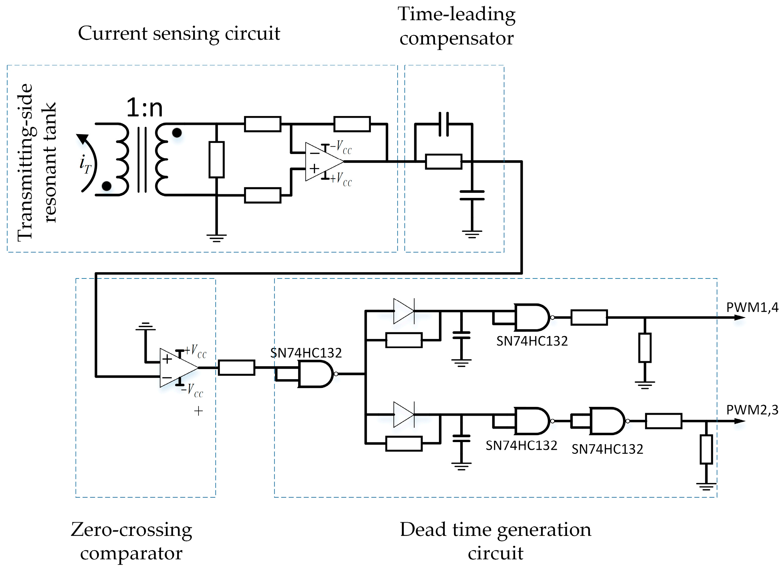
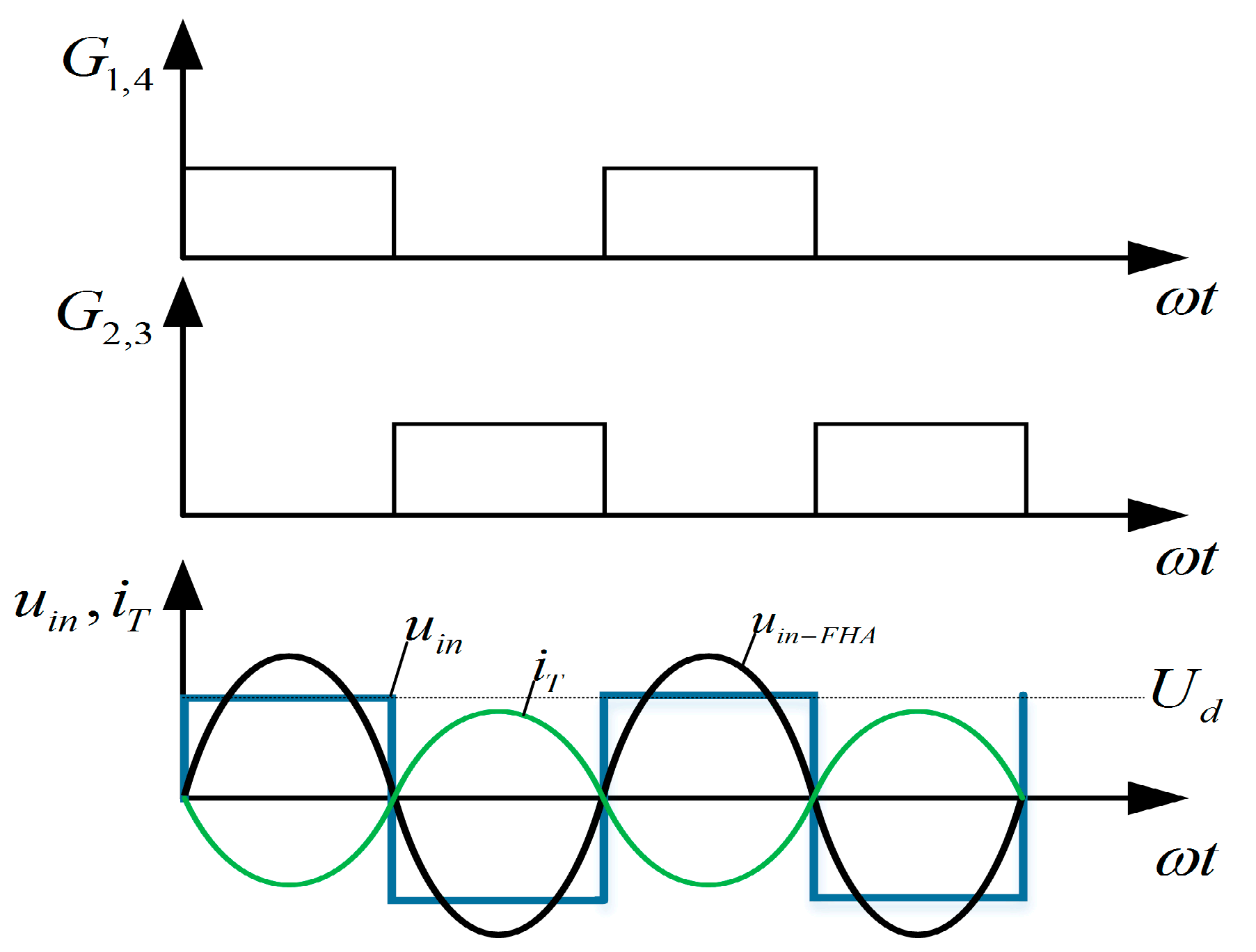
3.2. Self-Oscillation Control Strategy for Achieving Constant Output
In the context of the previous section’s analysis, the three-coil PT-WPT system, characterized by negative resistance, functions within the PT-exact state. In this state, the output voltage and current are exclusively linked to the system’s internal parameters. The equivalent AC output voltage, current, and power remain constant as the system stabilizes.
Negative resistance can be achieved by sampling the loop current within the resonant tank at the transmitting end. Figure 3 illustrates the negative-resistance control circuit and its implementation strategy. The current is sampled, captured, and transformed into a voltage signal by a current-sense transformer CU8965. It is then directed to the zero-crossing comparator AD8611 and dead time generation circuit to convert it into rectangular PWM signals. The isolated driver chip Silicon Labs SI8271, serves as the driver for the full-bridge inverter circuit, amplifying the PWM signals from the comparator.
Figure 3.
Inverter control circuit diagram implementing negative resistance.
Figure 4 shows the full-bridge inverter output waveform and the PWM signal governed by self-oscillation control. Ideally, disregarding the MOSFET switching dead time, the duty cycle width of the PWM signal of switches S1–S4 is 50%. The inverter output voltage and its fundamental component are in phase with the current . The effective values of the fundamental component of the inverter output voltage and the inverter input voltage are expressed as follows:
Figure 4.
Negative resistance control circuit and inverter output waveform.
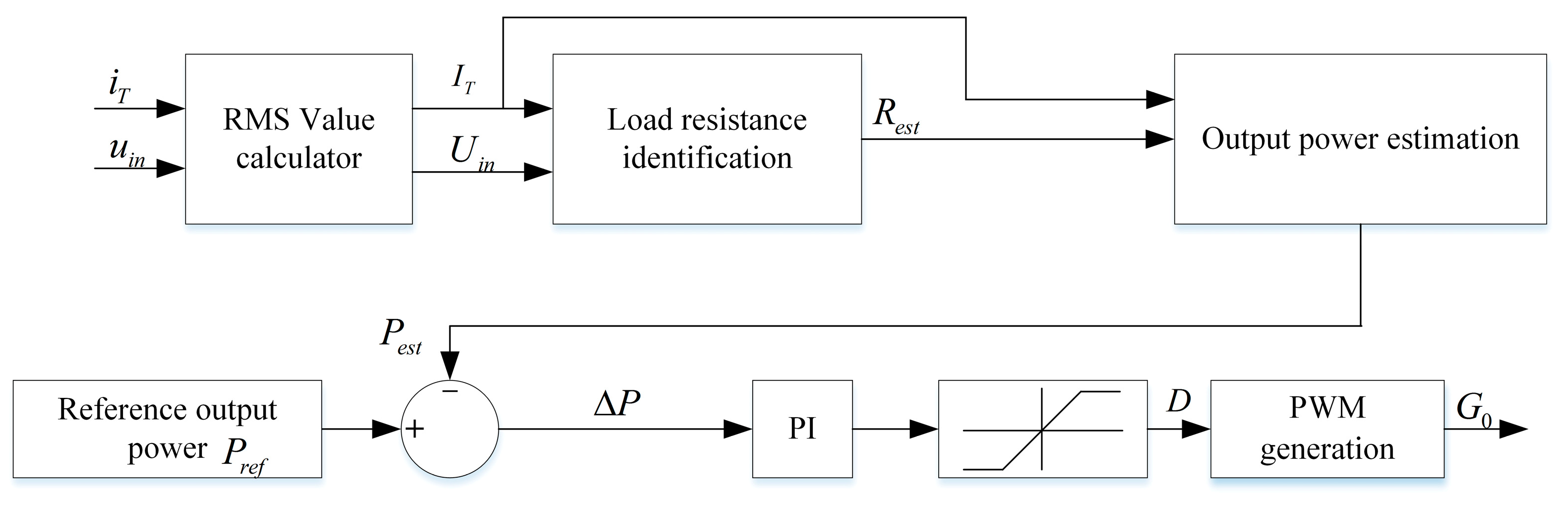
3.3. Online Load Resistance Identification and System Status Detection
For the three-coil PT-WPT system to operate in the exact state, ensuring identical coupling coefficients between adjacent coils is imperative. The equivalent load-resistance data and real-time information on the load and the distance between coupling coils must be acquired.
By combining (3) and (13) with , the estimated load resistance can be derived as follows:
In [3], a system operating mode analysis was performed by detecting the working frequency and comparing the relationship between the operating frequency and the intrinsic resonant frequency. However, in the operating broken state of the three-coil PT-WPT system, a bifurcation frequency exists, making it challenging to judge the operating mode through a frequency comparison. To discern whether the system is functioning within the PT-exact state, it is proposed to calculate the inverter output voltage and current RMS using reflected impedance analysis.
The equivalent transmitting-side circuit of the system is shown in Figure 5, and the input impedance of the system is expressed by (15):
Figure 5.
Equivalent circuit diagram with the reflected impedance on the transmitting side.
Upon substituting the expression for operating frequency from (4) to (15),
In the PT-exact and resonant states, the system exhibits a consistent input impedance. This input impedance consistently complies with (16) when the system functions in the resonant state. Therefore, the system’s input impedance can be computed as a reference value by transmitting a PWM signal with a fixed frequency before the system commences operation. This input impedance calculation was conducted during self-oscillation control, issuing a misalignment warning when the system was in the broken region. The flow of the system’s working state detection is illustrated in Figure 6.
Figure 6.
Flowchart of system working status detection.
3.4. Variable Negative Resistance Control Strategy Based on Primary Side Regulation
Building upon the analysis in Section 2.2, it is evident that the system’s output power solely relies on the system’s equivalent AC load and the inverter output voltage when functioning within the PT-exact symmetry region. Consequently, adjusting the duty cycle of the boost circuit alters the negative resistance and, consequently, the inverter output voltage .
By combining (10) and (13), the equivalent AC load output power of the system is obtained as follows:
Equation (17) depicts that output regulation can be attained by adjusting the boost converter’s duty cycle. Assuming the power loss of the full-bridge rectifier is negligible, the output power of the DC load satisfies . By combining (6) and (11), the estimated DC output power of the system can be calculated as follows:
Upon determining the estimated system’s output power, the system’s output power is regulated through the closed-loop PI control shown in Figure 7. As the load changes, the real-time assessment of output current and output voltage are obtained, and their RMS values of the fundamental wave are individually computed. The DC load resistance and output characteristics are estimated using (14) and (18), while the estimated output value is compared with a preset reference value representing the desired output characteristics. The error is fed to the PI controller, which generates the duty cycle . The switching driver then produces the PWM signal and propels the boost converter. This control method can be effectively implemented within the exact state of the system PT using a straightforward control algorithm and obviates the necessity for system resonant cavity topology switching.
Figure 7.
The control block diagram of the proposed closed-loop control method with rated output power.
4. Experimental Verification
Building on the earlier analysis, an experimental prototype was meticulously devised and produced to assess the performance of the proposed three-coil PT-WPT system, emphasizing a consistent output operation mode controlled from the transmitting side.
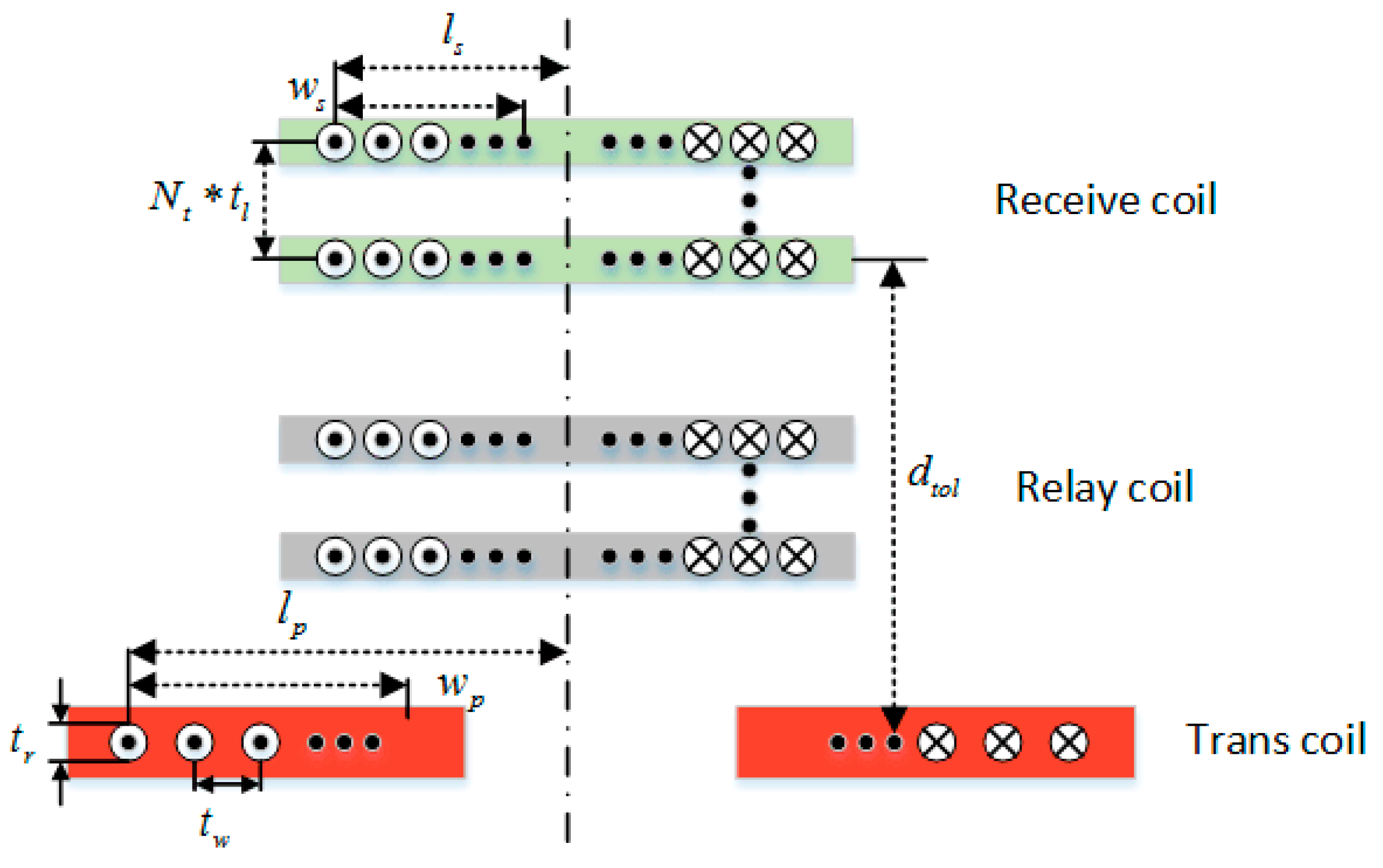
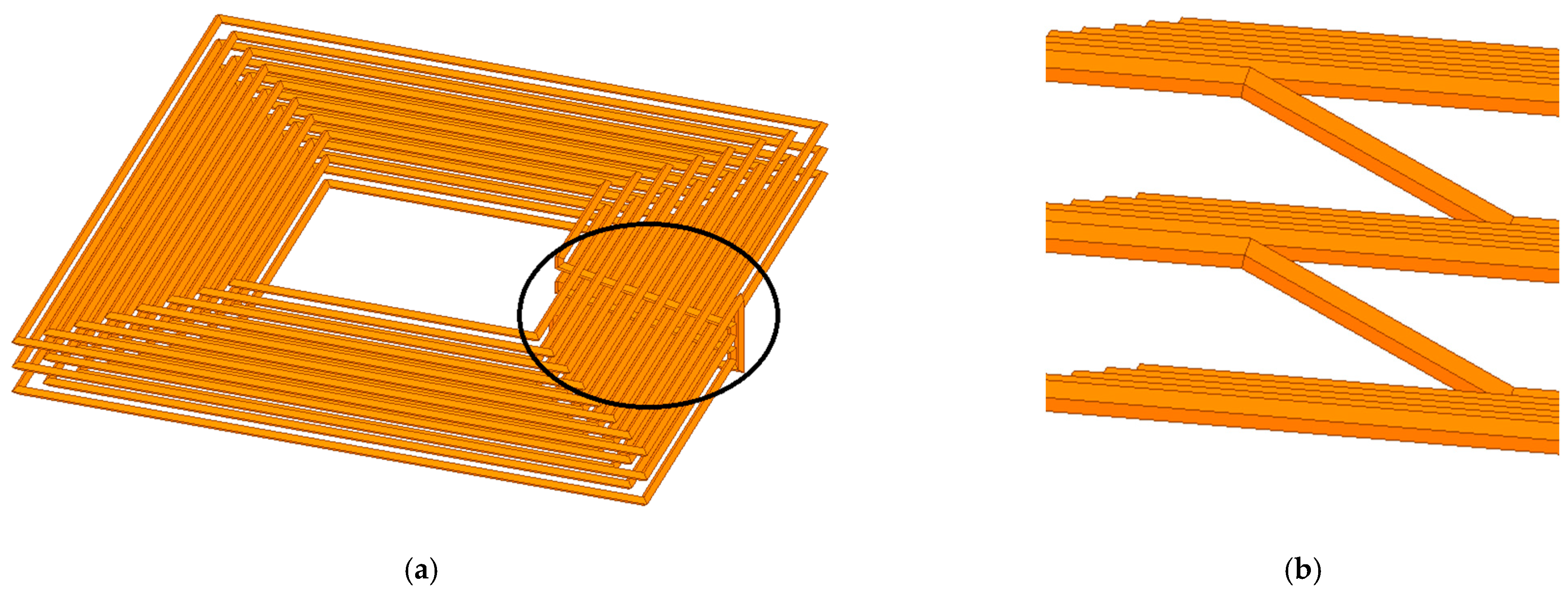
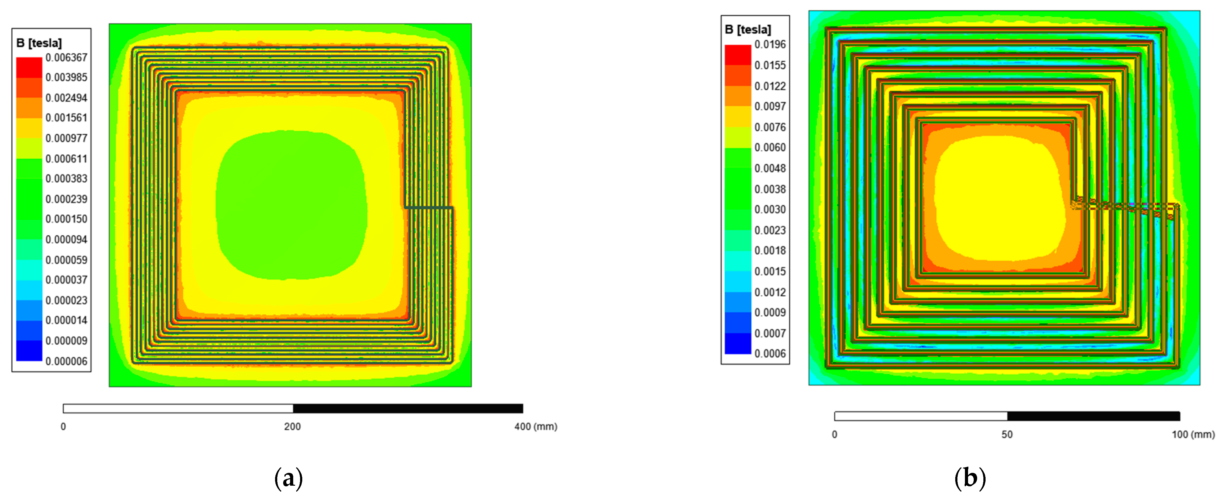
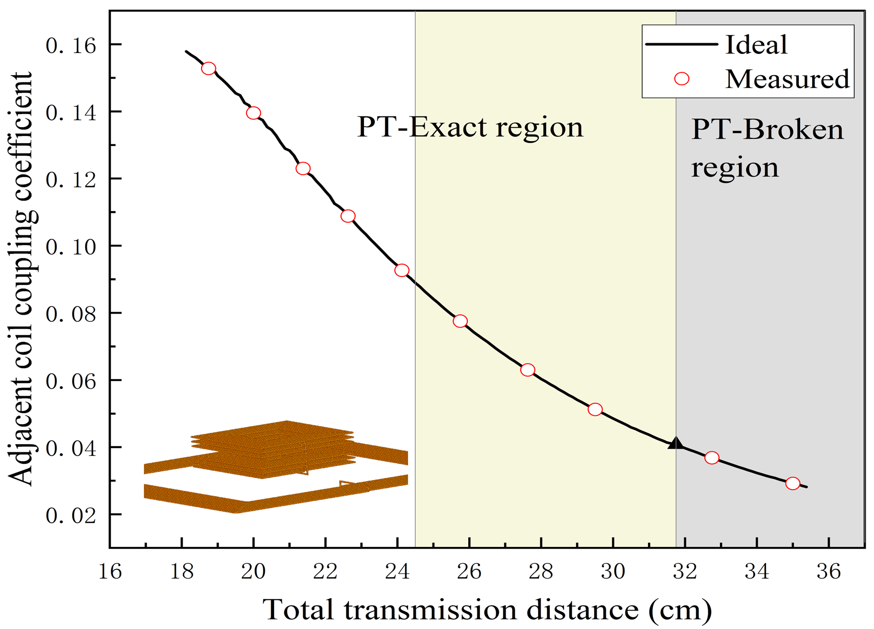
4.1. Coupling Coil Structure Design and Simulation
For the three-coil PT-WPT system, the coupling coil must meet specific criteria. Firstly, the transmitting coil should have a substantial transmission area to facilitate a large flux region. Additionally, the relay and receiving coils need to conserve space. This study employed square coils with rounded corners to reduce sharp current changes at right angles for both the relay and receiving coils, maintaining a high quality factor. To conserve space, a multilayer coil winding method was utilized to augment the coil’s self-inductance. The system’s structure is schematically depicted in Figure 8. The self-inductance of a multilayer coil is composed of the self-inductance of each layer, the strong positive mutual inductance between the coils, and the staggered connection between the coil layers, as depicted in Figure 9a,b. The self-inductance and mutual inductance between two adjacent resonant cavities can be expressed by Equations (19) and (20).
where denotes the self-inductance of layer of the multilayer coil and denotes the mutual inductance of layer and layer coils.
where denotes the mutual inductance between the transmitting coil and the coil of layer of the relay coil, and denotes the mutual inductance between layer of the relay coil and layer of the receiving coil.
Figure 8.
Multilayer coil structure schematic.
Figure 9.
(a) Multilayer coil simulation diagram. (b) Connection of each layer.
The relationship between the coil’s internal resistance, its radius, number of layers, turns per layer, and turn spacing in the multilayer coil were examined. This analysis also considered the impact of increased self- and mutual inductance on the coupling coefficient and flux loss resulting from a significant variance in the number of coil turns. The relay and receiver coils shared the same design constraints, leading to the transmitting coil and multilayer coil’s similar design requirements.
and represent the numbers of turns of the transmitting and multilayer coils, respectively. and denote the distances from the center of the transmitting coil and multilayer coils to the outermost layer of the coil, respectively.
To satisfy the three-coil PT symmetry condition, it is crucial to disregard the multilayer coil’s internal resistance and mutual inductance , considering the coil’s boundary constraint.
The optimized coil parameters are shown in Table 1.
Table 1.
Design parameters of transmitting and multilayer coils.
The magnetic field intensity distributions of the single-layer transmitting coil and the multilayer coil were studied using ANSYS 2022 R1 Maxwell finite element analysis software. Figure 10 illustrates the magnetic field intensity distributions of both coils under the same excitation.
Figure 10.
Coil magnetic field distribution diagram. (a) Single-layer transmitting coil. (b) Multilayer coil.
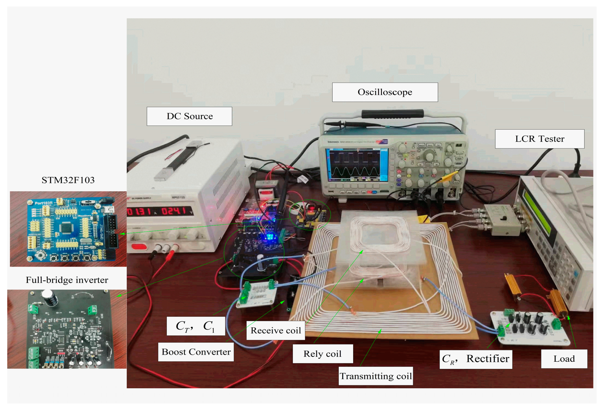
4.2. Experimental Construction
An experimental prototype was developed to validate the proposed theoretical analysis and parametric design method. The coils were wound with Leeds wire ( strands, outside ) to counteract the skin effect, adhering to the specifications in Table 1. The experimental set up, as depicted in Figure 11, included three designed coupling coils, a 50 V DC input voltage provided by the KXN-10010D DC power supply, and boost converter (MOSFET: Infineon IRFP4227PBF, Schottky diode: ON MBR40250TG). The resonant tank compensation capacitor was derived by connecting several chip capacitors in parallel, and the RMS value was sampled using AD637. The full-bridge rectifier circuit at the receiver side consisted of four Schottky diodes (V15PM15) using an electronic load as the test load. Table 2 lists the other measured parameters of the system.
Figure 11.
Experimental prototype of the proposed WPT system based on three-coil PT-symmetry.
Table 2.
The experimental parameters.
The relocation of the relay and receiving coils was performed with a radial shift to ensure uniform coupling coefficients among adjacent coils. Figure 12 illustrates the fluctuation in coupling coefficients of adjacent coils at different total transmission distances. The theoretical findings were derived from Neumann’s equation [24], while the actual mutual inductance was determined using a precision impedance analyzer (Wayne Kerr 6500 B) coupled with an LCR tester (Agilent 4263 B). The graph indicates the PT-exact symmetry area of the dual-coil PT-WPT system in white and the PT-exact symmetry regions of the three-coil PT-WPT system in white and yellow. The grey area indicates the PT-broken symmetry region within the three-coil PT-WPT system.
Figure 12.
Measurement results of the coupling coefficient between adjacent coils and the total transmission distance.
4.3. Experimental Results
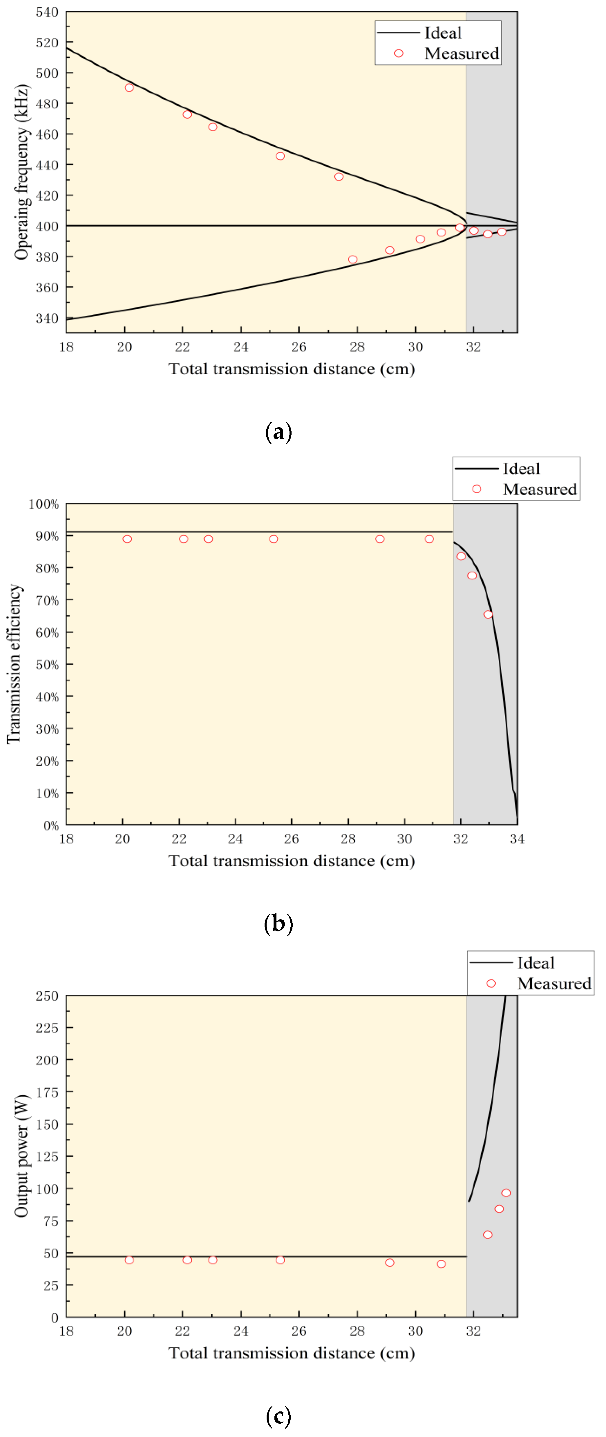
4.3.1. Steady-State Performance of the System
Figure 13 displays the experimental frequency, output power, and transmission efficiency curves for different total transmission distances, when . As depicted in Figure 13a, the measured switching frequency aligns with the calculated results in Figure 13c, maintaining the system’s transmission efficiency at around 89% and a steady output power of approximately 48 W. Once the total transmission distance exceeds 32 cm, the system operates in the PT-broken region, substantially reducing the transmission efficiency. Hence, it is essential to avoid operating in the PT-broken region. The experimental waveforms are depicted in Figure 14.
Figure 13.
Transmission performance curves concerning transmission distance: (a) operating frequency; (b) efficiency; (c) output power.
Figure 14.
Experimental waveforms of the proposed system.
The inverter’s output voltage and current, as shown in Figure 14, persistently maintain the same phase, affirming the method’s ability to retain a permanent negative resistance.
4.3.2. Experimental Results of the Proposed Control Strategy
To validate the proposed load prediction and rated-output power control strategy, the boost duty cycle was initially set at 0.5. Online load identification involved calculating the RMS values and at various loads using (14).
Table 3 summarizes the experimental results for and the corresponding error at . The error is less than 4.3% for adjacent coil coupling coefficients and , which decreases with increasing . The average value of can be used to reduce errors. The maximum error is 4.10% for , and the minimum error is 1.75%, corresponding to .
Table 3.
Experimental results of online load identification.
Figure 15 shows the experimental waveform plots for different output parameter settings. Table 4 illustrates the experimental results of the rated output control at a rated output power of 48 W. The table indicates that the error of the output power control strategy is less than 4% for various adjacent coil coupling coefficients and loads. The system’s output remained stable even with fluctuations in adjacent-coil coupling coefficients, confirming the accuracy of the constant-output control strategy.
Figure 15.
Experimental waveforms of the proposed system under different conditions. (a) ; (b) .
Table 4.
Error analysis of output power control.
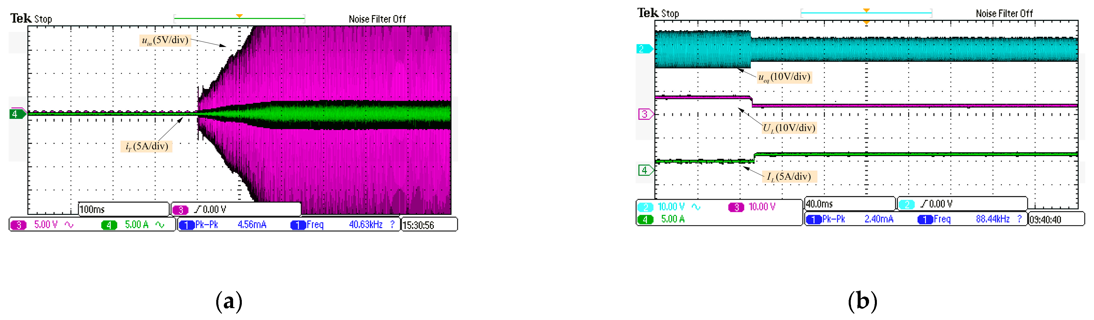
4.3.3. Dynamic Performance of the Proposed Three-Coil PT-WPT System
Figure 16 presents the dynamic waveform of the proposed system. Figure 16a illustrates the system’s start-up waveform for a coupling coefficient of 0.1 for adjacent coils. When the total transmission distance was fixed at 15 cm, a step change in the load resistor was executed, depicted in Figure 16b. With a sudden change in the DC load from 12 to 16 Ω in constant power mode, the waveforms show a reduction in load voltage from 7.35 to and an increase in load current from 2 to .
Figure 16.
Dynamic waveform of the proposed system at startup. (a) Startup status waveform. (b) Changing from 12 to 16 .
4.3.4. Error Analysis
The specific error between the experimental and theoretical data is attributed to various factors: (1) The asymmetric coupling coil design in this study resulted in deviations in coupling coefficients, yet the system retained PT symmetry. (2) The proposed multilayer coil internal resistance can only be controlled to a minimum in practice. (3) Tolerance in the coupling coil and compensation capacitor can shift the resonant frequency, while multiple parallel capacitors can resolve this and cause capacitor errors. (4) Experimental measurement equipment can also contribute to errors.
4.3.5. Comparison with Other WPT Systems
Compared with the two-coil PT-WPT system, the three-coil PT-WPT system significantly extends the distance between the special symmetry zones of the PT without adding complex controls or additional components. Table 5 contrasts the results in this paper with those in other published papers. The proposed system offers several advantages compared with other WPT systems: it achieves a consistent output independent of the coupling coefficient and load resistance.
Table 5.
Comparison between the proposed system and others.
5. Conclusions
This study examines the three-coil PT-WPT system by employing circuit theory. The system’s transmission efficiency, output power, and transmission gain were derived and compared with those of a two-coil PT-WPT system, demonstrating a notable enhancement in the PT-exact symmetry region. Furthermore, a novel control strategy for maintaining the system’s rated output power utilizing solely transmitter information is proposed based on the transmission characteristics of the three-coil PT-WPT system. This strategy enables the system to retain stability at predefined values, even when the load undergoes alterations. Additionally, a reflection impedance detection method is introduced to discern the system’s operation within the PT-exact region. The prototype design specifically employs a multilayer coil method for winding relay and receiver coils, and effectively reduces the spatial footprint of the system. The experimental results validate that the proposed control strategy can sustain a transmission efficiency exceeding 90%, aligned with the defined reference performance, while maintaining output performance errors below 5%. In summary, this method offers a substantial enhancement to PT-symmetric systems without complicating control mechanisms, thus indicating a wide range of potential applications.
Author Contributions
Conceptualization, J.Y. and Y.Y.; methodology, J.Y.; software, R.L.; validation, J.Y., Y.Y. and R.L.; formal analysis, J.Y.; investigation, J.Y.; resources, Y.Y.; data curation, R.L.; writing—original draft preparation, J.Y.; writing—review and editing, J.Y.; visualization, J.Y.; supervision, Y.Y.; project administration, Y.Y.; funding acquisition, Y.Y. All authors have read and agreed to the published version of the manuscript.
Funding
This research was funded by the Beijing Municipal Natural Science Foundation (No. 4204093) and the Fundamental Research Funds for Beijing University of Civil Engineering and Architecture (No. X20038, X20087).
Institutional Review Board Statement
Not applicable.
Informed Consent Statement
Not applicable.
Data Availability Statement
No new data were created or analyzed in this study. Data sharing is not applicable to this article.
Conflicts of Interest
The authors declare no conflict of interest. The funders had no role in the design of the study; in the collection, analyses, or interpretation of data; in the writing of the manuscript; or in the decision to publish the results.
References
- Fu, Y.; Shi, Z.; Zhu, Y.; Lv, K.; Peng, Z. PT Symmetry-Based AUV Dual Transmission Coil Wireless Power Transfer System Design. Machines 2023, 11, 146. [Google Scholar] [CrossRef]
- Rong, C.; Zhang, B.; Wei, Z.; Wu, L.; Shu, X. A Wireless Power Transfer System for Spinal Cord Stimulation Based on Generalized Parity–Time Symmetry Condition. IEEE Trans. Ind. Appl. 2022, 58, 1330–1339. [Google Scholar] [CrossRef]
- Wu, L.; Zhang, B.; Jiang, Y.; Zhou, J. A Robust Parity-Time-Symmetric WPT System With Extended Constant-Power Range for Cordless Kitchen Appliances. IEEE Trans. Ind. Appl. 2022, 58, 1179–1189. [Google Scholar] [CrossRef]
- Zhang, Z.; Zhang, B. Omnidirectional and Efficient Wireless Power Transfer System for Logistic Robots. IEEE Access 2020, 8, 13683–13693. [Google Scholar] [CrossRef]
- Kurs, A.; Karalis, A.; Moffatt, R.; Joannopoulos, J.D.; Fisher, P.; Soljacic, M. Wireless power transfer via strongly coupled magnetic resonances. Science 2007, 317, 83–86. [Google Scholar] [CrossRef]
- Zhaksylyk, Y.; Hanke, U.; Azadmehr, M. Single-Sided Interspiraled Inductive Impedance Matching for Magnetic Resonance Wireless Power Transfer. IEEE Trans. Circuits Syst. I Regul. Pap. 2023, 70, 2189–2200. [Google Scholar] [CrossRef]
- Chen, Z.; Sun, X.; Ren, B.; Wang, Z.; Liu, J. Analysis of four-coil magnetic resonance coupling wireless power transfer system based on LCC-SSS compensation network. Energy Rep. 2023, 9, 419–427. [Google Scholar] [CrossRef]
- Assawaworrarit, S.; Yu, X.; Fan, S. Robust wireless power transfer using a nonlinear parity-time-symmetric circuit. Nature 2017, 546, 387–390. [Google Scholar] [CrossRef]
- Wei, Z.; Zhang, B. Transmission Range Extension of PT-Symmetry-Based Wireless Power Transfer System. IEEE Trans. Power Electron. 2021, 36, 11135–11147. [Google Scholar] [CrossRef]
- Zhou, J.; Zhang, B.; Xiao, W.; Qiu, D.; Chen, Y. Nonlinear Parity-Time-Symmetric Model for Constant Efficiency Wireless Power Transfer: Application to a Drone-in-Flight Wireless Charging Platform. IEEE Trans. Ind. Electron. 2019, 66, 4097–4107. [Google Scholar] [CrossRef]
- Wu, L.; Zhang, B.; Zhou, J. Efficiency Improvement of the Parity-Time-Symmetric Wireless Power Transfer System for Electric Vehicle Charging. IEEE Trans. Power Electron. 2020, 35, 12497–12508. [Google Scholar] [CrossRef]
- Zhu, H.; Zhang, B.; Wu, L. Output Power Stabilization for Wireless Power Transfer System Employing Primary-Side-Only Control. IEEE Access 2020, 8, 63735–63747. [Google Scholar] [CrossRef]
- Chen, J.; Xie, F.; Zhang, B.; Chen, Y.; Xiao, W. Transmission range extension strategy of parity-time-symmetry-based wireless power transfer system by a boost converter. Int. J. Circuit Theory Appl. 2022, 51, 510–524. [Google Scholar] [CrossRef]
- Cheng, C.; Zhou, Z.; Li, W.; Zhu, C.; Deng, Z.; Mi, C.C. A Multi-Load Wireless Power Transfer System With Series-Parallel-Series Compensation. IEEE Trans. Power Electron. 2019, 34, 7126–7130. [Google Scholar] [CrossRef]
- Cheng, C.; Lu, F.; Zhou, Z.; Li, W.; Zhu, C.; Zhang, H.; Deng, Z.; Chen, X.; Mi, C.C. Load-Independent Wireless Power Transfer System for Multiple Loads Over a Long Distance. IEEE Trans. Power Electron. 2019, 34, 9279–9288. [Google Scholar] [CrossRef]
- Cheng, C.; Li, W.; Zhou, Z.; Deng, Z.; Mi, C. A Load-Independent Wireless Power Transfer System With Multiple Constant Voltage Outputs. IEEE Trans. Power Electron. 2020, 35, 3328–3331. [Google Scholar] [CrossRef]
- Shu, X.; Zhang, B.; Wei, Z.; Rong, C.; Sun, S. Extended-Distance Wireless Power Transfer System With Constant Output Power and Transfer Efficiency Based on Parity-Time-Symmetric Principle. IEEE Trans. Power Electron. 2021, 36, 8861–8871. [Google Scholar] [CrossRef]
- Wang, Z.; Qiu, D.; Zhang, B.; Xiao, W.; Chen, Y.; Xie, F. Extended-Range Wireless Power Transfer System Based on High-Order PT Symmetric Principle. In Proceedings of the 2021 IEEE 1st International Power Electronics and Application Symposium (PEAS), Shanghai, China, 12–15 November 2021; pp. 1–6. [Google Scholar]
- Qu, Y.; Zhang, B.; Gu, W.; Shu, X. Wireless Power Transfer System with High-Order Compensation Network Based on Parity-Time-Symmetric Principle and Relay Coil. IEEE Trans. Power Electron. 2023, 38, 1314–1323. [Google Scholar] [CrossRef]
- Wei, Z.; Zhang, B.; Shu, X.; Rong, C. A wireless power transfer system with hybrid control for constant current and voltage output. IEEE J. Emerg. Sel. Top. Power Electron. 2022, 10, 6317–6331. [Google Scholar] [CrossRef]
- Wu, L.; Zhang, B.; Jiang, Y. Position-Independent Constant Current or Constant Voltage Wireless Electric Vehicles Charging System Without Dual-Side Communication and DC–DC Converter. IEEE Trans. Ind. Electron. 2022, 69, 7930–7939. [Google Scholar] [CrossRef]
- Wu, L.; Zhang, B.; Jiang, Y. Robust Parity-Time-Symmetric WPT System with Reduced Switching-Frequency and Improved Step-Down Conversion Ratio. IEEE Trans. Transp. Electrif. 2022, 9, 2090–2103. [Google Scholar] [CrossRef]
- Luo, C.; Qiu, D.; Gu, W.; Zhang, B.; Chen, Y.; Xiao, W. Multiload Wireless Power Transfer System With Constant Output Power and Efficiency. IEEE Trans. Ind. Appl. 2022, 58, 1101–1114. [Google Scholar] [CrossRef]
- Liu, F.; Yang, Y.; Jiang, D.; Ruan, X.; Chen, X. Modeling and optimization of magnetically coupled resonant wireless power transfer system with varying spatial scales. IEEE Trans. Power Electron. 2016, 32, 3240–3250. [Google Scholar] [CrossRef]
- Hu, X.; Wang, Y.; Jiang, Y.; Lei, W.; Dong, X. Maximum efficiency tracking for dynamic wireless power transfer system using LCC compensation topology. In Proceedings of the 2018 IEEE Energy Conversion Congress and Exposition (ECCE), Portland, OR, USA, 23–27 September 2018; pp. 1992–1996. [Google Scholar]
- Tan, L.; Guo, J.; Huang, X.; Liu, H.; Wang, W.; Yan, C.; Zhang, M. Coordinated source control for output power stabilization and efficiency optimization in WPT systems. IEEE Trans. Power Electron. 2017, 33, 3613–3621. [Google Scholar] [CrossRef]
Disclaimer/Publisher’s Note: The statements, opinions and data contained in all publications are solely those of the individual author(s) and contributor(s) and not of MDPI and/or the editor(s). MDPI and/or the editor(s) disclaim responsibility for any injury to people or property resulting from any ideas, methods, instructions or products referred to in the content. |
© 2023 by the authors. Licensee MDPI, Basel, Switzerland. This article is an open access article distributed under the terms and conditions of the Creative Commons Attribution (CC BY) license (https://creativecommons.org/licenses/by/4.0/).